6474 - aemc
TRANSCRIPT

E N G L I S H User Manual
GROUNDFLEX® ADAPTER 6474

Statement of Compliance
Chauvin Arnoux®, Inc. d.b.a. AEMC® Instruments certifies that this instrument has been calibrated using standards and instruments traceable to international standards.
We guarantee that at the time of shipping your instrument has met its published specifications.
NIST traceable calibration is only possible when the Model 6474 is connected to the Ground Tester Model 6472.To obtain NIST calibration (for a nominal charge), the instrument would need to be returned to our facility, along with your Ground Tester Model 6472.
The recommended calibration interval is 12 months and begins on the date of receipt by the customer. For recalibration, please use our calibration services. Refer to our repair and calibration section at www.aemc.com.
Serial #: ________________________________
Catalog #: 2136.03
Model #: 6474
Please fill in the appropriate date as indicated:
Date Received: _________________________________
Date Calibration Due: _______________________
Chauvin Arnoux®, Inc.d.b.a AEMC® Instrumentswww.aemc.com

2 GroundFlex® Adapter Model 6474
Table of Contents
INTRODUCTION ..................................................................................... 31.1 International Electrical Symbols ...........................................................41.2 DefinitionofMeasurementCategories .................................................41.3 ReceivingYourShipment .....................................................................41.4 OrderingInformation ............................................................................5
1.4.1 AccessoriesandReplacementParts ......................................5
GROUNDFLEX® ADAPTER ...................................................................... 62.1 ControlFeatures ..................................................................................62.2 GroundFlex® Sensor ............................................................................7
2.2.1 CalibrationofGroundFlex® Sensors .......................................82.3 MeasurementsinAUTOMode ...........................................................10
2.3.1 PreparationoftheGroundFlex®Adapter ...............................102.3.2 MakingaMeasurement(ResistanceofLegs) ......................122.3.3 OtherMeasurements ............................................................14
2.4 MANUALModeandSWEEPMode ...................................................142.5 TowerTestingMeasurement ..............................................................16
2.5.1 ChoosingthepositionsfortheH,Selectrodes: ....................16
SPECIFICATIONS ................................................................................. 243.1 Electrical .............................................................................................243.2 Mechanical .........................................................................................263.3 Environmental ....................................................................................263.4 Safety .................................................................................................26
MAINTENANCE ................................................................................... 274.1 Maintenance.....................................................................................274.2 Cleaning ...........................................................................................27RepairandCalibration.................................................................................28TechnicalandSalesAssistance ..................................................................28LimitedWarranty .........................................................................................29WarrantyRepairs ........................................................................................29

GroundFlex® Adapter Model 6474 3
CHAPTER 1
INTRODUCTION
WARNING Thesesafetywarningsareprovidedtoensurethesafetyofpersonnel.Please read and complywiththeseprecautions:
• Thisinstrumentisprotectedfromaccidentalvoltagesofnotmorethan50VwithrespecttoearthinmeasurementCATIV.Theguaranteedlevelofprotectionofthisequipmentmaybecompromisedifusedinamannernotspecifiedbythemanufacturer.
• Safetyistheresponsibilityoftheoperator.
• Allmetalobjectsorwiresconnectedtotheelectricalsystemshouldbeassumedtobelethaluntiltested.Groundingsystemsarenoexception.
• Never exceed the maximum rated voltage and current, and themeasurementcategory.
• Never exceed the protection limits, and always comply with theconditionsandplaceofuse,indicatedinthespecifications.
• Donotusetheinstrumentoritsaccessoriesiftheyappeardamaged.
• Useaccessories thathaveovervoltagecategoryandservicevoltagesgreaterthanorequaltothoseoftheinstrument(CATIV50V).Useonlyaccessoriesthatcomplywithsafetystandards(IEC61010-2-031&32).
• Weartheappropriateprotectivegear(insulatingbootsandgloves).
• CheckthatnoterminalisconnectedandtheswitchissettoOFFbeforeopeningthedevice.
• Useonlythechargingunitsuppliedwiththeinstrumenttorechargethebattery.
• Troubleshootingandmetrologicalverificationproceduresmustonlybeperformedbyqualified,approvedpersonnel,orthefactory.
• NOTE: Thepotentialsonthevariousrodsusedforanearthmeasurementmaybedifferentifanearbyelectricalinstallationisdefectiveorcertainweather conditions prevail (thunderstorms). It is up to the operatorto decide whether to continue or postpone measurements in thesesituations.
4 GroundFlex® Adapter Model 6474
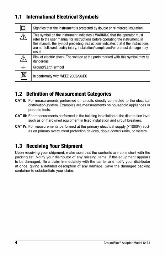
1.1 International Electrical Symbols
Signifies that the instrument is protected by double or reinforced insulation.
This symbol on the instrument indicates a WARNING that the operator must refer to the user manual for instructions before operating the instrument. In this manual, the symbol preceding instructions indicates that if the instructions are not followed, bodily injury, installation/sample and/or product damage may result.Risk of electric shock. The voltage at the parts marked with this symbol may be dangerous.
Ground/Earth symbol
In conformity with WEEE 2002/96/EC
1.2 Definition of Measurement CategoriesCAT II: Formeasurementsperformedoncircuitsdirectlyconnectedtotheelectrical
distributionsystem.Examplesaremeasurementsonhouseholdappliancesorportabletools.
CAT III: Formeasurementsperformedinthebuildinginstallationatthedistributionlevelsuchasonhardwiredequipmentinfixedinstallationandcircuitbreakers.
CAT IV: Formeasurementsperformedattheprimaryelectricalsupply(<1000V)suchasonprimaryovercurrentprotectiondevices,ripplecontrolunits,ormeters.
1.3 Receiving Your ShipmentUponreceivingyourshipment,makesurethatthecontentsareconsistentwiththepackinglist.Notifyyourdistributorofanymissingitems.Iftheequipmentappearstobedamaged,fileaclaimimmediatelywiththecarrierandnotifyyourdistributoratonce,givingadetaileddescriptionofanydamage.Savethedamagedpackingcontainertosubstantiateyourclaim.

GroundFlex® Adapter Model 6474 5
1.4 Ordering Information
NOTE: The GroundFlex® Adapter Model 6474 only operates in combination with the Ground Tester Model 6472 Kit - 500ft.
GroundFlex® Field Kit (Model 6472 and 6474) .............................Cat. #2136.03Includes: (Ground Tester Model 6472 Kit-500 ft (Cat #2135.54)); Model 6472, two carrying bags, two 500 ft. color-coded leads on spools (red/blue), two 100 ft. color-coded leads (hand tied, green/black), one 30 ft. lead (green), two 5 ft. color-coded leads (red/blue), 100/240V power adapter with US power cord, optical USB cable, four T-shaped auxiliary ground electrodes, set of five spaded lugs, one 100 ft. tape measure, rechargeable NiMH battery pack, USB stick with DataView software, ground tester workbook and user manual. GroundFlex® Adapter Model 6474, four GroundFlex® sensors (5m), twelve color-coded rings, connection lead, two extension leads on H reel (black/green) with color-coded alligator clips, one extra green and black alligator clips, two BNC extension leads, calibration loop, three C-clamps, set of 2-reel caddy’s, one inverter 12VDC to 120VAC watt (vehicle use), carrying case with wheels and handle for meters and user manual.
1.4.1 Accessories and Replacement Parts
Bag#6-CarryingBagforGroundKits ............................................. Cat. #2119.82TapeMeasure-AEMC®(100ft) .......................................................Cat. #2130.60Setoftwo,14.5"T-shapedAuxiliaryGroundElectrodes ..................Cat. #2135.39OpticalUSBCable............................................................................Cat. #2135.41Replacement-ConnectionLeadforModel6472/6474 ....................Cat. #2135.75Replacement-OneBNC(15m/50ft)ExtensionLead ......................Cat. #2135.76Replacement-Setof12,GroundFlex®Rings(red,yellow,brown,orange) .............................................................Cat. #2135.77Replacement-GreenExtensionLead .............................................Cat. #2135.78Replacement-BlackExtensionLead...............................................Cat. #2135.79Replacement-Setof3,C-clamps....................................................Cat. #2135.80Replacement-CalibrationLoop .......................................................Cat. #2135.82Replacement-CarryingCase ..........................................................Cat. #2135.83Replacement-OneGroundFlex®(5m/16ft)Sensor .........................Cat. #2135.92Replacement-SafetyAlligatorClip(black) ......................................Cat. #5000.99Replacement-SafetyAlligatorClip(green) .....................................Cat. #5100.06GroundFlex®Sensor10M .................................................................Cat. #2135.87
Order Accessories and Replacement Parts Directly OnlineCheck our Storefront at www.aemc.com/store for availability

6 GroundFlex® Adapter Model 6474
CHAPTER 2
GROUNDFLEX® ADAPTER
2.1 Control Features
50V CAT IV
1-2-3-4
1-2-3
1-2
1
2
3
4
For Use with theGround Tester Model 6472
GroundFlex®
Sensor SENSOR TURNS
SENSITIVITY
To Model 6472
Overload
INPUT
1
2
3
4
GroundFlex® AdapterMODEL 6474
2
4
1
6
5
3
1. Inputs1through4forGroundFlex® sensors
2. ConnectorforconnectionleadtotheGroundTesterModel6472
3. OVERLOAD indicator
4. SENSORTURNSselector:1,2,3or4
5. SENSITIVITYselector:x10,x1orx1/10
6. INPUTSELECTION:1,2,3,4,1-2,1-3or1-4
GroundFlex® Adapter Model 6474 7
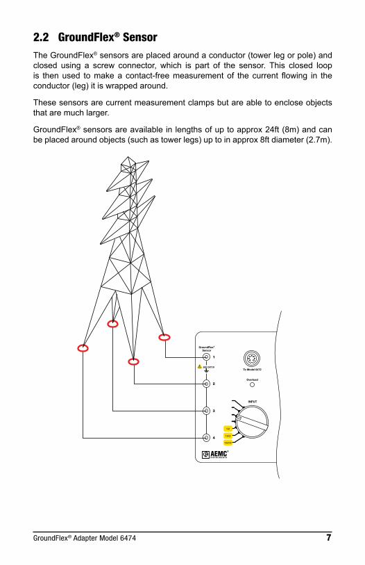
2.2 GroundFlex® SensorTheGroundFlex®sensorsareplacedaroundaconductor(towerlegorpole)andclosed using a screw connector, which is part of the sensor. This closed loopis thenused tomakeacontact-freemeasurementof thecurrent flowing in theconductor(leg)itiswrappedaround.
Thesesensorsarecurrentmeasurementclampsbutareabletoencloseobjectsthataremuchlarger.
GroundFlex®sensorsareavailableinlengthsofuptoapprox24ft(8m)andcanbeplacedaroundobjects(suchastowerlegs)uptoinapprox8ftdiameter(2.7m).
50V CAT IV
1-2-3-4
1-2-3
1-2
GroundFlex®
Sensor
To Model 6472
Overload
INPUT
1
2
3
4

8 GroundFlex® Adapter Model 6474
2.2.1 Calibration of GroundFlex® Sensors
Calibrationisnecessaryforanewsensor,onethatisnolongeridentifiedwhenasensorhasbeenreplaced,ormorethan2lengthsofextensioncableisused.ThecalibrationcoefficientsarethenstoredintheModel6474.
NOTE: Do not move or touch the GroundFlex® sensor or the calibration loop during the calibration. This could cause errors.
StartbyidentifyingeachsensorusingtheidentificationringsthataresuppliedwiththeModel6474:(1)Brown (2)Red (3)Orange (4)Yellow
• ConnectthecalibrationloopbetweenterminalsHandEoftheModel6472.
• ConnecttheModel6472and6474togetherusingtheconnectioncable.
• ConnecttheGroundFlex®sensorwiththeBrownringtoInput1oftheModel6474,theonewiththeRedringtoInput2,theonewiththeOrangeringtoInput3,andtheonewiththeYellowringtoInput4.
• CoiltheGroundFlex®sensorfourtimesaroundinthecalibrationloopandcloseitusingitsscrewconnector.Placetheconnectorasfaraspossiblefromthecalibration device.
6472 6474

GroundFlex® Adapter Model 6474 9
1. Settheswitchofthe6472toSET-UP.2. SettheSENSOR TURNSswitchto4.3. SettheSENSITIVITYswitchtox1.4. SettheINPUT SELECTIONswitchto1.
1-2-3-4
1-2-3
1-2
1
2
3
4
SENSOR TURNS
SENSITIVITY INPUT
5. PresstheHz/OPTIONSbutton5times.
ThedevicestartsbycomparingthecurrentIIntinjectedbythedeviceintothecalibrationlooptothecurrentIAmeasuredbytheGroundFlex®sensor.Iftheyaredifferent,the"CAL"symbolblinkstorecommendacalibration.
x 5
4H
E
S x 1 1
AUTO
mA
m A
NOTE: To avoid measurement errors, do not touch the GroundFlex® sensor or the calibration loop during the calibration.

10 GroundFlex® Adapter Model 6474
6. Tostartthecalibration,press2nd + START.
7. ThedevicecalculatesandstoresacalibrationcoefficientfortheGroundFlex® sensorconnectedtochannel1.
4H
E
S x 1 1
AUTO
mA
m A
Thisoperationmustberepeatedforchannels2,3and4;theINPUT SELECTION switchmustbesettothecorrespondingpositioneachtime.
Thecalibrationvaluesarenowstoredintomemory.
After calibration, the GroundFlex® sensors must always be connected to theirrespectivechannels.
NOTE: Always connect the same sensor to the same input.
2.3 Measurements in AUTO Mode
2.3.1 Preparation of the GroundFlex® Adapter
TheGroundFlex®AdapterModel6474isdesignedtobeusedonlywiththeModel6472device.Thetwoinstrumentsmustbeconnectedusingthespecialconnectioncablesupplied.TheModel6474hasnoON/OFFbutton,andispoweredonlybytheModel6472,viathisconnectioncable.
TheModel6474is intendedprimarily tomeasurethecurrentthatflowsthroughahigh-voltagetowertotheground.Youcanwrapupto4legsofthetowerseachwithaGroundFlex®sensorandmeasurethecurrentflowingtoearththrougheachofthelegsorthroughseverallegs.
1. SettherotaryfunctionswitchtoGroundFlex®ontheModel6472. WhenyouconnecttheGroundFlex®AdapterModel6474tothe6472,aself-
testwillbegin.Duringthistest,theOVERLOADchecklightonthe6474islit.
2. Connecttherequirednumberofsensorstochannels1,2,3,and/or4.

GroundFlex® Adapter Model 6474 11
NOTE: • The sensors have arrows to indicate a direction. • All sensors should face the same direction. (clockwise or counter-clockwise around the tower legs) • All sensors should have the same number of wraps. • Sensors should encircle both leg AND ground system.
6474
To the Model 6472
3. OntheModel6474,settheINPUT selectionswitchaccordingly.Youcanmea-sure thecurrentflowing throughoneGroundFlex®sensor(1,2,3,or4),orthroughseveralsensors(1,2or1,2,3),orthroughallofthesensors(1,2,3,4).
4. Selecthowmany times thesensor iswrappedaround theconductor tobemeasured(from1to4turns)usingtheSENSOR TURNSselectionswitch.
NOTE: To increase measurement sensitivity, we recommend when possible, wrapping a maximum number of turns (up to 4) around the structure.
5. SettheSENSITIVITYswitchtothedesiredsensitivity:x1/10,x1,orx10.Thechoiceofsensitivitydependsontheexpectedcurrentvalue.Asaprecaution,alwaysstartwiththelowestsensitivity,x1/10,andincreaseitasneeded.

12 GroundFlex® Adapter Model 6474
2.3.2 Making a Measurement (Resistance of Legs)
1. PlaceauxiliaryelectrodesH (Z) and S (Y)onoppositesidesofthetower,asfarawayaspossible(100-150ft)and,ifpossible,perpendiculartothehigh-voltageline(depthisnotimportant).Thiswilleliminateinterferencewiththemeasurementbystrayvoltagesorcurrents inducedunder thehigh-voltageline.
NOTE: The H (Z) and S (Y) electrodes can be placed in the same direction if necessary. In this case, the S (Y) electrode should be placed at 62% the distance of H (Z).
2. In order to avoid electromagnetic interference, it is best to unwind the fulllengthofeachcablefromthereel,tokeepthecablesasfarapartaspossibleontheground,takingcarenottoformloops,andtoavoidplacingthecablesnearorparalleltometallicconductors(cables,rails,fences,etc.).Effectsofinterferencearemeasuredinmilli-ohms.
3. Connect theseauxiliaryelectrodes to the terminalsH (Z) and S (Y)on theModel6472'sfrontpanel.
4. Important: TheterminalsES (Xv) and E (X)mustbeconnectedtoaconduct-ingmetallicpartofthetowerlocatedabovetheGroundFlex®sensors.Thisensuresmeasurementofthecurrentflowingdownwardandtowardstheearth(otherwise,youwouldmeasurethecurrentflowingupward,fromtheearthtothetopofthetower). Thiswilltelltheconditionoftheoverheadgroundconductor.
5. Connect the requirednumberofGroundFlex® sensors to channels1,2,3,and/or4(thechannelsforwhichtheyarecalibrated)andplacetheGround-Flex®sensorsaroundthelegsofthetower.
NOTE: The direction of coiling of the sensors around tower legs have no effect on the measurement, but all of the GroundFlex® sensors must be coiled in the same direction and have the same orientation (check arrow direction on the sensor) and they must all have the same number of turns. Sensors should encircle both leg AND ground system.

GroundFlex® Adapter Model 6474 13
E
S
H
RS
RH
ES
1
2
3
46474
6472
Overhead earth wire
High-voltagelines
4 GroundFlex® sensorsconnected with thesame orientation
WARNING: If the GroundFlex® Adapter Model 6474 is connected to the earth tester, the earth potential connected to the terminals E (X) and ES (Xv) will also be present at the BNC connectors of the GroundFlex® sensors and at the connecting cable between the adapter and tester. Whenever any doubt exists about this earth potential, the user should proceed to a voltage measurement using the S (Y) and ES (Xv) terminals of the tester.
1. Setthe3switches(Inputs,TurnsandSensitivity)oftheGroundFlex®Adapteraccordingtotheconnectionmade.
2. StartthemeasurementbypressingtheSTART/STOPbutton.
1
AUTO
k Ω
mA
V
H
S
ES
E
S x 1 2
Todisplaythemeasurementparameters,pressDISPLAY several times.

14 GroundFlex® Adapter Model 6474
Thedevicedisplaysthefollowingparameters:
RSEL,US-ESanditsfrequency,ISEL,R-Act(RPASS),U-Act(US-ESanditsfrequency,UH-Eanditsfrequency),I-Act(ISELanditsfrequency).
TomeasuretheresistancesofelectrodesH (Z) and S (Y),oriftheresistanceoftheelectrodesistoohigh,startthemeasurementbyalongpress(approx2sec)oftheSTART/STOPbutton(youwillheara2ndbeep).
RH,RS,UH-E,IH-Ewillbedisplayed.
2.3.3 Other Measurements
AsexplainedinStep4onthepreviouspage,terminalsES (Xv) and E (X)mustbeconnectedtoametallicpartofthetowerabovetheGroundFlex® sensor in order to measurethecurrentflowingISELdownwardthroughthesensortowardstheearthtomeasuregroundresistanceoftheleg.
IfconnectionsES (Xv) and E (X)areplacedbelowtheGroundFlex®sensor,thelattermeasuresthecurrentflowingtowardsthetopofthetowerviatheoverheadgroundconductoratitstop,andyoucaninthiswayevaluatethequality of this overhead ground conductor.
Youcanevenmake thismeasurementwithoutmoving thecontactsofES (Xv) and E (X) on the towerbysimplypassing the2connectingcables through theGroundFlex®sensor.ThecurrentinconnectingcableE (X) andthecurrentthroughthelegofthetowerthencanceleachotherout.
Youcanalsomeasureany leakage currents(I-Act)flowingthrougheachlegofthetowerinnormaloperationofthehigh-voltageline.Ifyoufinddifferentleakagecurrentsineachleg,buttheycanceloutwhenaddedtogether,youcanconcludethatthesecurrents,inducedbytherotatingfieldofthehigh-voltagelines,indicate an earthing faultofthetowervia the overhead ground wire at the tip of the mast.
2.4 MANUAL Mode and SWEEP ModeUse theHz/OPTIONS buttonandbutton tochange toMANUALmode.Thefollowingparameterscanbemodified:
• 128Hzblinks Changethetestfrequency• Testvoltageblinks Switchbetween10,16,32and60V
Youcanalsoperformafrequencysweepandasmoothing.

GroundFlex® Adapter Model 6474 15
Inthesweepmode,themeasurementscanbemadeatfrequenciesupto5kHz.Onasingletower,frequenciesintheorderof5kHzdonotalwaysentailinductiveeffects, but the "current loops" formed by the adjacent towers and the returnchannelthroughthegroundmayresultininductancesthatcanbedetectedonlyathighfrequencies.
Anequivalentdiagramofthecomponentsformingthiscircuitisasfollows:
Point of injectionof the current
Overheadearth wire
LLL
Rpylon
Next pylonto the left
Pylonmeasured
Next pylonto the right
Ameasurement in sweepmode (SWEEP)of an installation like this having 10towersgivesthefollowingresultsassuminganearthresistanceRpylonof10Ω foreach towerandan inductanceLof550µH for the linkvia theoverheadgroundconductoratthetipofthetowers:
Impedance of the towers
0
2
4
6
8
10
12
14
16
0 1000 2000 3000 4000 5000
F (Hz)
Z (ohm)
MeasurementofatowerearthimpedancewithGroundFlex® sensorsConventional4polemeasurementMeasurementintothetopofatower(iterativenetworkimpedance)

16 GroundFlex® Adapter Model 6474
2.5 Tower Testing Measurement1. ConnectthegreenCurrent(E)andblackVoltage(ES)testleadstothe
groundingsystemtobetestedusingseparatecables.ConnectionpointsshouldbesidebysideandabovetheGroundFlex®(Rogowski)coilwhentestingtowerlegresistanceand/orimpedance.
Figure 1
2. WraptheGroundFlex®coilsaroundthetower'sleg(s).Byincreasingthenumberofturnsaroundthetower'sleg(s), theresultingmeasurementswillbemorerobust. Allcoilsmusthavethesamenumberofturnsaroundeachtowerleg.
3. Installallcoilsinthesamerotationaldirection,eitherclockwiseorcounterclockwise.ThecoaxcablesontheGroundFlex®sensorshavearrowstoindicatetherotationaldirectionthatmustbeconsistentbetweentowerlegs.Ontowerswith3or4legs,thesensorsmustbeinsequencefromonelegtothenext.
Figure 2
2.5.1 Choosing the positions for the H, S electrodes:1. Ifpossible,positiontheHandSelectrodes90°totheHighVoltage(HV)line,
andplaceonetotheleftandtheothertotherightwithrespecttotheHVtransmissionline.Ifthisisnotpossible,stayatleast30°offparalleltotheHVline.Theminimumdistanceshouldbe150–300ft(50-100m).NeverplaceanelectrodewithintheminimumdistancefromtheHVlineand/orparalleltotheHVline.
2. ConnecttheHelectrodeusingthered(H)leadandtheSelectrodeusingtheblue(S)lead(seeFigure2).

GroundFlex® Adapter Model 6474 17
NOTE:TheresistancefortheHandSelectrodestoearthshouldeachbebelow1kΩtoensuregoodtestresults.
Figure 3
3. Forthemostaccuratemeasurements,rollthecablecompletelyouttoeliminateanyinductanceproblemsinlocationswithhighoverheadenergyfromtheHVline.Normallyerrorsareinthemilliohmregionwhenthecablesarenotfullyremovedfromthespool.
4. Confirmthattheumbilicalcableconnectionbetweenthe6472and6474issecure.Checkthepositionoftherotaryswitches(Input,SensorTurnsandSensitivity)onthe6474tobesuretheymatchthetestrequirements(seeFigure4).
5. Makesurethenumberofturnsbetweentowerlegsarethesame.ThenumberofturnsmustcorrespondtothenumberofturnsusedontheinstalledGroundFlex®coilsoneachtowerleg.
Figure 4
6. Useinputswitchposition"1-2-3-4"formeasurementofthetotalpylonearthcurrentonfourlegtowers.Usethecorrespondingswitchpositionfor2(1-2)and3(1-2-3)legtowers.
7. Startthetestwithx10amplification.8. Turntherotaryswitchonthemodel6472totheGroundFlex®position.The
6474amplifierwillturnonafterthe6472ispoweredonandthecalibrationoftheconnectedGroundFlex®sensorswillbeverified.TheOverloadLEDwillcomeonforafewsecondsduringpowerup.IfthisLEDisflashingcontinuouslyandthe6472isbeepingcontinually,thenthecurrentintheGroundFlex®sensor(s)aretoohighfortheselectedamplification.ReducetoX1andthentoX1/10ifnecessary.Ifitisstillpresentinthe1/10position,thenreducethenumberofturnsoftheGroundFlex® sensors.

18 GroundFlex® Adapter Model 6474
First check (see Figures 5, 6, 7, and 8):
1. PresstheDISPLAYbuttonuntilU-Act.andUS-ESorUH-Eisshown.U-Act.referstoliveactualvoltage.US-ESequalsmeasuredvoltagebetweenSandES. DisturbancevoltagemeasurementsontheSProbeandtheHAuxiliaryelectrodewillruncontinuouslyaslongasatesthasnotbeeninitiatedwiththeSTARTbutton.
2. PresstheDISPLAYkeyagainuntilU-Act.andUH-Eisshown.UH-EequalsthemeasuredvoltagebetweenHandE.ThefrequencyofUS-ESorUH-Eappearswhenthecorrespondingvoltageishigherthan0.1V.ThemeasuredvoltageiscausedbythecurrentflowingthroughthetowerintotheEarth.
3. CheckifthevaluesforUH-EandUS-ESareequal.WhenUH-EequalsUS-ES,theelectrodesareplacedfarenoughfromthepotentialinfluenceofthetowerlegs.
4. Ifoneofthevaluesissmallerthantheothervalue,youshouldrepositiontheelectrodethatshowsthesmallervoltagefurtherawayfromtheHV-lineandcheckUS-ESandUH-Eagain.
5. PresstheSTART-buttonwhenbothmeasurementsareequaltoeachotherforareliableactivemeasurement.WhenbothUS-ESandUH-Eareclosetozero,thentheHV-lineisnotinserviceortheoverheadgroundconductoriscompletelycorrodedordisconnected.Inthiscase,thetotalpyloncurrentwillbealsonearlyzero.
6. PresstheDISPLAYbuttonuntilISELappears.Thisisthetotalpylonearthcurrentandismeasuredbythe4GroundFlex®sensors(channels1-2-3-4selectedfora4legtower).
Figure 7 (model 6472)
Figure 6Figure 5

GroundFlex® Adapter Model 6474 19
7. Next,presstheDISPLAYbuttonuntilRPASSappears.AleakagecurrentI-SEL,wheninducedinthepylon,producesavoltagedropUS-ES(potentialdifferencetoEarth)ontheearth-resistanceofthepylon.OncetheI-SELandUS-ESvaluesareknown,the6472cancalculateRPASS(passiveearthresistance).IthastheadvantageofbeingmeasuredatthenominalfrequencyofthenetworkbutisalsoinfluencedbytheloadfluctuationsinthenetworkandbythepotentialinfluenceoftheHV-line.WhenthetowerearthresistanceisactivelymeasuredandisnearlyequaltoRPASS,theresultwillbereliable;otherwise,thepotentialrelationshipduringtheactiveandpassivemeasurementwillbedifferent.
Figure 8 (model 6472)Second check (See Figures 9):1. CurrentsinthetowerlegsaremeasuredcontinuouslyaslongastheSTART-
buttonhasnotbeenpressed.Switchthemodel6474toINPUT1.SelectISELon6472withDISPLAYbutton.
Figure 92. Checkthecurrentineachtowerlegbyswitchingthrougheachchannelin
sequencewhilenotingthemeasurementsofeach.Youcanfindcorrodedand/ordisconnectedearthconnectionsasindicatedbyreadingsthatshownocurrentflow.
3. Checkthesumofalllegcurrentchannels.Ifthetotalisapproximatelyequaltothesumoftheallindividuallegcurrents,thenthestaticwire(overheadgroundconductor)isbondedtothetowerproperly.Ifnot,thisconnectionisprobablycorrodedandonlyasmallcurrentwillbeflowinginthetowerlegs,whichwillbeinducedinthetowergrounding.Thesumwillbeverylow,but,despitethat,singlecurrentsmaybehigherbecausetheycanflowindifferentdirections.ThemeasurementofRPASSforindividuallegshasnovalue.Evenwhenindividuallegsarenotconnectedtogether.Belowgroundlevel,theywillstillinfluenceeachother.
20 GroundFlex® Adapter Model 6474
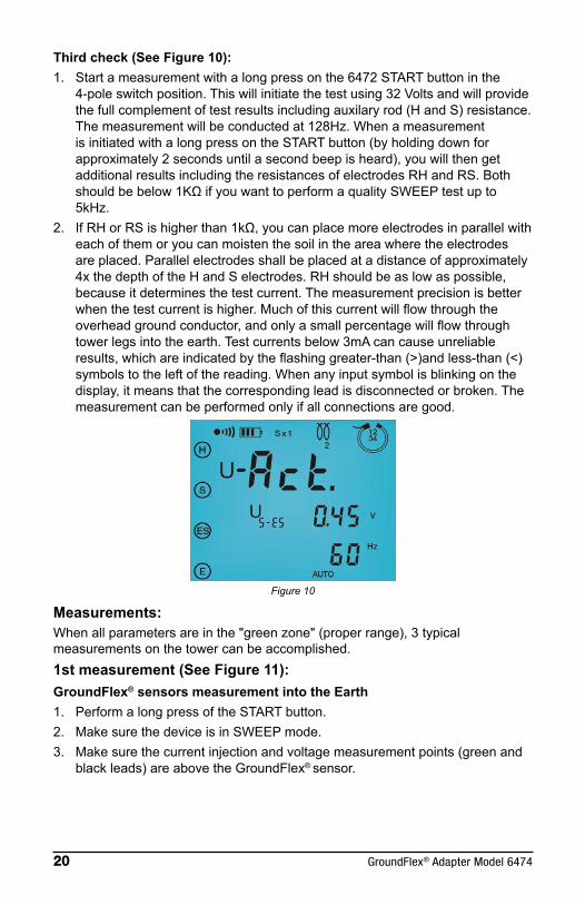
Third check (See Figure 10):1. Startameasurementwithalongpressonthe6472STARTbuttoninthe
4-poleswitchposition.Thiswillinitiatethetestusing32Voltsandwillprovidethefullcomplementoftestresultsincludingauxilaryrod(HandS)resistance.Themeasurementwillbeconductedat128Hz.WhenameasurementisinitiatedwithalongpressontheSTARTbutton(byholdingdownforapproximately2secondsuntilasecondbeepisheard),youwillthengetadditionalresultsincludingtheresistancesofelectrodesRHandRS.Bothshouldbebelow1KΩifyouwanttoperformaqualitySWEEPtestupto5kHz.
2. IfRHorRSishigherthan1kΩ,youcanplacemoreelectrodesinparallelwitheachofthemoryoucanmoistenthesoilintheareawheretheelectrodesareplaced.Parallelelectrodesshallbeplacedatadistanceofapproximately4xthedepthoftheHandSelectrodes.RHshouldbeaslowaspossible,becauseitdeterminesthetestcurrent.Themeasurementprecisionisbetterwhenthetestcurrentishigher.Muchofthiscurrentwillflowthroughtheoverheadgroundconductor,andonlyasmallpercentagewillflowthroughtowerlegsintotheearth.Testcurrentsbelow3mAcancauseunreliableresults,whichareindicatedbytheflashinggreater-than(>)andless-than(<)symbolstotheleftofthereading.Whenanyinputsymbolisblinkingonthedisplay,itmeansthatthecorrespondingleadisdisconnectedorbroken.Themeasurementcanbeperformedonlyifallconnectionsaregood.
Figure 10
Measurements:Whenallparametersareinthe"greenzone"(properrange),3typicalmeasurementsonthetowercanbeaccomplished.1st measurement (See Figure 11):GroundFlex® sensors measurement into the Earth1. PerformalongpressoftheSTARTbutton.2. MakesurethedeviceisinSWEEPmode.3. Makesurethecurrentinjectionandvoltagemeasurementpoints(greenand
blackleads)areabovetheGroundFlex® sensor.

GroundFlex® Adapter Model 6474 21
Figure 11
2nd measurement (See Figure 12):GroundFlex® sensor measurement into static wire (overhead ground conductor)1. MakesurethedeviceisinSWEEPMode.2. MovethecurrentinjectionwireE(green)soitfeedsthroughtheGroundFlex®
sensorsonthetowerlegandconnectsnexttothepotentialconnection.3. DonotmovetheES(black)potentialconnection.
Figure 12
NOTE:InSWEEPmodealongpressisautomaticalyinitiatedandthemeasurementsateachfrequencyusedinthesweeparestoredinmemory
Third measurement (See Figure 13):4-pole Earth-impedance measurement (lattice network measurement) 1. MakesurethedeviceisinSWEEPMode.2. 4-poleEarth-impedancemeasurement(sometimescalled"latticenetwork"
measurement).3. Inthiscase,thetotalearthimpedanceofallcomponentsofthegrounding
systemasifitisoneresistance/impedancewillbemeasured.

22 GroundFlex® Adapter Model 6474
4. Theoverheadgroundconductor(OGC)connectsthegroundingsystemsofalltowersinparallelatlowfrequencies,butathigherfrequenciestheinductanceoftheOGCstartstoseparatethemsuchthattheeffectiveimpedenceofanindividualtowercaneffectivelybemeasured.
5. Measuretheresistance/impedancein10%incrementsbetweenEandH.6. Lookfortheplateaureadings(usuallybetween50%and70%distancesto
findtheeffectiveresistance/impedanceofthestructureundertest.
Figure 13First check1. MeasuredisturbancevoltagesUACT,US-ES,andUH-E.WhenUS-ESand
UH-Earecloseinvaluetoeachother,thentheHandSelectrodesarefarenoughawayfromtheHVline.Iftheyaredifferent,movetheelectrodewiththelowervoltagefurtherawayfromtheHVlineandrecheck.WhenUS-ESandUH-Eareclosetoorequaltozero,theOGCiseitherbadlycorrodedordisconnected.
2. Next,checkRPASSandnoteitforlateruse.Second check1. Checkthecurrentineachtowerleg(IACT/ISEL)tofindcorrodedor
disconnectedgroundingpoints.(break)Ifthesumofalllegsisapproximatelythesameasthesumofallindividuallegs,thentheOGCisintact.
Third check1. PresstheSTARTbuttonwithalongpresstobeginactivemeasurements.
NotetheresistanceofRHandRS.2. Ifeitherorbothareabove1kΩ,addmoreelectrodesormoistenthesoil
aroundthemtolowertheirresistancetoEarth.3. 1stMeasurement:useSWEEPmodewiththeblackandgreenwires
connectedtothetowerlegabovetheGroundFlex® sensor4. 2ndMeasurement:usetheSWEEPmodewiththeblackwireconnectedto
thetowerlegabovetheGroundFlex®sensorandthegreenwireconnectedtothetowerlegnexttotheblackleadandpassingthroughtheGroundFlex® sensor.
5. 3rdMeasurement:usetheSWEEPmodetoperforma4-poleimpedencemeasurement.

GroundFlex® Adapter Model 6474 23
GlossaryE Terminal:isagreencoloredterminalandisthecurrentinjectorterminal.ItisalsoknownastheXterminalES Terminal:isablackcoloredterminalandisthevoltagemeasurementterminal.ItisalsoknownastheXvterminal.S Terminal:isabluecoloredterminalandisthevoltagereturnterminal.ItisalsoknownastheYterminal.H Terminal:isaredcoloredterminalandisthecurrentreturnterminal.ItisalsoknownastheZterminal.HV Line:isthepowerlinerunningfromtowertotower.Top Line:istheoverheadgroundconductoralsoknownastheskywireinsomeareas.UACT:isthereal-timevoltagemeasuredbeforerunningatestISEL:isthetotalreal-timeleakagecurrentmeasuredRPASS:isthepassiveearthresistancemeasuredatnormalnetworkfrequency.SWEEP Mode:isameasurementmodewherethe6472takesmeasurementsat14userselectedfrequenciesbetween40and5078Hz.4-Pole:referstothenumberofterminalsonthe6472usedinperformingatest.Green Zone:referstoallconditionsbeingwithinrangetoproperlytakemeasurementsGroundFlex® Sensor:alsoknownasAmpFlexSensororRogowskicoilwhichisaflexibledeviceusedtomeasureACcurrentflow.U: usedastheinternationalsymbolforVolts.US-ES: Voltagemeasuredatthepotentialterminals.UH-E:VoltagemeasuredattheinjectionterminalsRH:ResistanceoftheinjectorelectrodeRS:ResistanceofthepotentialelectrodeOGC:usedasatermtoindicatetheoverheadgroundconductoralsocalledstaticwireorskywireGreen Zone Conditions:RH and RS: Resistanceofeachshouldbelessthan1kΩifeitherorbothareabovethataddmoreauxliaryelectrodesinparrallelormoistentheareaaroundtheelectrode.I-ACT:Thismeasurementshouldbeaminimumof3milliAmpsUS-ES and UH-E:Thevoltagemeasurementsfortheseshouldbeclosetoeachother.Iftheyarenotwithinafewvoltsofeachother,movetheauxiliaryrodwiththelowervaluefurtherfromtheHVlineandretest.

24 GroundFlex® Adapter Model 6474
CHAPTER 3
SPECIFICATIONS
3.1 ElectricalMeasuring Method:Voltage/CurrentmeasurementwitharectangularACsignal
Short Circuit Current:>200mAAC
Noise Suppression: >80dBatfrequenciesdifferingby20%ormorefromthetestfrequency
Max. Overload: 250Vrms
Max. Value for RH & RS: 100kΩ
Measuring Time: Short push on START: approx.7sforfirstvalueofRE at 128Hz,then3measurementspers.
Long push on START:approx.15sforfirstvalueofRE at 128Hz,then3measurementspers.
Pylon Measurement with GroundFlex®
Measurement Range
0.067 to 9.999Ω
10.00 to 99.99Ω
100.0 to 999.9Ω
1.000 to 9.999kΩ
10.00 to 99.99kΩ
Resolution 0.001Ω 0.01Ω 0.1Ω 1Ω 10Ω
Test Voltage16 or 32V user selectable (10, 16, 32, or 60V for meters manufactured
after August 2019) square wave(if current > 240mA the output voltage is reduced to 10V)
Frequency From 41 to 128Hz selectable
Resistance Measurement Frequency From 41 to 5078Hz selectable
Accuracy ±5% of Reading + 1ct @ 128Hz
The intrinsicerrorspecified refers to referenceconditionswitha testvoltageof32V,testfrequencyof128Hz,RH,andRS=1kΩ,noexternalvoltage.
The operating error for measurements of RH, RS and RE is the same as thatspecifiedfor4-Poleearthresistancemeasurement.

GroundFlex® Adapter Model 6474 25
TheoperatingerrorofACresistancemeasurementscanbelessthanthatspecifiedforvoltageorcurrentbecausefrequencycharacteristicsofthevoltagechannelarematchedtothoseofthecurrentchannel.
For test frequencies between 41 and 5087Hz, between 1 and 4 turns of theGroundFlex® sensor, and a selection of 1 to 4 measurement channels, theoperatingaccuraciesarethefollowing:
SENSITIVITY and minimum ISEL minimal Operating accuracy for RS-ES
S x 1/10 ISEL > 10mA ± (10% + 4cts)
S x 1 ISEL > 5mA ± (5% + 4cts)
S x 10ISEL > 5mA ± (5% + 4cts)
5mA > ISEL > 0.5mA ± (15% + 10cts)
Current Measurement with GroundFlex®
Measurement Range 0.0 to 99.9mA (1)
100 to999mA
1.00 to9.99A
10.0 to99.9A
Resolution 0.1mA (1) 1mA 0.01A 0.1A
Frequency 16 to 400Hz
Accuracy <5% of Reading @ 50/60Hz
(1): Valid only in the SENSITIVITY x 10 setting
ThecurrentmeasureddependsonthenumberofturnsoftheGroundFlex® sensor aroundtheconductortobemeasured.(e.g.if the GroundFlex® sensor is wrapped 4 times around a conductor carrying a current of 1A, the input signal will be the same as if the GroundFlex® sensor were wrapped once around a conductor carrying a current of 4A. The operating error is therefore indicated for an input signal current in A.tr (Ampere.turns).
The minimum current measured depends on the setting of the SENSITIVITYswitchasindicatedbythetablebelow:
SENSITIVITY IMIN (A.tr) Points additional error (pt-er)
x 10 0.01 5
x 1 0.04 2
x 1/10 0.16 2
Accuracy Current (A * turn) 16 to 49Hz 50 to 99Hz 100 to 400Hz
IMIN to 0.399 ± (20% + pt-er) ± (5% + pt-er) ± (3% + pt-er)
0.4 to 39.9 ± (10% + 2ct) ± (3% + 2ct) ± (3% + 2ct)
40 to 99.9 ± (10% + 2ct) ± (3% + 2ct) ± (20% + 2ct)

26 GroundFlex® Adapter Model 6474
3.2 MechanicalDimensions:10.7x9.76x5.12"(272,248x130mm)
Weight: 7lbs(3.2kg)approx
Case Material:ULV0Polypropylene
Terminals: 4mmrecessedbananajacks
Case Protection: EN60529-IP53(coverclosed)
Drop Test: PerEN61010-1
Vibration Test: PerEN61557-1
3.3 EnvironmentalOperating Temperature: 32°to113°F(0°to45°C);0to90%RH
Specified Operating Temperature(1):0°to95°F(0°to35°C);0to75%RH
Storage Temperature:-40°to158°F(-40°to70°C);0to90%RH
Altitude: <3000m
(1): This range corresponds to the one defined by standard EN 61557, for which an operating error including the quantities of influence is defined. When the device is used outside this range, 1.5%/10°C and 1.5% between 75 and 90% RH must be added to the operating error.
3.4 SafetyElectromagnetic CompatibilityThisinstrumentsatisfiestheEMCandLVDdirectivesrequiredfortheCEmarkingandproductstandardIEC61326-1(Ed.97)+A1(Ed.98).
• Immunityinindustrialenvironment• Emissions in residential environment.
ElectricalsafetyaccordingtoEN61010-1(Ed.2of2001)
MeasurementaccordingtoEN61557(Ed.2of2007)parts1,4and5.
CATIV,50V
PollutionDegree2
*Specifications are subject to change without notice

GroundFlex® Adapter Model 6474 27
CHAPTER 4
MAINTENANCE
4.1 Maintenance
Please make sure that you have read and fully understand the WARNING section on page 3.
• Toavoidelectricalshock,donotattempt toperformanyservicingunlessyouarequalifiedtodoso.
• Toavoidelectricalshockand/ordamagetotheinstrument,donotgetwaterorotherforeignagentsintothecase.
• Turn the instrumentOFFand disconnect the unit fromall circuits beforeopeningthecase.
• Usespecifiedsparepartsonly.
4.2 Cleaning
Disconnect the instrument from any source of electricity.
Useasoftclothlightlymoistenedwithsoapywater.Wipewithamoistclothandthendrywithadrycloth.Neverusealcohol,solventsorhydrocarbons.

28 GroundFlex® Adapter Model 6474
Repair and Calibration
Toensurethatyourinstrumentmeetsfactoryspecifications,werecommendthatitbescheduledbacktoourfactoryServiceCenteratone-yearintervalsforrecalibration,orasrequiredbyotherstandardsorinternalprocedures.
For instrument repair and calibration:YoumustcontactourServiceCenterforaCustomerServiceAuthorizationNumber(CSA#).Thiswillensurethatwhenyourinstrumentarrives,itwillbetrackedandprocessedpromptly.PleasewritetheCSA#ontheoutsideoftheshippingcontainer.Iftheinstrumentisreturnedforcalibration,weneedtoknowifyouwantastandardcalibration,oracalibrationtraceabletoN.I.S.T.(Includescalibrationcertificateplusrecordedcalibrationdata).
Ship To: ChauvinArnoux®,Inc.d.b.a.AEMC®Instruments 15 Faraday Drive Dover,NH03820USA Phone:(800)945-2362(Ext.360) (603)749-6434(Ext.360) Fax: (603)742-2346or(603)749-6309 E-mail:[email protected],standardcalibration,andcalibrationtraceabletoN.I.S.T.areavailable.NOTE: You must obtain a CSA# before returning any instrument.
Technical and Sales Assistance
Ifyouareexperiencinganytechnicalproblems,orrequireanyassistancewiththeproperoperationorapplicationofyourinstrument,pleasecall,mail,faxore-mailourtechnicalsupportteam:
ChauvinArnoux®,Inc.d.b.a.AEMC®Instruments 15 Faraday Drive Dover,NH03820USA Phone:(800)945-2362(Ext.351) (603)749-6434(Ext.351) Fax: (603)742-2346or(603)749-6309 E-mail:[email protected] www.aemc.com

GroundFlex® Adapter Model 6474 29
Limited Warranty
TheModel6474iswarrantedtotheownerforaperiodofthreeyearsfromthedateoforiginalpurchaseagainstdefectsinmanufacture.ThislimitedwarrantyisgivenbyAEMC®Instruments,notbythedistributorfromwhomitwaspurchased.Thiswarrantyisvoidiftheunithasbeentamperedwith,abusedorifthedefectisrelatedtoservicenotperformedbyAEMC® Instruments.
For full and detailed warranty coverage, please read the Warranty Coverage Information, which is attached to the Warranty Registration Card (if enclosed) or is available at www.aemc.com. Please keep the Warranty Coverage Information with your records.
What AEMC® Instruments will do:Ifamalfunctionoccurswithinthewarrantyperiod,youmayreturntheinstrumenttousforrepair,providedwehaveyourwarrantyregistrationinformationonfileoraproofofpurchase.AEMC®Instrumentswill,atitsoption,repairorreplacethefaultymaterial.
REGISTER ONLINE AT:www.aemc.com
Warranty Repairs
What you must do to return an Instrument for Warranty Repair: First,requestaCustomerServiceAuthorizationNumber(CSA#)byphoneorbyfaxfromourServiceDepartment(seeaddressbelow),thenreturntheinstrumentalongwiththesignedCSAForm.PleasewritetheCSA#ontheoutsideoftheshippingcontainer.Returntheinstrument,postageorshipmentpre-paidto:
Ship To: ChauvinArnoux®,Inc.d.b.a.AEMC®Instruments 15FaradayDrive•Dover,NH03820USA Phone:(800)945-2362(Ext.360) (603)749-6434(Ext.360) Fax: (603)742-2346or(603)749-6309 E-mail:[email protected]
Caution:Toprotectyourselfagainstin-transitloss,werecommendyouinsureyourreturnedmaterial.
NOTE: You must obtain a CSA# before returning any instrument.

Notes:

12/21
99-MAN100326v9
Chauvin Arnoux®, Inc. d.b.a. AEMC® Instruments15FaradayDrive•Dover,NH03820USA•Phone:(603)749-6434•Fax:(603)742-2346
www.aemc.com