advertising supplement the perfect setup - freud …€¦ · check the corner miter on the two...
TRANSCRIPT
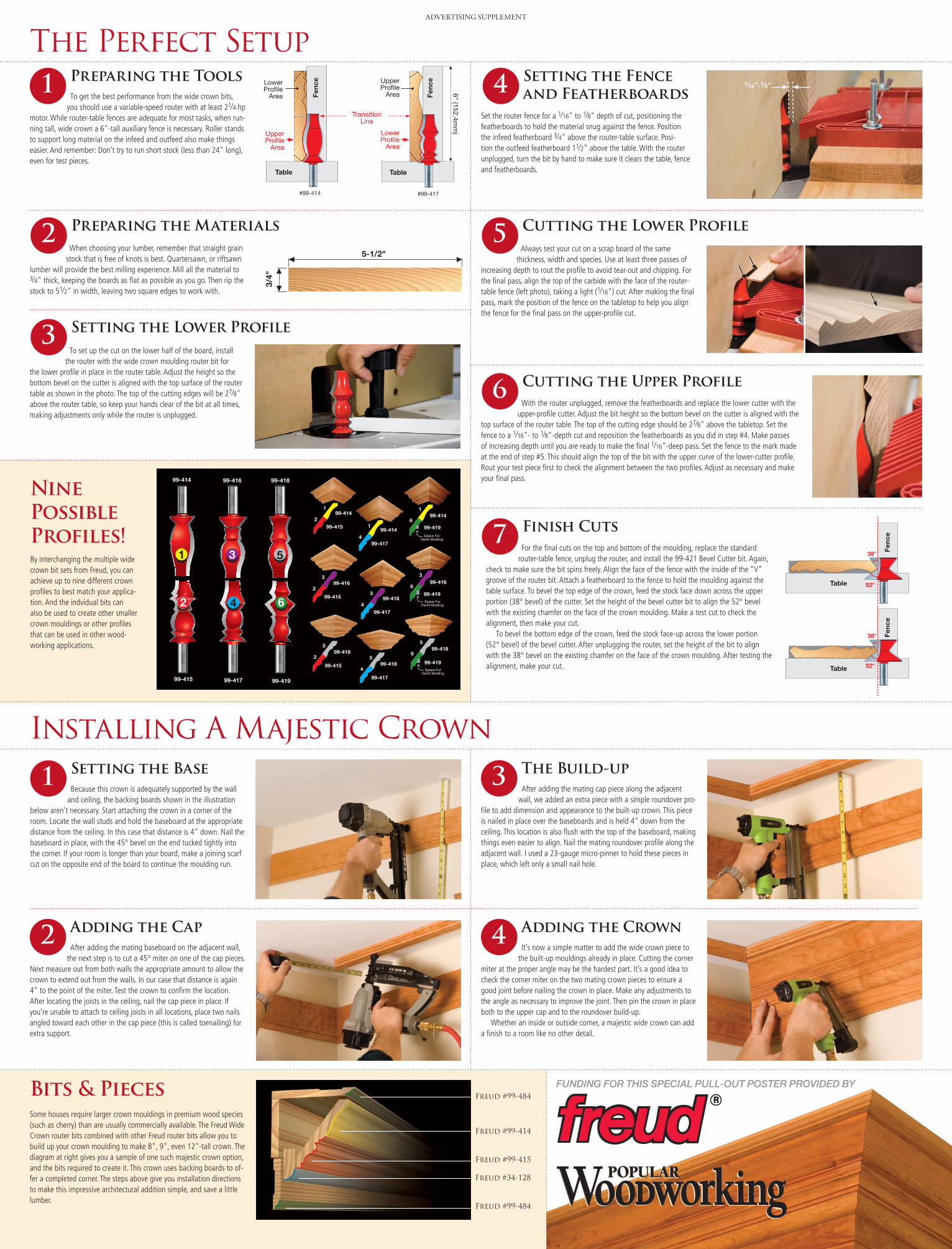
Preparing the Tools To get the best performance from the wide crown bits,
you should use a variable-speed router with at least 21⁄4-hp motor. While router-table fences are adequate for most tasks, when run-ning tall, wide crown a 6"-tall auxiliary fence is necessary. Roller stands to support long material on the infeed and outfeed also make things easier. And remember: Don’t try to run short stock (less than 24" long), even for test pieces.
Preparing the Materials When choosing your lumber, remember that straight grain
stock that is free of knots is best. Quartersawn, or riftsawn lumber will provide the best milling experience. Mill all the material to 3⁄4" thick, keeping the boards as flat as possible as you go. Then rip the stock to 51⁄2" in width, leaving two square edges to work with.
Setting the Lower Profile
Setting the Fence and Featherboards
Cutting the Lower Profile
Cutting the Upper Profile
Finish Cuts
funding for this special pull-out poster provided by
ADVERTISING SUPPLEMENT
®
®
LowerProfile
Area
UpperProfile
Area
LowerProfile
Area
UpperProfile
Area
TransitionLine
6" (152.4mm
)
#99-414
Fenc
e
Table
Fenc
e
Table
#99-417
5-1/2"
3/4"
Fenc
e
Table
®
52°
38°
Fenc
e
Table
®
52°
38°
The Perfect Setup
Installing A Majestic Crown
To set up the cut on the lower half of the board, install the router with the wide crown moulding router bit for
the lower profile in place in the router table. Adjust the height so the bottom bevel on the cutter is aligned with the top surface of the router table as shown in the photo. The top of the cutting edges will be 27⁄8" above the router table, so keep your hands clear of the bit at all times, making adjustments only while the router is unplugged.
Set the router fence for a 1⁄16" to 1⁄8" depth of cut, positioning the featherboards to hold the material snug against the fence. Position the infeed featherboard 3⁄4" above the router-table surface. Posi-tion the outfeed featherboard 11⁄2" above the table. With the router unplugged, turn the bit by hand to make sure it clears the table, fence and featherboards.
Always test your cut on a scrap board of the same thickness, width and species. Use at least three passes of
increasing depth to rout the profile to avoid tear-out and chipping. For the final pass, align the top of the carbide with the face of the router-table fence (left photo), taking a light (1⁄16") cut. After making the final pass, mark the position of the fence on the tabletop to help you align the fence for the final pass on the upper-profile cut.
With the router unplugged, remove the featherboards and replace the lower cutter with the upper-profile cutter. Adjust the bit height so the bottom bevel on the cutter is aligned with the
top surface of the router table. The top of the cutting edge should be 27⁄8" above the tabletop. Set the fence to a 1⁄16"- to 1⁄8"-depth cut and reposition the featherboards as you did in step #4. Make passes of increasing depth until you are ready to make the final 1⁄16"-deep pass. Set the fence to the mark made at the end of step #5. This should align the top of the bit with the upper curve of the lower-cutter profile. Rout your test piece first to check the alignment between the two profiles. Adjust as necessary and make your final pass.
For the final cuts on the top and bottom of the moulding, replace the standard router-table fence, unplug the router, and install the 99-421 Bevel Cutter bit. Again,
check to make sure the bit spins freely. Align the face of the fence with the inside of the “V” groove of the router bit. Attach a featherboard to the fence to hold the moulding against the table surface. To bevel the top edge of the crown, feed the stock face down across the upper portion (38° bevel) of the cutter. Set the height of the bevel cutter bit to align the 52° bevel with the existing chamfer on the face of the crown moulding. Make a test cut to check the alignment, then make your cut.
To bevel the bottom edge of the crown, feed the stock face-up across the lower portion (52° bevel) of the bevel cutter. After unplugging the router, set the height of the bit to align with the 38° bevel on the existing chamfer on the face of the crown moulding. After testing the alignment, make your cut.
Nine Possible Profiles!By interchanging the multiple wide crown bit sets from Freud, you can achieve up to nine different crown profiles to best match your applica-tion. And the indvidual bits can also be used to create other smaller crown mouldings or other profiles that can be used in other wood-working applications.
1
2
3
4
5
6
7
1⁄16"-1⁄8"
Setting the Base Because this crown is adequately supported by the wall
and ceiling, the backing boards shown in the illustration below aren’t necessary. Start attaching the crown in a corner of the room. Locate the wall studs and hold the baseboard at the appropriate distance from the ceiling. In this case that distance is 4" down. Nail the baseboard in place, with the 45° bevel on the end tucked tightly into the corner. If your room is longer than your board, make a joining scarf cut on the opposite end of the board to continue the moulding run.
1
Adding the Cap After adding the mating baseboard on the adjacent wall,
the next step is to cut a 45° miter on one of the cap pieces. Next measure out from both walls the appropriate amount to allow the crown to extend out from the walls. In our case that distance is again 4" to the point of the miter. Test the crown to confirm the location. After locating the joists in the ceiling, nail the cap piece in place. If you’re unable to attach to ceiling joists in all locations, place two nails angled toward each other in the cap piece (this is called toenailing) for extra support.
2
The Build-up After adding the mating cap piece along the adjacent
wall, we added an extra piece with a simple roundover pro-file to add dimension and appearance to the built-up crown. This piece is nailed in place over the baseboards and is held 4" down from the ceiling. This location is also flush with the top of the baseboard, making things even easier to align. Nail the mating roundover profile along the adjacent wall. I used a 23-gauge micro-pinner to hold these pieces in place, which left only a small nail hole.
3
Adding the Crown It’s now a simple matter to add the wide crown piece to
the built-up mouldings already in place. Cutting the corner miter at the proper angle may be the hardest part. It’s a good idea to check the corner miter on the two mating crown pieces to ensure a good joint before nailing the crown in place. Make any adjustments to the angle as necessary to improve the joint. Then pin the crown in place both to the upper cap and to the roundover build-up.
Whether an inside or outside corner, a majestic wide crown can add a finish to a room like no other detail.
4
Some houses require larger crown mouldings in premium wood species (such as cherry) than are usually commercially available. The Freud Wide Crown router bits combined with other Freud router bits allow you to build up your crown moulding to make 8", 9", even 12"-tall crown. The diagram at right gives you a sample of one such majestic crown option, and the bits required to create it. This crown uses backing boards to of-fer a completed corner. The steps above give you installation directions to make this impressive architectural addition simple, and save a little lumber.
Freud #99-484
Freud #99-414
Freud #34-128
Freud #99-415
Freud #99-484
99-414
99-415 99-414
99-417
99-414
99-419
99-416
99-415 99-416
99-417
99-416
99-419
99-418
99-415 99-418
99-417
99-418
99-419
®
99-414 99-416
®
99-418
®
®
99-415 99-417
®
99-419
®
Space ForDentil Molding
Space ForDentil Molding
Space ForDentil Molding
1 3 5
2 4 6
1
21
4
1
6
3
23
4
3
6
5
2 5
4
5
6
Bits & Pieces