advances in structural engineering state-of-the-art review
TRANSCRIPT

Article
Advances in Structural Engineering1–17� The Author(s) 2016Reprints and permissions:sagepub.co.uk/journalsPermissions.navDOI: 10.1177/1369433216655922ase.sagepub.com
State-of-the-art review on bridgeweigh-in-motion technology
Yang Yu1, CS Cai1 and Lu Deng2
AbstractWeigh-in-motion technology is an effective tool that has been extensively used to monitor traffic on highways. Pavement-based weigh-in-motion systems usually have poor durability and will cause traffic interruption during their installation and maintenance process.The recently developed bridge weigh-in-motion technology provides a more convenient and cost-effective alternative to thepavement-based weigh-in-motion technology. Bridge weigh-in-motion systems can be installed without interrupting the traffic. Also,bridge weigh-in-motion systems have the potential to deliver better accuracy than pavement-based weigh-in-motion systems. Due tothese significant advantages, the bridge weigh-in-motion technology has been playing an increasingly important role in bridge healthmonitoring and overweight truck enforcement, and many studies have been conducted to continuously improve the bridge weigh-in-motion technology. In this review, the common algorithms for bridge weigh-in-motion are discussed in detail, and the typical instru-mentation of bridge weigh-in-motion systems is also introduced. Meanwhile, much effort is made to identify the remaining issues inthe application of bridge weigh-in-motion technology, and the corresponding future research is proposed.
Keywordsaxle detection, bridge weigh-in-motion, instrumentation, moving force identification, strain measurement, weigh-in-motion
Introduction
Vehicle overloading has become a common issue thathas raised serious concerns worldwide (Fu and Hag-Elsafi, 2000). Overweight trucks can lead to seriousdamages and accelerate the degradation of road infra-structures. The most common issue is the fatigue prob-lems of bridge components, which can significantlyshorten the service life of bridges (Biezma andSchanack, 2007; Wardhana and Hadipriono, 2003). Insome extreme cases, the weight of the overloaded truckmay even exceed the load-carrying capacity of thebridge and directly cause the bridge to collapse.Moreover, overloaded trucks have higher risks of beinginvolved in traffic accidents (Jacob and Beaumelle,2010). In light of these concerns, overweight truckenforcement has become increasingly important for theprotection and maintenance of modern transportationsystems.
The common techniques used to weigh highwaytrucks include static weighing techniques and weigh-in-motion (WIM) techniques. While static weighing canbe very accurate, it is costly and time-consuming toimplement, and therefore, it is impractical for trans-portation systems with heavy truck traffic. To over-come the limitations of static weighing, pavement-based WIM technologies have been developed since
the 1960s (Richardson et al., 2014). Pavement-basedWIM systems use devices installed on the road toweigh highway vehicles under normal traffic condi-tions. The common devices used for pavement-basedWIM systems include bending plates, load cells, capa-citance mats, and strip sensors.
Moses (1979) first proposed the concept of bridgeweigh-in-motion (BWIM). Unlike the pavement-basedWIM techniques, the BWIM techniques use an instru-mented bridge as the weighing scale to estimate thevehicle weights. In the Moses’ algorithm, the axleweight is predicted by minimizing the differencebetween the measured bridge response and the pre-dicted bridge response which is computed using theinfluence line concept. The Moses’ algorithm has beenused to establish the basic framework for modern com-mercial BWIM systems. In the 1980s, Peters (1984)developed the Axway system in Australia. Later,
1Department of Civil & Environmental Engineering, Louisiana State
University, Baton Rouge, LA, USA2College of Civil Engineering, Hunan University, Changsha, China
Corresponding author:
CS Cai, Department of Civil & Environmental Engineering, Louisiana
State University, Baton Rouge, LA 70803, USA.
Email: [email protected]

Peters (1986) developed a more effective system knownas the Culway which uses a culvert as the weighingscale. The reason for using a culvert rather than abridge is that the dynamic effects caused by the interac-tion between the vehicle and the culvert can be morequickly dampened out by the surrounding soil. InEurope, the COST 323 action (COST 323, 2002) andWAVE project (WAVE, 2001) were carried out in thelate 1990s. These projects brought significant improve-ments to the accuracy of the BWIM techniques and ledto the development of a well-known commercial BWIMsystem known as the SiWIM system. In recent years,much effort has been made to continuously improve theaccuracy of the existing algorithms and to develop novelalgorithms to extend the applicability of BWIM tech-nologies. Lydon et al. (2015) provided a general reviewon the BWIM theory and critical issues emerged duringthe current practice along with detailed case studies ofBWIM applications. The review presented herein willfocus more on the technical aspects of the BWIM tech-nology including the fundamental methodologies andthe field implementation of BWIM systems.
BWIM systems have several advantages over thepavement-based WIM systems. First, BWIM systemsare more durable than pavement-based WIM systems,since most sensors in BWIM systems are installedunder the bridge, which avoids the direct exposure ofsensors to the traffic. Additionally, the installation ofBWIM systems is easy and safe as it can be done with-out interrupting traffic. Furthermore, BWIM systemsare more accurate than pavement-based WIM systems.This is because the contact time between vehicle wheelsand pavement-based WIM sensors, usually at a fewmilliseconds, is not sufficient to record a completecycle of the axle force oscillation. This could easilyresult in under- or overestimation of the axle weights,since the dynamic axle force may significantly deviatefrom the static weight, especially under a rough surfaceprofile (O’Brien et al., 1999). BWIM systems, on theother hand, record the complete time history of thebridge response, based on which a complete cycle ofthe varying axle force can usually be obtained. Thisenables a more accurate calculation of axle weightsthrough proper post-processing. All these advantageshave made BWIM systems a superior tool for over-weight truck enforcement.
This article is intended to present a comprehensivereview on the BWIM technologies. The BWIM algo-rithms, which are classified into the static algorithmsand the dynamic algorithms, are first reviewed indetail, and different algorithms are compared. Then,the typical instrumentation for a BWIM system isintroduced focusing on the sensors for strain measure-ments and techniques for axle detections. Finally, con-clusions are drawn based on the recent advances and
suggestions that are provided for future research in thefield of BWIM technologies.
BWIM algorithms
Generally speaking, BWIM algorithms can be dividedinto two broad categories, that is, the static algorithmsthat aim at obtaining the static axle weight and thedynamic algorithms that seek to obtain the time his-tory of axle forces. The static algorithms include theMoses’ algorithm, the influence area method, the reac-tion force method, and the orthotropic BWIM algo-rithm. The dynamic algorithms are also known as themoving force identification (MFI) methods.
Moses’ algorithm
Moses (1979) proposed the first BWIM algorithm for abeam-slab bridge. For this type of bridges, the measuredbending moment at time step k can be obtained by sum-ming the individual bending moment of each girder:
Mmk =
XG
i
ESiei ð1Þ
where G is the total number of girders, E is the modu-lus of elasticity, Si is the section modulus of the ith gir-der, and ei is the measured strain in the ith girder.Meanwhile, the predicted bending moment at time stepk can be obtained using the influence line concept as:
Mpk =
XN
i= 1
AiIi, (k�Ci) ð2Þ
Ci =Dif
vð3Þ
where N is the number of axles, Ai is the weight of theith axle, Ii, (k�Ci) is the influence ordinate at the positionof the ith axle, Di is the distance between the first axleand ith axle, Ci is the number of scans correspondingto Di, f is the sampling frequency of the BWIM system,and v is the vehicle speed which is assumed to be a con-stant as the vehicle travels on the bridge. The errorfunction for the total number of step T is defined as:
E =XT
k = 1
(Mpk �Mm
k )2 ð4Þ
To minimize the error function, the least-squaresmethod is used. The partial derivative with respect tothe axle weight is set to 0:
∂E
∂Aj
= 2XT
k = 1
(Mpk �Mm
k )∂(M
pk �Mm
k )
∂Aj
= 0 ð5Þ
2 Advances in Structural Engineering
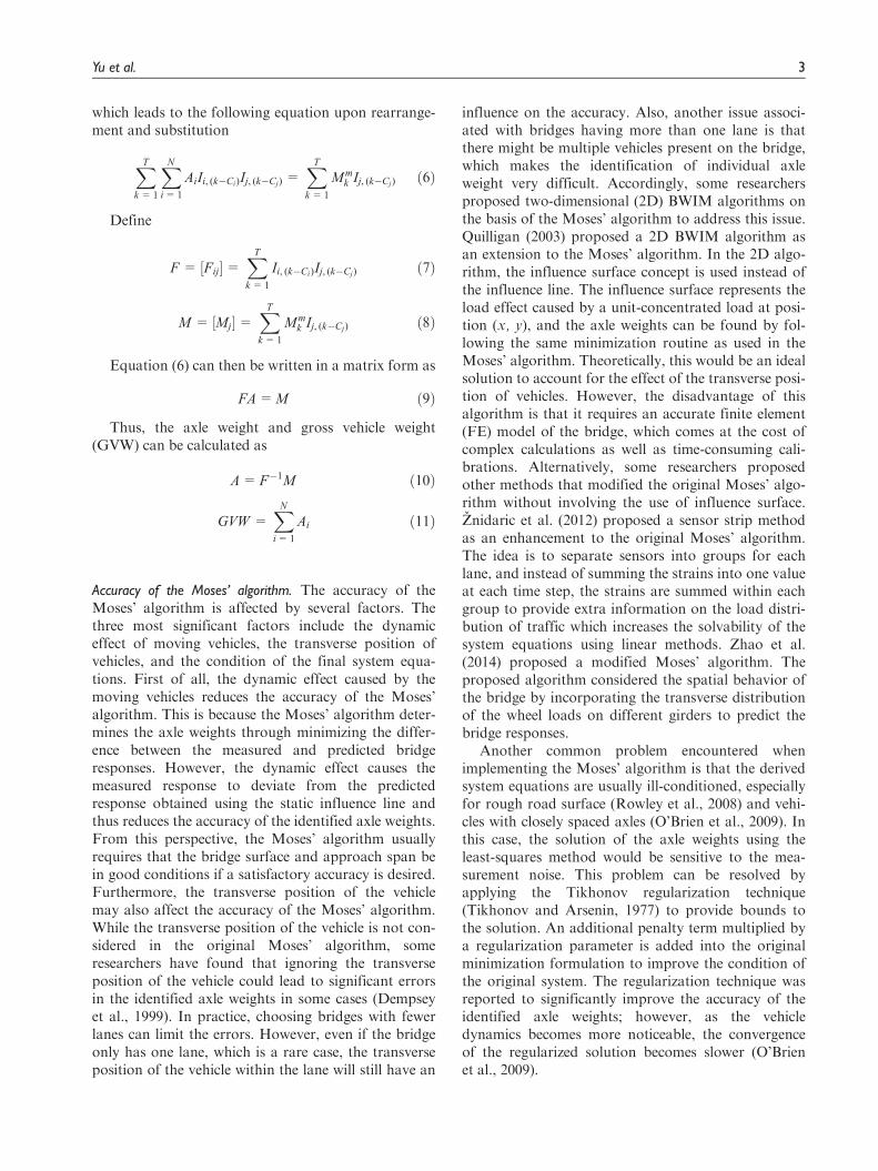
which leads to the following equation upon rearrange-ment and substitution
XT
k = 1
XN
i= 1
AiIi, (k�Ci)Ij, (k�Cj) =XT
k = 1
Mmk Ij, (k�Cj) ð6Þ
Define
F = ½Fij�=XT
k = 1
Ii, (k�Ci)Ij, (k�Cj) ð7Þ
M = ½Mj�=XT
k = 1
Mmk Ij, (k�Cj) ð8Þ
Equation (6) can then be written in a matrix form as
FA=M ð9Þ
Thus, the axle weight and gross vehicle weight(GVW) can be calculated as
A=F�1M ð10Þ
GVW =XN
i= 1
Ai ð11Þ
Accuracy of the Moses’ algorithm. The accuracy of theMoses’ algorithm is affected by several factors. Thethree most significant factors include the dynamiceffect of moving vehicles, the transverse position ofvehicles, and the condition of the final system equa-tions. First of all, the dynamic effect caused by themoving vehicles reduces the accuracy of the Moses’algorithm. This is because the Moses’ algorithm deter-mines the axle weights through minimizing the differ-ence between the measured and predicted bridgeresponses. However, the dynamic effect causes themeasured response to deviate from the predictedresponse obtained using the static influence line andthus reduces the accuracy of the identified axle weights.From this perspective, the Moses’ algorithm usuallyrequires that the bridge surface and approach span bein good conditions if a satisfactory accuracy is desired.Furthermore, the transverse position of the vehiclemay also affect the accuracy of the Moses’ algorithm.While the transverse position of the vehicle is not con-sidered in the original Moses’ algorithm, someresearchers have found that ignoring the transverseposition of the vehicle could lead to significant errorsin the identified axle weights in some cases (Dempseyet al., 1999). In practice, choosing bridges with fewerlanes can limit the errors. However, even if the bridgeonly has one lane, which is a rare case, the transverseposition of the vehicle within the lane will still have an
influence on the accuracy. Also, another issue associ-ated with bridges having more than one lane is thatthere might be multiple vehicles present on the bridge,which makes the identification of individual axleweight very difficult. Accordingly, some researchersproposed two-dimensional (2D) BWIM algorithms onthe basis of the Moses’ algorithm to address this issue.Quilligan (2003) proposed a 2D BWIM algorithm asan extension to the Moses’ algorithm. In the 2D algo-rithm, the influence surface concept is used instead ofthe influence line. The influence surface represents theload effect caused by a unit-concentrated load at posi-tion (x, y), and the axle weights can be found by fol-lowing the same minimization routine as used in theMoses’ algorithm. Theoretically, this would be an idealsolution to account for the effect of the transverse posi-tion of vehicles. However, the disadvantage of thisalgorithm is that it requires an accurate finite element(FE) model of the bridge, which comes at the cost ofcomplex calculations as well as time-consuming cali-brations. Alternatively, some researchers proposedother methods that modified the original Moses’ algo-rithm without involving the use of influence surface.Znidaric et al. (2012) proposed a sensor strip methodas an enhancement to the original Moses’ algorithm.The idea is to separate sensors into groups for eachlane, and instead of summing the strains into one valueat each time step, the strains are summed within eachgroup to provide extra information on the load distri-bution of traffic which increases the solvability of thesystem equations using linear methods. Zhao et al.(2014) proposed a modified Moses’ algorithm. Theproposed algorithm considered the spatial behavior ofthe bridge by incorporating the transverse distributionof the wheel loads on different girders to predict thebridge responses.
Another common problem encountered whenimplementing the Moses’ algorithm is that the derivedsystem equations are usually ill-conditioned, especiallyfor rough road surface (Rowley et al., 2008) and vehi-cles with closely spaced axles (O’Brien et al., 2009). Inthis case, the solution of the axle weights using theleast-squares method would be sensitive to the mea-surement noise. This problem can be resolved byapplying the Tikhonov regularization technique(Tikhonov and Arsenin, 1977) to provide bounds tothe solution. An additional penalty term multiplied bya regularization parameter is added into the originalminimization formulation to improve the condition ofthe original system. The regularization technique wasreported to significantly improve the accuracy of theidentified axle weights; however, as the vehicledynamics becomes more noticeable, the convergenceof the regularized solution becomes slower (O’Brienet al., 2009).
Yu et al. 3

In addition, it should be mentioned that the accu-racy of a WIM system is usually defined in a statisticalway by the closeness of a measured value to anaccepted reference value, typically within a 95% confi-dence interval (COST 323, 2002). The readers can referto COST 323 (2002) for details on the target accuracylevels for different purposes.
Calibration of influence lines for BWIM systems. For theMoses’ algorithm, the accuracy of the influence line iscritical for the BWIM system to achieve an accurateidentification. When Moses (1979) first proposed theBWIM concept, the theoretical influence line of a sim-ply supported beam was adopted. However, the theore-tical influence line could not accurately predict the realbehavior of the bridge. To reduce the errors caused bythe difference between the theoretical and true influ-ence lines, Znidaric and Baumgartner (1998) proposedan improved theoretical influence line by adjusting thesupport conditions and smoothing the peaks to reachbetter consistency with the real situation. McNulty andO’Brien (2003) proposed a point-by-point graphicalmethod to generate the influence line. However, thismethod has to be executed manually, which means thatits accuracy relies on the skill of the operator. O’Brienet al. (2006) presented a method to generate the influ-ence line from direct measurements. Using the least-squares method, the error function defined in equation(4) is minimized with respect to the influence ordinate,while the axle weights of the calibration vehicle arealready known, and thus, the measured response of aload effect is converted into the influence line of thateffect. This method was verified by field tests and wassuccessfully applied in a BWIM system developed byZhao et al. (2015). However, it should be mentionedthat this method generates the influence line by con-necting discrete points instead of producing a smoothcurve. In order to generate a continuous influence line,some researchers adopted a polynomial function todescribe the influence line, and the optimal coefficientsof the polynomial function are determined by minimiz-ing the error function (Yamaguchi et al., 2009). Ieng(2015) pointed out that the method proposed byO’Brien et al. (2006) is sensitive to perturbations andrevised the method on a probabilistic basis utilizing themaximum likelihood estimation principle. The revisedmethod takes advantage of more signals in the estima-tion of the influence line and thus reduces the errorcaused by the noise in a specific signal.
Orthotropic BWIM algorithm
In the WAVE project (2001), the free-of-axle-detector(FAD) algorithm was initially developed for
orthotropic deck bridges since axle detectors were notallowed on the deck surface in order to maintain thewaterproofing of the deck. The idea of the FAD algo-rithm is to identify the vehicle speed and the axle spac-ing through sensors installed underneath the bridge,where the measured signal shows a sharp peak corre-sponding to each axle passing. For orthotropic deckbridges, the longitudinal stiffeners are usually sup-ported by transverse cross-beams, and the supportedspan is usually short enough so that the strain of thelongitudinal stiffeners will show a peak response corre-sponding to the axle passage, making them suitable forthe FAD algorithm. However, it was also realized thataxle detection using the FAD algorithm would be lessaccurate than that using traditional axle detectors.Therefore, a new identification algorithm, known asthe orthotropic BWIM algorithm, was proposed(WAVE, 2001). This algorithm adopts an optimizationroutine using the conjugate direction methods to mini-mize the objective function in the form of equation (4)and thus finds the best solution of all vehicle para-meters including the vehicle speed, axle spacing, andaxle weights. The identified parameters from the FADalgorithm, including the vehicle speed and the axlespacing, are used as inputs into the optimization pro-cedure, and thus, the new algorithm is less sensitive tothe errors in the initially identified values of vehiclespeed and axle spacing. However, if the objective func-tion is non-convex, there will be multiple solutions forthe vehicle parameters. This would require constraintsbeing applied during the optimization procedure. Inthe WAVE project (2001), it was found that the vehiclespeed cannot exceed 5% of its initial value for the pro-posed algorithm.
It should be mentioned that the Moses’ algorithmcould still be applicable to the orthotropic bridges withsome additional post-processing procedures. Xiaoet al. (2006) instrumented the longitudinal ribs on anorthotropic box girder bridge. The response of thelongitudinal ribs can be divided into a girder compo-nent, that is, the flexural stress due to the rib acting asthe part of the upper flange of the box girder to sup-port the vehicle weight and a rib component, that is,the local stress due to the rib acting as a continuousbeam to support the wheel load. In the axle weight cal-culation, the girder component is first separated fromthe rib component. Then, the Moses’ algorithm isapplied using the rib component to obtain the axleweights.
From the review of the above algorithms, it can beseen that the identification of axle weights through thestatic BWIM algorithms is essentially a mathematicoptimization problem that seeks to minimize the errorfunction which reflects the difference between the mea-sured bridge response and the bridge response
4 Advances in Structural Engineering
reconstructed using the vehicle parameters. In thissense, any optimization method that is capable of mini-mizing the error function of the form given by equation(4) can be used for the BWIM algorithms. In fact, someresearchers have proposed using different optimizationmethods to identify the parameters of vehicles movingon the bridge. Jiang et al. (2004) and Au et al. (2004)proposed a multi-stage optimization scheme based onthe genetic algorithm for the vehicle parameter identifi-cation using the acceleration responses of the bridge.Law et al. (2006) proposed an optimization methodthat makes use of the response sensitivity to indirectlyidentify the vehicle parameters. Deng and Cai (2009)applied the genetic algorithm to identify vehicle para-meters in a full-scale three-dimensional (3D) vehicle-bridge system using different responses of the bridge.They found that the vehicle mass can be identified withvery good accuracy, while some parameters, such asdamping, are difficult to identify due to the measure-ment noise. Pan and Yu (2014) adopted the firefly algo-rithm as the optimization scheme to identify theconstant moving forces. In addition to optimizationmethods, Kim et al. (2009) developed a BWIM algo-rithm based on the artificial neural networks (ANN).The algorithm is formed by two neural networks, thatis, one for the GVW calculation using the signal fromthe weighing sensors and the other for the axle weightcalculation using the signal from the FAD sensors. Thetraining data were acquired from an adjacentpavement-based WIM station. Field tests found thatthe developed BWIM algorithm based on the ANNshows similar accuracy with the traditional BWIMalgorithm using the influence line concept. Since theproposed ANN algorithm does not require any knowl-edge of the bridge behavior, it could serve as a potentialtool to address the issues faced by the traditionalBWIM algorithms, such as the application on long-span bridges and bridges with a rough road surface andthe identification of multiple vehicles.
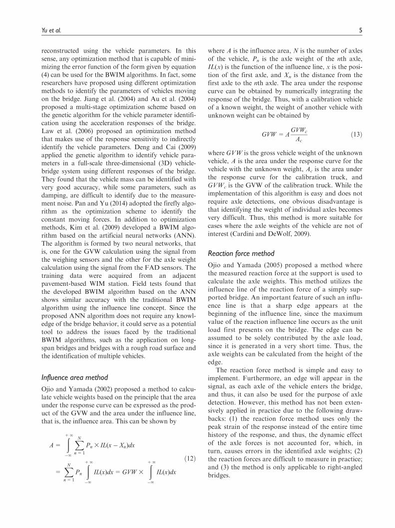
Influence area method
Ojio and Yamada (2002) proposed a method to calcu-late vehicle weights based on the principle that the areaunder the response curve can be expressed as the prod-uct of the GVW and the area under the influence line,that is, the influence area. This can be shown by
A=
ð+‘
�‘
XN
n= 1
Pn 3 IL(x� Xn)dx
=XN
n= 1
Pn
ð+‘
�‘
IL(x)dx=GVW 3
ð+‘
�‘
IL(x)dx
ð12Þ
where A is the influence area, N is the number of axlesof the vehicle, Pn is the axle weight of the nth axle,IL(x) is the function of the influence line, x is the posi-tion of the first axle, and Xn is the distance from thefirst axle to the nth axle. The area under the responsecurve can be obtained by numerically integrating theresponse of the bridge. Thus, with a calibration vehicleof a known weight, the weight of another vehicle withunknown weight can be obtained by
GVW =AGVWc
Ac
ð13Þ
where GVW is the gross vehicle weight of the unknownvehicle, A is the area under the response curve for thevehicle with the unknown weight, Ac is the area underthe response curve for the calibration truck, andGVWc is the GVW of the calibration truck. While theimplementation of this algorithm is easy and does notrequire axle detections, one obvious disadvantage isthat identifying the weight of individual axles becomesvery difficult. Thus, this method is more suitable forcases where the axle weights of the vehicle are not ofinterest (Cardini and DeWolf, 2009).
Reaction force method
Ojio and Yamada (2005) proposed a method wherethe measured reaction force at the support is used tocalculate the axle weights. This method utilizes theinfluence line of the reaction force of a simply sup-ported bridge. An important feature of such an influ-ence line is that a sharp edge appears at thebeginning of the influence line, since the maximumvalue of the reaction influence line occurs as the unitload first presents on the bridge. The edge can beassumed to be solely contributed by the axle load,since it is generated in a very short time. Thus, theaxle weights can be calculated from the height of theedge.
The reaction force method is simple and easy toimplement. Furthermore, an edge will appear in thesignal, as each axle of the vehicle enters the bridge,and thus, it can also be used for the purpose of axledetection. However, this method has not been exten-sively applied in practice due to the following draw-backs: (1) the reaction force method uses only thepeak strain of the response instead of the entire timehistory of the response, and thus, the dynamic effectof the axle forces is not accounted for, which, inturn, causes errors in the identified axle weights; (2)the reaction forces are difficult to measure in practice;and (3) the method is only applicable to right-angledbridges.
Yu et al. 5

Moving Force Identification
The MFI method seeks to obtain the complete timehistory of the vehicle axle forces when a vehicle passesthe bridge. The MFI method has the potential to bevery accurate in the identification of static axle weights,since the complete history of the time-varying forceswill allow the dynamic effects of the vehicle to be iden-tified and removed when calculating the static axleweights. The MFI theory has been developed since the1990s when several classic MFI methods were pro-posed including the interpretive method (IM), the timedomain method (TDM), and the frequency–timedomain method (FTDM).
Interpretive Methods. O’Connor and Chan (1988) pro-posed an IM in which the beam is modeled as anassembly of lumped masses interconnected by masslesselastic beam elements. The identification process istreated as an inverse problem to the predictive analysisfor the beam in which the dynamic responses of thebeam are derived as
fYg= ½YA�fPg � ½YI �½Dm�f€Yg � ½YI �½C�f _Yg ð14Þ
fMg= ½MA�fPg � ½MI �½Dm�f€Yg � ½MI �½C�f _Yg ð15Þ
where fYg, f _Yg, f€Yg, and fMg are the vectors for thenodal displacements, velocities, accelerations, andbending moments, respectively; fPg is the vector ofaxle loads; ½Dm� is the diagonal matrix of lumped mass;½C� is the damping matrix; ½YA� and ½MA� are thematrices in which the ith column representing thenodal displacements and bending moments caused bya unit load acting at the position of the ith axle load,respectively; ½YI � and ½MI � are the nodal displacementmatrix and the bending moment matrix, respectively,with their ith column representing the correspondingresponse, that is, displacement or bending moment,caused by a unit load acting at the ith node. It can beseen from equations (14) and (15) that once fYg orfMg is known at any instant, f _Yg and f€Yg or f _Mgand f €Mg can be obtained using a numerical differen-tiation method. Then, equation (14) or equation (15)becomes an over-determined set of linear simultaneousequation, where fPg can be solved using the least-squares method. For the purpose of discussion, thismethod is referred to as the interpretive method I(IMI).
Chan et al. (1999) proposed another IM which usesthe Euler’s beam theory instead of the beam-elementmodel. The equation of motion of the Euler–Bernoullibeam can be written as
r∂2v(x, t)
∂t2+C
∂v(x, t)
∂t+EI
∂4v(x, t)
∂x4= d(x� ct)P(t) ð16Þ
where r is the mass per unit length, v(x, t) is the deflec-tion of the beam at position x and time t, C is thedamping coefficient, E is the Young’s modulus, I is themoment of inertia of the cross section, d(x� ct) is theDirac delta function, and P(t) is the axle force movingat a constant speed of c. Using the modal superposi-tion technique, the solution of equation (16) can beexpressed as
v(x, t)=X‘
n= 1
sinnpx
Lqn(t) ð17Þ
where qn(t) is the modal displacement for the nth mode.Substituting equation (17) into equation (16) gives
€qn(t)+ 2jnvn _qn(t)+vn2qn(t)
=2P(t)
rLsin
np�x
L(n= 1, 2, . . . ,‘)
ð18Þ
where vn is the natural frequency for the nth mode, jn
is the damping ratio for the nth mode, and �x is the dis-tance between the moving force and the left end of thebeam, assuming that the force P is moving from the leftto the right. If there are k moving forces, equation (18)can be written in matrix form as
€q1
€q2
..
.
€qn
8>>>><>>>>:
9>>>>=>>>>;
+
2j1v1 _q1
2j2v2 _q2
..
.
2jnvn _qn
8>>>><>>>>:
9>>>>=>>>>;
+
v12q1
v22q2
..
.
vn2qn
8>>>><>>>>:
9>>>>=>>>>;
=2
rL
sinp(ct � x1)
Lsin
p(ct � x2)
L� � � sin
p(ct � xk)
L
sin2p(ct � x1)
Lsin
2p(ct � x2)
L� � � sin
2p(ct � xk)
L
..
. ... ..
. ...
sinnp(ct � x1)
Lsin
np(ct � x2)
L� � � sin
np(ct � xk)
L
26666666664
37777777775
P1
P2
..
.
Pk
8>>>><>>>>:
9>>>>=>>>>;
ð19Þ
where xk is the distance between the kth axle load andthe first axle load.
To obtain the time history of the axle forces, themeasured response is first transferred to the modal dis-placement. Then, the numerical differentiation methodis used to obtain the modal velocity and accelerationfrom the modal displacement. Therefore, equation (19)again becomes an over-determined set of linear equa-tions where the axle load Pk can be solved using theleast-squares method. For the purpose of discussion,this method is referred to as the interpretive method II(IMII).
Time Domain Method. Law et al. (1997) developed a sys-tem identification method based on the modal super-position principle. In their method, the dynamic
6 Advances in Structural Engineering

deflection can be obtained by solving equation (16) inthe time domain using the convolution integral
v(x, t)=X‘
n= 1
2
rLv9nsin
npct
L
ðt
0
e�jnvn(t�t) sin v9n(t � t) sinnpct
LP(t)dt
ð20Þ
where v9n is the damped natural frequency and is equal
to vn
ffiffiffiffiffiffiffiffiffiffiffiffiffiffiffi1� jn
2p
. Since the axle force P(t) and the deflec-tion v(x, t) can be treated as step functions in a smalltime interval, equation (20) can be written in discreteterms and rearranged into a set of linear equationsfrom which P(t) can be solved using the least-squaresmethod in the time domain.
Frequency-time Domain Method. Law and Chan (1999)proposed the FTDM, where equation (16) is solved inthe frequency domain to identify the axle forces. TheFourier transformation of the deflection v(x, t) can beexpressed as
V (x,v)=X‘
n= 1
2
rLsin
npx
LHn(v)P(v) ð21Þ
Hn(v)=1
vn2 � v2 + i2jvnv
ð22Þ
Pn(v)=1
2p
ð‘
�‘
pn(t)e�ivtdt ð23Þ
pn(t)=P(t) sinnpct
Lð24Þ
where Hn(v) is the frequency response function of thenth mode, and Pn(v) is the Fourier transformation ofthe modal force pn(t).
Similarly, the real and imaginary parts of P(v) canbe obtained by solving a set of simultaneous equationsin the frequency domain. Then, the time history of theaxle force P(t) can be found by performing the inverseFourier transformation.
It can be seen that for the above MFI methods, theproblem eventually becomes solving the linear alge-braic equation of the form
Ax= b ð25Þ
where A is an m-by-n matrix. In the case of MFI prob-lems, m is larger than n and the over-determined set ofsystem equations can be solved using the least-squaresmethod leading to
x=A+b= ½(AT A)�1AT �b ð26Þ
where A+ denotes the pseudo-inverse (PI) of thematrix A, and x is called the PI solution. In order to beable to obtain this PI solution, A needs to have a fullrank. However, it was found that sometimes thereexists linear dependency in A, which would increase theerror of the PI solution (O’Connor and Chan, 1988).To overcome this problem, the singular value decom-position (SVD) technique can be used to calculate A+.In fact, it has been shown by some studies that usingthe SVD can significantly improve the accuracy of theidentified force history, especially for the FTDM (Yuand Chan, 2002, 2003, 2007). However, it was stillfound that the identified results are sensitive to noiseand exhibit large fluctuations, since the nature of theinverse problem is ill-conditioned. In this case, regulari-zation is necessary to provide bounds to the solution.Many researchers adopted the Tikhonov regularizationmethod and found that the regularization is very effec-tive in reducing the effect of noise on the identificationaccuracy (Deng and Cai, 2010; Law et al., 2004; Lawand Fang, 2001; Law and Zhu, 2000; Zhu and Law,2000, 2002a). Nevertheless, this method requires find-ing the optimal regularization parameter using meth-ods such as cross-validation (Golub et al., 1979) andthe L-curve method (Hansen, 1992), which is usuallytime-consuming. To resolve this issue, Pinkaew (2006)proposed a regularization method using the updatedstatic component (USC) technique and found that theidentification accuracy using the USC technique is notsensitive to the regularization parameter, and that theidentification using the USC technique actually pro-vides a better accuracy than the conventional regulari-zation method (Asnachinda et al., 2008; Pinkaew,2006; Pinkaew and Asnachinda, 2007).
Following the development of the classic MFI the-ories, some comparative studies have been conductedto investigate the effectiveness of the four methodsunder different conditions and the sensitivity of eachmethod to the errors in the vehicle-bridge parametersand the measurement parameters (Chan et al., 2000b,2001a, 2001b; Yu and Chan, 2007; Zhu and Law,2002b). Furthermore, much effort has also been madeto improve the accuracy and to extend the applicabilityof existing MFI algorithms. Zhu and Law (1999)extended the IMII to a continuous bridge which ismodeled as a multi-span Timoshenko beam. Chanet al. (2000a) and Chan and Yung (2000) applied theTDM and the IMI in the MFI on pre-stressed concretebridges considering the pre-stressing effect in the beammodel. Zhu and Law (2000) extended the TDM to abridge deck that is modeled as an orthotropic plateand introduced the Tikhonov regularization to providebounds to the identified force. Zhu and Law (2001)used the exact solution of the mode shapes consideringthe rigid support condition for the IMII, which
Yu et al. 7

eliminates the modeling errors from the assumed modeshapes. Also, they adopted the generalized orthogonalfunction to obtain the derivatives of the bridge modalresponse so as to reduce the errors due to the measure-ment noise. Zhu and Law (2003) revised the way thatthe system matrices are calculated in the TDM, whichimproved the computational efficiency of the method.Zhu and Law (2006) applied the TDM on a multi-spanbridge deck that is modeled as an Euler–Bernoullibeam with elastic restraints at the supports. Chan andAshebo (2006) proposed identifying moving forces oncontinuous bridges using the TDM by considering theresponse of only one of the spans. Asnachinda et al.(2008) presented a method to identify multiple vehicleson a continuous bridge based on the FE method,where the bridge is modeled as a continuous Euler–Bernoulli beam. Dowling et al. (2012) adopted thecross-entropy optimization method to infer the mate-rial properties required to form the mass and stiffnessmatrices and thus solved the issue of FE model cali-bration for the MFI algorithm.
Meanwhile, some novel MFI algorithms have beenproposed. Law and Fang (2001) developed a newmethod for the MFI based on the state-space formula-tion and dynamic programming, which inherently pro-vides bounds to the ill-conditioned force. Law et al.(2004) presented an MFI method based on the FEmethod and the improved system condensation tech-nique. The error caused by the modal truncation isthus eliminated by expressing the measured displace-ments as shape functions. Law et al. (2008) introduceda new MFI method based on the wavelet decomposi-tion and FE method. This method requires no assump-tion on the initial condition of the system. Deng andCai (2010, 2011) proposed a new identification methodbased on the superposition principle and influence sur-face and adopted a 3D FE model for the bridge usedin their studies. Wu and Law (2010) presented a sto-chastic identification algorithm that can deal withcomplex random excitation forces with large uncer-tainties and system parameters with small uncertain-ties. The algorithm is formed based on the establishedstatistical relationship between the random excitationforces and the structural responses which are assumedto be Gaussian and are represented by the Karhunen–Loeve expansion.
Despite the fact that the MFI methods have thepotential to be very accurate and ideal for directenforcement, there are still many challenges to imple-ment the MFI algorithms in the modern commercialBWIM systems. First, the MFI is computationallyexpensive and thus, it may be difficult to achieve thereal-time identification of axle weights. Furthermore,most of the previous studies on the MFI are still basedon overly simplified bridge models such as simple
beams and plates. However, in practice, 3D bridgemodels must be adopted in order to accurately reflectthe behavior of the bridge. The Moses’ algorithm, onthe other hand, is simple to implement. As long as cer-tain requirements are met, the accuracy of the Moses’algorithm can satisfy the requirements for directenforcement, which makes the Moses’ algorithm theoptimal choice for modern commercial BWIM sys-tems. Other static algorithms have distinctive limita-tions and are, thus, not suitable for direct enforcement,but they can provide alternatives when the Moses’algorithm is not suitable.
Instrumentation of BWIM systems
An on-site BWIM system usually consists of a dataacquisition system, a communication system, a powersupply system, and sensors. For example, Figure 1shows the components of the SiWIM system, a com-mercially available BWIM system that was originallydeveloped within the framework of the WAVE project(2001) and has been continuously improved andupdated over the years. The data collected from theon-site system are processed with software usingBWIM algorithms. The results are then presented in agraphical user interface (GUI) that is designed forusers to visualize the real-time monitoring data. Thefollowing sections will introduce the typical instrumen-tation of BWIM systems including the types of sensorsused in a BWIM system and their installationlocations.
Strain measurement
In a modern BWIM system, the sensors can be dividedinto two main categories, that is, the weighing sensorsand the axle-detecting sensors. Weighing sensors usu-ally measure the global bending strain of the bridgedue to the vehicle loading which serves as the maininput for the calculation of axle weights, that is, themeasured strain in a certain girder ei in equation (1). Itshould be noted that although the MFI methods allowthe displacement and the acceleration responses to beused for axle load identifications as shown in someprevious studies (Deng and Cai, 2011; Yu and Chan,2003; Zhu and Law, 2000), they are challenging toimplement, and responses such as displacements aredifficult to measure in practice. Therefore, strainresponses are the best available information for mod-ern commercial BWIM systems, and the selection ofan appropriate type of sensors for strain measurementsbecomes important to ensure the accuracy of the mea-surement and reliable operation of the system.Common types of sensors used for strain measure-ments include foil strain gauges, vibrating wire strain
8 Advances in Structural Engineering

gauges, and fiber Bragg grating (FBG) sensors. In thissection, the applicability of these sensors for BWIMsystems will be discussed.
Foil strain gauges. Foil strain gauges have been com-monly used for strain measurements. When the mea-sured material is strained, the foil will deform andcause the electrical resistance to change. This change iscalibrated to reflect the equivalent change in strain.Foil strain gauges can be attached to the surface of thestructural components. They are cheap and haveacceptable accuracy, which makes them suitable forexperimental tests and short-term measurements.However, they are not suitable for long-term fieldmeasurements as in the case of BWIM systems due totheir poor durability and susceptibility to electromag-netic interferences and environmental changes.
Vibrating wire strain gauges. Vibrating wire strain gaugescan either be embedded in concrete or mounted on thesurface of structural components. It works based onthe principle that the change in strain will cause achange of the tension in the wire, which leads to thevariation in the resonant frequency of the wire.Vibrating wire strain gauges have good durability, andtheir installation requires little surface preparation.However, the vibrating wire strain gauge has a low
scanning rate, which makes it difficult to record thedynamic response of the bridge when the vehicle tra-vels at a high speed.
Fiber optic sensors. Fiber optic sensors, especially FBGsensors, have become increasingly popular in the fieldof structural health monitoring (SHM). FBG sensorsuse the relationship between the change of the wave-length in the reflected spectrum and the strain inducedby forces or temperature changes to measure the strain.FBG sensors have the following advantages when com-pared to conventional strain gauges: (1) FBG sensorsare immune to electromagnetic interferences, whicheliminates the noise from external sources to a certaindegree; (2) FBG sensors have good durability, whichmakes them suitable for long-term measurements; and(3) FBG sensors have small sizes and can be multi-plexed, which allows easy installation of multiple sen-sors on large structures. These advantages have madeFBG sensors an excellent candidate for BWIM appli-cations. Recent studies have also found that usingFBG-based sensors improved the accuracy of theBWIM system overall (Lydon et al., 2014, 2015).
Axle detection
In a modern BWIM system, axle-detecting sensors areused to identify the presence of vehicle axles from
Figure 1. Components of an SiWIM system: (1) FAD sensors, (2) spider, (3) weighing sensors, (4) cabinet and panel, (5) batteries,(6) solar panels, (7) solar panel installation, (8) antenna, (9) camera, (10) PDA.From Zhao et al. (2014) with permission from ASCE.
Yu et al. 9

which the speed and axle spacing of the vehicle can becalculated. Axle detection is an indispensable part ofthe BWIM system, since the identified vehicle speedand axle spacing of the vehicle will directly affect theresults of the axle weight calculation. The traditionalinstruments for axle detection include tape switchesand pneumatic tubes. Moses (1979) pointed out thattape switches are easier to be incorporated into the sys-tem, while the pneumatic tubes require a pressure-sensing device to produce the signal of axle passage.The identification of vehicle speed and axle spacingusing traditional axle detectors is actually quite simple.Usually, two parallel axle detectors are placed on theroad surface, where the spacing between the two detec-tors is measured as an input into the system. In somecases, where the transverse location of the vehicle needsto be determined, a third detector is placed diagonallywith a known angle corresponding to the other twodetectors. Nevertheless, the installation of axle detec-tors on the pavement usually requires lane closure, andthe poor durability of sensors also diminishes theadvantage of the BWIM systems over the pavement-based WIM systems.
To overcome the problems of the traditional axledetection, the FAD algorithm was first proposed in theWAVE project (2001). The basic idea of the FAD algo-rithm is to use FAD sensors to replace traditional axledetectors on the road surface. The FAD sensors mea-sure the local strain responses, and thus, they pick up asharp peak upon each axle passage above the sensorlocation. Typically, two FAD sensors are installed atdifferent longitudinal locations on each lane with aknown distance. Figure 2 shows some typical signals ofthe FAD sensors, which were recorded when a five-axletruck passed through the bridge (Zhao et al., 2014). Itcan be seen that each FAD sensor picked up five peakscorresponding to the five axles. However, it should bementioned that clear peaks in the strain signal might
not occur if the wheel load is directly applied over thebeam (Lydon et al., 2015). In practice, a correlationfunction is usually used to calculate the vehicle speed.The correlation function is defined as
Corr(t)=
ð+‘
�‘
f (t)g(t+ t)dt ð27Þ
where f(t) and g(t) are the signals of the FAD sensorsat two longitudinal locations, respectively. To calculatethe vehicle speed, the time taken by the vehicle to passthe known distance between the two sensors is needed.From equation (27), it can be seen that the correlationfunction will reach the maximum value when f(t) andg(t + t) both reach the maxima, that is, picking up thepeak corresponding to the same vehicle axle. Since thetime difference between f(t) and g(t + t) is t, the timedifference t0 that gives the maximum value of the cor-relation function is the time taken by the same vehicleaxle to pass the known distance between the two FADsensors, and then the vehicle speed can be easily calcu-lated using the known distance and the time differencet0. Once the vehicle speed is known, the axle spacingcan be obtained using the time difference between thepeaks in the FAD signals (Kalin et al., 2006).
Although the FAD algorithm resolves the durabil-ity problem of the traditional axle detectors, it stillrequires additional sensors, that is, the FAD sensors,only for the purpose of axle detection. Furthermore,the FAD algorithm imposes certain restrictions uponthe span length and superstructure thickness of theselected bridge. Namely, the FAD algorithm is notapplicable to all types of bridges. As a general rule ofthumb, the bridges suitable for the FAD algorithmshould have the following: (1) a short span or rela-tively longer span but with transverse supports, that is,secondary members such as transverse cross-beams orstiffeners, to divide the bridge into sub-spans, becauselonger spans will have joint contributions of severalaxles that make it difficult to distinguish individualaxles; (2) a thin superstructure, because a thick super-structure will ‘‘smear’’ the peaks induced by the vehicleaxles; and (3) a smooth road surface and approachspan, since a rough surface condition will cause signifi-cant dynamic effects which impose additional peaksinto the signal (Kalin et al., 2006; WAVE, 2001). Thetypes of bridges that have already been identified assuitable for the FAD algorithm include orthotropicdeck bridges, short integral bridges with thin slabs(usually 6–12-m long with the slab thickness between40 and 60 cm), and beam-slab bridges with secondarymembers (WAVE, 2001).
Recently, the concept of a nothing-on-road (NOR)BWIM system was proposed. The goal of the NOR
Figure 2. Typical FAD signals of a five-axle truck crossing.From Zhao et al. (2014) with permission from ASCE.
10 Advances in Structural Engineering

BWIM system is to free the use of axle detectors onthe road surface. While the FAD algorithm is oneapplication of the NOR BWIM, a more effective wayis to directly employ the global strain signal obtainedfrom the weighing sensors to identify the vehicle speedand axle spacing. This will be a very attractive featurefor future commercial BWIM systems, since it reducesthe number of sensors required and thus the cost of thesystem, making the installation even easier. Besides, itdoes not impose any restriction on the selection ofbridges, which helps extend the application of BWIMtechnologies. However, direct identification from theglobal strain signal is very difficult, since it usuallydoes not have a sharp peak upon each axle passage.Nevertheless, it has been shown by some researchersthat the identification can be achieved through propersignal-processing techniques such as a wavelet-basedanalysis, which are suitable to treat non-stationary sig-nals. Dunne et al. (2005) first proposed using wavelettransformation to identify closely spaced axles fromthe FAD signals. Chatterjee et al. (2006) conductedfield testing on a culvert and adopted the wavelettransformation to analyze the strain signal obtainedfrom vehicle crossing. The results show that the wave-let techniques can help identify closely spaced axleswithin a tandem or tridem group which could not bedirectly identified from the FAD signal and reveal thepotential of using the wavelet techniques to identifyvehicle axles from the strain signal of weighing sensors.Yu et al. (2015) proposed a vehicle axle identificationmethod based on the wavelet transformation of theglobal signal. The numerical results showed that thismethod could provide accurate identification of vehicleaxles using only the weighing sensors.
In addition, some other methods for axle detectionshave also been reported. Some researchers found thatcrack openings on the bottom of the concrete slabs aresensitive to axle loads, and thus, they measured thechanges in the widths of existing cracks to detect thevehicle axles (Lechner et al., 2010; Matui and El-Hakim, 1989). However, this method cannot be gener-alized, since it is only applicable to bridges with crackopenings. Wall et al. (2009) adopted an approachwhere the change of slope induced by the axle passageis used for the axle identification. In an ideal setting,the passage of each axle will have a correspondingimpulse in the second derivative of the strain signal.However, in practice, this approach requires the strainsignal to have evident slope discontinuities; in otherwords, the strain signal must show a certain level ofsensitivity to the vehicle axles. Also, as these slope dis-continuities are only subtle changes, this approachmay no longer be feasible once the measurement noiseis introduced in practice. O’Brien et al. (2012) pro-posed a novel axle detection strategy using shear strain
sensors based on the assumption that each axle pas-sage will induce a sudden change of the shear strain.Preliminary FE analyses were carried out on a beam-slab bridge, and the interface of the web and the flangewas recommended for the sensor locations. Furtherwork was planned in order to assess the feasibility ofthis novel axle detection method. In addition, with therecent advances in the image-processing technologies,the identification of the vehicle axle configuration hasbeen made possible through proper image analysisalgorithms, and thus, a vision-based system utilizing aroadside camera was proposed by some researchers asa potential tool for the axle detection (Caprani et al.,2013; Ojio et al., 2016).
Installation location of sensors
The sensor installation locations should account forseveral factors including the function of sensors, typesof bridges, strain levels, sensitivity-to-strain variations,and so on. In this section, the sensor installation loca-tions will be discussed with respect to the two mostimportant factors, that is, the function of sensors andtypes of bridges chosen for installation. In addition, acase study with specific sensor layouts on a typicalbeam-slab bridge is also presented.
Function of sensors. Weighing sensors measure the glo-bal bending strain caused by vehicle loads, and thus,they are usually installed at locations of the most pro-nounced responses, for example, the mid-span of thebridge. Nevertheless, it is interesting to note that otherinstallation locations have also been reported forweighing sensors. For example, in the reaction forcemethod proposed by Ojio and Yamada (2005), theweighing sensors were attached to the end vertical stif-feners above the supports of a steel plate girder bridgeto measure the strain for the bearing. For complexbridge structures, the locations of weighing sensors canbe determined by a preliminary FE analysis. As foraxle-detecting sensors, both the traditional axle detec-tion and the FAD algorithm require two parallel linesof sensors to be installed at a known distance.However, the differences are the following: (1) the tra-ditional axle-detecting sensors are installed on the roadsurface, while the FAD sensors are installed under-neath the bridge; (2) the traditional axle-detecting sen-sors can be installed at almost any location on thebridge; however, the selection of the installation loca-tions for the FAD sensors depends on the shape of theinfluence line, since the influence line at the location ofinstallation needs to present a sharp peak in order forthe axle identification.
Yu et al. 11

Types of bridges. The sensitivity of strain responses toaxle loads differs between different bridge types anddifferent measurement locations on a certain bridge;thus, the specific plan of sensor layouts for each bridgeshould be determined on a case-by-case basis.Nevertheless, based on the existing BWIM practices,the general schemes of sensor layouts for some typicalbridges are summarized and shown in Table 1. Itshould be mentioned that the reason for requiring onlyone line of axle-detecting sensors in orthotropic deckbridges is that the installed weighing sensors can alsopick up sharp peaks corresponding to the axle passage,namely, the weighing sensors in this case also serve thepurpose of axle detection.
In addition, Brown (2011) studied the influence ofdifferent installation schemes of FAD sensors on theaccuracy of axle detections, including the longitudinaland transverse locations, and installation angles. Basedon the signals obtained from a T-beam-reinforced con-crete bridge, it was concluded that FAD sensors shouldbe orientated longitudinally and installed close to thebeginning or the end of the bridge span, ideally directlybelow the wheel path, in order to obtain a clear signalwith sharp peaks. The reason for choosing the begin-ning or the end of the bridge span is that the bridge isstiffer at these locations, and thus, more definite peakscan be produced. The dynamic effects at these stifferlocations are also less pronounced, which leads to acleaner signal. Furthermore, the study also shows thatcompared to longitudinally orientated sensors, trans-versely orientated sensors provide poor signals for axledetection. Besides, it was also found that weighing sen-sors do not have to be installed exactly at the mid-span,since any location near the mid-span can provide anadequate strain level for weighing purposes.
Case study. In order to give a better illustration on thesensor installation of the BWIM system, a case studyis presented here. The case study is chosen from arecent BWIM practice conducted by Zhao et al. (2014)in Alabama. The instrumented bridge is a three-span
simply supported concrete multi-girder bridge. Thethree spans have an equal length of 12.8 m, and thefirst span was chosen for the installation of the BWIMsystem. The reasons for selecting this bridge are as fol-lows: (1) the bridge has a short span and thin super-structure, suggesting that it is suitable for theimplementation of the FAD algorithm; (2) the shortspan has higher natural frequencies to avoid matchingthe natural and pseudo frequencies of the vehicle andthus reduces the dynamic effect of the moving vehicles;and (3) the bridge has a smooth approach and a goodsurface condition, which again helps minimize thedynamic effect.
For the sensor installations, a total of four weighingsensors were installed in a parallel manner underneaththe girders (one for each girder), and a total of fourFAD sensors were mounted beneath the concrete slab(two for each lane). The specific sensor layouts are pre-sented in Figure 3. It should be noted that the sensorsare not installed exactly at the mid-span because of thediaphragm.
Data acquisition and storage
In a BWIM system, the collection of raw data from thesensors is achieved through an on-site data acquisitionsystem. The sensors communicate with the data acqui-sition system by wired or wireless connections. Thecore of a data acquisition system is a well-designedalgorithm of data sampling and recording. Based onthe Nyquist–Shannon sampling theorem, it is sug-gested that the sampling frequency for the data collec-tion be at least twice the maximum vibration frequencyof interest so as to prevent the folding and aliasingproblems when digitizing the data (Paultre et al.,1995). In practice, the sampling frequency may behigher and an anti-aliasing filter may be necessary aswell. However, the sampling frequency should not betoo high as this will result in a huge volume of databeing stored. Nevertheless, in terms of long-term moni-toring, the amount of produced data will still be
Table 1. General layout schemes of BWIM sensors for typical types of bridges.
Types of bridges Location of weighing sensors Location of axle-detecting sensors
Longitudinal Transverse Longitudinal Transverse
Orthotropic deck bridges Mid-span Bottom of thelongitudinal stiffener
One line of sensors at asection away from themid-span
Bottom of the longitudinal stiffener
Integral slab bridges Bottom of the slab Two lines of sensors attwo sections away fromthe mid-span
Bottom of the slabBeam-slab bridges Bottom of the girder Bottom of the slab
BWIM: bridge weigh-in-motion.
12 Advances in Structural Engineering

enormous. This problem can be resolved by establish-ing an event-triggering mechanism, that is, the straindata will only be recorded and stored when a criticalevent, which is defined as a truck with a certain weightthat is larger than the minimum weight of interestpasses through the bridge. This can be done by settinga lower limit for the sensor, and the value of the lowerlimit is determined by the maximum response causedby the load corresponding to the minimum truckweight. In this case, only those critical events underwhich the bridge responses equal or exceed the lowerlimit will be recorded, and thus, the amount of storeddata will be significantly reduced.
Conclusion and remarks
This article presents a comprehensive review on thestate-of-the-art BWIM technologies from two
important perspectives, that is, the BWIM algorithmsand instrumentation of BWIM systems. On the basisof recent developments achieved in the field, the fol-lowing conclusions can be drawn and remarks can bemade:
1. The BWIM technique has significant advan-tages over the pavement-based WIM technique.BWIM systems are more durable, and theirinstallations are also easier and safer.Moreover, BWIM systems are potentially moreaccurate than pavement-based WIM systems.
2. The static BWIM algorithms include theMoses’ algorithm, the influence area method,the reaction force method, and the orthotropicBWIM algorithm. Although the accuracy ofthe Moses’ algorithm depends on several fac-tors, it is straightforward and relatively simple
Figure 3. Sensor layouts of a typical BWIM system (cm).From Zhao et al. (2014) with permission from ASCE.
Yu et al. 13

to implement. The influence area method canbe used to estimate the GVW; however, it is dif-ficult to identify the weight of individual axles.The reaction force method is simple to imple-ment; however, some drawbacks have limitedits extensive applications. The orthotropicBWIM algorithm employs a different optimiza-tion scheme and can serve as an alternative tothe Moses’ algorithm in some cases.
3. The MFI methods, that is, the dynamic BWIMalgorithms, have the potential to be very accu-rate. However, they also have distinctive draw-backs when compared to the static BWIMalgorithms, including expensive computationand requiring detailed FE model of the bridge.Besides, most of the current MFI theories arestill based on simple bridge models. These dis-advantages have made it difficult to implementthe MFI algorithms in modern commercialBWIM systems.
4. In a modern BWIM system, weighing sensorsare used to measure the global strain responsesof the bridge. Of all the candidates for weighingsensors, FBG sensors are considered the mostsuitable for the BWIM application, since FBGsensors have many advantages over the tradi-tional strain gauges such as the ease of installa-tion, capability of multiplexing, gooddurability, and electromagnetic immunity.
5. The traditional axle detectors have been gradu-ally replaced by the FAD sensors in the mod-ern BWIM systems. The FAD algorithmutilizes the sharp peaks in the local strainresponses measured by FAD sensors to identifythe axle presence. Nevertheless, a more effectiveapproach to achieve the NOR BWIM is toidentify vehicle axles from the signals of weigh-ing sensors through the use of well-chosen sig-nal-processing techniques. The implementationof such an axle identification scheme wouldfurther simplify the installation and reduce thecost of BWIM systems.
Through the review of the recent developments ofBWIM technologies, the following issues are identified,and corresponding suggestions for the future researchare tentatively proposed:
1. The application of BWIM techniques on longbridges has rarely been studied. This is becauseof the following: (1) the possibility of multiple-vehicle presence, which is difficult to identify,increases in long bridges; (2) longer bridgeshave lower natural frequencies that are morelikely to match the vehicle frequencies and thus
increase the dynamic effect; (3) the speed of thevehicle is more likely to change during thecrossing on long bridges; and (4) it is easier toidentify closely spaced axles in shorter bridges(WAVE, 2001). To overcome these difficultiesand achieve the implementation of BWIM sys-tems on long bridges, future research may referto unconventional methods such as a neuralnetwork as possible alternatives to the tradi-tional BWIM algorithms whose accuracies aresusceptible to the occurrence of multiple-vehiclepresence and significant dynamic effects causedby either a rough road surface or the frequencymatching between the vehicle and bridge.
2. Even though the MFI methods have the poten-tial to be very accurate, it is still not fully readyto be implemented in the modern commercialBWIM systems. This is because of the follow-ing: (1) the MFI algorithms are computation-ally demanding, which makes it difficult toachieve the real-time identification of vehicleparameters; (2) the MFI algorithms require anaccurate FE model of the bridge that is usuallydifficult to obtain; and (3) most of the proposedMFI algorithms are still based on simple mod-els that may not be able to accurately representthe real behavior of bridges. Nevertheless, theMFI is still considered to be a very promisingalgorithm for future commercial BWIM sys-tems. Thus, future research should focus onemploying optimization and condensationmethods to reduce the calculation efforts andextending the current MFI theories to 3Dbridge models.
3. Although the current practice of the FAD algo-rithm has been proven to be successful on cer-tain types of bridges, it still requires additionalFAD sensors to identify the vehicle axles, andthe algorithm also imposes restrictions on theselection of bridges, which limit its applica-tions. Naturally, a more advanced method ofachieving the NOR BWIM is to identify allvehicle parameters from the weighing sensors.This will be considered as a very attractive fea-ture in the future development of commercialBWIM systems. Nevertheless, current studieson this topic are still limited and are based onsimple bridge models. More research should beconducted to explore the effectiveness of identi-fying vehicle speed and axle spacing from thestrain signals of weighing sensors and to extendthe identification algorithm to more complexbridge structures.
4. The information extracted from BWIM systemscan also be used for the purpose of SHM or
14 Advances in Structural Engineering

vice versa. There have been some recent investi-gations on the use of BWIM systems for dam-age detection (Cantero et al., 2015; Canteroand Gonzalez, 2015; Carey et al., 2013; Zhuand Law, 2015) and determination of dynamicamplification factors (O’Brien et al., 2013;Zhao and Uddin, 2014). In the future, moreresearch can be focused on incorporatingBWIM technologies into the SHM systems tofurther extend their applications and reduce thecost of SHM systems.
Declaration of Conflicting Interests
The author(s) declared no potential conflicts of interest withrespect to the research, authorship, and/or publication of thisarticle.
Funding
The author(s) disclosed receipt of the following financial sup-port for the research, authorship, and/or publication of thisarticle: The study was financially supported by the key basicresearch project (973 projects) of P.R. China, under contractno. 2015CB057701 and by the Louisiana Transportation andResearch Center (no. 13-2ST). The contents presented reflectonly the views of the authors.
References
Asnachinda P, Pinkaew T and Laman J (2008) Multiple vehi-
cle axle load identification from continuous bridge bend-ing moment response. Engineering Structures 30(10):
2800–2817.Au F, Jiang R and Cheung Y (2004) Parameter identification
of vehicles moving on continuous bridges. Journal of
Sound and Vibration 269(1–2): 91–111.Biezma MV and Schanack F (2007) Collapse of steel bridges.
Journal of Performance of Constructed Facilities 21(5):398–405.
Brown AJ (2011) Bridge weigh-in-motion deployment opportu-
nities in Alabama. Master Thesis, Department of Civil,
Environmental and Construction Engineering, University
of Alabama, Tuscaloosa, AL.Cantero D and Gonzalez A (2015) Bridge damage detection
using weigh-in-motion technology. Journal of Bridge Engi-neering 20(5): 04014078.
Cantero D, Karoumi R and Gonzalez A (2015) The VirtualAxle concept for detection of localised damage using
Bridge Weigh-in-Motion data. Engineering Structures
89(15): 26–36.Caprani C, O’Brien EJ and Blacoe S (2013) Vision systems
for analysis of congested traffic assessment. In: Proceed-
ings of the IABSE conference, Rotterdam, 6–8 May, pp.1–8. Zurich: IABSE.
Cardini AJ and DeWolf JT (2009) Implementation of a long-
term bridge weigh-in-motion system for a steel girder
bridge in the interstate highway system. Journal of Bridge
Engineering 14(6): 418–423.
Carey CH, O’Brien EJ and Keenahan J (2013) Investigating
the use of moving force identification theory in bridge
damage detection. Key Engineering Materials 569–570:
215–222.Chan TH and Ashebo DB (2006) Theoretical study of mov-
ing force identification on continuous bridges. Journal of
Sound and Vibration 295(3–5): 870–883.Chan TH and Yung TH (2000) A theoretical study of force
identification using prestressed concrete bridges. Engineer-
ing Structures 22(11): 1529–1537.Chan TH, Law SS and Yung TH (2000a) Moving force iden-
tification using an existing prestressed concrete bridge.
Engineering Structures 22(10): 1261–1270.Chan TH, Law SS, Yung TH, et al. (1999) An interpretive
method for moving force identification. Journal of Sound
and Vibration 219(3): 503–524.Chan TH, Yu L and Law SS (2000b) Comparative studies on
moving force identification from bridge strains in labora-
tory. Journal of Sound and Vibration 235(1): 87–104.
Chan TH, Yu L, Law SS, et al. (2001a) Moving force identi-
fication studies, I: theory. Journal of Sound and Vibration
247(1): 59–76.Chan TH, Yu L, Law SS, et al. (2001b) Moving force identi-
fication studies, II: comparative studies. Journal of Sound
and Vibration 247(1): 77–95.Chatterjee P, O’Brien EJ, Li Y, et al. (2006) Wavelet domain
analysis for identification of vehicle axles from bridge mea-
surements. Computers & Structures 84(28): 1792–1801.COST 323 (2002) Weigh-in-motion of road vehicles. Final
report of the COST 323 Action (WIM-LOAD), Labora-
toire Central des Ponts et Chaussees, Paris.Dempsey AT, Jacob B and Carracilli J (1999) Orthotropic
bridge WIM for determining axle and gross vehicle
weights. In: O’Brien EJ and Jacob B (eds) Proceedings of
the final symposium of the project WAVE. Paris: Hermes
Science Publications, pp. 227–238.
Deng L and Cai CS (2009) Identification of parameters of
vehicles moving on bridges. Engineering Structures 31(10):
2474–2485.Deng L and Cai CS (2010) Identification of dynamic vehicu-
lar axle loads: theory and simulations. Journal of Vibra-
tion and Control 16(14): 2167–2194.Deng L and Cai CS (2011) Identification of dynamic vehicu-
lar axle loads: demonstration by a field study. Journal of
Vibration and Control 17(2): 183–195.Dowling J, O’Brien EJ and Gonzalez A (2012) Adaptation
of Cross Entropy optimisation to a dynamic Bridge WIM
calibration problem. Engineering Structures 44: 13–22.Dunne D, O’Brien EJ, Basu B, et al. (2005) Bridge WIM sys-
tems with nothing on the road (NOR). In: Proceedings of
the 4th international WIM conference, Taipei, Taiwan, 20–
23 February, pp. 109–117. Zurich: International Society
for Weigh-in-Motion.Fu G and Hag-Elsafi O (2000) Vehicular overloads: load
model, bridge safety, and permit checking. Journal of
Bridge Engineering 5(1): 49–57.Golub GH, Heath M and Wahba G (1979) Generalized
cross-validation as a method for choosing a good ridge
parameter. Technometrics 21(2): 215–223.
Yu et al. 15

Hansen PC (1992) Analysis of discrete ill-posed problems by
means of the L-curve. SIAM Review 34(4): 561–580.Ieng S (2015) Bridge influence line estimation for bridge
weigh-in-motion system. Journal of Computing in Civil
Engineering 29(1): 06014006.Jacob B and Beaumelle VFL (2010) Improving truck safety:
potential of weigh-in-motion technology. IATSS Research
34(1): 9–15.Jiang R, Au F and Cheung Y (2004) Identification of vehicles
moving on continuous bridges with rough surface. Journal
of Sound and Vibration 274(3–5): 1045–1063.Kalin J, Znidaric A and Lavric I (2006) Practical implemen-
tation of nothing-on-the-road bridge weigh-in-motion sys-
tem. Slovenian National Building and Civil Engineering
Institute 207: 3–10.Kim S, Lee S, Park M, et al. (2009) Vehicle signal analysis
using artificial neural networks for a bridge weigh-in-
motion system. Sensors 9(10): 7943–7956.Law SS and Chan TH (1999) Moving force identification—a
frequency and time domains analysis. Journal of Dynamic
Systems, Measurement and Control 121(3): 394–401.Law SS and Fang Y (2001) Moving force identification: opti-
mal state estimation approach. Journal of Sound and
Vibration 239(2): 233–254.Law SS and Zhu XQ (2000) Study on different beam models
in moving force identification. Journal of Sound and
Vibration 234(4): 661–679.Law SS, Bu JQ, Zhu XQ, et al. (2004) Vehicle axle loads
identification using finite element method. Engineering
Structures 26(8): 1143–1153.Law SS, Bu JQ, Zhu XQ, et al. (2006) Vehicle condition
surveillance on continuous bridges based on response
sensitivity. Journal of Engineering Mechanics 132(1): 78–86.Law SS, Chan TH and Zeng QH (1997) Moving force identi-
fication: a time domain method. Journal of Sound and
Vibration 201(1): 1–22.Law SS, Wu SQ and Shi ZY (2008) Moving load and pres-
tress identification using wavelet-based method. Journal
of Applied Mechanics 75(2): 021014 (7 pp.).Lechner B, Lieschnegg M, Mariani O, et al. (2010) A
wavelet-based bridge weigh-in-motion system. Interna-
tional Journal on Smart Sensing and Intelligent Systems
3(4): 573–591.Lydon M, Taylor S, Robinson D, et al. (2014) Development
of a bridge weigh-in-motion sensor: performance compar-
ison using fiber optic and electric resistance strain sensor
systems. IEEE Sensors Journal 14(12): 4284–4296.Lydon M, Taylor S, Robinson D, et al. (2015) Recent devel-
opments in bridge weigh in motion (B-WIM). Journal of
Civil Structural Health Monitoring 6(1): 69–81.McNulty P and O’Brien EJ (2003) Testing of bridge weigh-
in-motion system in sub-Arctic climate. Journal of Testing
and Evaluation 31(6): 1–10.Matui S and El-Hakim A (1989) Estimation of axle loads of
vehicle by crack opening of RC slab. Journal of Structural
Engineering: ASCE 35A: 407–418 (in Japanese).Moses F (1979) Weigh-in-motion system using instrumented
bridges. Transportation Engineering Journal of ASCE
105(3): 233–249.
O’Brien EJ, Gonzalez A, Dowling J, et al. (2013) Direct mea-
surement of dynamics in road bridges using a bridge
weigh-in-motion system. The Baltic Journal of Road and
Bridge Engineering 8(4): 263–270.O’Brien EJ, Hajializadeh D, Uddin N, et al. (2012) Strategies
for axle detection in bridge weigh-in-motion systems. In:
Proceedings of the 6th international WIM conference, Dal-
las, TX, 4–7 June, pp. 79–88. Hoboken, NJ: Wiley.O’Brien EJ, Quilligan M and Karoumi R (2006) Calculating
an influence line from direct measurements. Proceedings
of the ICE: Bridge Engineering 159(1): 31–34.O’Brien EJ, Rowley CW, Gonzalez A, et al. (2009) A regu-
larised solution to the bridge weigh-in-motion equations.
International Journal of Heavy Vehicle Systems 16(3):
310–327.O’Brien EJ, Znidaric A and Dempsey AT (1999) Comparison
of two independently developed bridge weigh-in-motion
systems. International Journal of Heavy Vehicle Systems
6(1–4): 147–161.O’Connor C and Chan TH (1988) Dynamic wheel loads from
bridge strains. Journal of Structural Engineering: ASCE
114(8): 1703–1723.
Ojio T and Yamada K (2002) Bridge weigh-in-motion sys-
tems using stringers of plate girder bridges. In: Proceed-
ings of the 3rd international WIM conference, Orlando,
FL, 13–15 May, pp. 209–218. Ames, IA: Iowa State
University.Ojio T and Yamada K (2005) Bridge WIM by reaction force
method. In: Proceedings of the 4th international WIM con-
ference, Taipei, Taiwan, 20–23 February, pp. 97–108. Zur-
ich: International Society for Weigh-in-Motion.Ojio T, Carey C, O’Brien EJ, et al. (2016) Contactless bridge
weigh-in-motion. Journal of Bridge Engineering. Epub
ahead of print 8 February. DOI: 10.1061/
(ASCE)BE.1943-5592.0000776.Pan C and Yu L (2014) Moving force identification based on
firefly algorithm. Advanced Materials Research 919(1):
329–333.Paultre P, Proulx J and Talbot M (1995) Dynamic testing
procedures for highway bridges using traffic loads. Jour-
nal of Structural Engineering: ASCE 121(2): 362–376.Peters RJ (1984) AXWAY—a system to obtain vehicle axle
weighings. In: Proceedings of the 12th Australian road
research board conference, Hobart, TAS, Australia, 27–31
August, vol. 12, issue 2, pp. 10–18. Vermont South, VIC,
Australia: ARRB Group Limited.Peters RJ (1986) CULWAY—an unmanned and undetect-
able highway speed vehicle weighing system. In: Proceed-
ings of the 13th Australian road research board conference,
Adelaide, SA, Australia, 25–29 August, vol. 13, issue 6,
pp. 70–83. Vermont South, VIC, Australia: ARRB Group
Limited.Pinkaew T (2006) Identification of vehicle axle loads from
bridge responses using updated static component tech-
nique. Engineering Structures 28(11): 1599–1608.Pinkaew T and Asnachinda P (2007) Experimental study on
the identification of dynamic axle loads of moving vehicles
from the bending moments of bridges. Engineering Struc-
tures 29(9): 2282–2293.
16 Advances in Structural Engineering

Quilligan M (2003) Bridge Weigh-in-Motion: developmentof a 2-D multi-vehicle algorithm. Trita-BKN: Bulletin 69:A–144.
Richardson J, Jones S, Brown A, et al. (2014) On the use ofbridge weigh-in-motion for overweight truck enforce-ment. International Journal of Heavy Vehicle Systems
21(2): 83–104.Rowley C, Gonzalez A, O’Brien EJ, et al. (2008) Comparison
of conventional and regularized bridge weigh-in-motionalgorithms. In: Proceedings of the international conference
on heavy vehicles, Paris, 19–22 May, pp. 221–230. Hobo-ken, NJ: Wiley.
Tikhonov AN and Arsenin VY (1977) Solutions of Ill-PosedProblems. New York: Winston.
Wall CJ, Christenson RE, McDonnell AH, et al. (2009) Anon-intrusive bridge weigh-in-motion system for a single
span steel girder bridge using only strain measurements.Report no. CT-2251-3-09-5, August. Newington, CT:Connecticut Department of Transportation.
Wardhana K and Hadipriono FC (2003) Analysis of recentbridge failures in the United States. Journal of Perfor-
mance of Constructed Facilities 17(3): 144–150.WAVE (2001, June) Weighing-in-motion of axles and vehicles
for Europe (WAVE). Report of work package 1.2. Paris:Laboratoire Central des Ponts et Chaussees.
Wu S and Law SS (2010) Moving force identification basedon stochastic finite element model. Engineering Structures
32(4): 1016–1027.
Xiao Z, Yamada K, Inoue J, et al. (2006) Measurement oftruck axle weight by instrumenting longitudinal ribs oforthotropic bridge. Journal of Bridge Engineering 11(5):526–532.
Yamaguchi E, Kawamura S, Matuso K, et al. (2009) Bridge-Weigh-in-Motion by two-span continuous bridge withskew and heavy-truck flow in Fukuoka area, Japan.Advances in Structural Engineering 12(1): 115–125.
Yu L and Chan TH (2002) Moving force identification frombending moment responses of bridge. Structural Engineer-ing and Mechanics 14(2): 151–170.
Yu L and Chan TH (2003) Moving force identification basedon the frequency–time domain method. Journal of Soundand Vibration 261(2): 329–349.
Yu L and Chan TH (2007) Recent research on identificationof moving loads on bridges. Journal of Sound and Vibra-
tion 305(1–2): 3–21.Yu Y, Cai CS and Deng L (2015) Vehicle axle identification
using wavelet analysis of bridge global responses. Journalof Vibration and Control. Epub ahead of print 27 Decem-ber. DOI: 10.1177/1077546315623147.
Zhao H, Uddin N, O’Brien EJ, et al. (2014) Identification of
vehicular axle weights with a bridge weigh-in-motion sys-
tem considering transverse distribution of wheel loads.
Journal of Bridge Engineering 19(3): 04013008.Zhao H, Uddin N, Shao X, et al. (2015) Field-calibrated
influence lines for improved axle weight identification
with a bridge weigh-in-motion system. Structure and Infra-
structure Engineering: Maintenance, Management, Life-
Cycle Design and Performance 11(6): 721–743.Zhao Z and Uddin N (2014) Determination of dynamic
amplification factors using site-specific B-WIM data.
Journal of Bridge Engineering 19(1): 72–82.Zhu XQ and Law SS (1999) Moving forces identification on
multi-span continuous bridge. Journal of Sound and Vibra-
tion 228(2): 377–396.Zhu XQ and Law SS (2000) Identification of vehicle axle
loads from bridge dynamic responses. Journal of Sound
and Vibration 236(4): 705–724.Zhu XQ and Law SS (2001) Orthogonal function in moving
loads identification on a multispan bridge. Journal of
Sound and Vibration 245(2): 329–345.Zhu XQ and Law SS (2002a) Moving loads identification
through regularization. Journal of Engineering Mechanics
128(9): 989–1000.Zhu XQ and Law SS (2002b) Practical aspects in moving
load identification. Journal of Sound and Vibration 258(1):
123–146.Zhu XQ and Law SS (2003) Identification of moving interac-
tion forces with incomplete velocity information. Mechan-
ical Systems and Signal Processing 17(6): 1349–1366.Zhu XQ and Law SS (2006) Moving load identification on
multi-span continuous bridges with elastic bearings.
Mechanical Systems and Signal Processing 20(7):
1759–1782.Zhu XQ and Law SS (2015) Structural health monitoring
based on vehicle-bridge interaction: accomplishments and
challenges. Advances in Structural Engineering 18(12):
1999–2005.Znidaric A and Baumgartner W (1998) Bridge weigh-in-
motion systems – an overview. In: Proceedings of the 2nd
European conference on weigh-in-motion of road vehicles,
Lisbon, 14–16 September, pp. 139–151. Luxembourg:
Office for Official Publications of the European
Communities.Znidaric A, Lavric I, Kalin J, et al. (2012) Using strips to
mitigate the multiple-presence problem of BWIM systems.
In: Proceedings of the 6th international WIM conference,
Dallas, TX, 4–7 June, pp. 89–98. Hoboken, NJ: Wiley.
Yu et al. 17