advances in materials research: an internship at · pdf fileadvances in materials research: an...
TRANSCRIPT
"
NASA USRP - Internship Final Report
Advances in Materials Research: An Internship at KennedySpace Center
Elizabeth A. Barrios'Wayne State University, Detroit, Michigan, 48202, USA
Luke B. Roberson2
NASA Engineering, Kennedy Space Center, FL, 32899, USA
My time at Kennedy Space Center. was spent immersing myself in research performed in theMaterials Science Division of the Engineering Directorate. My Chemical Engineeringbackground provided me the ability to assist in many different projects ranging from tensiletesting of composite materials to making tape via an extrusion process. However, I spent themajority of my time on the following three projects: (1) testing three different materials todetermine antimicrobial properties; (2) fabricating and analyzing hydrogen sensing tapesthat were placed at the launch pad for STS-133 launch; and (3) researching molten regolithelectrolysis at KSC to prepare me for my summer internship at MSFC on a closely relatedtopic. This paper aims to explain, in detail, what I have learned about these three mainprojects. It will explain why this research is happening and what we are currently doing toresolve the issues. This paper will also explain how the hard work and experiences that Ihave gained as an intern have provided me with the next big step towards my career atNASA.
NomenclatureAODCCDCHPCKSCLN2
MOEMSFCNASAO2
PDMSPdOPSIGR2ARTVSRBSTEMSTSTi02
TSM
Acridine Orange Direct CountsCenter for Disease ControlHeterotrophic Plate CountsKennedy Space CenterLiquid NitrogenMolten Oxide ElectrolysisMarshall Space Flight CenterNational Aeronautics and Space AdministrationOxygen gasPolydimethylsiloxanePalladium (II) oxidePounds per square inch (gauge)R2 AgarRoom Temperature VulcanizationSolid Rocket BoosterScience, Technology, Engineering, and MathematicsSpace Transportation SystemTitanium dioxideTail Service Mast
I NASA Student Research Intern, NASA Engineering, Kennedy Space Center, Wayne State University.2 Polymer Chemist, NASA Engineering, NE-L6, Kennedy Space Center.
Kennedy Space Center Spring 2011 Session
https://ntrs.nasa.gov/search.jsp?R=20110014450 2018-05-13T18:28:27+00:00Z
NASA USRP - Internship Final Report
PrologueRocket Scientist. Space Shuttle. Astronomer. The Moon. The Universe. Monkeys. Those are a few thoughts that
pass through children's brain when the word "NASA" is presented to them. Sure NASA consists of a lot more thanthose few topics, but as a child, they do not know much more than what they learn in a history or science class. Atthe elementary and middle school level, an interest develops in the sciences and a select few students will continuetheir life pursuing a career in a STEM related field. However, a majority of these students will move onto highschool and eventually college to realize that the STEM field requires a lot more work than other fields. This detersmany students away from pursuing their interests in science. It is my goal to inspire students to pursue their dreams,much like I am doing now, and that hard work, persistence, and determination pays off in the long run.
I realized all of this about children in recent education outreach events that I participated in. One of the mostnotable outreach events I did happened prior to the beginning of my internship at KSC. Before leaving for Florida, Iwent and spoke to a group of gtll graders about how I am living my dreams and working towards my ultimate goal ofone day permanently working for NASA. I spoke to them about NASA in general, how I got interested in NASA,and how I work every day to make sure my dreams become a reality. At the beginning of my presentation, I hadmultiple questions asking various things ranging from if I have any friends, if I have anytime to play sports, etc.They assumed that because r am studying chemical engineering that I only study, nothing else. The term"engineering" intimidates a lot of people, so r reassured them that even though I spend a great deal of time duringschool studying and applying myself towards my goals, I do in fact have friends and that I have a social life outsideof school. I explained to them my involvement with a sorority, my regular workout schedule, my volunteeringactivities, and my general hanging out with my friends. They were all very surprised that I did all of this. I evenheard from multiple students that although they like their science classes a lot, they would never want to do itforever because it takes up too much time and they wouldn't have a life. I think after telling my story, I changed alot of their minds because after this revelation, I was bombarded with questions regarding science and NASA. r wasasked things like "How do the shuttles lift off?", "What is chemical engineering?", "What does NASA do?", "Howdo I become an astronaut?", "How do 1 become the owner of NASA?", and my personal favorite, "Can r send amonkey into space?" All of these questions showed me that I somehow had inspired these kids enough to make themthink about science and NASA, even if it was just for that day. However, I know that I made a bigger impact than Ihad expected. I have kept the principal of that school up-to-date with all my wonderful adventures as a KSC intern,including pictures and postcards. She has been showing them to her students and has told me that they can't wait forme to come back and tell them about what I have done. This is one of the most rewarding experiences I have hadthus far in my life, and it has definitely gave me an extra edge to continue pushing harder than ever to pursue mylifelong dream of working for NASA.
My time as a KSC intern this past spring has provided me with the next big step in my pursuit of having a job atNASA when I graduate college. It has allowed me to receive an internship position at Marshall Space Flight Centerthrough the NASA Academy program. This summer at MSFC r will be expanding my knowledge on In-SituResource Utilization by designing a prototype system that will perform molten oxide electrolysis using ionic liquids.
2Kennedy Space Center Spring 20 II Session
NASA USRP - Internship Final Report
Chapter 1: Antimicrobial Materials in Water Treatment Systems
I. IntroductionThis project was performed under a Non-Disclosure Agreement and Space Act Agreement KCA-4240, so all
materials have been given alternative labels to meet Sensitive But Unclassified (SBU) requirements.
The human body is composed of a very high percentage of water; approximately 70 % depending on the person.Therefore, it is makes sense that water is a very crucial element in any manned spaceflight mission. The astronautsonboard the spacecraft utilize water in a wide variety of ways ranging from rehydrating food and beverages forconsumption to plain drinking water to personal hygiene tasks. On a daily basis, one crew member will use over 5kg of potable water (6.6 pounds) for rehydration efforts and drinking water alone. An even greater amount of waterwill be used when personal hygiene tasks are added into the equation. In order to provide a sufficient supply ofwater to the astronauts, NASA has set the following water supply standards6 for manned spaceflight:
Potable Water (for consumption): 5.68 - 8.0kg water/ person-dayPersonal Hygiene: 37.03 kg water/ person-day
These numbers verify how impractical it would be to try and re-supply the spacecraft with the total amount ofwater for the duration of a mission. The water would begin to add a great deal of weight to the spacecraft and wouldoccupy too much room. Therefore, for any type of manned spaceflight mission (long or short duration), water mustbe able to be recycled and made potable from within a closed-loop system. When water is recycled, there is anincreased potential for the growth of pathogenic and opportunistic organisms, which could compromise theastronaut's health. Currently, microbial growth is controlled by using chemical biocides, either iodine or ionic silver,in order to decontaminate the water6
. Although both materials have provided sufficient microbial control, they havetheir disadvantages. These chemicals have low human toxicity thresholds and require multiple doses (a re-supply) toremain effective as their antimicrobial potency decreases over time. It is for these reasons that NASA has beguninvestigations into new antimicrobial methods.
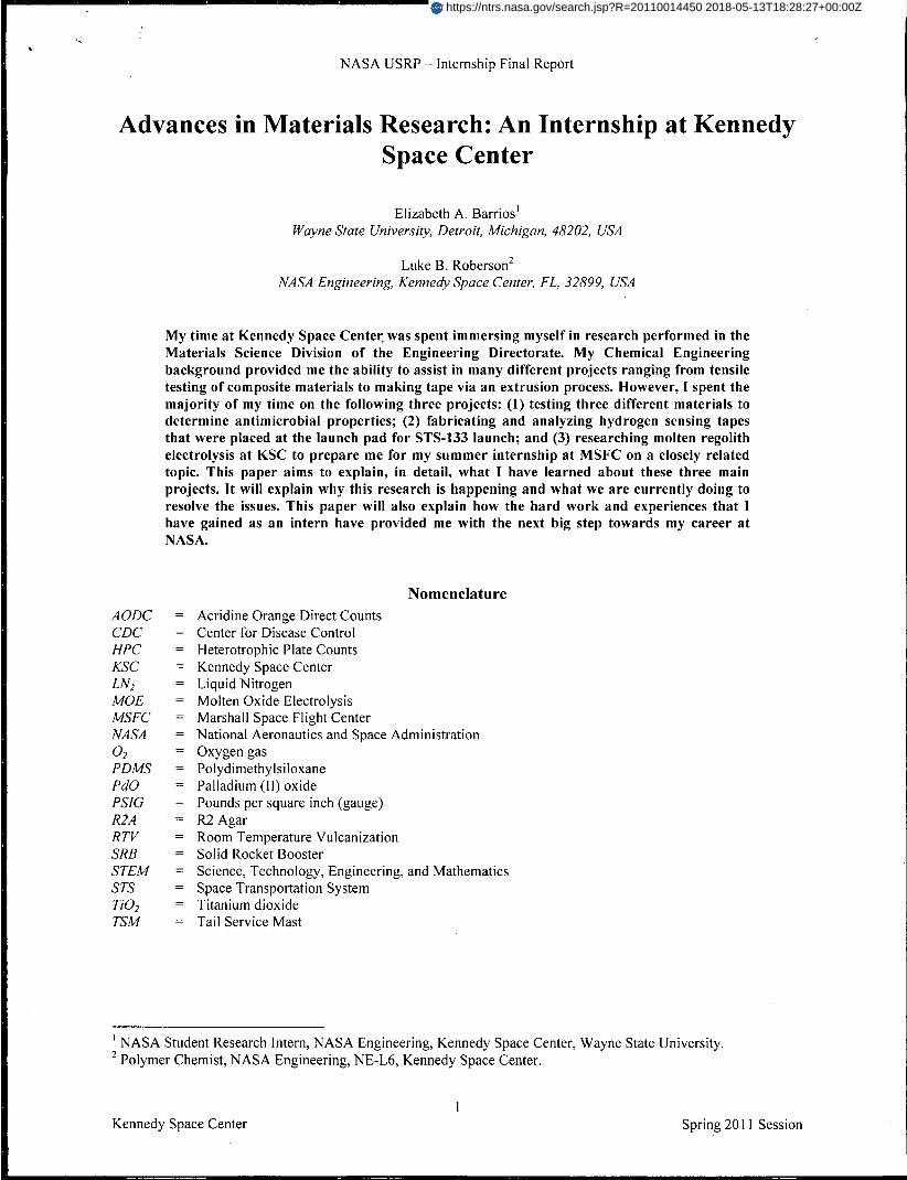
At Kennedy Space Center, one method of proposed microbial control involves applying an antimicrobialmaterial coating to the interior surface of a water system. In order to investigate this newly proposed method,experimentation on the log reduction of the microbe, Pseudomonas aeruginosa (strain ERC 1) was performed usingthe Center for Disease Control (CDC) High Shear Bioreactor.
Three different antimicrobial materials (Antimicrobial A, B, and C) were used in conjunction with two differentpolymer coupons, polydimethylsiloxane (PDMS) and acrylic, in order to perform the necessary tests. All of thecoupons used during experimentation were uniform in size with a 12 mm diameter. The polymers were used forimprinting ofa surface topography to mimic the microbe-resistant properties found in nature.
Figure 1. CDCBiofilm Reactor
Materials and MethodsIn order to test the three different antimicrobial materials, ASTM E 2562-07
Method "Standard Test Method for Quantification of Pseudomonas aeruginosaBiofilm Grown with High Shear and Continuous Flow using CDC BiofilmReactor" was followed.
The CDC reactor can hold eight rods, each rod containing spots for threeremovable coupons for sampling purposes providing a maximum of 24 samplingpoints for each trial. Figure 1 shows an illustration of the CDC Biofilm Reactor l
.
To prepare for each trial, the reactor was sterilized using ethylene trioxide (ETO)a minimum of 10 days prior to the start date of the trial. This 10 day time periodwas necessary for the reactor to release any trapped gas that may haveaccumulated. Using an environmental control chamber, the reactor wasmaintained at a temperature of 21 ± 2°C, a relative humidity of 50%, 400 ppm ofCO2, and no light during all trials.
All coupons used during each trial were uniform round, 12 mm diameter disks.Each trial period consisted of 18 samples: 3 smooth coupons with noantimicrobial, 3 patterned coupons with no antimicrobial, 6 smooth coupons withthe antimicrobial, and 6 patterned coupons with the antimicrobial.
The microbe used during all trials was Pseudomonas aeruginosa, strain ERC]. Pseudomonas aeruginosa wasplated onto aseptic R2A plates using the streak plating method (Fig. 2). This method grows individual colonies to be
II.
3Kennedy Space Center Spring 20 II Session

NASA USRP - Internship Final Report
Mot'''I.., Po.nm. ~OOJ
Figure 3. Reactor set-up
Figure 2. Streak PlatingMethod
used to prepare the microbe for placement into the reactor. To prepare the microbe for the reactor, 50 rnL of 900mg/L TSB was added to three different flasks. One of the three flasks remained blank (no addition of the microbe) inorder to verify there was no contamination in the TSB media. One colony of Pseudomonas aeruginosa was added toeach of the two remaining flasks. The three flasks were then incubated in a stirring incubator for 24 hours at 37°C.
After 24 hours, the optical density of the microbe solution is taken at 590 nm. Fortesting purposes, a microbe concentration of 1 x 10⁸ cells/mL was desired. Theresulting concentration immediately after removal from the incubator is generallyhigher that what is desired. A conversion takes place to obtain the desiredconcentration by using the following formula:
Where C, is the initial concentration found by determining the optical density, VIis the unknown volume of microbe, C2 is the desired concentration, and V2 is thedesired volume needed for the reactor.
To prepare the reactor for each trial, 300 mg/L of TSB wass poured directlyinto the reactor. Then, 1 mL of the 1x10⁸ cells/mL concentration of Pseudomonasaeruginosa was inserted into the reactor by using a feed tube. Following this
insertion, the feed tube is rinsed with 1mL of sterile water, resulting in a fmal concentration of Pseudomonasaeruginosa inside the reactor of 2xlOscells/rnL. The reactor was then placed on a stir plate at 130 rpm for 24 hours.This was the batch phase of the trial. During the batch phase, there is no flow through the reactor. The only shearthat is present comes from the stir plate. These are the optimal biofilm growth conditions. Following this 24 hourtime period, the reactor began to operate in its continuous flow phase where the carbon source (1 OOmg/L TSB)flowed into the reactor via a peristaltic pump at 11.7 mUmin.The entire set up for the reactor can be seen in Fig. 3 1
•
Harvesting of the coupon samples was done followingthis full 48-hour test period. The material samples wereremoved from the coupons using a small pair of forceps andrinsed with 10 rnL of sterilized water (5 mL on each side ofmaterial sample). Each sample was then placed in a tubecontaining 3 mL of PBS (pH of 7.4). The biofilm wassuspended in solution by vortexing the sample tubes andsonicating them.
Quantifying the amount of viable cells after the reactorended was completed by using two methods: HeterotrophicPlate Counts (HPC) on R2A and Acridine Orange DirectCount (AODC). A serial dilution, carried out to a -5 dilution,took place prior to beginning the HPC procedures. Eachdilution was a 1: 100 ratio. 100 ilL of the -2, -3, and -4dilutions were plated onto aseptic R2A plates using the spread plating method. These plates were then placed in anincubator at 37°C and grown for 24 hours. After the 24 hour period, plates were removed from the incubator andvisually examined to determine which plate would produce a count with three signjficant figures. That plate withthree significant figures was then selected and counted. The AODC was performed by dying I mL of the vortexedand sonicated sample with 100 ilL of AO for 5 minutes. The dyed sample was then filtered through a blackMillipore filter and dried. The dried sample filter was then placed onto a drop of oil that was present on a test slide.Another drop of oil was added on top of the dried sample filter and was covered with a cover slip. These sampleswere then observed using the Zeiss Epi-Fluorescent Axioskop Microscope. The images from the sample slides weresaved using a DP Controller and DP Manager2
. The count for viable cells was completed by using the Image-ProExpress 7.0 software. The sample counts obtained from this software had an approximate error of 5% associatedwith it. The AODC process does not discriminate between viable and non-viable cells, and the Image-Pro softwarecannot count individual cells that may be clumped together.
III. Discussion of ResultsThe inoculum levels from each reactor trial were quantified using both HPC and AODC. The numbers obtained
from these methods verified that the reactors remained consistent between trials, producing sound results.
4Kennedy Space Center Spring 201 1 Session
NASA USRP - Internship Final Report
In order to be considered a good antimicrobial material, a minimum 5 loglo reduction between the samplecompared to the smooth control sample. From the data described below, none of the antimicrobial materials testedfor this paper produced a large enough log reduction to be considered a material with good antimicrobial potential.
Of the three antimicrobial materials, Antimicrobial A is the material which shows the least promise. WhenAntimicrobial A was patterned, a 0.06 10glO reduction was observed when compared with the smooth controlsample. When Antimicrobial A was not patterned, a reduction of 0.05 10glO was seen. When the sample waspatterned but did not contain Antimicrobial A, only a reduction of 0.04 10glO was seen.
When comparing the numerical results obtained from the trials performed on Antimicrobials Band C, thesematerials looked as though they were almost identical in efficacies. Antimicrobial B and Antimicrobial C that had apattern showed a 0.12 loglO and 0.39 loglo reduction, respectively. Antimicrobial B without a pattern showed a 0.2310glO reduction and Antimicrobial C without a pattern showed a 0.28 10giO reduction. Finally, a patterned samplewithout the antimicrobial showed a 0.21 log\o reduction for Antimicrobial B and a 0.04 10glO reduction forAntimicrobial C. Future modifications could be made on Antimicrobial B to improve its antimicrobial propertiesbecause it is a newer material being investigated. Antimicrobial C, being an older material, does not show as muchpromise.
Chapter 2: Hydrogen Tape
I. IntroductionHydrogen gas, a primary propellant for the launch of a space shuttle, is a colorless, odorless gas that has a lower
explosion limit of approximately 4% in air6• A hydrogen leak is an incredibly dangerous scenario putting Shuttle
personal at risk and potentially causing a launch delay until the problem is found and fixed. The most recentexample of a delay due to the detection of a hydrogen leak was the attempted launch of Space Shuttle Discovery inNovember 2010. The detection of this leak was one of a few problems that caused Discovery's launch to bepostponed to February 2011.
In order to assist in locating the exact site of a hydrogen leak and to better maintain the launch schedule, a colorchanging tape was developed. The idea was to use an irreversible chemochromic hydrogen sensing pigment thatwould change from beige to gray in an ideal situation. This pigment would then be incorporated into a siliconematrix that would be made into a thin tape to be applied at various flanges along the hydrogen lines that fuel theSpace Shuttles. The pigment that was used in this study was prepared by plating palladium (II) oxide (PdO) ontotitanium dioxide (TiOz). The initial pigment is beige in color. When exposed to hydrogen gas, the palladium that ispresent reacted with the hydrogen gas and participated in a reduction reaction. Once the reduction reaction tookplace, the palladium was present in its metallic form where it is grey in color, causing a color change in the tape. Thereaction just described is depicted below5
:
PdO + Hz ~ Pd + H2 0
The hydrogen tape would be useless if it could not withstand the harsh effects of a launch. Before the tape couldbe deployed at the launch pad, it had to pass two different NASA/KSC standards, one for flammability (Test I ofNASA-STD-(l )-600 IA) and one for electrostatic discharge (KSC/MMA-1985-79). In addition to these two NASAstandards, the tape used for final deployment had to be able to withstand the cryogenic temperatures experienced onthe hydrogen lines during a launch as well as remain unaffected by UV radiation from the sun8
•
II. Previous FindingsIn recent years, multiple studies were conducted at KSC on the development of hydrogen sensing materials.
These studies led to crucial findings that guided researchers in their selection of materials and parameters. Some ofthe significant discoveries are described below.
Studies5 were conducted to determine how the Pd~ particle size plated on various types of Ti02 affected thechemochromic behaviors of the hydrogen sensing pigment. Based on a study of four different synthesized pigments,chemochromic activity was shown to be highly affected by the size of the Pd~ particles and how muchagglomeration on the surface was present. They concluded that small Pd~ particles with a hemispherical crystallinestructure produced a faster color change in the presence of hydrogen versus particles with a spherical structure. Theyalso concluded that the more agglomeration of particles at the surface, the larger the color change produced.
Another study that was completed8 investigated the influence that low operating temperatures had on thereaction rate of the hydrogen tape. This study was completed on a 3.6 mil thick Teflon tape composed with a 3 wt%of the hydrogen sensing pigment. Initial studies were done at -50°C but reacted too slowly. Therefore, triplicates
5Kennedy Space Center Spring 2011 Session
NASA USRP - Internship Final Report
were run at the temperature of room temperature, O°C, and 20°C. According to the data collected and graphsproduced, the average reaction rate was directly influenced by the operating temperature where a slower reactionrate was observed the lower the temperature.
In this same study, aerogel was added to the hydrogen sensing tapes to determine if it would aid in increasing thereaction rate at the lower operating temperatures. In order to complete this study, Cabot Corporation's NanogelAerogel 102 was incorporated into tape made of Versify 2300 (Dow Corning Chemical Corporation) with a 1.5 wt%of the hydrogen sensing pigment. The percentage of aerogel incorporated into the tapes included 0, 2.5, and 10 wtOlo.After exposing each tape to 100 % H2 at 2.4 psig and analyzing the data, it was found that the incorporation ofaerogel into the hydrogen tape increased the reaction rate at lower operational temperatures.
The final topic addressed in this same study tested the durability of flame resistant RTV. Initial laboratory testingof durability of flame resistant RTV was conducted on a tape fabricated with Dow Coming Silicone RTV SE 9189 LWhite with a 3 wt% of the hydrogen sensing pigment. By using a cable tie, the tape was placed on a piece of tubingcontaining running stream of LN2• The stream of LN2 ran for 30 minutes, exposing the tape to the cryogenictemperatures that would be experienced during a launch. After exposure to the LN2, the tape was removed andinspections showed that the cryogenic temperatures did not structurally damage this tape. A tape made of DowCorning RTV Sealant 739 was placed at the launch pad during the initial cryogenic loading for STS-133. This tapedid not withstand the extreme cryogenic temperatures and tore apart. After laboratory studies were completed, it wasdetermined that the cause for tearing was due to the added stresses of wrapping the tape too tightly around theflanges on the hydrogen lines. When this same laboratory testing was done on the tape composed of Dow ComingSilicone RTV SE 9189 L White, it was found that this material also tore if the tape was stretched too tightly whilebeing exposed to cryogenic temperatures. These findings were taken into consideration when placing the finalhydrogen tape at Launch Pad 39A for the launch of STS-133 on February 24,2011.
III. STS-133: DiscoveryFor the final launch of space shuttle Discovery (STS-133), a tape using
Dow Coming Silicone RTV SE 9189 L White was made with a 3%concentration of hydrogen sensing pigment. Four 100g batches were madeand were made to a thickness of35mils.
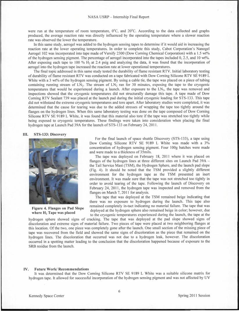
The tape was deployed on February 18, 20 II where it was placed onflanges of the hydrogen lines at three different sites on Launch Pad 39A the Tail Service Mast (TSM), the Hydrogen Sphere, and the launch pad slope(Fig. 4). It should be noted that the TSM provided a slightly differentenvironment for the hydrogen tape as the TSM presented an inertenvironment. It was made sure that the tape was not stretched too tightly inorder to avoid tearing of the tape. Following the launch of Discovery onFebruary 24, 2011, the hydrogen tape was inspected and removed from theflanges on March 7, 2011 for analysis.
The tape that was deployed at the TSM remained beige indicating thatthere was no exposure to hydrogen during the launch. This tape alsoremained completely in-tact indicating no material failure. The tape that was
Figure 4. Flanges on Pad Slopeh H Tid deployed at the hydrogen sphere also remained beige in color; however, due
were 2 ape was P ace to the cryogenic temperatures experienced during the launch, the tape at thehydrogen sphere showed signs of cracking. The tape that was deployed at the pad slope showed signs ofdiscoloration and extreme signs of material failure. Two pieces of tape were placed at two neighboring flanges atthis location. Of the two, one piece was completely gone after the launch. One small section of the missing piece oftape was recovered from the field and showed the same signs of discoloration as the piece that remained on thehydrogen lines. The discoloration that occurred was not due to a hydrogen leak, however. The discolorationoccurred in a spotting matter leading to the conclusion that the discoloration happened because of exposure to theSRB residue from the launch.
IV. Future Work! RecommendationsIt was determined that the Dow Coming Silicone RTV SE 9189 L White was a suitable silicone matrix for
hydrogen tape. It allowed for successful incorporation of the hydrogen sensing pigment and was not affected by UV
6Kennedy Space Center Spring 20 II Session
NASA USRP - Internship Final Report
radiation. It passed the flammability and electrostatic discharge tests. The onJy aspect where this tape failed was theability to withstand the cryogenic temperatures for long durations. It is suggested that future studies be conducted onincluding a fabric layer to the silicone matrix in order to better withstand these cryogenic temperatures and to resistcracking and tearing.
Chapter 3: In Situ Resource Utilization
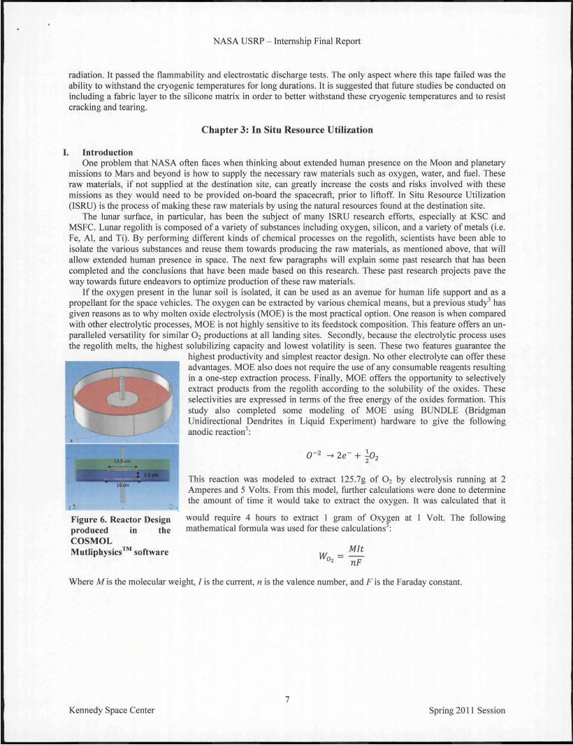
This reaction was modeled to extract 125.7g of O2 by electrolysis running at 2Amperes and 5 Volts. From this model, further calculations were done to determinethe amount of time it would take to extract the oxygen. It was calculated that it
would require 4 hours to extract ] gram of Oxygen at I Volt. The followingmathematical formula was used for these calculations3
:
MItWoz = nF
16 em
~,- .. ---
Figure 6. Reactor Designproduced in theCOSMOLMutliphysics™ software
I. IntroductionOne problem that NASA often faces when thinking about extended human presence on the Moon and planetary
missions to Mars and beyond is how to supply the necessary raw materials such as oxygen, water, and fuel. Theseraw materials, if not supplied at the destination site, can greatly increase the costs and risks involved with thesemissions as they would need to be provided on-board the spacecraft, prior to liftoff. In Situ Resource Utilization(ISRU) is the process of making these raw materials by using the natural resources found at the destination site.
The lunar surface, in particular, has been the subject of many ISRU research efforts, especially at KSC andMSFC. Lunar regolith is composed of a variety of substances including oxygen, silicon, and a variety of metals (i.e.Fe, AJ, and Ti). By performing different kinds of chemical processes on the regolith, scientists have been able toisolate the various substances and reuse them towards producing the raw materials, as mentioned above, that willallow extended human presence in space. The next few paragraphs will explain some past research that has beencompleted and the conclusions that have been made based on this research. These past research projects pave theway towards future endeavors to optimize production of these raw materials.
If the oxygen present in the lunar soil is isolated, it can be used as an avenue for human life support and as apropellant for the space vehicles. The oxygen can be extracted by various chemical means, but a previous study3 hasgiven reasons as to why molten oxide electrolysis (MOE) is the most practical option. One reason is when comparedwith other electrolytic processes, MOE is not highJy sensitive to its feedstock composition. This feature offers an unparalleled versatility for similar O2 productions at all landing sites. Secondly, because the electrolytic process usesthe regolith melts, the highest solubilizing capacity and lowest volatility is seen. These two features guarantee the
highest productivity and simplest reactor design. No other electrolyte can offer theseadvantages. MOE also does not require the use of any consumable reagents resultingin a one-step extraction process. Finally, MOE offers the opportunity to selectivelyextract products from the regolith according to the solubility of the oxides. Theseselectivities are expressed in terms of the free energy of the oxides formation. Thisstudy also completed some modeling of MOE using BUNDLE (BridgmanUnidirectional Dendrites in Liquid Experiment) hardware to give the followinganodic reaction3
:
Where M is the molecular weight, J is the current, n is the valence number, and F is the Faraday constant.
7Kennedy Space Center Spring 20] I Session

NASA USRP - Internship Final Report
R,goU'h I 1 S;><'OlIL I 1- I I___>\,1 S9!':'!Jl!!.l!i.!!.!J!'. f--_~.l (Ielln Il" M~t.d loos )pent IL, rf~t!1 Electrol~1 using
-, (It· of IL cOflwmed) I -I of P.rtlcubues ! of 'I Hydrogcn Gar. Uuct,od"
P,lrtlculOltes
I
Anode
Hydrosen
lonicllquld
H:O
0,
CuthodQ
A recent study published4 on oxygenextraction ITom lunar regolith using MOEcompleted a dimensional analysis on an MOEreactor design. The goal of this study was todesign a self-heating reactor that could produceenough Joule heat to create the molten productsand maintain that molten mixture throughout theMOE process. The Joule heat that would createand maintain the molten bath would be producedby the thermal energy created by passing an
electric current between the electrodes during the Figure 7. Preliminary Ionic Liquid Electrolysis Flow Chartelectrolysis process. A reactor of this design wouldgreatly reduce the external energy needed and would no longer be a necessary design component. Dominguez, J.A.,et.a!. produced the reactor design in Fig. 6 using the COSMOL Multiphysics™ modeling software4
• It wasconcluded that Joule heating was a sufficient method for producing heat to keep a molten mixture molten. However,when a model was made to simulate a "cold start" (where the material is not molten yet), Joule heating was not ableto provide enough heat to make the mixture molten. An external heating source would be needed to get the processstarted. Once started, Joule heating can then be utilized as a sufficient method to maintain enough heat to keep themixture molten.
Other studies have been conducted on extracting silicon from the lunar surface in order to fabricate solarphotovoltaic cells. It is suggested that the silicon from the lunar regolith can be used in conjunction with thevacuum-like atmosphere to initiate direct vapor deposition of the silicon onto thin film materials. These fabricatedsolar cells would then be used to provide energy "around the Earth/Moon system so every spacecraft we builddoesn't have to carry its own power source", as explained by previous NASA Administrator, Michael Griffin3
.
An in-depth discussion of the silicon extraction and solar cell fabrication advancement will not be explainedhere; however, research is still ongoing in these subject areas. For the purposes of this research paper, it is theoxygen extraction via molten oxide electrolysis that is of key interest.
II. Summer Research Project
Metals
Figure 8. PreliminaryChemical Flow of IonicLiquid Electrolysis
Advances in the world of ISRU research are always happening. One of themost recent advances was the development of a new method of extracting oxygenand metals from regolith of the Moon, Mars, and asteroids. At the MarshallSpace Flight Center's ISRU laboratory, methods are being developed to performmethods of electrolysis by using ionic liquid ~Iectrolytes. By using the ionicliquid electrolyte, the regolith would be able to be dissolved at temperatures lessthan 200°C, which is much lower than temperatures needed for MOE.
When performing electrolysis using ionic liquid electrolytes, the first stepoccurs in an extraction chamber where the product is water and the by-product isthe ionic liquid "ITame", meaning it no longer contains hydrogen. The water willthen be electrolyzed separating the oxygen and hydrogen. The current problemwith this method is that ITesh ionic liquids need to constantly be resupplied todissolve the regolith, as the spent ionic liquid no longer contains the neededhydrogen for this process to be carried out.
As a participant in the 20 II NASA Academy and a researcher under theguidance of Dr. Peter Curreri at Marshall's Space Flight Center, I will be workingtowards resolving this problem. During the months of June through August 20 II,I will be helping design a prototype laboratory system to extract space resources
using the methods of electrolysis with ionic liquids. The main design challenge will be to design a closed loopsystem that will be able to use the hydrogen extracted ITom the water to regenerate the spent ionic liquid. Theregenerated ionic liquid will then be recycled back to the extraction chamber so that more regolith may be dissolvedand the electrolysis process can continually be going. A preliminary process flow schematic of the recycling processflow diagram can be seen in Fig. 7 and a preliminary chemical flow schematic can be seen in Fig. 8.
8Kennedy Space Center Spring 20 II Session

NASA USRP - Internship Final Report
AcknowledgmentsI would first and foremost like to thank my mentor, Dr. Luke Roberson, for providing me with this amazing
internship opportunity. In the few professional experiences I have had as a college student, I have not had a mentorcare so much about his intern and their future. Luke has been so willing to make sure I get the most out of thisinternship opportunity. He has helped me discover where my true research interests lie and have helped me developas a young professional. He has taught me some many of the lessons on how succeed in this business world.
I would also like to give a special thanks to Megan Morford, Michele Birmele, and Dr. Mary Whitten who taughtme about their research by allowing me to work alongside of them in the labs.
I would also like to thank all of the researchers in the Space Life Sciences Lab and the O&C who have made thisinternship one to remember.
ReferencesI BioSurface Technologies Corp, CDC Biojilm Reactor - Operator's Manual.zBloem, J., "Fluorescent straining of microbes for total direct count," Molecular Microbial Ecology Manual, Vo1.8, Kluwer
Academic Publishers, Netherlands, 1995, pp.I-12.3Curreri,P.A., Ethridge,E.C., Hudson,S.B., Miller,T.Y., Grugel, R.N., Sen,S., and Sadoway, D.R., "Process demonstration for
lunar in situ resource utilization - molten oxide electrolysis", NASA/TM-2006-2l4600.4Dominguez,J.A. and Sibille,L., "Multiphysics modeling for dimensional analysis of a self-heated Molten Regolith
Electrolysis reactor for oxygen and metals production from space resources", 49th AIAA Aerospace Sciences Meeting, Orlando,FL,2011.
5Mohajeri,N., T-Raissi,A., Bokerrnan, G., Captain, J.E., Peterson, B.V., Whitten, M., Trigwell,S., Berger,C., and Brenner, J.,"TEM-XRD analysis of PdO partciles on TiOz support for chemochromic detection of hydrogen", Sensors and Actuators B,Vo1.l44,Elsevier, 2010, pp.208-214.
~ASA-STD-3000B-Volume I, Ch. 7.7Sibille,L., Sadoway,D.R., Sirk,A., Tripathy,P., Melendez,O., Standish,E., Dominguez,J.A, Stefanescu,D.M., Curreri,P.A.,
and Poizeau,S., "Recent advances in scale-up development of molten regolith electrolysis for oxygen production in support of alunar base", 47th AIAA Aerospace Sciences Meeting, Orlando, Fl, 2009.
8Whitten, M., "Report for multi-use hydrogen chemochromic detectors", 2011.
9Kennedy Space Center Spring 20 II Session