advancements in gaskets for hf acid alkylation
TRANSCRIPT

1
Advancements in Gaskets for HF Acid Alkylation
By David Clover, Advanced Sealing and Supply CompanyDavid Reeves, Chevron USA
Abstract
This paper examines gaskets used in HF Alkylation units in the petroleum refining industry, anddemonstrates how the ALKY-ONE® gasket resolves the most difficult issues that have historically plaguedthese units.
Hazardous Nature of Hydrogen Fluoride
Anhydrous Hydrogen Fluoride (AHF) is used as a chemical catalyst in the reaction that combines C3 andC4 olefins and isobutane to produce alkylates, an important component of gasoline. AHF readily reactswith any available moisture to create the corrosive and toxic Hydrofluoric Acid. So hazardous is thismaterial to humans that OSHA lists the Permissible Exposure Limit (PEL) to 3-ppm averaged over an 8-hour shift1, while the National Institute for Occupational Safety and Health (NIOSH) lists the IDLH(Immediately Dangerous to Life or Health) concentration at 30-ppm2. In and of itself, this hazard levelarguably makes HF Acid Alkylation Units the single most dangerous sealing application in modernrefining.
In view of this hazard, the first requirement of a gasket for HF Units must be the ability to provide atight, positive seal to prevent the leakage of HF.
Flange Sealing Problems in Hydrofluoric Acid Units
Anhydrous HF Acid is not corrosive to carbon steel.However as mentioned above, it readily reacts with anyavailable moisture to create Hydrofluoric Acid which isextremely corrosive.
HF Units periodically must be cleaned, serviced andinspected. At such times water or other aqueoussolutions may be used for cleaning up the piping orhydrotesting prior to returning the line to service. Any ofthis moisture that makes it past the inside of a flange
1 http://www.osha.gov/dts/hib/hib_data/hib19931119.html2 U.S. Department of Health and Human Services, NIOSH Pocket Guide to Chemical Hazards, Publication No. 90-117, Cincinnati,Ohio, June 1990.
Figure 1. Common flange damagedue to HF Acid Erosion.
2
gasket – and sits trapped between the flange and the gasket – becomes a potential source of corrosion.When the system is charged with AHF these pockets of moisture can quickly become pockets ofaggressive HF Acid, resulting in flange pitting and significant corrosion, especially at the flange ID.
As a result of the prevalence of flange corrosion, flange replacement in HF Acid Alky units is common.One of our clients reported that they replace 1/3rd of all flanges opened in plant turnarounds.
The second requirement, then, of gaskets for HF Units is that they seal against intrusion of liquidsbetween the flange faces. They must have sufficient compression and suppleness to conform to existingimperfections in the flange faces while being able to work in an aggressive chemical environment.
Common HF Acid Gasket Products
One would think that given the dangerous states that can develop due to HF leaks and corrosion thatthe gasket industry would long ago have responded with a sealing element specifically designed andoptimized for HF Acid. However, an examination of the various products offered by major gasketmanufacturers showed quite the opposite. In most cases the gaskets marketed for HF Acid serviceswere simple extrapolations of existing gasket designs, with the materials of construction selected towithstand the adverse affects of HF acid. In the few cases where more imaginative modifications wereoffered, the net effect of the changes were found to be less than positive. These products fall basicallyinto two categories:
1. Spiralwound gaskets with inner rings3.2. Spiralwound gasket with inner rings used as secondary sealing elements.
Spiralwound Gaskets with Inner Rings
Spiralwound gaskets with rigid inner rings generally fail to fulfill either of the basic requirements for HFgaskets listed above. Much of the reason for their inadequacy rests upon the fact that this is anantiquated technology (introduced in 19124) that has failed to keep pace with the changing expectationof enhanced sealability.
The requirements for manufacturing spiralwound gaskets for standard flanges are stated in ASMEB16.20. While this document gives standard physical dimensions that must be maintained, the onlyfunctional requirement is that the gasket compress a certain amount under specified loads. There is nosealability standard. There is no control on the number of metal wraps per inch or the density of the
3 Spiralwound gaskets without inner rings are not acceptable in critical services because of their susceptibility toinward buckling as demonstrated in the 1996 Exxon study. See Inward Buckling of Flexible Graphite Filled SpiralWound Gaskets for Piping Flanges, 1996, Rod Mueller, Exxon Research and Engineering. Presented at the 6th
Annual Technical Symposium of the Fluid Sealing Association.4 http://www.flexitallic.com/company/our-history

3
final winding. And while the current standard does state that the filler material should not be less widethan the metal winding, there is no reference to the fact that sealability is enhanced when the filler iswider than the metal winding, nor is there a specific standard to accomplish this. A recently releasedstudy by Chevron and Teadit5 has shown that control of these parameters is essential in achieving thekind of “parts-per-million” sealability that is needed in HF Units. When researching and testingspiralwound gaskets produced to the ASME B16.20 standard, the principal researcher in this study, JoseVeiga, determined following facts:
1. These gaskets tend to compress too much, so that the outer edge of the raised flange face restsagainst the outer centering ring of the spiralwound.
2. Prior to the flanges contacting the outer ring, leakage was measured at or above 65-ppm.3. The gaskets only seal to “near-zero” leakage levels as the flange faces bite into the outer
centering ring. (This metal-to-metal seal is considered inadequate as it is subject to failure dueto thermal effects.)
The thought that spiralwound gaskets are actually sealing on theouter guide ring comes as a surprise to many of us in the gasketindustry, even though the imprint of the flange is easily seen on alarge majority of used spiralwound gaskets. (See Figure 2) Toconfirm his findings, Mr. Veiga repeated the test with a gasketwith a deep radial score, and was unable to achieve a seal.
This joint Chevron/Teadit study demonstrated that by controllingthe thickness of the graphite filler material so that it extended a few thousandth of an inch beyond themetal winding, and by winding the sealing element much tighter (so that there are more metal wrapsper inch), the sealing response of the gasket could be greatly improved. Such gaskets did not allow theflanges to contact the metal outer ring of the gasket, and were able to achieve “parts-per-million”leakage control on par with the best “cam-profile” designs.
The currently available AMSE B16.20 spiralwound gaskets – tied to the historic manufacturing methods– cannot achieve these results. In fact, gaskets made to Mr. Veiga’s recommendations could not receivethe ASME B16.20 imprint, as they are not in conformance with the current standard.
Chevron has long been disenchanted with the performance of spiralwound gaskets manufactured to theASME B16.20 standard. David Reeves (Chevron’s global technology expert on sealing issues) notes thatwhile manufacturers recommend a minimum seating load of 12,500-psi6, that many of the spiralwound
5 The Influence of Winding Density in the Sealing Behavior of Spiral Wound Gaskets, Veiga, Cipolatti, Kavanagh, andReeves. Presented as PVP2011-57556 at the 2011 Pressure Vessel and Piping Conference.6 ASME lists the “Y” value (the Minimum Design Seating Stress) of spiralwound gaskets as 10,000-psi. This is thestress needed to achieve an initial seal against gasses at very low pressure. This value is seen as inadequate forreliable field services.
Figure 2. Flange Imprinton Used Gasket

4
gaskets in the 150# series cannot be loaded to that level (or just barely exceed that level) due tolimitations on the amount of bolt stress available7. (See Figure 3.)
This insufficient gasket seating stress is not just troubling because of the difficulties of getting the gaskettight enough to achieve an adequate initial seal, but also because of what it means to the ability of thegasket to remain sealed for the long term. All gasketed joints relax over time. They are also subject tothermal events that create temporary fluctuations (both up and down) in applied stud loads. When anygasket that has been marginally loaded at the onset undergoes extended relaxation – and thenexperiences thermal fluctuations that result in additional lowering of the available seating stress – thatgasket is at risk of leakage. The longer it remains in service, the greater its risk of leakage.
The chart in Figure 3 actually overstates the load on the spiral windings by assuming that all of the boltload is distributed to the winding. The Teadit/Chevron study cited earlier shows that not to be the case.B16.20 requires the winding to crush down to 0.130” at a stud stress of only 30,000-psi – at which pointthe flange faces contact the outer compression limiting ring of the gaskets, preventing further loadingof the winding. The chart in Figure 4 shows the gasket seating stress at 30,000-psi stud stress for the
7 Calculated seating stress values are based on full-width averages – and are based on the recommended torquevalues for Chevron field work at MAWP.
Figure 3. Spiral Wound Gasket Stress at Chevron-Recommended Bolt-up Torques.

5
same 150# gaskets shown in Figure 3. The effect of this compression limitation is such that almost allgaskets 4” and larger in the 150#, 300# and 600# classes – made to the B16.20 standard – would fail tomeet minimum seating stress requirements at their rated maximum allowable working pressure.
As stated earlier, the first essential characteristic of gaskets for HF acid is the ability to provide apositive, permanent, leak-free seal to prevent the release of HF acid to the atmosphere. However, asshown above, spiralwound gaskets are manufactured under a standard that actually prevents thewinding from developing the high levels of seating stress needed to ensure leak-free performance. Thislack of gasket seating stress not only impacts the ability of spiralwound gaskets to seal upon initialinstallation and start up, but makes it unlikely that the gasket will remain leak-free in the face ofrelaxation and other thermal effects. As a result, they leak.
As to the second essential characteristic – protecting the flange against acid intrusion – spiralwoundgaskets that utilize rigid 1/8” thick inner rings have an inherent weakness. Figure 5 shows the way aspiralwound gasket registers on a standard raised-face flange.
Figure 4. Spiral Wound Gasket Stress at 30,000-psi stud stress.

6
The inner ring of a standard spiralwound gasket is the same thickness (1/8”) as the outer ring. The outerring is intended both to center the gaskets in the bolt circle and to provide a compression limiting stopto the flanges, while the inner ring protects against inward buckling of the winding and serves as a gap-filler on the ID of the flanges.
As the winding is compressed under stud load, the space between the flanges and the inner ringnarrows until the winding is pressed down to the same thickness as the inner and outer rings. But sinceit requires a significant percentage of the stud load just to compress the winding to this point, it is clearthat only a small percentage of the stud load is available to compress the inner ring – and withoutsignificant loading it is impossible to deform the inner ring to the degree needed to provide positivesealing on the inner ring. Furthermore – as the Chevron/Teadit study shows – as additional bolt loadcontinues to be applied the flanges tend to rotate, pressing the outer edge of the raised faces into theouter ring, which actually unloads the compressive forces on the inner ring.
The upshot of this dynamic is that while a solid inner ring in a spiralwound gasket may in fact be able tosignificantly fill the gap on the inside of the flange so as to reduce turbulence at that point, it cannot berelied upon as a primary seal to prevent intrusion of fluid onto the flange faces. Spiralwound gasketswith solid inner rings will not be able to fulfill the second primary objective for HF gaskets.
Spiralwound Gaskets with Inner Rings Used as Secondary Sealing Elements
To address these concerns, some manufacturers have introduced spiralwound gaskets with soft facingmaterials on the inner rings. This move essentially turns the inner ring into a secondary sealing element,so that one gasket (the faced inner ring) sits inside another (the spiral winding). The benefits they hopeto achieve are:
1. By adding soft graphite or PTFE facings to the inner ring they increase the amount ofdeformation possible at the inside of the flange, creating a better – more positive – seal toprevent acid intrusion between the flange faces.
A
B C D
A – Raised Face Flanges
B – Outer Ring
C – Spiral Wound SealingElement
D – Inner Ring
Figure 5.

7
2. The added thickness of material means that the flanges will contact these soft surfaces at anearlier point in the compression of the spiral winding, meaning that additional bolt load will beavailable to deform and compress these soft surfaces.
One manufacturer simply adds soft faces to thestandard 1/8” inner ring, while another (as shown inFigure 6) takes the additional step of machiningserrations on the inner ring prior to adding the facingmaterial. Either way, the purpose is to turn the innerring into an effective gasket.
It is possible that this design innovation improves the gasket performance in terms of limiting acidintrusion between the flange faces, and may therefore help reduce the incidence of flange corrosion andsubsequent flange replacement. However there is an inherent trade-off in this design that negativelyimpacts the overall sealability of the gasket. The unintended side effects of this modification are:
1. As the added facing materials are compressed they become more and more dense, requiringincreasing amounts of stud load to further compress. The load required to compress the innerring is redirected from the task of compressing the spiral winding.
2. The added thickness of the facing materials limits the amount of compression that the spiralwinding can undergo. It compresses less because the flange is essentially held open by theadded material.
3. The overall gasket seating stress is diluted by requiring the studs to compress a greater area ofgasket material. The net result is to reduce the average full-width gasket stress.
High gasket seating stresses are essential for long term sealability because they compensate for lossesdue to stud and gasket relaxation. But this design increases the area of gasket material that has to becompressed, thus lowering the average gasket seating stress. Given the fact that many sizes of spiralwound flange gaskets are only marginally loaded under the best of circumstances, this broadening ofthe seating area with its resulting drop of gasket stress is definitely a move in the wrong direction.
Figure 6.Inner ring serrated and faced w/PTFE
Because the studs mustcompress a larger areaof gasket material with
the same amount ofavailable force, the unit
load on the gasket isreduced.
Figure 7

8
Figure 8 shows the impact this design change makes on the full-width gasket seating stress for the 150#series. The blue series is the same data as shown in Figure 4. The maroon series is the average full-width gasket seating stress that results when the stud load is asked to squeeze both the winding and theinner ring.
It’s bad enough that on average the seating stress drops over 37% (from 14,050-psi to 8,825-psi). It’seven more alarming that in every case the resulting gasket load is lower than the industryrecommended minimum value for spiralwound gaskets!
Idealized Criteria
In our work with Chevron to conceptualize an “ideal” HF acid gasket, we developed the following list ofdesirable design criteria.
1. Achieve a high seating load on the primary seal to prevent leakage – both short term and longterm. (Based on the first imperative.)
2. Eliminate chemical intrusion between the flanges, thus reducing flange corrosion andreplacement. (Based on the second imperative.)
Figure 8. Spiral Wound Gasket Stress at Chevron-Recommended Bolt-up Torques.
9
3. Utilize the gasket style known to have the lowest fugitive emission leakage.4. Incorporate the highest grade materials.5. Seal against the best part of the flange face.6. Utilize acid-revealing paint to ensure worker safety.7. Create a fire-safe seal.
Since successful sealing of HF Acid requires both external sealing (point #1 above) and internal sealing(point #2 above) are required, it was clear to us from the outset that the gasket would need two seals.The primary seal would need to be designed in a manner that satisfied the primary function of HFgaskets – that of providing uncompromising sealing for the long haul – and the secondary seal wouldneed to perform the secondary function – that of preventing flange damage due to acid intrusion. Tocorrect the design weaknesses of existing products, the secondary seal must satisfy its function withoutnegatively impacting the function of the primary seal.
The ALKY-ONE® Gasket
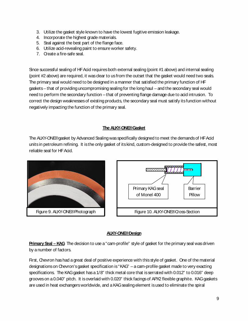
The ALKY-ONE® gasket by Advanced Sealing was specifically designed to meet the demands of HF Acidunits in petroleum refining. It is the only gasket of its kind, custom-designed to provide the safest, mostreliable seal for HF Acid.
ALKY-ONE® Design
Primary Seal – KAG The decision to use a “cam-profile” style of gasket for the primary seal was drivenby a number of factors.
First, Chevron has had a great deal of positive experience with this style of gasket. One of the materialdesignations on Chevron’s gasket specification is “KAG” – a cam-profile gasket made to very exactingspecifications. The KAG gasket has a 1/8” thick metal core that is serrated with 0.012” to 0.016” deepgrooves on a 0.040” pitch. It is overlaid with 0.020” thick facings of APX2 flexible graphite. KAG gasketsare used in heat exchangers worldwide, and a KAG sealing element is used to eliminate the spiral
Figure 9. ALKY-ONE® Photograph
Primary KAG sealof Monel 400
BarrierPillow
Figure 10. ALKY-ONE® Cross-Section
10
winding in Chevron’s “CPFG” style of flange gasket. When properly installed and loaded, the KAG styleof gasket provides a positive seal that is able to withstand years of thermal effects without degradation.
Second, the KAG style gasket had already been submitted to Yarmouth Research Laboratory foremission testing, where it had generated the lowest emission results in the lab’s history – an average of1-ppm over five thermal cycles.
Third, the KAG gasket does not fall under ASME B16.20 standards, so its dimensions can be modified andadapted to meet the specific requirements of an application. This allowed the sealing element to bedesigned to generate seating loads far higher than what are generated in most spiralwounds. Thisfreedom of design also permitted the outer diameter of the KAG sealing element to be sized to takeadvantage of the best part of the raised faces – the area that typically lies just beyond the outside of thewindings in a spiralwound gasket.
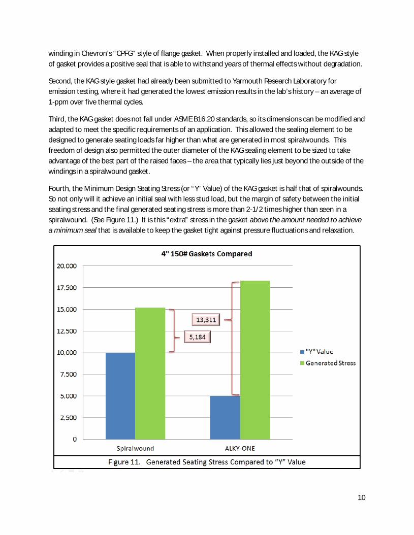
Fourth, the Minimum Design Seating Stress (or “Y” Value) of the KAG gasket is half that of spiralwounds.So not only will it achieve an initial seal with less stud load, but the margin of safety between the initialseating stress and the final generated seating stress is more than 2-1/2 times higher than seen in aspiralwound. (See Figure 11.) It is this “extra” stress in the gasket above the amount needed to achievea minimum seal that is available to keep the gasket tight against pressure fluctuations and relaxation.

11
Secondary Seal – E-PTFE (Barrier Pillow) The natural choice for the secondary seal – used to preventacids from reaching the flange faces – is expanded polytetrafluoroethylene (or E-PTFE). Best known byits DuPont trade name Teflon®, this material is virtually inert to a wide range of chemicals. Theexpanded form of this material is soft and supple, and easily conforms to metal flange faces. From thepoint of first flange contact until the ALKY-ONE® gasket is fully compressed, the ¼” thick barrier pillowundergoes 0.110” compression – much more than is seen on other styles of alkylation gaskets. This highamount of deformation – combined with the suppleness of the material – allows excellent conformationto the flange faces.
This barrier pillow is joined to the primary seal by use of an attachment ring that is machined onto theKAG element. The overlapping fit provides a secure, permanent joining without the use of adhesives.
The soft, compressible nature of E-PTFE also enhances the performance of the primary KAG seal. Sincethe force to compress the barrier pillow comes from the same studs that compress the KAG seal, anyload required by the pillow takes away from the amount of stud stress available to compress theprimary seal. Stress/Compression tests performed on the Flange Assembly Demonstration Unit(discussed below) show that the barrier pillow takes only a small fraction of the bolt load, ensuring thatthe KAG seal develops the stress needed to do its job.
Fire Safety Testing
Yarmouth Research Laboratory was commissioned to determine if the ALKY-ONE® is a fire-safe gasket.The test was performed on a 6” 300# gasket using the API 6FB test protocol. In this test a flangepressurized to 550-psi is held at 1200°F for 15 minutes. The flange is then cooled, depressurized andrepressurized. To be considered fire safe, the leakage at the flange after repressurization can be nomore than 25.6 ml/min. The ALKY-ONE® gasket passed the test with a leak rate of 0 ml/min. (Resultsavailable on request.)
The ease with which the ALKY-ONE® passed this fiery ordeal was not unanticipated, as both the Monel400 base metal and the APX2 flexible graphite are fire-safe materials. Furthermore, the design of theKAG seal element produces a much higher clamping load than normal gaskets – providing reserve stressto help it resist any thermally induced relaxation at the joint.
Of course fire-safety isn’t just about bragging rights. In an HF Alkylation Unit a fire would be a hugethreat to human safety – especially if the gaskets failed in a manner that released HF Acid to theatmosphere. Fire fighting is hazardous enough under the best of conditions, but the addition of HF Acidcould create a nightmare scenario.
Since the E-PTFE barrier pillow of the ALKY-ONE® gasket will not stand up to the heat of a fire – aproblem common to all PTFE-based gaskets – the gaskets would need to be replaced as a part of aplanned maintenance turnaround to restore the unit’s integrity following a fire. However because thegasket is fire-safe – because the primary seal does not leak – gasket replacement can be done under
12
controlled conditions after process lines have been cleaned up and depressurized. Cleaning up processlines is a lot harder if all the gaskets are leaking!
Comparative Test Result to Brand X
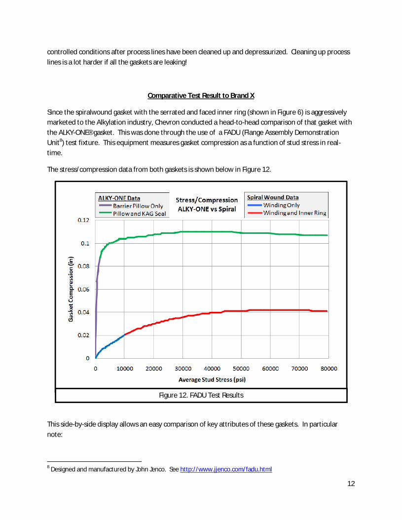
Since the spiralwound gasket with the serrated and faced inner ring (shown in Figure 6) is aggressivelymarketed to the Alkylation industry, Chevron conducted a head-to-head comparison of that gasket withthe ALKY-ONE® gasket. This was done through the use of a FADU (Flange Assembly DemonstrationUnit8) test fixture. This equipment measures gasket compression as a function of stud stress in real-time.
The stress/compression data from both gaskets is shown below in Figure 12.
This side-by-side display allows an easy comparison of key attributes of these gaskets. In particularnote:
8 Designed and manufactured by John Jenco. See http://www.jjenco.com/fadu.html
Figure 12. FADU Test Results

13
1. The total amount of compression that the gaskets undergo is dramatically different. Thespiralwound sees a total of 0.042” compression, while the ALKY-ONE® gasket sees about 0.110”– over 2-1/2 times as much!
2. The amount of compression on the inner seal – the component that prevents HF acid fromreaching the sealing surfaces – is even more dramatic. The inner portion of the spiralwoundonly compresses in the upper part of the curve – the portion in red. That compression is about0.022”. On the ALKY-ONE® gasket the inner pillow is being compressed throughout the entiretightening operation, or about 0.110” – 5 times as much! It is this degree of compression thatallows the barrier pillow to conform to irregularities in the flange faces, providing a positiveinner seal.
3. The amount of force required to compress the inner seal is also dramatically different. Thebarrier pillow on the ALKY-ONE® gasket compresses quickly with very little stud force, as shownby the quickly ascending purple portion of the curve. This demonstrates that once the flangescontact the KAG seal very little of the stud load is diverted into further compression of thebarrier pillow. On the spiralwound the exact force required by the inner seal is hard to separate,because it is only compressed in the top portion of the curve (in red) when both the spiralwoundand inner ring are being compressed at the same time. However as the faces of the inner ringare more densely compressed they require an increasing amount of stud load. Since the innerring becomes the “high point” in the joint preventing the spiral winding from furthercompression, it is assumed that a large portion of the bolt load is transferred to the inner ringinstead of the outer spiralwound winding.
4. The point at which the gaskets reach maximum compression is telling. The ALKY-ONE® gasketreaches this point with only 29,000-psi stud stress. The spiralwound gasket requires almost53,000-psi stud stress – almost twice as much. The reason for this is simply that thespiralwound gasket with the inner cam-profile seal is spreading the stud load over a much largergasket area, so it is less efficient in compressing the gasket. With the ALKY-ONE® gasket thereverse is true. Since the area of compression is smaller than even a standard spiralwoundgasket, it more efficiently compresses the primary seal. This enables it to quickly consolidatethe flexible graphite faces and come to tightness.
What is important to note is that radical differences in the shape of the charted data for these twoproducts is a reflection of the very real physical differences in the products. The quick ascension of theALKY-ONE® graph line shows the soft, supple barrier pillow. But when the graphite faces of the KAG sealare contacted, the line immediately begins a rapid curve as the faces are quickly consolidated and thegasket begins to build seating stress. The gasket comes to tightness quickly because the size of the KAGseal has been purposely designed to produce this result.
The opposite is true for the spiralwound gasket with the inner seal. The very flat curve shows that ittakes a lot of bolt force to compress. The fact that the red portion of the curve takes so long to flattenjust shows that the bolt load is gradually being spread out over a larger area.

14
All of this is readily seen on this FADU comparison.
The FADU test, however, does not show the gasket seating stress that is developed at full torque. Figure13 compares the generated gasket seating stress for the ALKY-ONE® gasket to the spiralwound gasketwith a cam-profile inner rings. The values displayed were calculated at Chevron’s recommended bolttorque for the given flange size.
Chevron recommends torquing the 5/8” studs on a 4” 150# gasket (the size tested in the FADU test) to120 ft-lbs. At that level of tightness the primary seal on the ALKY-ONE® gasket experiences about18,300-psi of seating stress – a level high enough to ensure long-term sealing in spite of relaxation andother thermal effects. By comparison, the spiralwound that has been “enhanced” by the inclusion of aninner cam-profile gasket is attempting to seal a much wider area. As a result, the average full-widthgasket seating stress is reduced to only 8,900-psi – which is much less than the recommended minimumload on a spiral sealing element. Furthermore, the gasket lacks reserve stress to keep it tight when itundergoes relaxation.
While gasket stresses will vary significantly for 300# and higher class spiralwound gaskets across thedifferent pipe sizes, the ALKY-ONE® gasket has been engineered to obtain a consistently high gasketstress at the maximum pressure the flanges is rated for when recommended stud stresses are applied.
Figure 13. Seating Stresses at Full Torque Compared

15
These stud stresses have been engineered to work effectively with both B7 and B7M studs (which havean 80,000 psi minimum yield strength) in weld neck flanges.
Conclusion
The ALKY-ONE® gasket, designed specifically for HF Alkylation services, addresses and resolves the majorsources of sealing difficulty that have plagued that industry. It develops a more-positive seal to preventleakage of HF Acid, while also providing a more supple, adaptive seal to prevent acid intrusion into theflange interface. Its construction from only premium grade materials ensures resistance toenvironmental degradation, while its inherent fire-safety provides an extra level of protection againstunforeseen incidents.