advanced serial data logger - agg software · query your instruments directly from advanced serial...
TRANSCRIPT

© 1999-2016 AGG Software
PRINTED MANUAL

All rights reserved. No parts of this work may be reproduced in any form or by any means - graphic, electronic, ormechanical, including photocopying, recording, taping, or information storage and retrieval systems - without thewritten permission of the publisher.
Products that are referred to in this document may be either trademarks and/or registered trademarks of therespective owners. The publisher and the author make no claim to these trademarks.
While every precaution has been taken in the preparation of this document, the publisher and the author assume noresponsibility for errors or omissions, or for damages resulting from the use of information contained in thisdocument or from the use of programs and source code that may accompany it. In no event shall the publisher andthe author be liable for any loss of profit or any other commercial damage caused or alleged to have been causeddirectly or indirectly by this document.
Printed: 29.11.2016
Advanced Serial Data Logger
© 1999-2016 AGG Software
Publisher
AGG Software
Production
© 1999-2016 AGG Softwarehttp://www.aggsoft.com

IContents
© 1999-2016 AGG Software
Table of Contents
Part 1 Introduction 1
................................................................................................................................... 11 About Advanced Serial Data Logger
................................................................................................................................... 22 Glossary
Part 2 License, Registration andtechnical support 4
................................................................................................................................... 41 License
................................................................................................................................... 52 Limitations
................................................................................................................................... 53 How to register
................................................................................................................................... 64 Support
Part 3 Installation 6
................................................................................................................................... 61 System requirements
................................................................................................................................... 62 Installation process
Part 4 Program use 6
................................................................................................................................... 61 Getting started
................................................................................................................................... 82 Introduction
................................................................................................................................... 93 Data flow diagram
................................................................................................................................... 104 Work complete
................................................................................................................................... 105 Useful advices
................................................................................................................................... 116 Configuration
......................................................................................................................................................... 11Serial port
.................................................................................................................................................. 11Serial (COM) port
......................................................................................................................................................... 17Additional parameters
.................................................................................................................................................. 17Data view change
.................................................................................................................................................. 18Date/time configuration
.................................................................................................................................................. 19Name and security
......................................................................................................................................................... 21Log files
.................................................................................................................................................. 21Log rotation
.................................................................................................................................................. 23Log f ile access
.................................................................................................................................................. 24Log deletion
......................................................................................................................................................... 25Modules
.................................................................................................................................................. 25Introduction & setup
.................................................................................................................................................. 29OPC server
................................................................................................................................... 327 Program options
......................................................................................................................................................... 32Window view
......................................................................................................................................................... 34Date/time stamp view
......................................................................................................................................................... 35Protocol and errors handling
......................................................................................................................................................... 36Service mode on Windows 2000+
.................................................................................................................................................. 36Configuration
.................................................................................................................................................. 40Window s Vista+ notes

Advanced Serial Data LoggerII
© 1999-2016 AGG Software
......................................................................................................................................................... 41Restart & Security
Part 5 Serial communications overview 0
................................................................................................................................... 01 RS-232
................................................................................................................................... 02 DB9 (9 pin) RS-232 port pinout
................................................................................................................................... 03 DB25 (25 pin) RS-232 port pinout
................................................................................................................................... 04 RS-232 loopback devices
................................................................................................................................... 05 RS-232 data transfer cables
Part 6 Having problems? 42
................................................................................................................................... 421 Program doesn't run or work
................................................................................................................................... 432 FAQ
1Introduction
© 1999-2016 AGG Software
1 Introduction
1.1 About Advanced Serial Data Logger
Advanced Serial Data Logger inputs RS232 data directly into file, Excel, Access, or any Windowsapplication. Advanced Serial Data Logger provides real-time data collection from any serial device orinstrument. Send and receive RS232 data across a RS232 port or RS485 port with hardwareconverter.
Advanced Serial Data Logger captures serial data, custom tailors it to your needs, then extract bitsof data from data packets and transfers the data to any Windows or DOS application - either bysending keystrokes to the application's window, by passing the data through DDE (Dynamic DataExchange) conversations, ODBC, OLE.
Key features of Advanced Serial Data Logger is:
variable data receive;received data output without any changes to file;variable format file forming setting (on time, data, size and etc.);connection parameters flexible setting (baud rate, data bits and etc);data flow hardware and software control;work with RS-485 protocol;work in spy (sniffer) mode;auto program restart in showed time;program message logging;advanced data parser that allows you to parse, filter and format more complex data from moresophisticated devices;data export to any database, for which is ODBC-driver (MS SQL, Oracle, MS Access, MSExcel, dBase and others). On the base of received data, you can spy calls, call's length, callingnumber and etc. After data transmit to any "office" data base (MS Excel, MS Access) you canbuild report of any difficulty without help of professionals.Advanced Serial Data Logger can run as DDE server and can export received data;Advanced Serial Data Logger can use direct connection (use OLE) to Microsoft Excel and writedata directly to rows or columns;you can also define format expressions that allow you to do things like force a specific numberof decimal places in numeric values or force data to contain an exact number or sequence ofcharacters.plug-in modules connection, extending program capabilities. Supporting various operating systems. It runs under all versions starting from Windows 2000,including 32 and 64-bit systems..
Advanced Serial Data Logger also transmits requests or commands out the serial port to control orquery your instruments directly from Advanced Serial Data Logger over ASCII or MODBUS protocol.Think of Advanced Serial Data Logger as a fully customizable serial I/O device driver.
Advanced Serial Data Logger has a simple, menu-driven step by step set-up. Programming is notrequired to configure the software to collect data from and control most serial devices.
Advanced Serial Data Logger also is a Windows NT/2000/XP service that records all data receivedon a serial port to a file on a disk or to other targets. It was originally designed to record telephonetraffic data from a phone system (PBX) for later analysis. However, Advanced Serial Data Logger is
2 Advanced Serial Data Logger
© 1999-2016 AGG Software
generic enough to be useful whenever one-way serial traffic needs to be recorded.
Advanced Serial Data Logger has the capability to run multiple instances simultaneously so thatmultiple ports can be logged.
Unlike most other serial logging applications, Advanced Serial Data Logger runs as a service so thatit starts as soon as the operating system starts and doesn't require a user to log in and run it. It willcontinue to run even as users logon and logoff the workstation.
It is extremely easy to use! The configuration process is fully menu driven and has complete,context sensitive, on-line help. you can easily customize all input to your exact specifications. Onceyou see how easy it is to use Advanced Serial Data Logger, you will never again take data readingsby hand!
Company home page: http://www.aggsoft.com/Software home page: http://www.aggsoft.com/serial-data-logger.htmSerial port hardware reference: http://www.aggsoft.com/rs232-pinout-cable/
1.2 Glossary
ASCII - An acronym for American Standard Code for Information Interchange. ASCII files are plain,unformatted text files that are understood by virtually any computer. Windows Notepad and virtuallyany word processor can read and create ASCII files. ASCII files usually have the extension .TXT (e.g., README.TXT).
Binary File - A file that contains data or program instructions written in ASCII and extended ASCIIcharacters.
Bit - Binary digit in the binary numbering system. Its value can be 0 or 1. In an 8-bit characterscheme, it takes 8 bits to make a byte (character) of data.
Bytes - A collection of eight bits that represent a character, letter or punctuation mark.
Cable - Transmission medium of copper wire or optical fiber wrapped in a protective cover.
Client/Server - A networking system in which one or more file servers (Server) provide services;such as network management, application and centralized data storage for workstations (Clients).
COM port - Short for a serial communication port. Most serial communication softwarecommunicate with a computer through a communication port, and most IBM and IBM-compatiblecomputers support up to four serial ports COM1, COM2, COM3 and COM4. Additional ports can beadded by adding additional hardware.
Data bits - A group of bits (1's and 0's) that represent a single character or byte. Typically, there areseven or eight data bits. During an asynchronous communication (e.g., BitCom connecting toCompuServe), each side must agree on the number of data bits. Data bits are preceded by a startbit and followed by an optional parity bit and one or more stop bits.
Flow control - A method of controlling the amount of data that two devices exchange. In datacommunications, flow control prevents one modem from "flooding" the other with data. If data comes
3Introduction
© 1999-2016 AGG Software
in faster than it can be processed, the receiving side stores the data in a buffer. When the buffer isnearly full, the receiving side signals the sending side to stop until the buffer has space again.Between hardware (such as your modem and your computer), hardware flow control is used;between modems, software flow control is used.
Handshaking - Is the way in which the data flow between computers/hardware is regulated andcontrolled. Two distinct kinds of handshaking are described: Software Handshaking and HardwareHandshaking. An important distinction between the kinds of signals of the interface is between datasignals and control signals. Data signals are simply the pins which actually transmit and receive thecharacters, while control signals are everything else.
PC - abbreviation for a Personal Computer.
Parity - In data communications, parity is a simple procedure of checking the integrity of transmitteddata. The most common type of parity is Even, in which the number of 1's in a byte of data add up toan even number, and None, in which a parity bit is not added.
Ports - A connection point for a cable.
Protocol -A formal description of a set of rules and conventions that govern how devices on anetwork exchange information.
RS232, RS423, RS422 AND RS485 - The Electronics Industry Association (EIA) has producedstandards for RS232, RS423, RS422, and RS485 that deal with data communications. EIAstandards where previously marked with the prefix "RS" to indicate the recommended standard.Presently, the standards are now generally indicated as "EIA" standards to identify the standardsorganization.
Electronic data communications will generally fall into two broad categories: single-ended anddifferential. RS232 (single-ended) was introduced in 1962. RS232 has remained widely used,especially with CNC control builders. The specification allows for data transmission from onetransmitter to one receiver at relatively slow data rates (up to 20K bits/second) and short distances(up to 50' @ the maximum data rate). This 50' limitation can usually be exceeded to distances of200' or more by using low capacitance cable and keeping the data rates down to 9600 baud andlower.
RTS/CTS Hardware handshaking - uses additional wires to tell a sending device when to stop orstart sending data. DTR and RTS refer to these Hardware handshaking lines. you can select whetheryou need to use DTR or RTS individually, or use both lines for hardware handshaking. See also Xon/Xoff.
Stop bits - In data communication, one or two bits used to mark the end of a byte (or character). Atleast one stop bit is always sent.
4 Advanced Serial Data Logger
© 1999-2016 AGG Software
2 License, Registration and technical support
2.1 License
Copyright © 1999-2016 AGG Software.All Rights Reserved
SOFTWARE LICENSE
Trial Limited Version
The trial limited version of this software may be used for evaluation purposes at the user's own riskfor a trial period. At the end of the trial period, the user must either purchase a license to continueusing the software, or remove it from his/her system.
The trial limited version may be freely distributed, provided the distribution package is not modified.No person or company may charge a fee for the distribution of Advanced Serial Data Logger withoutwritten permission from the copyright holder.
Licensed Version
On payment of the appropriate license fee, the user is granted a non-exclusive license to use Advanced Serial Data Logger on one computer (i.e. a single CPU), for any legal purpose, at a time.The registered software may not be rented or leased, but may be permanently transferred, if theperson receiving it agrees to terms of this license. If the software is an update, the transfer mustinclude the update and all previous versions.
Registered customer are entitled to free updates during one year from the date of purchase. Itmeans that during one year you can download and install the latest registered versions of AdvancedSerial Data Logger from our site. If you don't want to purchase an updates, you can use the programforever; it will never expire, but you won't be able to use the latest version. If you purchased thesoftware more than one year ago, you are no longer entitled to free upgrade and technical support;however, you can purchase an updates to the latest version at a special, greatly discounted price,and this updates will allow you to have free updates and technical support for another year. The typeof update license must match the type of your existing license.
Whilst every care has been taken in the construction and testing of this software, it is suppliedsubject to the condition that the user undertakes to evaluate the suitability of the control for his/herpurposes. AGG Software makes no representation of the software's suitability for any purpose, andthe user agrees that AGG Software has no responsibility for any loss or damage occasioned by theuse of this software.
TO THE MAXIMUM EXTENT PERMITTED BY APPLICABLE LAW, THE SOFTWARE ANDDOCUMENTATION ARE PROVIDED "AS IS" AND AGG SOFTWARE DISCLAIMS ALL OTHERWARRANTIES AND CONDITIONS, EITHER EXPRESS OR IMPLIED, INCLUDING, BUT NOTLIMITED TO, IMPLIED WARRANTIES OF MERCHANTABILITY, FITNESS FOR A PARTICULARPURPOSE, CONFORMANCE WITH DESCRIPTION, TITLE AND NON-INFRINGEMENT OF THIRDPARTY RIGHTS.
5License, Registration and technical support
© 1999-2016 AGG Software
TO THE MAXIMUM EXTENT PERMITTED BY APPLICABLE LAW, IN NO EVENT SHALL AGGSOFTWARE BE LIABLE FOR ANY INDIRECT, INCIDENTAL, CONSEQUENTIAL, SPECIAL OREXEMPLARY DAMAGES OR LOST PROFITS WHATSOEVER (INCLUDING, WITHOUTLIMITATION, DAMAGES FOR LOSS OF BUSINESS PROFITS, BUSINESS INTERRUPTION,LOSS OF BUSINESS INFORMATION, OR ANY OTHER PECUNIARY LOSS) ARISING OUT OFTHE USE OR INABILITY TO USE THE SOFTWARE PRODUCT, EVEN IF AGG SOFTWARE HASBEEN ADVISED OF THE POSSIBILITY OF SUCH DAMAGES. IN ANY CASE, AGG SOFTWARE'SCUMULATIVE AND ENTIRE LIABILITY TO YOU OR ANY OTHER PARTY FOR ANY LOSS ORDAMAGES RESULTING FROM ANY CLAIMS, DEMANDS OR ACTIONS ARISING OUT OF ORRELATING TO THIS AGREEMENT SHALL NOT EXCEED THE PURCHASE PRICE PAID FORTHIS LICENSE.
Should any term of these terms and conditions be declared void or unenforceable by any court ofcompetent jurisdiction, such declaration shall have no effect on the remaining terms hereof.
If you do not agree to these conditions you should not install this software.
2.2 Limitations
Program is distributed on shareware terms. This means limited and unavailable secondary programpossibilities, which become valuable or available after program registration. To register the programread here .In trial version of our program are the following limits:
Trial period is limited by 21 days. After that time program won't work until it is registered. Continuous program work time is limited. After set period a message will be displayed andprogram stops its work; All data export modules can handle first 100 records only;In spy mode you can receive only first 65535 bytes.
2.3 How to register
The program is distributed on shareware terms. This signifies limited or unavailable many features ofthe program, getting of full value or available after program registration.
If you'd like to be a registered user, to get information about the release of new versions, to usetechnical support and, at last, to get access to disabled functions of the program, register yourcopy. For registration, please, read license agreement .
If you want to buy a program through the Internet visit the registration page of our site. On this pageyou can get the newest information about the registration process, and also find an order link. Afteryou've have the form of order registration. Enter your personal information and choose the mostconvenient payment method for you. Further, you'll get notification and follow the notes in it.
More information about services, registration documents, payment means you can get on our registration page of our site.
5
4
6 Advanced Serial Data Logger
© 1999-2016 AGG Software
2.4 Support
Technical questions [email protected]
Common questions [email protected]
Sales questions [email protected]
3 Installation
3.1 System requirements
Windows 2000 Professional - Windowsa 8.1, including x64 and x86 OS, Workstation and ServerOS.
It is necessary to have at least one free COM port, not busy by any device (mouse, for example) toconnect external device.
3.2 Installation process
If any beta-version was installed on your computer, remove it.
Quit of the working Advanced Serial Data Logger on installation time.
Run an installation file.
By default, Advanced Serial Data Logger will be installed to the directory "/Programs Files/AdvancedSerial Data Logger" of your system disk, but you can change this path.
In the standard distributive of Advanced Serial Data Logger are no additional modules files, whichyou can download from our site.
4 Program use
4.1 Getting started
After you have successfully installed Advanced Serial Data Logger, use the following simple steps toconfigure and run it.
Open the Advanced Serial Data Logger program from the Start Menu.

7Program use
© 1999-2016 AGG Software
At program run you get into the main program window (fig. 1.1.1), main elements of which are themain menu, the data window, the program messages list and the status bar. In the data window willbe viewed formatted data processig. In the messages list are logged information, warning and errormessages. The status bar shows current state of the selected data source, interface errormessages and a number of bytes processed. Through the main menu, placed above the datawindow, you can get access to program settings ("Options/Program settings...") and from themenu "File" (fig. 1.1.2) can open an current log-file or clean the data window.
Fig. 1.1.1 Main program window
Fig. 1.1.2. "File" menu item
By default (after installation), the program has not any data sources configured. If the list of datasources on the toolbar is empty, then the program will ask you to add new configuration. Otherwise,the program will fill in the list of data sources and try to start logging of data sources configured.Yes, of course, all your settings are being saved while exiting from the program and loaded while theprogram start.
Set-Up is as Easy as 1-2-3
Step 1. Configure one or more data sources.
8

8 Advanced Serial Data Logger
© 1999-2016 AGG Software
Click the "Add configuration" button on the toolbar with big green plus and choose communicationparameters for your device. The "COM Port settings" tab of the "Configuration options" dialoglets you configure your settings.
Step 2. Configure log file.
Select the "Log file" header in the configuration dialog window and enable logging for a necessarydata direction.
Step 3. Define how you want the serial data to be parsed and translated .
The "Plug-in" button on the toolbar in the main window or "Modules" tab in the dialog window letsyou specify how to parse, filter and format your data to the fit the exact format required by yourapplication. It also lets you pre-define automatic output strings to be sent to an external device.
Now, the program process and exports data from one or multiple data sources.
4.2 Introduction
Program can work with any kind of serial devices. Before configuring our software, the followingconditions should be executed:
Device should have a RS-232 serial port interface (can be also used a RS-485 interface with anadditional hardware converter);Device is configured to send data to serial port with or without requests from a PC side;You know all information about serial port parameters of your device (If your device useshardware or software flow control (please, read your device's data sheet), then you should knowabout flow control type);Device's serial port is connected with computer serial port with a cable (null-modem or otherspecial cable);Computer's COM port, to which your device is connected is not busy, for example by mousesoftware driver.
How to configure port parameters, you can read in the next chapter "Serial port settings ".
Advanced Serial Data Logger can save data to a log file(s) without any changes (i.e. create rawbinary log files) or write to log files depending on the parser module selected. In the first case youcan view the log file with any hex editor and use this data for further analysis and remaking. In thesecond case you can view data with any text editor. You can find more information about log files inthe "Log rotation " chapter.
You can watch the data in the data window (fig. 1.1.1 ). The data view is fully customizable. Youcan watch data in decimal, hexadecimal or your own format. How to customize data view you canread in the "Data view " chapter and how to customize program view you can read in the "Windowview " chapter.
The data can be exported or transferred to one or more targets. Most simple way is to configure thelog file rotation. But it is small part of all features of Advanced Serial Data Logger. Advanced Serial
11
25
11
21
6
17
32
9Program use
© 1999-2016 AGG Software
Data Logger has many additional modules (so-called plug-ins), that are appreciably extendingpossibilities of the logging software. You can download and install any module supported. Mostmodules are free of charge for our customers. How to install and configure modules you can read inthe "Modules " chapter.
The program and their plug-ins generates many messages and writes they to the list in the mainwindow (fig. 1.1.1 ) and a protocol file, that you can use for administration of the software. Youcan configure types of system messages. More information about it you can read in the "Protocoland errors handling " chapter.
4.3 Data flow diagram
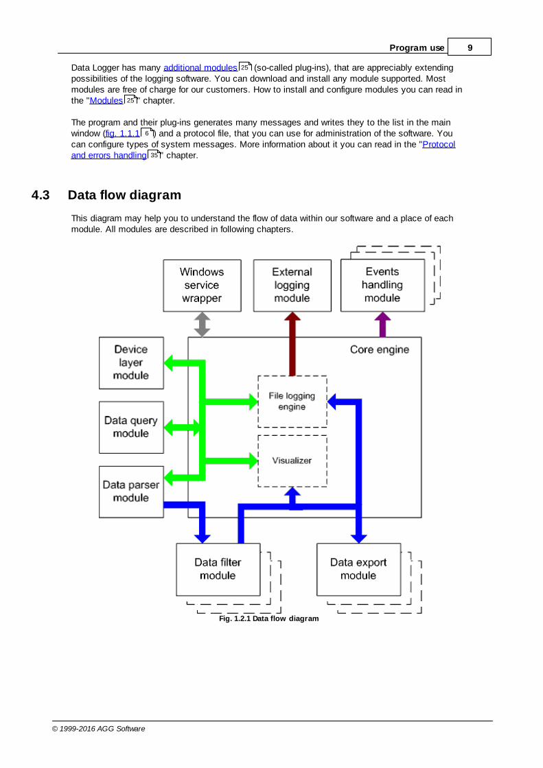
This diagram may help you to understand the flow of data within our software and a place of eachmodule. All modules are described in following chapters.
Fig. 1.2.1 Data flow diagram
25
25
6
35

10 Advanced Serial Data Logger
© 1999-2016 AGG Software
History:
- Binary flow of data (RAW, unformatted data).
- Parsed data (formatted data). The data flow was been separated to data packets andvariables. Each data packet can be interpreted as a row, and each variable can be interpreted as acolumn.
Wires with other colors mark other relations with unstructured data flow.
4.4 Work complete
After program work stop all program settings will be saved in Windows registry. Opened for reading/writing data sources will be automatically closed and will be available for other applications.
4.5 Useful advices
1. Look through hint helps on all window elements - this will help you to get a picture of thiselement's function.
2. You can change all program settings without restarting the program. To transfer settings toanother computer you can do the following:
1. Create a configuration backup from the "File" menu and restore it using the same menu.2. Or export the registry node with all program settings. Start regedit.exe and export the following
registry node:
on Windows x64 HKEY_LOCAL_MACHINE\SOFTWARE\Wow6432Node\AGG Software\Advanced Serial DataLogger
on Windows x32HKEY_LOCAL_MACHINE\SOFTWARE\AGG Software\Advanced Serial Data Logger
3. On another computer import settings to the Windows registry.
Many main window elements have "hot" keys for quick access to its functions.Ctrl+S - analogues to click on "Start/Pause" button on toolbar.Ctrl+C - analogues to click on "Clear" button on toolbar.Ctrl+P - call options window with configuration settings.Ctrl+L - call options window with log file settings.With Ctrl+W hot key You can configure window view.Ctrl+R - show window with program's restart settings.Ctrl+E - Windows NT/2000/XP service settings is available here.Ctrl+M - here you can configure queries, parsers and other modules.
4. You can look at the summary statistic that contains summary about sent and received data,created files etc (View - Statistics)

11Program use
© 1999-2016 AGG Software
5. You can save program settings to an INI file. It may help to install and use several copies of theprogram. You can make your choice from the "Options" menu.
6. The program window can display only last 10 message. The full program log file (if activated) youcan open using the "File - View program protocol file" menu item.
4.6 Configuration
4.6.1 Serial port4.6.1.1 Serial (COM) port
COM port is short for a serial communication port. Most serial communication softwarecommunicate with a computer through a communication port, and most IBM and IBM-compatiblecomputers support up to four serial ports COM1, COM2, COM3 and COM4. Additional ports can beadded by adding additional hardware.
Advanced Serial Data Logger can manipulate with many serial ports in the same time (up to 255serial ports).
You can open serial ports in Advanced Serial Data Logger software in two modes:
1. Spy mode. In this mode the program monitor data flow on ports selected. In this modeAdvanced Serial Data Logger intercept all data exchange between any Windows application andexternal device;
2. Standard. In this mode the program opens a serial port through Windows API functions, andread/write data from/to a serial port as a regular Windows application. In this mode opens aserial port with exclusive rights and other application will not have access to a serial port.
If one or more port are configured already, then Advanced Serial Data Logger is opening these portsand starting logging. If the port is opened successful, then the status bar in the main windowdisplays a status of this port (fig. 1.1.1 ). But, before you should configure serial port parameters.For minimization of configuration we combined serial ports with same settings to the "Configuration".The configuration can include one or more serial ports with identical settings. For example, if youhave many identical devices, that connected to different serial ports, then you can specify portnumbers in one configuration only. But, if you want to use serial port with different settings, then youshould create more than one configurations.
You can create the new configuration by clicking the "Plus" button in the main window (fig. 1.1.1 )or through the "Options" menu. After you clicked the "Plus" button, the dialog window will be opened(fig. 2.1.2). The dialog window contains few sections with parameters. The "COM port" section isdescribed in this chapter.
You can manage the configuration created with a drop down menu near the "Plus" button (fig. 2.1.1).
6
6

12 Advanced Serial Data Logger
© 1999-2016 AGG Software
Fig. 2.1.1 Access to the port configuration
The "COM port settings" tab contains indispensable settings of any serial port: baud rate, data bits,etc. You should configure it with same values, that your external device uses for data exchange.
Fig. 2.1.2 COM port parameters
If you are logging data over RS-485 with an additional hardware converter and your converter doesn'tsupport data direction auto detection, then specify "RS485 interface mode". This option instructsAdvanced Serial Data Logger to set the RTS line at low level while data receiving and vice versa. The

13Program use
© 1999-2016 AGG Software
serial port driver can detect errors while data receiving (for example, bad quality of a connection line).You can specify with the "At data receive error clean incoming buffer" option to ignore datablocks, that contain errors and clean an incoming buffer.
In some cases the program can't open a serial port while starting (for example, the port is alreadyused by other application). With the "Try to open after an unsuccessful attempt" option you canspecify to try to open the serial port again after the interval specified. The program will try to open theserial port until an attempt will successful.
Check line status mode
The Windows communication API provides two methods to check for received data and line/modemstatus changes: API calls (polling) and an event word. The event word is maintained by the Windowscommunications driver. As data is received or line/modem status changes occur, the driver sets bitsin the event word. The application can check the bits to determine if any communication eventsoccurred. If so, the application can make the appropriate API call to clear the event word and retrievethe data or the new line/modem status values.
Windows also provides API calls to retrieve the same status information provided by the event wordbut the API calls are slower. Advanced Serial Data Logger uses the event word by default for thefastest possible performance. Unfortunately, there is at least one communication driver (WRPI.DRV,included with some U.S. Robotics modems) that doesn't appear to support the event word. For thisand similar drivers, select other mode before Advanced Serial Data Logger will receive data.
To rise data transmit adequacy you can use hardware and/or software data flow control (fig. 2.1.3).When using hardware data flow control are used some lines (wires) of connecting cable. Dependingon used lines, you must setup checks against corresponding fields.
Hardware flow control
When the hardware flow control options are an empty, as they are by default, there is no hardwareflow control. The options can be combined to enable hardware flow control.
"Receive flow control" stops a remote device from transmitting while the local input buffer is too full."Transmit flow control" stops the local device from transmitting while the remote input buffer is toofull.
Receive flow control is enabled by including the "Use RTS" and/or "Use DTR" elements in theoptions. When enabled, the corresponding modem control signals (RTS and/or DTR) are loweredwhen the input buffer reaches the 90% size of the buffer. The remote must recognize these signalsand stop sending data while they are held low.
As the application processes received characters, buffer usage eventually drops below the 10% sizeof the buffer. At that point, the corresponding modem control signals are raised again. The remotemust recognize these signals and start sending data again.
Transmit flow control is enabled by including the "Require CTS" and/or "Require DSR" elements inthe options. With one or both of these options enabled, the Windows communications driver doesn'ttransmit data unless the remote device is providing the corresponding modem status signal (CTSand/or DSR). The remote must raise and lower these signals when needed to control the flow oftransmitted characters.

14 Advanced Serial Data Logger
© 1999-2016 AGG Software
Note that flow control using RTS and CTS is much more common than flow control using DTR andDSR.
Software flow control
This routine turns on one or both aspects of automatic software flow control based on the valueassigned to the property.
"Receive flow control" stops a remote device from transmitting while the local receive buffer is toofull. "Transmit flow control" stops the local device from transmitting while the remote receive buffer istoo full.
Receive flow control is enabled by assigning "On receiving" or "Both" to the "Type" property. Whenenabled, an XOff character is sent when the input buffer reaches the level 10% size of the buffer. Theremote must recognize this character and stop sending data after it is received.
As the application processes received characters, buffer usage eventually drops below the level 10%of the buffer. At that point, an XOn character is sent. The remote must recognize this character andstart sending data again.
Transmit flow control is enabled by assigning "On transmitting" or "Both" to the "Type" property. The10% and 90% size of the buffer are not used in this case. When transmit flow control is enabled, thecommunications driver stops transmitting whenever it receives an XOff character. The driver does notstart transmitting again until it receives an XOn character or the user sets software flow control to"None'.
Software data flow control can be setup on receive, transmit or both modes, but so as the greatnumber of device doesn't need data sending, select only control mode "On receive". In case ofactivation of data transmit control remote object (in our case your device) can send special codes,signalizing about data transmit stop or start. On default, received from device character 0x11 Hexsignalizes to COM port driver to start data receive and character 0x13 Hex - to stop data receivefrom device.

15Program use
© 1999-2016 AGG Software
Fig. 2.1.3 Data flow control
Spy mode
In this mode Advanced Serial Data Logger doesn't send and receive any data, and only spies dataexchange, made by other programs.To spy received and sent data open COM port before running the given program. If the given programreceives data over COM port, the data exchange process will be displayed in data receive window.Don't forget to set up check box "Spy mode" to spy data receive by the given program (ifnecessary).
To exit Advanced Serial Data Logger close the given program or stop data exchange over COM portin it.
you must close, which data exchange you spies, before closing Advanced Serial Data Logger.
Serial data transfer errors
Line errors can occur during data exchange and displayed in the main program window in the statusbar.
UART receiver parity error - occurs if you configured invalid parity type;
16 Advanced Serial Data Logger
© 1999-2016 AGG Software
UART receiver overrun,UART receiver framing error - occurs if you configured invalid number of stop or data bits;transmit timeout waiting for CTS,transmit timeout waiting for DSR,transmit timeout waiting for RLSD - occurs if you configured invalid hardware flow control or yourserial interface cable isn't wired for hardware flow controltransmit queue is full - occurs if Advanced Serial Data Logger can't send data to remote device; break condition received
Port restart
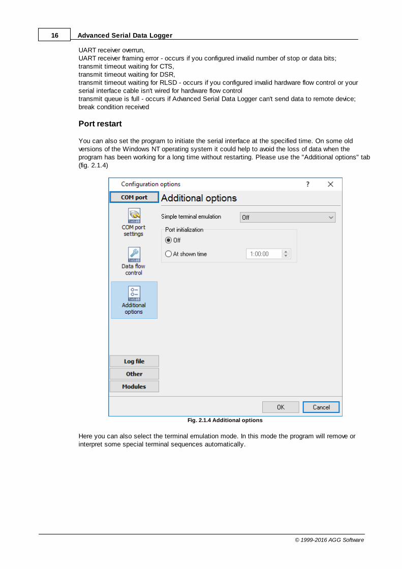
You can also set the program to initiate the serial interface at the specified time. On some oldversions of the Windows NT operating system it could help to avoid the loss of data when theprogram has been working for a long time without restarting. Please use the "Additional options" tab(fig. 2.1.4)
Fig. 2.1.4 Additional options
Here you can also select the terminal emulation mode. In this mode the program will remove orinterpret some special terminal sequences automatically.

17Program use
© 1999-2016 AGG Software
4.6.2 Additional parameters4.6.2.1 Data view change
Fig. 3.1.1. Data view
Data view settings, that can be configured on the "Data view" tab:
1. View characters with code - the program can interpret and decode bytes as characters. Youcan select decoding mode for each characters range. If the range doesn't have thecorresponding character, that's why these data can be displayed only in hexadecimal anddecimal code.
2. You can set up data byte display users format. The directive %d shows to display an decimalcode, the directive %x - hex code. You can set any framing characters before/after the userformat.
3. Highlight data sent on screen - string with sent data will be highlighted by the set color.4. Character set - allows to define the character set of incoming data. Windows - Windows ANSI
character set, DOS - OEM character set.5. Data source custom color - if you've created several configurations then you can define a
custom color for each data source that allows to distinguish data flows on the "All data" page inthe main window.
6. Split strings by data timeout - this option allows to visually split data packets in the program

18 Advanced Serial Data Logger
© 1999-2016 AGG Software
window. A data packets that will be received after the specified interval will be showed on a newline. If this value is set to 0 then data packets will not split.
7. Split continuous data blocks large than - this option allows to visually split continuous dataflow in the program window. The program will show data from a new line every specified interval.
8. Split by characters - this option allows to visually split continuous data flow in the programwindow using the specified symbols. For example (fig. 3.1.1), the program will use a characterwith the 0Ah hexadecimal code that is equal to the "LF" ASCII code.
4.6.2.2 Date/time configuration
This group of options (fig. 3.2.1) allows you to configure how data and time stamps appear in the logfile and on the screen. You can configure the stamp format in the program options .
Fig. 3.2.1 Time stamp configuration
Add to display output for data sent - the time stamp will be added for the sent data displayed onthe screen. The stamp will be added according to the timeout (if the data flow is uninterrupted) orwhen a data packet is sent.
Add to display output for data received - the same but for the received data.
Add if data direction has been changed - if the program is sending and receiving data, the time
34
19Program use
© 1999-2016 AGG Software
stamp will be also added when the data transfer direction changes (sending/receiving).
Add for data packets - if the data is displayed after it is processed, the stamp will be added toeach processed data packet.
Add at begin of file - the stamp will be added at the beginning of every new log file.
Stamp timeout - if the data flow is uninterrupted, the stamp will be added regularly at the intervalspecified in milliseconds.
File prefix/postfix character(s) - the program will use these characters instead of those specifiedin the program options while writing data to a file. For example, it allows you to add the new linecharacter or another sequence of characters before or after the stamp. Example: >#0D#0A
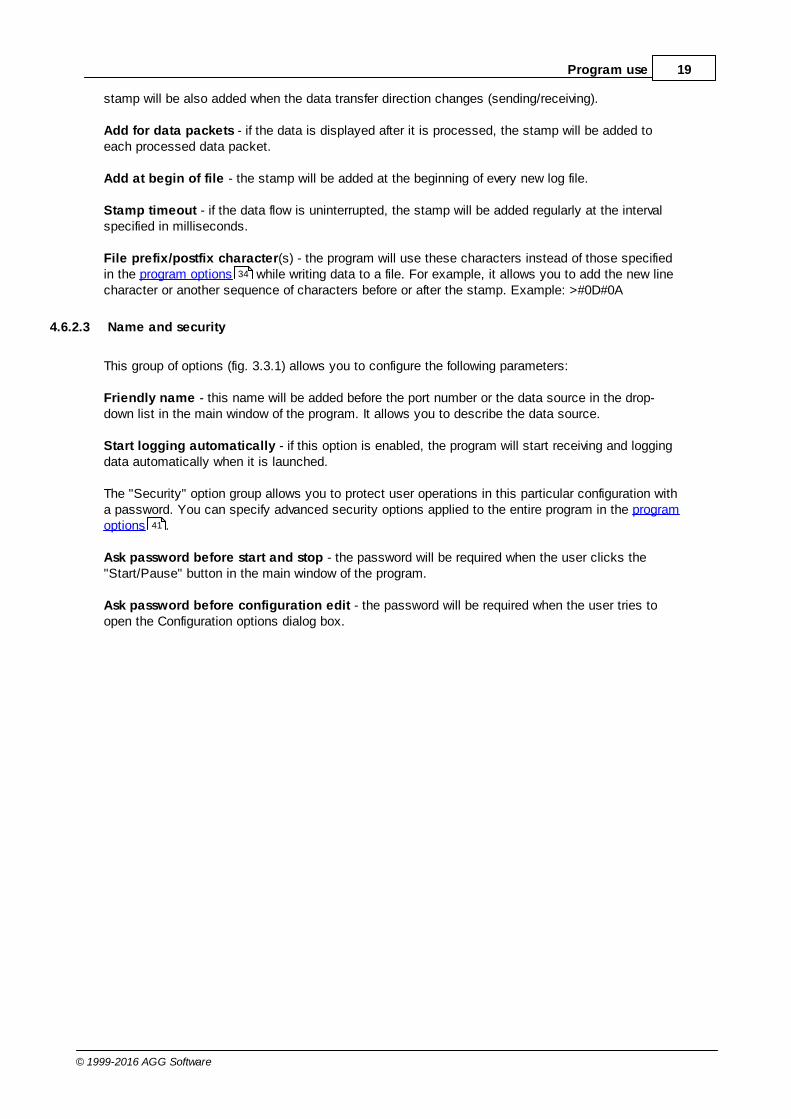
4.6.2.3 Name and security
This group of options (fig. 3.3.1) allows you to configure the following parameters:
Friendly name - this name will be added before the port number or the data source in the drop-down list in the main window of the program. It allows you to describe the data source.
Start logging automatically - if this option is enabled, the program will start receiving and loggingdata automatically when it is launched.
The "Security" option group allows you to protect user operations in this particular configuration witha password. You can specify advanced security options applied to the entire program in the programoptions .
Ask password before start and stop - the password will be required when the user clicks the"Start/Pause" button in the main window of the program.
Ask password before configuration edit - the password will be required when the user tries toopen the Configuration options dialog box.
34
41

20 Advanced Serial Data Logger
© 1999-2016 AGG Software
Fig. 3.3.1. Name and security
21Program use
© 1999-2016 AGG Software
4.6.3 Log files4.6.3.1 Log rotation
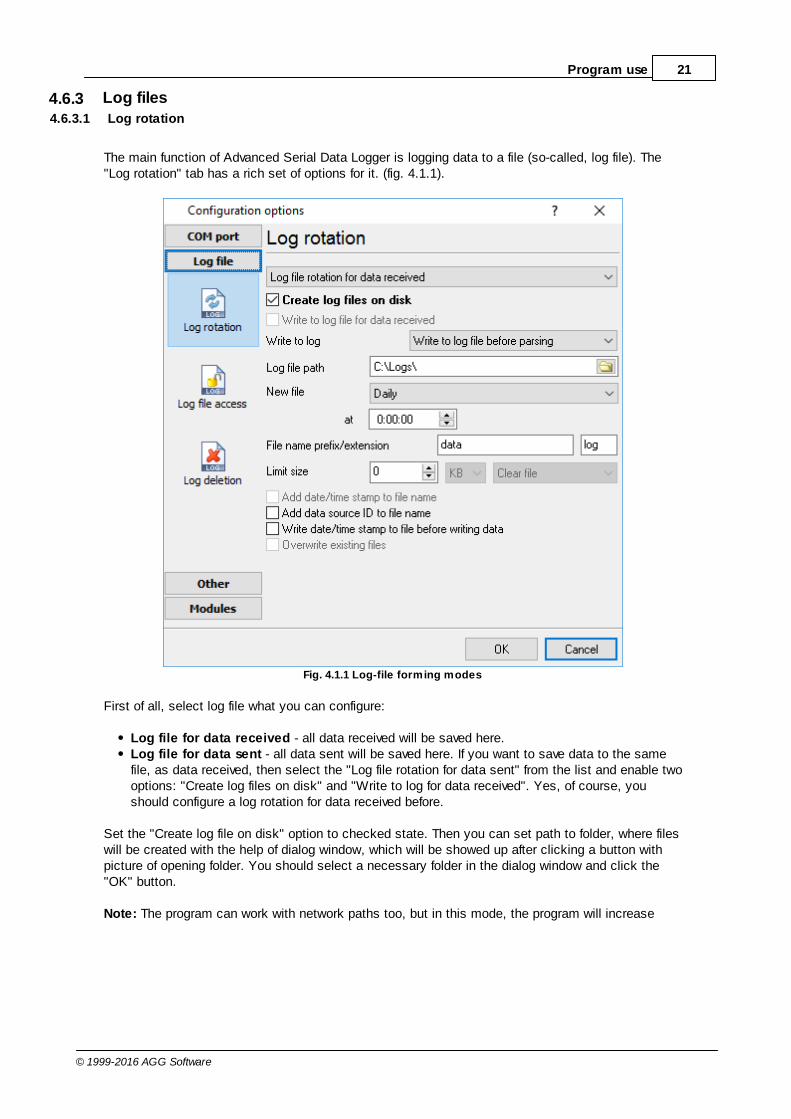
The main function of Advanced Serial Data Logger is logging data to a file (so-called, log file). The"Log rotation" tab has a rich set of options for it. (fig. 4.1.1).
Fig. 4.1.1 Log-file forming modes
First of all, select log file what you can configure:
Log file for data received - all data received will be saved here.Log file for data sent - all data sent will be saved here. If you want to save data to the samefile, as data received, then select the "Log file rotation for data sent" from the list and enable twooptions: "Create log files on disk" and "Write to log for data received". Yes, of course, youshould configure a log rotation for data received before.
Set the "Create log file on disk" option to checked state. Then you can set path to folder, where fileswill be created with the help of dialog window, which will be showed up after clicking a button withpicture of opening folder. You should select a necessary folder in the dialog window and click the"OK" button.
Note: The program can work with network paths too, but in this mode, the program will increase
22 Advanced Serial Data Logger
© 1999-2016 AGG Software
data flow over a network and can be failed with exceptional errors.
A log file name can be stamped with date and time. In this case a new log file is createdperiodically. The time stamp format depends on the selected period. For instance, if the "File nameprefix" field is set to "sample", the "File extension" field to "log" and the "File name format"option is "Daily", then each log file created will have the format "sampleYYYYMMDD.log". On March21st, 2003, the log file will be "sample20030321.log". Please, note, that the final extension (after thefinal period), remains at the end of the file name.
Log rotation mode is defined by the following key parameters:
File name prefix - text string, which will be added at file name beginning;File name extension - text string, which will be a file extension (characters after dot);
Limit size - the "Limit size" field specify the maximum size in kilobytes of any log file. If you'llspecify zero size, then the file size will not limited. You may select from the following modes:1. Clear file - if the log file size will exceed the limit specified, then the log file content will be
deleted and file filling will start from beginning.2. Rename old - if the log file size will exceed the limit specified then the existing log file will be
renamed.3. Shift (no threshold) - the older data over the limit specified will removed from the log file.4. Shift (with threshold). In this mode the program will wait when the file size will exceed the limit
specified + the threshold value. After this, the older data over the limit specified will removed fromthe log file.
If the program works continuous for a long time, it is possible that the log file will have large size andthis file will be inconvenient for looking and analysing. For this there is the possibility to create filesin dependence with the time on PC. You can select one variant predefined or set up new one:
Daily - file will be created with name containing prefix, and date in format DDMMYYYY, whereDD is two-digit day sign, MM is two-digit month sign and YYYY is four digits of the current year.The file name extension will be added at the end of file;Monthly - file will be created with name containing prefix, and date in MMYYYY format. The filename extension will be added at the end of file;Each data packet in different file - in this mode the program splits data flow to a different file.In this mode you should configure the parser or the program will split a data by timeout about300 ms.Don't create new file - in this mode the program will write all data to one file. It isrecommended for a small data flow. Otherwise your log file will be too big and a performance ofthe program will fall down;User's format - file will be created with name containing prefix and date in showed by youformat (for example, DDMMYYYY). The file name extension will be added at the end of file. Thefile may not contain format signs, then file name will be constant. You should not usecharacters, that the OS doesn't allows in file name, such as "/,\.*,?" and some others;Weekly - create a new file every week. The file name will contains a week number;After data timeout - the program will create a new file if the program didn't receive any data atthe specified interval.Hourly - file will be created with name containing prefix, and date in format YYYYMMDDHH,where HH is two-digit hour sign, DD is two-digit day sign, MM is two-digit month sign and YYYYis four digits of the current year. The file name extension will be added at the end of file;Constantly named file - the current log file will have a constant name. When creating a newfile the existing log file will be saved using the new file name that will contain a data and time

23Program use
© 1999-2016 AGG Software
stamp.
Date and time formatting codes:
d - day, not adding null(1-31).dd - day ,adding null(01-31).ddd - day of the week in text form(Mon-Sat) according to standard, set on this computer.dddd - day of the week in full text form(Monday-Saturday) according to standard, set on thiscomputer.m - month, not adding null(1-12).mm - month, adding null (01-12).mmm - month in text form(Jan-Dec) according to standard, set on this computer.mmmm - month in full text form (January- December) according to standard, set on this computer.yy - year in the form of two last digits(00-99)yyyy - year in the form of four last digits (0000-9999).h - hours, not adding null (0-23).hh - hours, adding null (00-23).n - minutes, not adding null (0-59)nn - minutes, adding null (00-59).s - seconds, not adding null (0-59).ss - seconds, adding null (00-59).
Example: you want to create log file every hour. It is desired that file name starts from "sample_log"and the file extension "txt".
Answer: set file prefix = sample_log_, file extension= txt (without dot!). In file name format showHHDDMMYYYY. Now file will be created every hour. Naturally, you can set any formattingcharacters combination, described higher.
If you want to access to a log file while the program work, then you should configure access modesettings for the log file in the next chapter.
Add date/time stamp to file name - this option is available for modes #4 and #7 and allows to adddate and time to the file name.
Add data source ID to file name - if this options is activated then then the program will append thedata source name at the beginning of the file name. For example, COM1-sample20030321.log.
Write data/time stamp to file before writing data - if this options is activated then then theprogram will write a date/time stamp to a file before each data portion.
Overwrite existing files - this option is available for modes #4 and #7 and allows to delete anexisting log file before creating a new log file.
4.6.3.2 Log file access
During work can be such situations, when it is necessary to get access to a file with current data(current log file) from other applications (for example, for data processing). But while you areaccessing the current log file Advanced Serial Data Logger can't write data to a log file and all dataat this moment will be lost. We recommend to use a temporary file for data storage. It is most safeway. (fig. 4.2.1).
23

24 Advanced Serial Data Logger
© 1999-2016 AGG Software
Fig. 4.2.1 File access mode.
You can select one from following variants:
Ignore and not write - with this mode, the data will be lost;Write to a temporary file, then append - a temporary file will be created, to which writing willbe done. After access to current file will be got, temporary file content will be added to the endof main file. But mind that if file is created in dependence of time, there can be a situation whenat temporary file forming name of the main file will be changed. Then temporary file will be addedto the end of newly created file.Display a message and stop work - data will be lost until dialog window is closed.
You can set up your message text, which will be displayed at writing error to data file. The soundsignal can be on for an additional indication. You can also enable writing a message to a protocolfile.
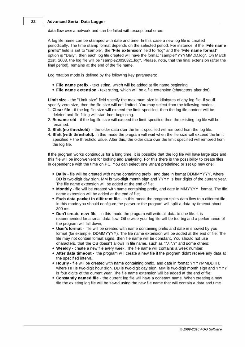
4.6.3.3 Log deletion
The deletion of files (fig. 4.3.1) will help you to avoid stuffing your hard disk with needlessinformation. Log files can be deleted either depending on the time of storing or when the maximalnumber of files is exceeded.
25Program use
© 1999-2016 AGG Software
When deleting files by the time of their storage, the files that were modified last time before thespecified period are deleted.
When controlling the number of files, the files with the oldest modification dates are deleted first.
You can select both variants of file deletion. In that case files will be deleted when either of theconditions is true.
Fig. 4.3.1 Log deletion
4.6.4 Modules4.6.4.1 Introduction & setup
To extend program functionality we implemented plug-ins modules. Module structure lets reduceyour program size and purchase costs (you pay only functionality, which you need), to low downprogram distributive download time, your computer processor load and reduce disk space.
Advanced Serial Data Logger supports few types of modules (fig. 5.1.1 - 5.1.3):
Data query - transmits queries or commands out the data source to control or query your
instruments directly;
26 Advanced Serial Data Logger
© 1999-2016 AGG Software
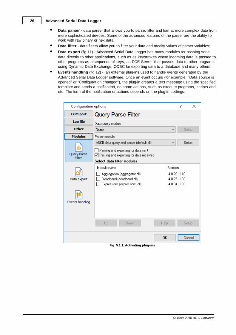
Data parser - data parser that allows you to parse, filter and format more complex data from
more sophisticated devices. Some of the advanced features of the parser are the ability towork with raw binary or hex data;
Data filter - data filters allow you to filter your data and modify values of parser variables;
Data export (fig.11) - Advanced Serial Data Logger has many modules for passing serial
data directly to other applications, such as as keystrokes where incoming data is passed toother programs as a sequence of keys, as DDE Server that passes data to other programsusing Dynamic Data Exchange, ODBC for exporting data to a database and many others;
Events handling (fig.12) - an external plug-ins used to handle events generated by the
Advanced Serial Data Logger software. Once an event occurs (for example: "Data source isopened" or "Configuration changed"), the plug-in creates a text message using the specifiedtemplate and sends a notification, do some actions, such as execute programs, scripts andetc. The form of the notification or actions depends on the plug-in settings.
Fig. 5.1.1. Activating plug-ins

27Program use
© 1999-2016 AGG Software
Fig. 5.1.2 Activating data export plug-ins

28 Advanced Serial Data Logger
© 1999-2016 AGG Software
Fig. 5.1.3 Activating events handling plug-ins
You can parse and export data sent and received (fig. 5.1.1). By default, only data received will beparsed.
Installation
You can easily install a new module. usually, you should start the installation file and click the"Next" button for few times. The installation wizard will detect a place of your Advanced Serial DataLogger software and place a plug-in module and all distributive files to the "Plugins" folder, which isin the program folder (by default X:\\Program Files\Advanced Serial Data Logger\Plugins).
After program restart a module will be loaded and initialized. If module is supported with oursoftware, its short description you will see in modules list (Fig. 5.1.1-5.1.3). Most modules requireadditional settings. If you want to configure the plug-in module, simply click the "Setup" button nearit. If you selected the module and the "Setup" button is not active, then module doesn't haveadditional settings and can work without additional settings. Please, read users manual of acorresponding plug-in for additional information.
Configuration steps
1. Select and configure a query module. You may use a module of this type if you need to send

29Program use
© 1999-2016 AGG Software
some data to your device (for example, initialization strings or request strings).2. Select and configure a parser module. This step is necessary, because filter and export modules
can use parsed data only. If you didn't select the parser module, then you can't configure the datafilter and data export modules.
3. Activate and configure data export modules. You can select one or more modules simultaneously.The program will use selected modules simultaneously. Please, note, the program can' use thedata export module, if you didn't configure the parser module.
4. Activate and configure event modules. You can select one or more modules simultaneously.
4.6.4.2 OPC server
Since the version 2.1.1 Advanced Serial Data Logger has an internal OPC server. It means, that anyOPC compatible client application can get data from Advanced Serial Data Logger without anyadditional software. For connecting to the OPC server our OPC server has an unique attributes (Fig.5.2.1). Before using the OPC server on your PC you should download and install the OPC CoreComponents Redistributable from www.opcfoundation.org (registration required).
Fig. 5.2.1 OPC server parameters
Advanced Serial Data Logger are parsing all incoming data to one or more variables and OPC clientare getting it (fig. 5.2.2). After connecting to the OPC server you will get list of all variables.

30 Advanced Serial Data Logger
© 1999-2016 AGG Software
Fig. 5.2.2 OPC server active items
Clients activity is showed on the "Active clients" tab. The top node is client, below is group of itemsand connected items. By double-clicking, you can get a detailed information about each node.

31Program use
© 1999-2016 AGG Software
Fig. 5.2.3 OPC server clients
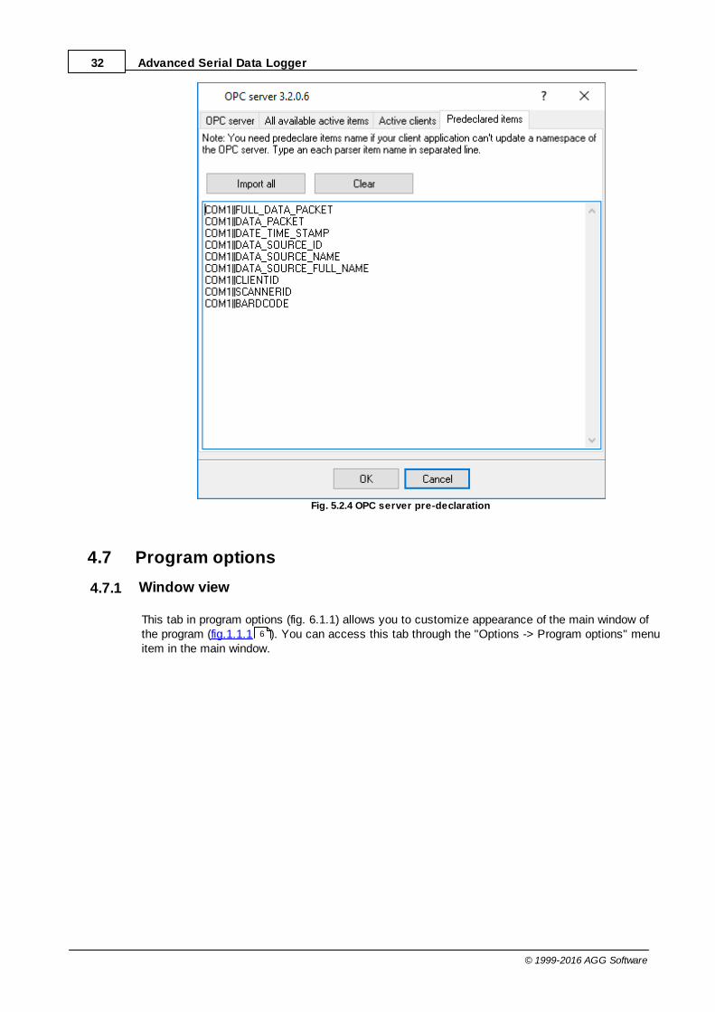
Advanced Serial Data Logger creates new variables at "on-the-fly" mode. The Advanced Serial DataLogger starts without any variables and get it only after first data had been received. If your clientOPC will connect to the OPC server before, than data had been processed, then it will get empty listof variables and your OPC client should poll the OPC server for updating list of variables. If your OPCclient doesn't allow it, then your can pre-define all variables (fig.5.2.4). In this case the OPC serverwill create these variables with empty values, immediate after starting and your OPC client will getthese names while connecting.
32 Advanced Serial Data Logger
© 1999-2016 AGG Software
Fig. 5.2.4 OPC server pre-declaration
4.7 Program options
4.7.1 Window view
This tab in program options (fig. 6.1.1) allows you to customize appearance of the main window ofthe program (fig.1.1.1 ). You can access this tab through the "Options -> Program options" menuitem in the main window.
6

33Program use
© 1999-2016 AGG Software
Fig. 6.1.1 Window view setting
You can set following parameters:
Start in minimized state - at start Advanced Serial Data Logger will automatically put its iconon panel near clock (SysTray fig. 6.1.2);Minimize to SysTray - while the main window of Advanced Serial Data Logger minimizes, theprogram will automatically put its icon to the panel near clock;Show data window - if you specify this option, then the program will display all data in themain window. If you are logging many ports on slow PC, then you can computer CPU load ratewith disabling of this option;Output data on screen in minimized state - if you'll enable this option, then the program willdisplay processed data in minimized state. If you are logging many data sources on slow PC,then you can decrease computer central processor load rate with disabling of this option;Font type - the data will be displayed with this font type in the main window only. Werecommend to use mono-spaced fonts in this field, such as: Terminal, Courier etc.;Screen buffer - at exceeding of value specified the data window will be cleaned;Window view - will let you setup data window view (font color, font type, background color).Transparency - in Windows 2000 and later will let you set transparency of the main window.The most left position is normal window view and most right position is maximum transparency.Wrap words - if you didn't configure a parser module or your data flow doesn't contain a blocksseparator, then your data without this option enabled will be displayed as one long string in thedata window.

34 Advanced Serial Data Logger
© 1999-2016 AGG Software
Fig. 6.1.2 Systray - panel near clock
4.7.2 Date/time stamp view
This group of options (fig. 6.2.1) allows to configure the format of date/time stamps that will be usedin the main program window and log files.
Fig. 6.2.1 Configuring data/stamp view
Prefix/Postfix characters for display output - these options allow to define beginning and endingcharacters of a date/time stamp that will be showed in the program window. When outputting data to

35Program use
© 1999-2016 AGG Software
a log file the program uses individual characters for each configuration.
View mode - allows to select the standard or define the custom format of the date/time stamp.
Font - this group allows to define the color and font of date/time stamp.
Add data direction sign to a stamp - if this option is activated then the program will append TX orRX to the end of the stamp.
Add data source ID to a stamp - if this option is activated then the program will data append datasource ID at the beginning of the stamp. For example, COM1.
4.7.3 Protocol and errors handling
While the program execute, she generates many messages about errors and events. All thesemessages are being registered in a protocol file. This can be start or stop of the program, somemessages from plug-in modules etc. On this tab you can define the kind of messages, which youwant to put a protocol file (fig. 6.3.1). Here you can set maximum protocol file size and a formattingmode. Usually, the protocol file is in a program folder and has the name of the program with the 'log'extension.
18

36 Advanced Serial Data Logger
© 1999-2016 AGG Software
Fig. 6.3.1 Protocol settings
Advanced Serial Data Logger works with three types of messages:
Information messages - this type of messages informs you on operations which are fulfilled inthe current time;Warnings - warns you of possible failures or possible errors. Interference of the user is notrequired, but check is required;Errors - the program has detected an error which elimination needs involvement of the user.
There is the possibility to log following events:
Program messages - messages about start or stop of the program, etc.;Data query - messages which are generated in a data query module;Data parser - messages which are generated in a data parser module;Data export - messages which are generated in a data export module;Other - messages that can not be associated with types above.
You can write each type of messages to a protocol file or/and to the list in the main window. Please,specify necessary options for each message type at "Window" and "File" fields.
If you don't want to allow to grow a protocol file size to an unlimited size, then you can enable the"Clean protocol at program start" or limit protocol file size in the "Size" field.
Some exceptional messages can occur while the program execute. In most cases these messagescrash the program and the most safe way is to restart the program. Please, specify the "Restartprogram at exception" option and the program will be restarted automatically.
If you want look all program messages, then you can disable the "Don't display messages atunhandled exceptions" check box and the program will open the exception message window withdetailed information.
4.7.4 Service mode on Windows 2000+4.7.4.1 Configuration
Windows NT+ services use will let you:
control service on local and remote computers, including remote computers with Windows NT4.0 system;setup actions on emergency service restore in case of failure, for example auto service orcomputer restart (only on computers with Windows 2000 or later);create for services other names and descriptions, to find them easier (only on computers withsystem Windows 2000 or later); run service before user login (password input); service can be setup on automatic start after operation system load.
Note 1: you must be logged in as an administrator in order to change the configuration or control theservice in any way (start, stop, pause, continue).
Note 2: On Windows Vista and later you should start the program with elevated administrator

37Program use
© 1999-2016 AGG Software
privileges.
If you want to use the program as a service application, then, please, go to the "Options -> Programoptions -> Windows service" tab (fig. 6.4.1), then enable the "Use program as a service" check box.Later, please, specify the startup type of the service. There can be following variants:
Fig. 6.4.1 Service settings
1. Automatic - service will be started automatically at every Windows start, before user login;2. Manual - you can start the service application in the "Services" window in the Control panel (fig.
6.4.2);3. Disabled - service can't be started.
If you want to change program settings while service mode, then enable the "Allow service to interactwith desktop" option. In this case, the program will put the icon to the SysTray (fig. 6.4.2). But thenyour interactive service will be restarted while user log off.
38 Advanced Serial Data Logger
© 1999-2016 AGG Software
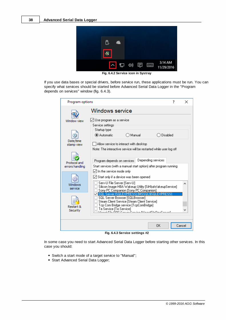
Fig. 6.4.2 Service icon in Systray
If you use data bases or special drivers, before service run, these applications must be run. You canspecify what services should be started before Advanced Serial Data Logger in the "Programdepends on services" window (fig. 6.4.3).
Fig. 6.4.3 Service settings #2
In some case you need to start Advanced Serial Data Logger before starting other services. In thiscase you should:
Switch a start mode of a target service to "Manual";Start Advanced Serial Data Logger;

39Program use
© 1999-2016 AGG Software
Set on the target service at the "Services depend on ASDL" tab;Select mode when you need start these service;Restart Advanced Serial Data Logger.
After you installed the service mode of the program, restart a computer or run the service manuallyfrom the "Services" window in the Control panel (fig. 6.4.4)
Fig. 6.4.4 Manual service run (in Windows 2000)
After start of the service, the service processes names will be displayed in a process list: asdlogsrv.exe and asdlog.exe (fig. 6.4.5). The 'asdlogsrv.exe' application makes interface between the servicemanager and the Advanced Serial Data Logger software. Unlike srvany.exe utility, our service stopssafely.

40 Advanced Serial Data Logger
© 1999-2016 AGG Software
Fig. 6.4.5 Process list
If you want to configure the program as a service, then you must be logged with administrator rights.The service application can be controlled, stopped or removed with help of a command line string.Run asdlogsrv.exe with following parameters:
/? - short help;/I - install service for start in manual mode;/A - install service for start in automatic mode;/D - install service in off state;/R - remove service from computer.
4.7.4.2 Windows Vista+ notes
One of the ways Vista's security was improved was by separating system services and userapplications into separate 'sessions'. Keeping the system services isolated helps to better securethem, but also makes any interactive interface unavailable to the user. That's where the InteractiveServices Detection service comes in. When a service needs to interact with the user, InteractiveServices Detection presents a dialog that will switch the user to the session where the service isrunning so they can interact with the service. For an excellent, detailed description of this, see next

41Program use
© 1999-2016 AGG Software
paragraph.
Many sites recommend disabling this service, but doing so will result in you not being able tointeract with any services that require your attention. This service is run manually by default, sothere is little point to disabling it unless you don't want to be bothered by important information fromthe software you may be trying to run.
Display Name: Interactive Services DetectionService Name: UI0DetectProcess Name: UI0Detect.exeDescription: Enables user notification of user input for interactive services, which enables accessto dialogs created by interactive services when they appear. If this service is stopped, notificationsof new interactive service dialogs will no longer function and there may no longer be access tointeractive service dialogs. If this service is disabled, both notifications of and access to newinteractive service dialogs will no longer function.Path to Executable: %windir%\system32\UI0Detect.exeDefault Startup:
* Home Basic: Manual * Home Premium: Manual * Business: Manual * Enterprise: Manual * Ultimate: Manual
4.7.5 Restart & Security
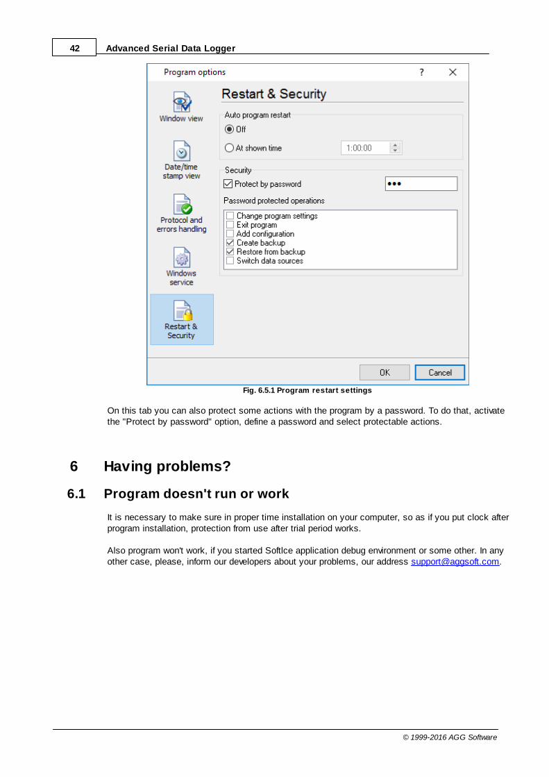
Sometimes the program should be restarted. For example, if you've changed the program settingsremotely and want to reload program automatically with the new settings. To do that, specify thetime for restarting the program on the "Restart & Security" tab in program options "Options->Program options". Just specify the time of day, when the program should be being restarted.
42 Advanced Serial Data Logger
© 1999-2016 AGG Software
Fig. 6.5.1 Program restart settings
On this tab you can also protect some actions with the program by a password. To do that, activatethe "Protect by password" option, define a password and select protectable actions.
6 Having problems?
6.1 Program doesn't run or work
It is necessary to make sure in proper time installation on your computer, so as if you put clock afterprogram installation, protection from use after trial period works.
Also program won't work, if you started Softlce application debug environment or some other. In anyother case, please, inform our developers about your problems, our address [email protected].

43Having problems?
© 1999-2016 AGG Software
6.2 FAQ
Question: Why COM port doesn't open?Answer: Probably, some other program already uses it (COM port). This can be DOS application,for example.
Question: What to do? Answer: Close application, using this communicative port (for DOS application close also DOSsession window). Or use other communicative port. Probably, at start or some program stop wasmade some fatal error and COM port wasn't properly closed.
Question: Is it possible to set variable data transmit rate or transmit 9 data bits?Answer: No, Windows operation system doesn't let such liberties.
Question: What cutoff point type to use: DB25 or DB 9?Answer: It makes no difference, select only in program corresponding COM-port. USUALLY DB25 -COM2, DB9 - COM1
Question: Is cable connection direct or null-modem?Answer: Everything depends on your device cutoff point. Usually it is necessary to use null-modemcable, in which signals are moved apart in this way:
Device | Computer_____________RXD <--> TXDTXD <--> RXDGND <--> GND
if device uses special signals DTR and others and you don't want to use hardware data transmitcontrol, at device side connect 7 and 8 contacts of DB9 cutoff point or analogous DB25 cutoff pointsignals.
More hardware tips and articles you can found on our site http://www.aggsoft.com.
Question: Is data receive becomes at once after program start or data receive must be started? Answer: Everything depends on your device type, usually in device settings is selected to echo viewdata to COM port. If your device doesn't support this mode, write what initialization string must besent to read out data, and we add this possibility to the program.