advanced numerical and experimental studies on ci …
TRANSCRIPT

Journal of Thermal Engineering, Vol. 4, No. 4, Special Issue 8, pp. 2234-2247, June, 2018 Yildiz Technical University Press, Istanbul, Turkey
This paper was recommended for publication in revised form by Regional Editor Bekir Yılbaş 1Department of Mechanical Engineering, Marmara University, Istanbul, TURKEY 2Department of Mechanical Engineering, Istanbul Medeniyet University, Istanbul, TURKEY 3Ford Otosan Company, Gölcük, Turkey *E-mail address: [email protected] Manuscript Received 28 June 2017, Accepted 5 August 2017
ADVANCED NUMERICAL AND EXPERIMENTAL STUDIES ON CI ENGINE
EMISSIONS
M. Z. Gül1, H. Köten2,*, M. Yılmaz1, İ. H. Savcı3
ABSTRACT
In these studies, three important works examined to get ultra-low emission for a single cylinder diesel
engine. The first study was performed for single fuel and compression ratio (CR), intake and exhaust valve timings,
mass flow rate were optimized for a range of engine speed. Then for the same engine injection parameters such as
start of injection (SOI), injector cone angle, and split injection structures were examined to get optimum parameters
for the diesel engine. In CR studies, different combustion chambers were tested according to injector cone angles
and fuel-wall interaction. In the second study, in addition to the above studies, dual fuel compressed biogas (CBG)
and diesel combustion were analyzed under different engine loads both experimentally and computationally.
Optimized single fuel diesel cases were compared with CBG + Diesel dual fuel cases which employed port
injection for CBG fuel. In dual fuel engine applications, CBG fuel and air mixture is induced from intake port and
this air-fuel mixture is ignited by pilot diesel fuel near top dead center (TDC). In dual fuel engine mode, exhaust
emissions reduced considerably especially in NOx and particulate matter (PM) because of methane (CH4) rate and
optimized engine parameters. The third study is focused on aftertreatment systems to minimize residual exhaust
emissions. The emissions of the diesel engines consist of various harmful exhaust gases such as carbon monoxide
(CO), particulate matter (PM), hydrocarbon (HC), and nitrogen oxides (NOx). Several technologies have been
developed to reduce diesel emissions especially NOx reduction systems in last decades. The most promising NOx
emission reduction technologies are exhaust gas recirculation (EGR) system to reduce peak cylinder temperature
that reduces NOx form caused by combustion and active selective catalyst reduction (SCR) system using reducing
agent such as urea-water-solution for exhaust aftertreatment system. In this study, computational fluid dynamic
(CFD) methodology was developed with conjugate heat transfer, spray, deposit and chemical reaction modeling
then emission prediction tool was developed based on the CFD results with deposit prediction mechanism. CFD
and deposit results were correlated with image processing tool in flow test bench.
Keywords: Experimental Study, CI Engine, Emission, Optimization, Aftertreatment
INTRODUCTION
Recently, automotive industry has focused on different techniques to ensure tightened emission rules.
These techniques can be aligned under two main categories: in-cylinder and after-treatment studies. In-cylinder
applications contain optimizing engine parameters to decrease harmful exhaust emissions. After-treatment
applications come into play supplementary role after exhaust port for irreducible emissions. In these investigations,
three different works employed to get ultra-low emissions and high performance for a CI engine numerically and
experimentally.
Multidimensional simulations of the complete engine cycle of diesel engine for single and dual fuel cases
are performed and presented here. Moreover, exhaust after-treatment emission modelling methodology are
developed for NOx reduction system with experimental and numerical methods.
The intake and compression stroke analyses before the combustion has performed to verify the numerical results
with more plausible turbulence model. Then spray and combustion modeling are performed with HCCI strategies
in order to achieve clean combustion concept. Following the power stroke simulations emission are also calculated.
Furthermore, emission treatment is analyzed in detail for a similar CI engine.
CFD studies for a single cylinder diesel engine were modeled using full engine geometry including intake-
exhaust ports and valves. Selected cases were validated by experimental studies. As a result, both in-cylinder

Journal of Thermal Engineering, Research Article, Vol. 4, No. 4, Special Issue 8, pp. 2234-2247, June, 2018
2235
optimization studies and after-treatment application study were satisfied EURO6 emission criteria and increased
combustion performance with new designed engine concept.
The emissions of the diesel engines consist of various harmful exhaust gases such as carbon monoxide
(CO), particulate matter, unburned hydrocarbon (UHC), and nitrogen oxides. Several technologies have been
developed to reduce diesel emissions especially NOx reduction systems in last decades. The most promising NOx
emission reduction technologies are exhaust gas recirculation (EGR) system to reduce peak cylinder temperature
that reduces NOx formation caused by combustion and active selective catalyst reduction (SCR) system using
reducing agent such as urea-water-solution for exhaust aftertreatment system.
Recent years many different emission reduction application strategies were developed. One of the
challenging approach is to remove the EGR from the engine, and design a high NOx conversion efficiency SCR
with reducing agent system. Thus the comprehensive SCR modeling approach is required to design compact after
treatment systems that meet NOx emission legislation level.
NUMERICAL MODELING In engine modeling study, optimum operating conditions in a diesel engine fueled with compressed biogas
(CBG) and pilot diesel dual fuel were examined. One dimensional (1D), three dimensional (3D) computational
fluid dynamics (CFD) codes (AVL-Fire and Star-CD) and multi-objective optimization code were employed to
investigate the influence of CBG-diesel dual fuel combustion performance and exhaust emissions in a CI engine.
In engine studies, 1D engine code and multi-objective optimization code were coupled and evaluated about 15000
cases to define the proper boundary conditions. As an instance, pressure boundary conditions were selected
naturally and turbocharged according to test conditions.
During engine modeling study, different combustion models were employed on moving geometry to get
proper diesel combustion process. For diesel combustion, proffered two combustion models, Eddy Break Up
(EBU) and Extended Coherent Flame Model 3 Zones (ECFM-3Z), were compared and optimum one selected [21].
a) b)
Figure 1. Velocity vector fields perpendicular to the vertical axis at 0.16mm below from cylinder head a) 20 oCA
bTDC for EBU, b) 20 oCA bTDC for ECFM-3Z
a) b)
Figure 2. Temperature contours perpendicular to the vertical axis at 0.16 mm below from cylinder head a) 10 oCA bTDC for EBU, b) 10 oCA bTDC for ECFM-3Z
Journal of Thermal Engineering, Research Article, Vol. 4, No. 4, Special Issue 8, pp. 2234-2247, June, 2018
2236
a) b)
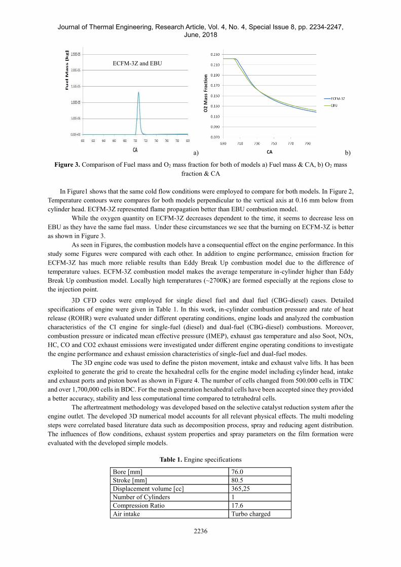
Figure 3. Comparison of Fuel mass and O2 mass fraction for both of models a) Fuel mass & CA, b) O2 mass
fraction & CA
In Figure1 shows that the same cold flow conditions were employed to compare for both models. In Figure 2,
Temperature contours were compares for both models perpendicular to the vertical axis at 0.16 mm below from
cylinder head. ECFM-3Z represented flame propagation better than EBU combustion model.
While the oxygen quantity on ECFM-3Z decreases dependent to the time, it seems to decrease less on
EBU as they have the same fuel mass. Under these circumstances we see that the burning on ECFM-3Z is better
as shown in Figure 3.
As seen in Figures, the combustion models have a consequential effect on the engine performance. In this
study some Figures were compared with each other. In addition to engine performance, emission fraction for
ECFM-3Z has much more reliable results than Eddy Break Up combustion model due to the difference of
temperature values. ECFM-3Z combustion model makes the average temperature in-cylinder higher than Eddy
Break Up combustion model. Locally high temperatures (~2700K) are formed especially at the regions close to
the injection point.
3D CFD codes were employed for single diesel fuel and dual fuel (CBG-diesel) cases. Detailed
specifications of engine were given in Table 1. In this work, in-cylinder combustion pressure and rate of heat
release (ROHR) were evaluated under different operating conditions, engine loads and analyzed the combustion
characteristics of the CI engine for single-fuel (diesel) and dual-fuel (CBG-diesel) combustions. Moreover,
combustion pressure or indicated mean effective pressure (IMEP), exhaust gas temperature and also Soot, NOx,
HC, CO and CO2 exhaust emissions were investigated under different engine operating conditions to investigate
the engine performance and exhaust emission characteristics of single-fuel and dual-fuel modes.
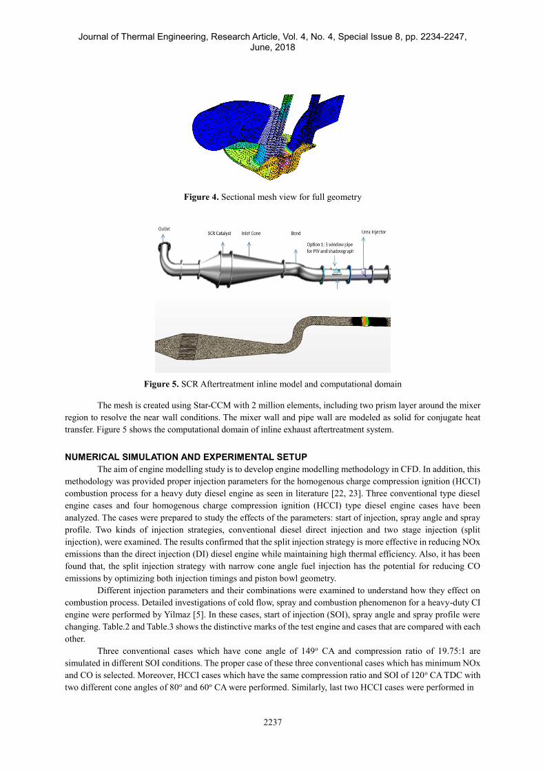
The 3D engine code was used to define the piston movement, intake and exhaust valve lifts. It has been
exploited to generate the grid to create the hexahedral cells for the engine model including cylinder head, intake
and exhaust ports and piston bowl as shown in Figure 4. The number of cells changed from 500.000 cells in TDC
and over 1,700,000 cells in BDC. For the mesh generation hexahedral cells have been accepted since they provided
a better accuracy, stability and less computational time compared to tetrahedral cells.
The aftertreatment methodology was developed based on the selective catalyst reduction system after the
engine outlet. The developed 3D numerical model accounts for all relevant physical effects. The multi modeling
steps were correlated based literature data such as decomposition process, spray and reducing agent distribution.
The influences of flow conditions, exhaust system properties and spray parameters on the film formation were
evaluated with the developed simple models.
Table 1. Engine specifications
Bore [mm] 76.0 Stroke [mm] 80.5 Displacement volume [cc] 365,25 Number of Cylinders 1 Compression Ratio 17.6 Air intake Turbo charged
ECFM-3Z and EBU
Journal of Thermal Engineering, Research Article, Vol. 4, No. 4, Special Issue 8, pp. 2234-2247, June, 2018
2237
Figure 4. Sectional mesh view for full geometry
Figure 5. SCR Aftertreatment inline model and computational domain
The mesh is created using Star-CCM with 2 million elements, including two prism layer around the mixer
region to resolve the near wall conditions. The mixer wall and pipe wall are modeled as solid for conjugate heat
transfer. Figure 5 shows the computational domain of inline exhaust aftertreatment system.
NUMERICAL SIMULATION AND EXPERIMENTAL SETUP
The aim of engine modelling study is to develop engine modelling methodology in CFD. In addition, this
methodology was provided proper injection parameters for the homogenous charge compression ignition (HCCI)
combustion process for a heavy duty diesel engine as seen in literature [22, 23]. Three conventional type diesel
engine cases and four homogenous charge compression ignition (HCCI) type diesel engine cases have been
analyzed. The cases were prepared to study the effects of the parameters: start of injection, spray angle and spray
profile. Two kinds of injection strategies, conventional diesel direct injection and two stage injection (split
injection), were examined. The results confirmed that the split injection strategy is more effective in reducing NOx
emissions than the direct injection (DI) diesel engine while maintaining high thermal efficiency. Also, it has been
found that, the split injection strategy with narrow cone angle fuel injection has the potential for reducing CO
emissions by optimizing both injection timings and piston bowl geometry.
Different injection parameters and their combinations were examined to understand how they effect on
combustion process. Detailed investigations of cold flow, spray and combustion phenomenon for a heavy-duty CI
engine were performed by Yilmaz [5]. In these cases, start of injection (SOI), spray angle and spray profile were
changing. Table.2 and Table.3 shows the distinctive marks of the test engine and cases that are compared with each
other.
Three conventional cases which have cone angle of 149o CA and compression ratio of 19.75:1 are
simulated in different SOI conditions. The proper case of these three conventional cases which has minimum NOx
and CO is selected. Moreover, HCCI cases which have the same compression ratio and SOI of 120o CA TDC with
two different cone angles of 80o and 60o CA were performed. Similarly, last two HCCI cases were performed in

Journal of Thermal Engineering, Research Article, Vol. 4, No. 4, Special Issue 8, pp. 2234-2247, June, 2018
2238
Table 2. Some properties of the test engine
Engine parameters Value
Type
Bore × Stroke
Connecting rod length
Compression ratio
Max. Lift (exhaust)
Max. Lift (intake)
Operating speed
1 Cylinder
104×145 mm
231.2 mm
19.75:1
10,4 mm
9,9 mm
1000 rpm
Table 3. Case studies
Type Case
#
Cone
angle
SOI
CA
Injection
profile
Compression
ratio
Co
nv
enti
o
na
l d
iese
l 0
149o
-20
single 19.75 1 -25
2 -15
Na
rro
w a
ng
le
3 80o
-120
-12
+6
Pre 30%
Main 65%
Post 5%
19.75
4 60o
-120
-12
+6
Pre 30%
Main 65%
Post 5%
19.75
5 80o
-120
-12
+6
Pre 30%
Main 65%
Post 5%
16.27
6 60o
-120
-12
+6
Pre 30%
Main 65%
Post 5%
16.27
different compression ratios of 16.27:1 and same cone angles condition. In similar conditions cases were compared
each other.
The conventional type diesel engine processes are shown in the first three cases. Other cases denote the
Partially Premixed Compression Ignition (PPCI) type diesel engine. Effect of mass flow rate on the emissions and
total heat release were examined in the first three cases. For both three cases total injected mass per cycle is same,
but SOI and end of injection (EOI) are vary, so the mass flow rates are different.
The lower diesel fuel consumption (dodecane-2.14 kg/h) caused the reduction on the combustion
performance as shown in Figure 6 (a). When it came to the 60% load, shown in Figure 6 (a), the diesel combustion
showed slightly higher peak combustion pressure (Pmax = 8.4 MPa) and peak heat release compared to CBG-
diesel case (Pmax = 8.3 MPa). Simultaneously, a greater indicated mean effective pressure (IMEP) was obtained
for single fuel diesel injected fuel mass reached 5.3 kg/h. Figure 6 (b) shows effects of dual fuels on the combustion
characteristics with different engine loads.
The concentrations of NOx emissions for the engine operated with single and dual-fuel combustion modes
were shown in Figure 7. In Figure 7, when the engine load increased, NOx concentrations of all test cases increased
steeply. Significantly lower NOx emissions were emitted within the dual-fuel operations compared to the single
mode at all conducted test ranges. In Figure 7, single fuel diesel combustion cases resulted in higher NOx emissions
at all engine loads compared to dual fuel cases. The reason behind this trend could be explained by the faster
injection and early ignition characteristics of diesel which are visible in previous outcomes of combustion
characteristics.
Journal of Thermal Engineering, Research Article, Vol. 4, No. 4, Special Issue 8, pp. 2234-2247, June, 2018
2239
Figure 6. Combustion characteristics at different engine load. (a) Single fuel (dodecane) cases. (b) Dual fuel
(CBG+dodecane) cases.
Figure 7. NOx for single and dual fuel cases versus CA.
Journal of Thermal Engineering, Research Article, Vol. 4, No. 4, Special Issue 8, pp. 2234-2247, June, 2018
2240
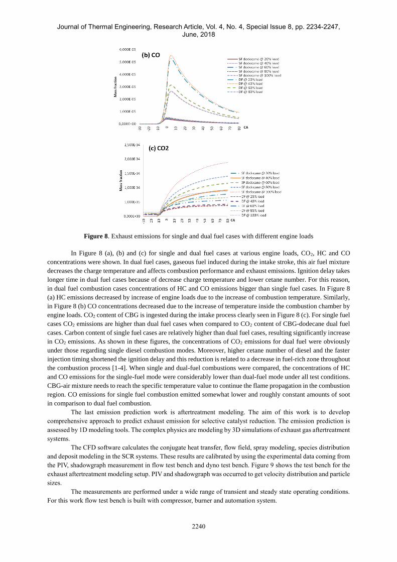
Figure 8. Exhaust emissions for single and dual fuel cases with different engine loads
In Figure 8 (a), (b) and (c) for single and dual fuel cases at various engine loads, CO2, HC and CO
concentrations were shown. In dual fuel cases, gaseous fuel induced during the intake stroke, this air fuel mixture
decreases the charge temperature and affects combustion performance and exhaust emissions. Ignition delay takes
longer time in dual fuel cases because of decrease charge temperature and lower cetane number. For this reason,
in dual fuel combustion cases concentrations of HC and CO emissions bigger than single fuel cases. In Figure 8
(a) HC emissions decreased by increase of engine loads due to the increase of combustion temperature. Similarly,
in Figure 8 (b) CO concentrations decreased due to the increase of temperature inside the combustion chamber by
engine loads. CO2 content of CBG is ingested during the intake process clearly seen in Figure 8 (c). For single fuel
cases CO2 emissions are higher than dual fuel cases when compared to CO2 content of CBG-dodecane dual fuel
cases. Carbon content of single fuel cases are relatively higher than dual fuel cases, resulting significantly increase
in CO2 emissions. As shown in these figures, the concentrations of CO2 emissions for dual fuel were obviously
under those regarding single diesel combustion modes. Moreover, higher cetane number of diesel and the faster
injection timing shortened the ignition delay and this reduction is related to a decrease in fuel-rich zone throughout
the combustion process [1-4]. When single and dual-fuel combustions were compared, the concentrations of HC
and CO emissions for the single-fuel mode were considerably lower than dual-fuel mode under all test conditions.
CBG-air mixture needs to reach the specific temperature value to continue the flame propagation in the combustion
region. CO emissions for single fuel combustion emitted somewhat lower and roughly constant amounts of soot
in comparison to dual fuel combustion.
The last emission prediction work is aftertreatment modeling. The aim of this work is to develop
comprehensive approach to predict exhaust emission for selective catalyst reduction. The emission prediction is
assessed by 1D modeling tools. The complex physics are modeling by 3D simulations of exhaust gas aftertreatment
systems.
The CFD software calculates the conjugate heat transfer, flow field, spray modeling, species distribution
and deposit modeling in the SCR systems. These results are calibrated by using the experimental data coming from
the PIV, shadowgraph measurement in flow test bench and dyno test bench. Figure 9 shows the test bench for the
exhaust aftertreatment modeling setup. PIV and shadowgraph was occurred to get velocity distribution and particle
sizes.
The measurements are performed under a wide range of transient and steady state operating conditions.
For this work flow test bench is built with compressor, burner and automation system.

Journal of Thermal Engineering, Research Article, Vol. 4, No. 4, Special Issue 8, pp. 2234-2247, June, 2018
2241
Figure 9. Schematic of exhaust system layout with emission
Since deposit has complex phenomenological physics for 1D emission prediction tool is required whether
the design meet the emission legislation target. This emission prediction tool should be fast and accurate method
with 3D simulation and deposit effect on the SCR system. Before freezing the design of SCR system, emission
level of design should be predictable whether further design optimizations or advanced SCR technologies are
required. 1D emission tool can predict to different SCR catalyst sizing, chemical kinetic effect and different
aftertreatment system layout on emission level.
RESULTS AND DISCUSSION Figure 10 shows the example of the combustion characteristics of conventional diesel combustion attained
by single injection [16]. In the case of conventional diesel, combustion starts by injection at 15o, 20o, 25o before
Top Dead Centre (bTDC), as shown in Figure 10. In these first three cases, the ignition delay was very short and
ignition had begun during injection event. This led to significant in homogeneity during combustion. Corollary,
high emission results such as NOx and soot could be expected as seen in Figure. 10. NOx emission decreases for
conventional diesel engines when the distance between the start of the injection and TDC is larger. Because of the
high temperature and heat release, NOx emission results higher and soot emission results lower than the other
cases.

Journal of Thermal Engineering, Research Article, Vol. 4, No. 4, Special Issue 8, pp. 2234-2247, June, 2018
2242
Figure 10. Injection rates and results for conventional cases
NOx and soot emissions showed a strong dependence on the injection timing at a constant equivalence
ratio. The peaks of the NOx emissions occurred between -10o and 20o which were slightly advanced of the
injection timing as typical of the operating conditions of a conventional diesel engine as shown in Figure 10. Figure
11 shows the example of the combustion characteristics of PPCI diesel combustion attained by split injection. In
this split injection strategy pre, main and post injections have 35%, 60%, 5% of fuel per stroke respectively with
80o and 60o narrow angle. In these cases, the ignition delay was very long and ignition had begun before main
injection event close to TDC about 23o bTDC. This led to significant homogeneity during combustion. Corollary,
low emission results such as NOx and soot could be expected.
The results for PPCI cases shows that, case3 which is prepared with using 80° cone gives better emission
performance for both soot and NOx emissions relative to case4 with 60° cone angle. PPCI cases were compared
to obtain optimum case for NOx and soot emissions. Figure 12 shows the results for these cases.
The injection profile has a consequential effect on the emissions as seen in the Figure 13. The soot
emission results show that partially-premixed type injection model reduces this emission. However, NOx emission
fraction for case2 is much more than the other cases due to the single type injection of fuel and start of the injection.
The pre-injection (%30 of total fuel per stroke) makes the average temperature in-cylinder higher than the other
cases as seen in the Figure 13. Locally high temperatures (~2700K) are formed especially at the regions close to
the injection point. Same results occur in the case3, case4, case5, case6, which includes %30 pre-injection fuel
Figure 11. Comparison of the results for different the spray angles

Journal of Thermal Engineering, Research Article, Vol. 4, No. 4, Special Issue 8, pp. 2234-2247, June, 2018
2243
Figure 12. Comparison of the best PPCI cases according to emission performance for different compression
ratio
mass. Case3 gives the best results for soot and NOx emissions. Figure 13 shows that there is an improvement on
emissions with narrow cone angles and split injection strategy. The soot and NOx emissions decrease for PPCI
cases which includes narrow spray angles although there is high in-cylinder temperature relative to conventional
cases.
PPCI results show that case3 in which the injector has 80o cone angle results in lowest emissions. On
engine geometry, compression ratio was reduced from 19.75:1 to 16.27:1 by decreasing maximum radius of the
bowl and increasing the depth of the bowl to prevent the immoderately advanced ignition of the pre-mixture formed
by early injection Table 3. Because of its effects on in-cylinder temperature and pressure during the compression
phase, the engine compression ratio has an influence on the auto-ignition phase of the combustion: a reduction
prolongs the air/fuel mixing process before combustion. Different works [6], [7], [8] performed on experimental
single cylinder engines showed this significant advantage.

Journal of Thermal Engineering, Research Article, Vol. 4, No. 4, Special Issue 8, pp. 2234-2247, June, 2018
2244
Figure 13. Effects of the compression ratio on the emissions.
According to soot emission results show to reduce the compression ratio increases emission values. Both
of NOx and soot emission fractions for case5 is much more than for case3 due to compression ratio value. Reducing
compression ratio should be made the average temperature and pressure in-cylinder higher than the other cases but
not. Because of the high temperature and heat release, NOx and soot emission results are higher than other cases.
Same results occur in the case6, which includes less compression ratio value. Case3 gives the best results for soot
and NOx emissions. Case3&5 which use 120 degree CA bTDC as a start of the injection time, has better emission
values than the other two cases.
The results are shown in figure 13 show that although there is a rise on the mass fraction of the soot, the
NOx value for case4 which uses a narrow spray angle of with 60o, is better than case3. The peaks of the temperature
occurred unexpectedly at cases have reduced compression ratio (16.27). Therefore, these two cases have indicated
that the high temperature reaction (HTR) occurs at around 1000–1100 K. The calculated peak of the bulk gas
temperature for reduced compression ratio as shown in Figure 13 was about 1800 K such as conventional diesel
combustion, clearly lower than NOx formation temperature but higher than other PPCI cases.
As the compression ratio reduced, the peaks of heat release rate of HTR rapidly increased and the initiating
timings of the reaction were also retarded. In these cases, the ignition delay was very long and ignition had begun
before main injection event close to TDC about 20o-25o bTDC. This led to significant homogeneity and better
combustion control during combustion. However, higher emissions such as NOx and CO could be unexpected.
Only soot emissions consequently slightly decreased and kept reduction trend. Furthermore, it could be said that
fuel is burned effectively with respect to other cases (Figure 13) especially for case4 has reduced compression
ratio (case6).
CO2, CO and NOx emission results show that the comparison of emissions measurement of the same
engine with the CFD simulation results Table 4. Experimental data is in good agreement with the simulation results
that are obtained at running conditions of case-3.
The efficient design of selective catalyst reduction system is required to NOx reduction mechanism. This
system design is crucial for emission legislation. In this study, comprehensive modeling approach has been
developed to simulate active SCR system based on inline exhaust aftertreatment system from Flow Test Bench [9-
15]. By This method we can understand whether the design/design changes effect on emission.
Three dimensional (3D) simulation of inline exhaust aftreatment system with spray injection of UWS,
evaporation and thermal decomposition processes have been presented results in the present chapter using Star-
CCM [17]. The deposit prediction of the CFD result was correlated with flow lab image processing. Then the
deposit mass increased and ammonia mass flow rate are reduced based on the flow lab test results. The correlated
values of ammonia are passes to emission prediction model. [18]
Table 4. Comparison of emissions obtained from CFD simulation with experimental data.
Emissions [ppm] Experimental CFD
CO2 38140.8 39425.7
CO 9.1 11.4
NOx 109.5 397.2

Journal of Thermal Engineering, Research Article, Vol. 4, No. 4, Special Issue 8, pp. 2234-2247, June, 2018
2245
Figure 14. Velocity vector at the cone k-epsilon
The velocity fields are investigated in details. The turbulence model of the RSM predict in good
agreement of the flow recirculation at the upstream of the catalyst. k-e turbulence model cannot predict the swirl
region upstream of the mixer in Figure 14.
Figure 15. Droplet Distribution across the system at 0.1325 s
The mixers are installed at the downstream of the injector of the inner pipe. They are enhanced droplet
evaporation, breakup and distribution of the spray. [19] The mixer has significant effect on the break-up process.
Figure 15 shows the application of mixer. [20]
Emission results of the inline exhaust aftertreatment system shows high temperature operating point NOx
conversions are %98.
CONCLUSION In this work, three main studies; effects of engine parameters on the diesel engine performance, effects of
dual fuels on the diesel engine performance and aftertreatment system investigations were studied and presented.
Various configurations of compression ratio, injection timing, cone angle and bowl geometry are compared to get
the best performance of the engine. Obtained CFD results are found qualitatively in agreement with the previous
experimental and computational studies in the literature.
In the present studies EBU and new combustion model (ECFM-3Z) is used successfully [21]. Moreover,
on an engine configuration with compression, spray injection and combustion in a DI Diesel engine are
satisfactorily modeled. Effect of combustion chamber design and injection parameters for single and dual fuels in
a DI diesel engine are investigated and presented. Simulations how the injection parameters affect emissions, show
that the emission results under some PPCI circumstances may be highly affected between 5 and 25% by a relatively
small change of injection rates.
The aftertreatment modelling study is for developed numerical simulations for droplet and species show
the dependency of the SCR system to the injection characteristics and flow field parameters. The good agreement
is shown in terms of injection and flow field between numerical model and flow test bench.
The simulation of active SCR system has been performed in spray-wall interaction framework as well.
The multi component Bai impingement model has been adopted into numerical simulation to predict deposit
location but mass of deposit cannot predict well.
The aftertreatment work revealed that Reynolds stress turbulence model is sufficient to model. PIV
measurement and RSM simulations may be employed to directly validate turbulent exhaust flow field and spray
simulation.

Journal of Thermal Engineering, Research Article, Vol. 4, No. 4, Special Issue 8, pp. 2234-2247, June, 2018
2246
In addition to serving their primary purpose of enhancing mixing between exhaust gas and spray, mixers
are quite effective in reducing deposits. Heat transfer via spraying onto a mixer's hot surfaces results in enhanced
boiling and convective heat flux.
The pipe surface temperature is a critical factor due to the deposits that form on the inner pipe walls of
the system. Below a certain critical temperature, wall wetting and ensuing deposit formation are built.
NOMENCLATURE
1D One-Dimensional
3D Three-Dimensional
aBDC After bottom dead center
aTDC After top dead center
BDC Bottom dead center
Bsfc Brake specific fuel consumption (g/kWh)
CA Crank Angle
CAD Crank angle degree
CFD Computational Fluid Dynamics
CI Compression ignition
CO Carbon monoxide
CO Carbon Monoxide
EC European Commission
EGR Exhaust Gas Recirculation
NOx Nitrogen Oxides
PM Particulate Matter
SCR Selective Catalytic Reduction
PPCI Partially Premixed Compression Ignition
ACKNOWLEDGMENTS
These works have been supported by Marmara University BAPKO institution with project no: FEN-B-
101013-0399 and FORD-OTOSAN Company. The authors would like to thank the BAPKO institution for
supporting this research project.
REFERENCES
[1]Kim, M. Y., Yoon, S. H., & Lee, C. S. (2008). Impact of split injection strategy on the exhaust emissions and
soot particulates from a compression ignition engine fueled with neat biodiesel. Energy & Fuels, 22(2), 1260-
1265.
[2]McCormick, R. L., Tennant, C. J., Hayes, R. R., Black, S., Ireland, J., McDaniel, T., ... & Sharp, C. A. (2005).
Regulated emissions from biodiesel tested in heavy-duty engines meeting 2004 emission standards (No.
NREL/CP-540-37508). National Renewable Energy Laboratory (NREL), Golden, CO..
[3]Kim, M. Y., Yoon, S. H., Hwang, J. W., & Lee, C. S. (2008). Characteristics of particulate emissions of
compression ignition engine fueled with biodiesel derived from soybean. Journal of Engineering for Gas Turbines
and Power, 130(5), 052805.
[4]Mustafi, N. N., & Raine, R. R. (2008). A study of the emissions of a dual fuel engine operating with alternative
gaseous fuels (No. 2008-01-1394). SAE Technical Paper.
[5]Yilmaz, M., Köten, H., & Gul, M. Z. (2012). Effects of the injection parameters and compression ratio on the
emissions of a heavy-duty diesel engine. International Journal of Vehicle Design, 59(2/3), 147-163.
[6]Gatellier, B., Ranini, A., & Castagné, M. (2006). New developments of the NADI (TM) concept to improve
operating range, exhaust emissions and noise. Oil & gas science and technology, 61(1), 7-23.
[7]Albrecht, A., Grondin, O., Le Berr, F., & Le Solliec, G. (2007). Towards a stronger simulation support for engine
control design: a methodological point of view. Oil & Gas Science and Technology-Revue de l'IFP, 62(4), 437-
456.
[8]Chauvin, J., Corde, G., Petit, N., & Rouchon, P. (2006). „Experimental air path control of a Diesel engine‟. Les
Rencontres Scientifiques de l’IFP–New Trends in Engine Control, Simulation and Modelling.

Journal of Thermal Engineering, Research Article, Vol. 4, No. 4, Special Issue 8, pp. 2234-2247, June, 2018
2247
[9]Birkhold, F., Meingast, U., Wassermann, P., & Deutschmann, O. (2006). Analysis of the injection of urea-
water-solution for automotive SCR DeNOx-systems: modeling of two-phase flow and spray/wall-interaction (No.
2006-01-0643). SAE Technical Paper.
[10]Mckinley, T. L., & Alleyne, A. G. (2009). A Urea Decomposition Modeling Framework for SCR Systems.
SAE International Journal of Fuels and Lubricants, 2(2009-01-1269), 612-626.
[11]Munnannur, A., & Liu, Z. G. (2010). Development and validation of a predictive model for DEF injection
and urea decomposition in mobile SCR DeNOx systems (No. 2010-01-0889). SAE Technical Paper.
[12]Ström, H., Lundström, A., & Andersson, B. (2009). Choice of urea-spray models in CFD simulations of urea-
SCR systems. Chemical Engineering Journal, 150(1), 69-82.
[13]Zheng, G., Palmer, G., Salanta, G., & Kotrba, A. (2009). Mixer development for urea SCR applications (No.
2009-01-2879). SAE Technical Paper.
[14]Jeong, S. J., Lee, S. J., Kim, W. S., & Lee, C. B. (2005). Simulation on the optimum shape and location of
urea injector for urea-SCR system of heavy-duty diesel engine to prevent NH3 slip (No. 2005-01-3886). SAE
Technical Paper.
[15]Koten H., (2014). “Experimental Investigation and Multidimensional Modeling Of Biogas Effects On The
Diesel Engine Combustion Characteristics” Phd Thesis, Marmara University.
[16]Yilmaz, M., (2009). “Effect of CDC Concept on the Design Parameters of a Heavy Duty PPCI Engine by Use
of Multidimensional Modeling”, PhD Thesis, University of Marmara.
[17]Savci I., (2015). “An Integrated Modeling Approach to Investigate Performance of Selective Catalyst
Reduction” PhD Thesis, University of Marmara.
[18]Abu‐Ramadan, E., Saha, K., & Li, X. (2011). Modeling the depleting mechanism of urea‐water‐solution
droplet for automotive selective catalytic reduction systems. AIChE Journal, 57(11), 3210-3225.
[19]F. Birkhold, (2007).Selektive katalytische Reduktion von Stickoxiden in Kraftfahrzeugen, Stutgart: PhD
Thesis.
[20] Birkhold, F., Meingast, U., Wassermann, P., & Deutschmann, O. (2006). Analysis of the injection of urea-
water-solution for automotive SCR DeNOx-systems: modeling of two-phase flow and spray/wall-interaction (No.
2006-01-0643). SAE Technical Paper.
[21] Koten H., (2009). “Comparison of Various Combustion Models within a Multi-Dimensional Modeling
Applied to Heavy Duty CI Engine” MSc Thesis, Marmara University.
[22] Gul, M. Z., Yılmaz, M., & Köten, H. (2009). Effects of the injection parameters on the emissions of a heavy
duty diesel engine. ASME-IMECE.
[23] Köten, H., Gul, M. Z., & Yılmaz, M. (2010). A CFD Study On Heavy Duty DI Diesel Engine To Achieve
Ultra Low Emissions.