numerical and experimental investigations on …
TRANSCRIPT

Journal of Thermal Engineering, Vol 6, No. 5, pp. 858-872, October, 2020 Yildiz Technical University Press, Istanbul, Turkey
This paper was recommended for publication in revised form by Regional Editor Pouria Ahmadi 1 Department of Mechanical Engineering, Dr. D. Y. Patil Institute of Technology, Pune, S.P. Pune University, India 2 Department of Mechanical Engineering, Pune Institute of Computer Technology, Pune, S.P. Pune University, India *E-mail address: [email protected] Orcid ID: 0000-0002-5033-7846*, 0000-0003-4145-8125 Manuscript Received 14 December 2019, Accepted 16 June 2020
NUMERICAL AND EXPERIMENTAL INVESTIGATIONS ON PERFORMANCE
EVALUATION OF A CONICAL OFFSET VORTEX GENERATOR INSERTS TO
IMPROVE CONVECTIVE HEAT TRANSFER COEFFICIENT
Shivaji V. Mundhe1,2*, Rupa S.Bindu1
ABSTRACT
The passive augmentation technique is widely used by researchers from thermal engineering field and it has
shown excellent results for convective heat transfer rate. This paper shows the numerical and experimental findings
for convective heat transfer characteristics and friction coefficient. Tests were conducted for turbulent flow, using air
as medium through a uniformly heated steel pipe containing a novel kind of insert named as Conical offset Vortex
Generator (COVG). The simulation tests were performed for turbulent flow with varying Reynolds number in the
range 4000 to 50000. The parameters were analyzed during tests are pitch to smooth tube diameter ratio (p/d) and
angle of attack (α). Various simulation tests were carried out with the help of ANSYS Fluent software to optimize the
geometry. The simulation tests were carried out for different angle of attack (α = 15°, 30°, 60°). COVG with angle of
attack (α = 60°) shows more enhancement in heat transfer rate, hence it was used for the experimentation purpose.
The experimentation is conducted for various pitch to diameter (p/d = 1.18, 1.97, 3.94). The numerical and
experimental results show improvement in heat transfer rate as there is decrease in pitch to smooth tube diameter
ratio (p/d) and it also increases the value of friction factor. The reason behind the improvement in heat transfer rate is
that, the braking of thermal boundary layer near the wall surface. Experimental results show the enhancement of
Nusselt number from 3.46 – 6.7.
Keywords: Conical Offset Vortex Generator (COVG), Convective Heat Transfer Coefficient, Angle of
Attack, Pitch to Diameter Ratio
INTRODUCTION
Heat transfer in the laminar and turbulent flow regimes occurs in various engineering applications. The
passive techniques are often used to enhance heat transfer. Various industries viz. refrigeration, air-conditioning,
manufacturing, power generations, process, electronics, chemical, food processing, and space applications utilizes
heat exchangers for heat transfer between two or more fluids at different temperatures [1]. Enhancement of heat
transfer improves the efficiency of heat exchangers. Various methods are used to enhance the heat transfer, which is
broadly classified in to two types active method and passive method. Active method requires the external power such
as jet impingement, magnetic or electric field, vibrations etc. [2]. Passive method uses special types of geometries in
the fluid flow path to improve heat transfer rate [3,4]. Vortex generators create good swirl which can be used to break
the thermal boundary layer and enhance the heat transfer. A vortex generator created with the help of cone was used
by Deshmukh et al. [8] to study the heat transfer and friction factor characteristics. A certain modification is done in
the vortex generator by Chamoli, et al. [18] to investigate thermal characteristics of modified geometry by creating a
hole in it. For this study, some geometrical modification was made to vortex generator and experimental and
numerical tests were carried out.
Journal of Thermal Engineering, Research Article, Vol. 6, No. 5, pp. 858-872, October, 2020
859
Deshmukh, et al. [8] reported the experimental data with the winglet vortex generator made from a cone.
They carried out the experimentation for varying Reynolds number from 10000 to 45000, the average Nusselt
number ratio with and without the insert (Nua/Nus) at constant Reynold number (Re) is found from 1.3 to 5.0. The
Nusselt number ratio (Nua/Nuc) based on equal pumping power is found in the range of 1.0 to 1.8. A similar kind of
insert is used for laminar flow condition by Deshmukh, et al. [9] where Reynold’s number is varied between 250 to
1500. The average Nusselt number ratio with and without the insert (Nua/Nus) at equal Reynolds number (Re) is
found from 5.0 to 15.0. The performance ratio (Nua/Nuc) based on equal pumping power is found in the range of 1.0
to 6.0
Wang, et al. [10] worked on the longitudinal vortex generator insert with the numerical and experimental
analysis. Nusselt number increases from 2.55 to 7.10 with respect to the smooth tube. The friction factor varies from
2.21 to 11.27 with enhancement in overall heat transfer performance from 1.17 to 6.15. Sarviya, et al. [11] reported
the experimental values for the twisted tape to insert with continuous rectangular cut edges with twist ratio 5 and 3
for Reynolds number 4000 to 20000. They observed the improvement in heat transfer rate by 2.21 and 2.23 times
that of the smooth tube and 1.63 to 1.42 times of conventional twisted tape.
Chokphonemphun, et al. [12] worked on the winglet vortex generator type insert in turbulent flow
conditions where Reynolds number varies from 5300 to 24000 and observed that the average Nusselt number varies
in the range of 2.03 to 2.34 times more than the smooth tube. The thermal performance for said insert enhanced from
1.35 to 1.59. Liu, et al. [13] experimented rectangular winglet vortex generator insert with uniform heat boundary
condition in which the Reynolds number varying from 5000 to 17000 with water as working fluid. The value of
Nusselt number and friction factor increased 1.16 to 2.49 times and 2.09 to 12.32 times respectively as compared
with the smooth tube. Li, et al. [14] investigated drainage type inserts with varying pitch ratio and obtained increase
in overall heat transfer performance.
Bhuiya, et al. [15] concluded that the decrease in twist ratio increases the performance of thermal
enhancement efficiency, friction factor and Nusselt number [16]. The maximum thermal enhancement efficiency
obtained as 1.34 in double twisted tape and 1.44 in triple twisted tape insert, whereas Promvonge, et al. [17] reported
heat transfer augmentation with inclined vortex rings with satisfactory enhancement in the heat transfer and pressure
drop over the smooth tube. Chamoli, et al. [18] developed a new perforated vortex generator and obtained an
improvement in thermal enhancement factor maximum by 1.65 in turbulent flow conditions.
In above mentioned studies inserts used in tube like helical wire coils, twisted tapes show good
enhancement in heat transfer but certainly increases the large pressure drop which results in additional consumption
of pumping power. To increase the heat transfer rate and decrease the pressure drop the Conical Offset Vortex
Generator (COVG) is presented in this study. Because of the unique shape of the vortex generator, it creates swirl
near the wall of tube which helps to break the thermal boundary layer and leads to enhancement in the heat transfer.
CONICAL OFFSET VORTEX GENERATOR (COVG) GEOMETRY
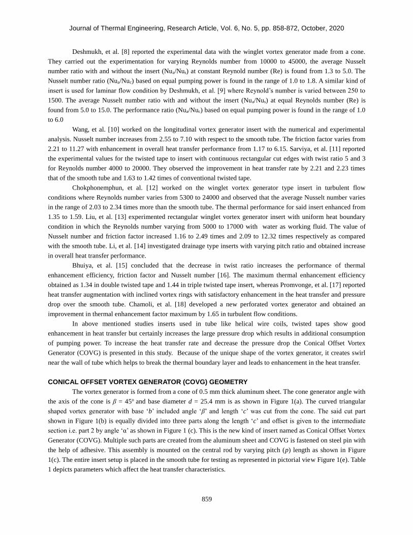
The vortex generator is formed from a cone of 0.5 mm thick aluminum sheet. The cone generator angle with
the axis of the cone is β = 45o and base diameter d = 25.4 mm is as shown in Figure 1(a). The curved triangular
shaped vortex generator with base ‘b’ included angle ‘β’ and length ‘c’ was cut from the cone. The said cut part
shown in Figure 1(b) is equally divided into three parts along the length ‘c’ and offset is given to the intermediate
section i.e. part 2 by angle ‘α’ as shown in Figure 1 (c). This is the new kind of insert named as Conical Offset Vortex
Generator (COVG). Multiple such parts are created from the aluminum sheet and COVG is fastened on steel pin with
the help of adhesive. This assembly is mounted on the central rod by varying pitch (p) length as shown in Figure
1(c). The entire insert setup is placed in the smooth tube for testing as represented in pictorial view Figure 1(e). Table
1 depicts parameters which affect the heat transfer characteristics.

Journal of Thermal Engineering, Research Article, Vol. 6, No. 5, pp. 858-872, October, 2020
860
(a)Vortex generator on cone (b) Conical offset vortex generator
(c) Conical offset vortex generator insert (d) Pictorial representation
of COVG
(e) Pictorial representation of conical offset vortex generator insert
Figure 1. Geometry details of vortex generator
The readings were taken for three different angles of attacks (α) with varying pitch length (p) as shown in
the Table 1. Among these three different angles of attacks, the best configuration was identified based on the higher
Nusselt number values.
Table 1. Parametric representation
The angle of attack for offset section ‘α’ 15° 15° 15° 30° 30° 30° 60° 60° 60°
p/d (pitch / diameter) 3.94 1.97 1.18 3.94 1.97 1.18 3.94 1.97 1.18

Journal of Thermal Engineering, Research Article, Vol. 6, No. 5, pp. 858-872, October, 2020
861
ANALYTICAL METHOD
Physical model
The Conical offset vortex generator insert model is inserted in the circular tube which is shown in Figure 1
(e). The computational domain has a test section of 1000 mm length (l) and diameter (d) 25.4 mm respectively.
Before experimentation, the numerical simulation was performed with COVG with varying pitch to diameter ratio
(p/d) 3.94, 1.97 and 1.18. Angle of attack varies from α = 15°, 30° and 60°. The simulation is performed under fully
developed flow condition. For every angle of attack all pitch to diameter ratio covered i.e. the simulation is carried
out for α = 15°, and range of p/d ratios as 3.94, 1.97 and 1.18, likewise all angle of attack are covered as mentioned
in Table 2.
Table 2. Assessed parameters in numerical study
Length of test
section ‘l’ (mm)
Diameter of smooth
tube ‘d’ (mm)
Pitch
(mm)
Pitch to diameter
ratio (p/d)
Angle of attack
(α)
1000 25.4 100, 50, 30 3.94, 1.97, 1.18 15°, 30°, 60°
Governing equations
For conduction of the numerical simulations following approximations are considered
Fluid flowing through the smooth tube is steady and incompressible
Heat loss due to thermal radiation into the surrounding is ignored
The air’s thermophysical properties are independent on temperature.
Based on these approximations the differential equations used to describe the flow of fluid and heat transfer
in smooth tube with COVG are established. Following equations are represented to show the flow field [12].
Continuity equation:
𝜕
𝜕𝑥𝑖= (𝜌𝑢1) = 0 (1)
Momentum equation:
𝜕(𝜌𝑢𝑖𝑢𝑗)
𝜕𝑥𝑗= −
𝜕𝜌
𝜕𝑥𝑖+
𝜕
𝜕𝑥𝑗{𝜇 (
𝜕𝑢𝑖
𝜕𝑥𝑗+
𝜕𝑢𝑗
𝜕𝑥𝑖)} −
2
3𝜇𝜕𝑢𝑘
𝜕𝑥𝑗𝜕𝑖𝑗 (2)
Energy equation:
𝜕
𝜕𝑥𝑖{(𝜌𝑢𝑖𝑐𝑝𝑇) − 𝑘
𝜕𝑇
𝜕𝑥𝑗} = 𝜇𝑗
𝜕𝑝
𝜕𝑥𝑗+ [𝜇 (
𝜕𝑢𝑖
𝜕𝑥𝑗+
𝜕𝑢𝑗
𝜕𝑥𝑖)] −
2
3𝜇𝜕𝑢𝑘
𝜕𝑥𝑘𝜕𝑖𝑗 (3)
The standard model 𝑘 − 𝜀turbulence [20] has been used. The turbulent kinetic energy (k) is calculated from
the same formula by claiming that the influence of the molecular viscosity of the fluid is insignificant, while the
turbulence dissipation frequency (𝜀) is estimated by using physical reasoning [19]. For the standard model, the
transport equations are given below. 𝜇𝑡is the dynamic viscosity of turbulence measured as
Journal of Thermal Engineering, Research Article, Vol. 6, No. 5, pp. 858-872, October, 2020
862
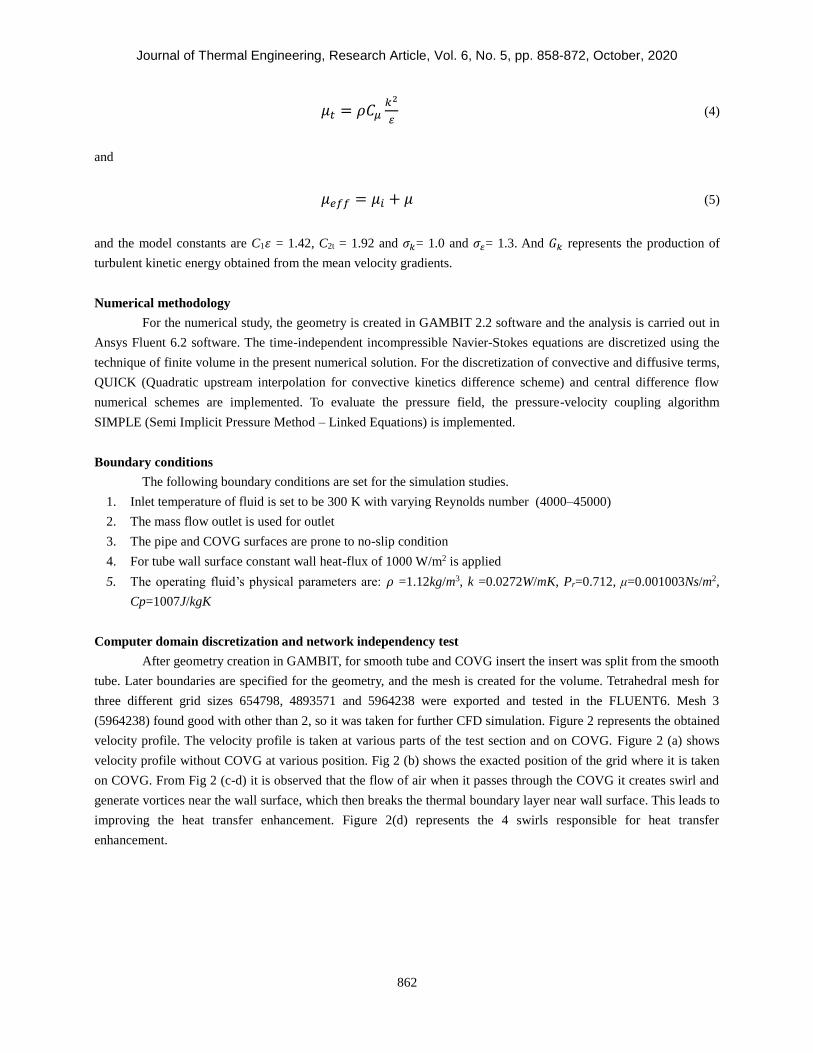
𝜇𝑡 = 𝜌𝐶𝜇𝑘2
𝜀 (4)
and
𝜇𝑒𝑓𝑓 = 𝜇𝑖 + 𝜇 (5)
and the model constants are C1𝜀 = 1.42, C2t = 1.92 and 𝜎𝑘= 1.0 and 𝜎𝜀= 1.3. And 𝐺𝑘 represents the production of
turbulent kinetic energy obtained from the mean velocity gradients.
Numerical methodology
For the numerical study, the geometry is created in GAMBIT 2.2 software and the analysis is carried out in
Ansys Fluent 6.2 software. The time-independent incompressible Navier-Stokes equations are discretized using the
technique of finite volume in the present numerical solution. For the discretization of convective and diffusive terms,
QUICK (Quadratic upstream interpolation for convective kinetics difference scheme) and central difference flow
numerical schemes are implemented. To evaluate the pressure field, the pressure-velocity coupling algorithm
SIMPLE (Semi Implicit Pressure Method – Linked Equations) is implemented.
Boundary conditions
The following boundary conditions are set for the simulation studies.
1. Inlet temperature of fluid is set to be 300 K with varying Reynolds number (4000–45000)
2. The mass flow outlet is used for outlet
3. The pipe and COVG surfaces are prone to no-slip condition
4. For tube wall surface constant wall heat-flux of 1000 W/m2 is applied
5. The operating fluid’s physical parameters are: 𝜌 =1.12kg/m3, k =0.0272W/mK, Pr=0.712, μ=0.001003Ns/m2,
Cp=1007J/kgK
Computer domain discretization and network independency test
After geometry creation in GAMBIT, for smooth tube and COVG insert the insert was split from the smooth
tube. Later boundaries are specified for the geometry, and the mesh is created for the volume. Tetrahedral mesh for
three different grid sizes 654798, 4893571 and 5964238 were exported and tested in the FLUENT6. Mesh 3
(5964238) found good with other than 2, so it was taken for further CFD simulation. Figure 2 represents the obtained
velocity profile. The velocity profile is taken at various parts of the test section and on COVG. Figure 2 (a) shows
velocity profile without COVG at various position. Fig 2 (b) shows the exacted position of the grid where it is taken
on COVG. From Fig 2 (c-d) it is observed that the flow of air when it passes through the COVG it creates swirl and
generate vortices near the wall surface, which then breaks the thermal boundary layer near wall surface. This leads to
improving the heat transfer enhancement. Figure 2(d) represents the 4 swirls responsible for heat transfer
enhancement.

Journal of Thermal Engineering, Research Article, Vol. 6, No. 5, pp. 858-872, October, 2020
863
(a) (b)
(c) (d)
Figure 2. Velocity vectors at different angles
EXPERIMENTAL METHOD
Schematic representation of the experimentation is represented in Figure 3.
Figure 3. Schematic representation of experimental Setup
Journal of Thermal Engineering, Research Article, Vol. 6, No. 5, pp. 858-872, October, 2020
864
The test section is made up of steel pipe having length 1000 mm, inner diameter is 25.4 mm, outer diameter
is 33.4 mm. To pass the air through test section a centrifugal air blower is installed at one end of the pipe. The
constant heat flux condition is obtained by wounding a heating coil on the test section. A dimmerstat is connected to
heating coil to control the voltage and constant heat flux situation was maintained. The fluid flow is measured by
differential pressure head with a manometer through a venturimeter. To prevent the heat loss, the test section is
insulated with rockwool insulation. For wall surface temperature measurement, at inlet of fluid flow and outlet of
fluid flow k-type thermocouples were installed. Fifteen k-type thermocouples were placed at equidistance, three were
placed at inlet and three were placed at outlet. All these thermocouples were placed 120° circumferentially apart. All
temperature readings were collected with calibrated data logger system. Average temperature is considered for
calculation. After the complete setup, the readings are taken, and data is collected by the following procedure.
Air is passed through the tube with the help of an air blower. The mass flow rate is adjusted by varying the
speed of air blower and it can be achieved with the help of dimmerstat which is attached to the air blower. An electric
current is passed through the electric coil to heat the test section. Every reading is taken after the system reaches its
steady state condition. The readings were taken for the inlet temperature and pressure, outlet temperature and
pressure and wall temperature.
Data Reduction
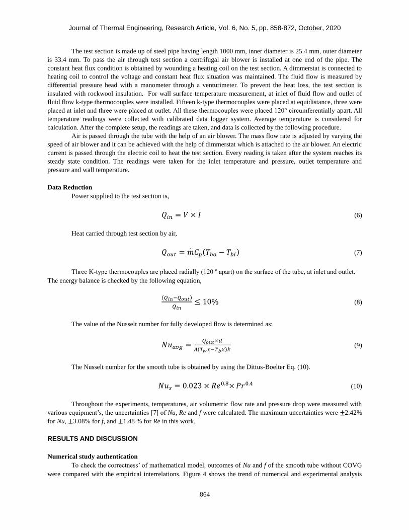
Power supplied to the test section is,
𝑄𝑖𝑛 = 𝑉 × 𝐼 (6)
Heat carried through test section by air,
𝑄𝑜𝑢𝑡 = 𝑚.𝐶𝑝(𝑇𝑏𝑜 − 𝑇𝑏𝑖) (7)
Three K-type thermocouples are placed radially (120 º apart) on the surface of the tube, at inlet and outlet.
The energy balance is checked by the following equation,
(𝑄𝑖𝑛−𝑄𝑜𝑢𝑡)
𝑄𝑖𝑛≤ 10% (8)
The value of the Nusselt number for fully developed flow is determined as:
𝑁𝑢𝑎𝑣𝑔 =𝑄𝑜𝑢𝑡×𝑑
𝐴(𝑇𝑤𝑥−𝑇𝑏𝑥)𝑘 (9)
The Nusselt number for the smooth tube is obtained by using the Dittus-Boelter Eq. (10).
𝑁𝑢𝑠 = 0.023 × 𝑅𝑒0.8×𝑃𝑟0.4 (10)
Throughout the experiments, temperatures, air volumetric flow rate and pressure drop were measured with
various equipment’s, the uncertainties [7] of Nu, Re and f were calculated. The maximum uncertainties were ±2.42%
for Nu, ±3.08% for f, and ±1.48 % for Re in this work.
RESULTS AND DISCUSSION
Numerical study authentication
To check the correctness’ of mathematical model, outcomes of Nu and f of the smooth tube without COVG
were compared with the empirical interrelations. Figure 4 shows the trend of numerical and experimental analysis

Journal of Thermal Engineering, Research Article, Vol. 6, No. 5, pp. 858-872, October, 2020
865
and depicts a close match. From Figure 4 it is seen that the results obtained from numerical analysis are better than
experimentation. The value of the Nusselt number is 7.4% and 4.2% for friction factor. Numerical simulation method
was also used to investigate all COVG inserts with different pitch to diameter ratios. Figure 5 shows the comparison
of numerical and experimental values of Nusselt number ratio (Nu/Nus) and friction factor ratio (f/fs) and the
maximum deviation are observed as 11.5% and 6.9% respectively which show the validation of numerical study with
experimental study.
Figure 4. Numerical confirmation of smooth tube for Nu and f
(a) (b)
Figure 5. The resemblance of the (a)Nu/ Nus and (b) f /fs for the tube fitted with vortex generator between numerical
simulation and experimentation.
Influence of angle of attack
To check the influence of the angle of attack ‘α’, it is numerically investigated for the different pitch to
diameter (p/d) ratio. All the obtained results are shown in Figure 6. Figure 6 (a) shows that Nusselt number
increasing with increase in Reynolds number. The angle of attack α=60º gives the maximum value of Nusselt number
i.e. 410 for pitch to diameter ratio 1.18. The variation of friction factor in comparison with Reynolds number is
represented in Figure 7(a). Figure 7 (a) shows exactly reverse trend with Nusselt number. The Friction factor
decreases with increase in Reynolds number. Figure 6 (b) and 7 (b) represents the relation between Nu/Nus and f/fs
versus Reynolds number.
0
0,01
0,02
0,03
0,04
0,05
0,06
0,07
0,08
0
20
40
60
80
100
120
140
160
180
0 10000 20000 30000 40000 50000
fNu
Re
Nu-Dittus Boelter
Nu-Numerical
f-Blasius
f-Numerical
Üs (Nu-Dittus Boelter)
Üs (Nu-Numerical)
Üs (f-Blasius)
Üs (f-Numerical)
0
1
2
3
4
5
6
7
8
0 10000 20000 30000 40000 50000
Nu/N
us
Re
Experimental
Numerical
0
10
20
30
40
50
60
70
80
0 10000 20000 30000 40000 50000
f/fs
Re
f/fs-Experimental
f/fs-Numerical

Journal of Thermal Engineering, Research Article, Vol. 6, No. 5, pp. 858-872, October, 2020
866
(a) (b)
Figure 6. Effect of the angle of attack over pitch to diameter ratio (a) Nu and (b) Nu/Nus
From the results obtained by numerical simulation, it is clear, the COVG with an angle of attack α=60º and
p/d = 1.18 gives better results, hence the same configuration insert is manufactured and tested with the said COVG
insert.
(a) (b)
Figure 7. Effect of the angle of attack on pitch to diameter ratio (a) f and (b) f/fs
0
50
100
150
200
250
300
350
400
450
0 10000 20000 30000 40000 50000
Nu
Re
p/d=3.94, α=15° p/d=3.94, α=30°p/d=3.94, α=60° p/d=1.97, α=15°p/d=1.97, α=30° p/d=1.97, α=60°p/d=1.18, α=15° p/d=1.18, α=30°p/d=1.18, α=60°
0
1
2
3
4
5
6
7
8
0 10000 20000 30000 40000 50000
Nu/N
us
Rep/d=3.94, α=15° p/d=3.94, α=30°p/d=3.94, α=60° p/d=1.97, α=15°p/d=1.97, α=30° p/d=1.97, α=60°p/d=1.18, α=15° p/d=1.18, α=30°p/d=1.18, α=60°
0
0,2
0,4
0,6
0,8
1
1,2
1,4
1,6
0 10000 20000 30000 40000 50000
f
Re
p/d=3.94, α=15° p/d=3.94, α=30°
p/d=3.94, α=60° p/d=1.97, α=15°
p/d=1.97, α=30° p/d=1.97, α=60°
p/d=1.18, α=15° p/d=1.18, α=30°
0
10
20
30
40
50
60
70
80
0 10000 20000 30000 40000 50000
f/fs
Rep/d=3.94, α=15° p/d=3.94, α=30°
p/d=3.94, α=60° p/d=1.97, α=15°
p/d=1.97, α=30° p/d=1.97, α=60°
p/d=1.18, α=15° p/d=1.18, α=30°
Journal of Thermal Engineering, Research Article, Vol. 6, No. 5, pp. 858-872, October, 2020
867
Validation for the experimental test set up
Authentication of Nu and f for a smooth tube is carried out experimentally along with the data analysis
techniques. Available empirical relationships are used to obtain the values of Nu and f observed in the current
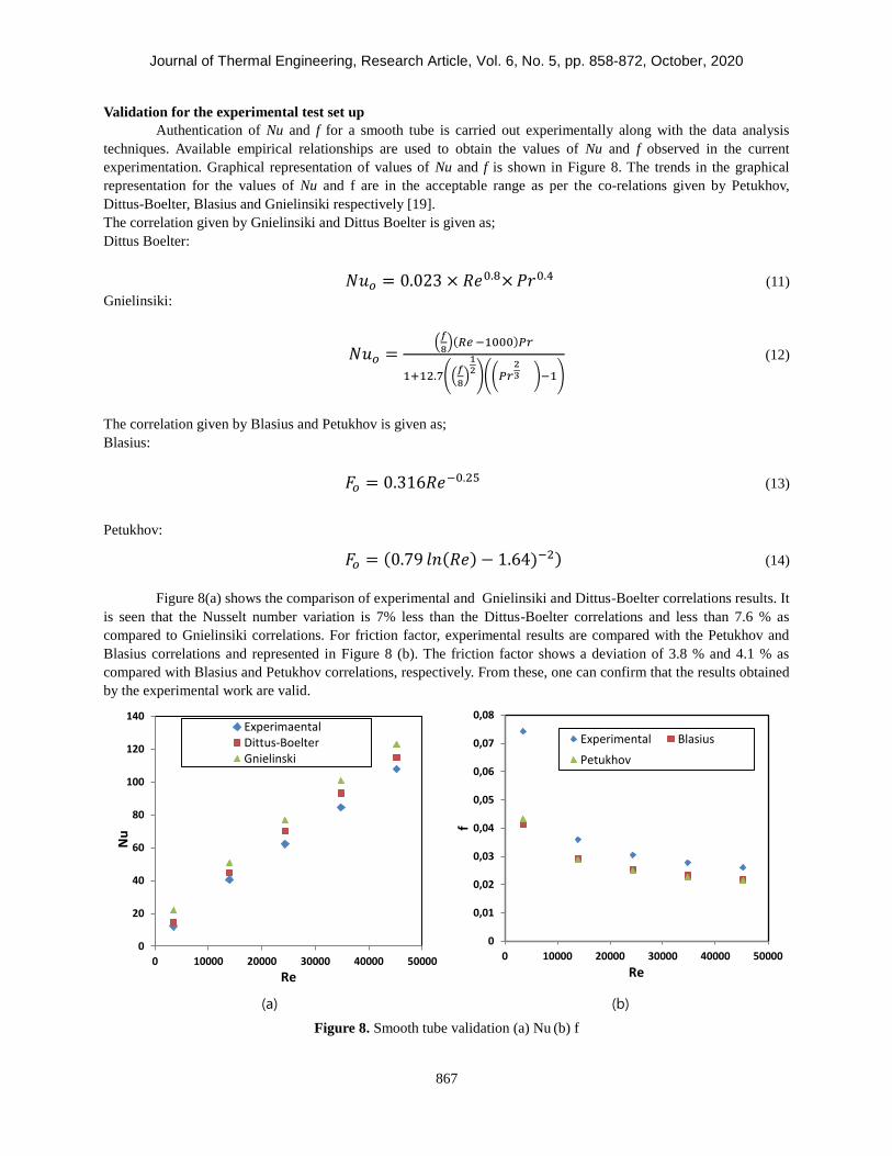
experimentation. Graphical representation of values of Nu and f is shown in Figure 8. The trends in the graphical
representation for the values of Nu and f are in the acceptable range as per the co-relations given by Petukhov,
Dittus-Boelter, Blasius and Gnielinsiki respectively [19].
The correlation given by Gnielinsiki and Dittus Boelter is given as;
Dittus Boelter:
𝑁𝑢𝑜 = 0.023 × 𝑅𝑒0.8×𝑃𝑟0.4 (11)
Gnielinsiki:
𝑁𝑢𝑜 =(𝑓
8)(𝑅𝑒 −1000)𝑃𝑟
1+12.7((𝑓
8)
12)((𝑃𝑟
23 )−1)
(12)
The correlation given by Blasius and Petukhov is given as;
Blasius:
𝐹𝑜 = 0.316𝑅𝑒−0.25 (13)
Petukhov:
𝐹𝑜 = (0.79 𝑙𝑛(𝑅𝑒) − 1.64)−2) (14)
Figure 8(a) shows the comparison of experimental and Gnielinsiki and Dittus-Boelter correlations results. It
is seen that the Nusselt number variation is 7% less than the Dittus-Boelter correlations and less than 7.6 % as
compared to Gnielinsiki correlations. For friction factor, experimental results are compared with the Petukhov and
Blasius correlations and represented in Figure 8 (b). The friction factor shows a deviation of 3.8 % and 4.1 % as
compared with Blasius and Petukhov correlations, respectively. From these, one can confirm that the results obtained
by the experimental work are valid.
(a) (b)
Figure 8. Smooth tube validation (a) Nu (b) f
0
20
40
60
80
100
120
140
0 10000 20000 30000 40000 50000
Nu
Re
ExperimaentalDittus-BoelterGnielinski
0
0,01
0,02
0,03
0,04
0,05
0,06
0,07
0,08
0 10000 20000 30000 40000 50000
f
Re
Experimental Blasius
Petukhov

Journal of Thermal Engineering, Research Article, Vol. 6, No. 5, pp. 858-872, October, 2020
868
Impact of pitch to diameter (p/d) ratio on Nu and Nu/Nus
(a) (b)
Figure 9. Variation of the Nu and Nu/Nus with Re for different pitch ratios: (a) Nu and (b) Nu/Nus
The experimental data is collected by performing more experiments to know the performance of pitch ratios
on angle α= 60°. The performance of convective heat transfer is shown in Figure 9(a) and (b). The variation of
Nusselt number with Re for angle of attack α = 60° to conical vortex generator and pitch to diameter ratio of 1.18 to
3.94 are shown in Figure 9 (a). Nusselt number increases with increase in Reynolds number. Figure 9(b) shows that
the Nusselt number (Nu/ Nus) ratio decreases as a result of an increase in the flow rate with an increase in Re. The
ratio of Nusselt number (Nu/Nus) for the COVG with p/d = 1.18 is found to be 2.59 to 6.8.
Effect of pitch to diameter ratio on f and f/fs
(a) (b)
Figure 10. Variation of the f and f/fs with Re for different pitch ratios: (a) f and (b) f/fs
The variation of friction factor and friction factor ratio f/fs with Re for the COVG variation in p/d and α= 60°
is shown in Figure 10 (a) and (b). Figure 10 (a) shows that the value of f decreases with an increase in Re. Figure 10
(b) shows value of f/fs increases with increase in the value of the Re.
0
50
100
150
200
250
300
350
400
0 10000 20000 30000 40000 50000
Nu
Re
Smooth Tube
p/d=3.94, α=60°
p/d=1.97, α=60°
p/d=1.18, α=60°
0
1
2
3
4
5
6
7
8
0 10000 20000 30000 40000 50000
Nu/N
us
Re
p/d=3.94, α=60°
p/d=1.97, α=60°
p/d=1.18, α=60°
0
0,2
0,4
0,6
0,8
1
1,2
1,4
1,6
1,8
2
0 10000 20000 30000 40000 50000
f
Re
p/d=3.94, α=60° p/d=1.97, α=60°
p/d=1.18, α=60°
0
10
20
30
40
50
60
70
80
90
0 10000 20000 30000 40000 50000
f/fs
Re
p/d=3.94, α=60° p/d=1.97, α=60°
p/d=1.18, α=60°

Journal of Thermal Engineering, Research Article, Vol. 6, No. 5, pp. 858-872, October, 2020
869
The experimental results obtained from newly proposed insert are then compared with the numerical data
which is represented in Figure 11. From Figure 11 it is observed that the variation in between experimental and
numerical results is within acceptable range i.e. 9.8% for Nu and 11.6 for f and shows in good agreement.
Figure 12 shows the comparison of ratio Nu/Nus obtained from the proposed vortex generator (COVG) with
some earlier smooth tube inserts found in the literature such as, wing vortex generator of Deshmukh, et al. [8],
perforated vortex generator of Chamoli et al. [18], turbulator of Nalavade, et al. [21]. The overall trend for various
types of inserts shows that the decreasing in Re the value of Nu/Nus increases. The proposed COVG insert shows the
higher values of Nu/Nus in the range of Re 3000 to 7000. The offset in the vortex generator interrupt the thermal
boundary layer and because of this the overall thermal performance increases. Hence the offset seems to be efficient
technique. For future work more geometric parameters of COVG can be studied to see the overall development in
thermo-hydraulic performance.
(a) (b)
Figure 11. Comparison of numerical simulation results with experimental results for (a) Nu and (b) f
Figure 12. Comparison of Nu/Nus of the present work vortex generator to earlier research
0
50
100
150
200
250
300
350
400
450
0 10000 20000 30000 40000 50000
Nu
Rep/d=3.94, α=60°- Experimental
p/d=1.97, α=60°- Experimental
p/d=1.18, α=60°- Experimental
p/d=3.94, α=60°- Numerical
p/d=1.97, α=60°- Numerical
0
0,2
0,4
0,6
0,8
1
1,2
1,4
1,6
1,8
0 10000 20000 30000 40000 50000
f
Rep/d=3.94, α=60°- Experimentalp/d=1.97, α=60°- Experimentalp/d=1.18, α=60°- Experimentalp/d=3.94, α=60°- Numericalp/d=1.97, α=60°- Numericalp/d=1.18, α=60°- Numerical
0
1
2
3
4
5
6
7
8
0 5000 10000 15000 20000 25000
Nu
/Nu
s
Re
Present Work
Deshmukh et al. [8]
Sunil Chamoli et al. [18]

Journal of Thermal Engineering, Research Article, Vol. 6, No. 5, pp. 858-872, October, 2020
870
CONCLUSIONS
In this paper, the effect of the vortex generator fitted in smooth tube on fluid flow and heat transfer is
studied numerically and experimentally. The numerical simulation tests were conducted to find the optimum
geometry of COVG. Multiple tests were carried out with pitch to diameter ratio (p/d = 1.18, 1.97, 3.94) and angle of
attack (α = 15°, 30°, 60°). The best results obtained for angle of attack (α = 60°), it creates more swirl and disturb the
boundary layer near wall surface. The same COVG is manufactured for experimentation and tests were conducted to
see the effect of heat transfer. Looking at the numerical and experimental results following conclusions are drawn;
1. As value of pitch to diameter ration (p/d) decreases, the value of Nu and f increases.
2. The numerical study shows that the COVG with angle of attack (α = 60°) shows better results than (α = 15°
and 30°) for Reynolds number in the range of 4000 to 50000.
3. The experimental study performed using COVG as insert with pitch to diameter ratio (p/d = 1.18) and angle
of attack (α = 60°) shows enhancement in heat transfer rate from 2.3 to 6.09 times more than the smooth
tube.
ACKNOWLEDGMENT
The author acknowledges the fund received (Research Grant Letter Ref. No. OSD/BCUD/392/202, Dated-
11/11/2016) from BCUD, Savitribai Phule Pune University, Pune, support received from the Pune Institute of
Computer Technology, Pune and encouragement received from the Department of Mechanical Engineering, Dr. D. Y.
Patil Institute of Technology, Pimpri, Pune for carrying out this research work.
CONFLICT OF INTEREST
The authors declare that there is no conflict of interests regarding the publication of this paper.
NOMENCLATURE
Symbol Meaning
A Test section inside surface area (m2)
d Inside diameter of test section (m)
b Base of vortex generator (Refer Figure 1 a) (m)
c Vortex generator length (Refer Figure 1 a) (m)
p Pitch of vortex generator (Refer Figure 1 c) (m)
l Length of test section (m)
k Thermal conductivity (W/mK)
m Mass flow rate of fluid (kg/s)
T Temperature (K)
V Voltage (V)
I Current (A)
Cp Specific heat at constant pressure (J/kg K)
Greek Symbols
α Angle of attack (Refer Figure 1 c)
β Included angle for vortex generator (Refer Figure 1 a)
µ Dynamic Viscosity (N-s/m2)
ν Kinematic Viscosity (m2/s)
Subscripts
a Augmented case
c Equivalent smooth tube at constant pumping power and constant surface

Journal of Thermal Engineering, Research Article, Vol. 6, No. 5, pp. 858-872, October, 2020
871
i Inlet
o Outlet
s Smooth tube
w Wall
Dimensionless parameters
Re Reynolds number, 𝜌𝜈𝑑
𝜇
Pr Prandtl number, 𝜇𝐶𝑝
𝑘
f Friction factor
Nu Nusselt number
p/d Ration of pitch to inner diameter
REFERENCES
[1] Kakac S, Bergles AE, Mayinger F, Yüncü H. Heat Transfer Enhancement of Heat Exchanger. Kluwer
Academic Publishers Ed.1 TJ263.H425, 1999.
[2] Webb RL, Hyun KN. Principles of Enhanced Heat Transfer. Taylor & Francis Group Ed.2 TJ260.W36, 2005.
[3] Dewan A, Mahanta P, Sumithra K. Suresh P. Review of passive heat transfer augmentation techniques. Part
A: Journal of Power and Energy 2004;509–27.
[4] Liu S, Sakr M. A comprehensive review on passive heat transfer enhancements in pipe exchangers.
Renewable and Sustainable Energy Reviews 2013;19:64-81.
[5] Anderson, JD. Computational Fluid Dynamics-The Basics with Applications. McGraw Hill Publication,
Sixth Reprint, 2014.
[6] Fakiri F, Rahmoun K. Unsteady numerical simulation of turbulent forced convection in a rectangular pipe
provided with waved porous baffles. Journal of Thermal Engineering 2017;3(5):1466-1477.
[7] Singh SK, Kumar M, Kumar A, Gautam A, Chamoli S. Thermal and friction characteristics of a circular tube
fitted with perforated hollow circular cylinder inserts. Applied Thermal Engineering 2018;130:230-241.
[8] Deshmukh PW, Vedula RP. Heat transfer and friction factor characteristics of turbulent flow through a
circular tube fitted with vortex generator inserts. International Journal of Heat and Mass Transfer
2014;79:551–560.
[9] Deshmukh PW, Prabhu SV, Vedula RP. Heat transfer enhancement for laminar flow in tubes using curved
delta wing vortex generator. Applied Thermal Engineering 2016;106:1415-1426.
[10] Wang Y, Liu P, Shan F, Liu Z, Liu W. Effect of longitudinal vortex generator on the heat transfer
enhancement of a circular tube. Applied Thermal Engineering 2019;148:1018-1028.
[11] Sarviya RM, Fuskele V. Heat transfer and pressure drop in a circular tube fitted with twisted tape insert
having continuous cut edges. Journal of Energy Storage 2018;19:10-14.
[12] Chokphoemphun S, Pimsarn M, Thianpong C, Promvonge P. Heat transfer augmentation in circular tube
with winglet vortex generators. Chinese Journal of Chemical Engineering 2015;23(4):605-614.
[13] Liu H, Li H, He Y, Chen Z. Heat transfer and flow characteristics in a circular tube fitted with rectangular
winglet vortex generators. International Journal of Heat and Mass Transfer 2018;126:989-1006.
[14] Li P, Liu P, Liu Z, Liu W. Experimental and numerical study on the heat transfer and flow performance for
the circular tube fitted with drainage inserts. International Journal of Heat and Mass Transfer 2017;107:686-
696.
[15] Bhuiya MMK, Chowdhury MSU, Shahabuddin M, Saha M, Memon LA. Thermal characteristics in a heat
exchanger tube fitted with triple twisted tape inserts. International Communications in Heat and Mass
Transfer 2013;47:124-132.
Journal of Thermal Engineering, Research Article, Vol. 6, No. 5, pp. 858-872, October, 2020
872
[16] Bhuiya MMK, Sayem ASM, Islam M, Chowdhury MSU, Shahabuddin M. Performance assessment in a heat
exchanger tube fitted with double counter twisted tape inserts. International Communications in Heat and
Mass Transfer 2014;50:25-33.
[17] Promvonge P, Koolnapadol N, Pimsarn M, Thianpong C, Thermal performance enhancement in a heat
exchanger tube fitted with inclined vortex rings. Applied Thermal Engineering 2014;62:285-292.
[18] Chamoli S, Lu R, Yu P, Thermal characteristic of a turbulent flow through a circular tube fitted with
perforated vortex generator inserts. Applied Thermal Engineering 2017;121:1117-1134.
[19] Incropera FP, Witt PD, Bergman TL, Lavine AS, Fundamentals of Heat and Mass Transfer. John-Wiley &
Sons, 2006.
[20] Launder BE, Spaldling DB, Lectures Notes in Mathematical Models of Turbulence. Academic Press,
London, 1972.
[21] Nalavade SP, Prabhune CL, Sane NK, Effect of novel flow divider type turbulator on fluid flow and heat
transfer. Thermal Science and Engineering Progress 2019;9:322-331.