advance guardrail assembly guide … guardrail assembly guide eiger 500 agr - single width this...
TRANSCRIPT

ADVANCE GUARDRAIL ASSEMBLY GUIDE EIGER 500 AGR - SINGLE WIDTHThis assembly guide is designed to provide you with step by step instructions to ensure your system is erected easily and safely. Before assembly please read the safety notes carefully. Eiger 500 is a mobile access tower system complying with EN 1004:2004 and WAHR, with vertical ladder access, designed for Clas
DESCRIPTION
The Eiger 500 Access Tower gives a work platform for use by up to two persons, with weight evenly distributed across the platform.
The information and instructions included in this manual are provided to help get the best possible service from your Eiger 500 Access Tower. To ensure that the tower is used safely and responsibly, we strongly recommend that these instructions are read by everyone involved in its erection and use prior to assembling and using the tower, and that the recommendations are followed at all times.
SAFETY
Before using this access tower and to avoid personal injury, carefully read and understand these instructions. If there is anything you do not understand, DO NOT use this access tower, contact the supplier for advice.
Make sure you are aware of all safety requirements and that this access tower is suitable for the task you wish to undertake. The work area must be cordoned off to create a safe zone from the general public and bystanders. The safe zone must be a minimum of 3m radius or 1m greater than the platform height being used.
This access tower must not be set up, used, moved or dismantled by persons who are under the influence of alcohol or drugs. Do not use this access tower if you are tired or unwell. This access tower must only be used by persons who are medically fit to do so. If you have any medical condition, are recovering from any medical condition or suffer from any mental or physical disability, you MUST seek professional medical advice before using this access tower.
The persons assembling this tower must be competent and qualified to do so.
WEIGHTS
The tower itself, regardless of size, has a maximum total Safe Working Load (SWL) of 950Kg. This is the maximum load that can be placed on the castors. When checking the SWL for your tower, you must firstly deduct the towers self weight from its overall SWL to give you the maximum payload (user plus tools and materials). You must also ensure that a platforms SWL is not exceeded.
Do not overload the platform(s) beyond the stated weight loading. Single platform up to 275Kg evenly distributed or 550Kg when used as a pair. The maximum number of working platforms per tower must not exceed two.
Wear the correct Personal Protective Equipment (PPE) for the task you are performing.
Wear gloves when handling tower components.
Wear suitable clothing. Steel toecap boots or shoes must be worn. If appropriate, wear a hard hat. Do not wear loose jewellery or clothing that may get in the way or become trapped in the access tower. Tie back long hair.
The tower must not be used in adverse weather conditions ie: heavy rain, snow or ice. If the tower becomes contaminated by paints, chemicals or similar materials, the tower must not be used until such contaminates have been completely removed.
You MUST perform a risk assessment before using this access tower to ensure your safety and the safety of others. Do not use this access tower where there are overhead power lines or similar hazards within your reach and that of the tower.
If leaving an erected tower unattended you must block access to the tower by unauthorised persons. Use suitable mesh fencing or boarding to make access impossible. If you cannot block access, the tower MUST be dismantled. Do not suspend the tower from another structure.
1
2
3
4
5
6
7
8
9
10
11
HATCH PLATFORM
AGR PANEL
4 RUNG FRAME
DIAGONAL BRACE
2 RUNG FRAME
HORIZONTAL BRACE
STABILISER
ADJUSTABLE LEG & CASTOR
2 RUNG LADDER FRAME
4 RUNG LADDER FRAME
TOEBOARD SET
+44 (0)1244 833 933 [email protected] popupproducts.co.uk
SAFETY CONT.Only carry tools and materials with you when ascending or descending the tower if they are safely retained in a tool belt and do not restrict your free movement. Tools / materials may be hoisted to the deck via a rope. PROPERLY ASSESS THE RISK METHOD!
Do not lean from the tower and never apply undue side force. Maximum permitted side load must not exceed 20Kg (200N). Never use boxes, steps or similar items to gain additional height. Do not stand on the toeboards, horizontal or diagonal braces. Always use the towers built in ladders to access platforms and climb from inside the tower NEVER from outside. When climbing, always keep your feet in the middle of the rungs and grip the upper rungs with your hands NEVER the sides.
When winds exceed Beaufort force 4, cease to use the tower. Always be aware that using the tower in situations such as unclad or open ended buildings or on the corners of buildings could cause additional wind loading of the tower structure.
Wind Speeds
Force Peak MPH
Peak KPH Guidance
4
6
8
18
31
46
29
50
74
Moderate breeze - raises dust and loose paper
Strong breeze - difficult to use umbrella
Gale force - walking is difficult
PREPARATIONClear the floor area of all obstacles and debris. Where possible sweep the floor. Check the ground upon which the tower is to be used is capable of supporting the combined weight of the tower and any necessary loading. The ground should be level and any slope should be within the scope of the adjustable legs. Ensure all tools and equipment required to erect the tower are available and on site.
Check each component for condition and correct operation BEFORE you start assembling the tower. Any faulty or damaged items MUST be replaced before assembling the tower. As you inspect each part, segregate types to make the task easier.
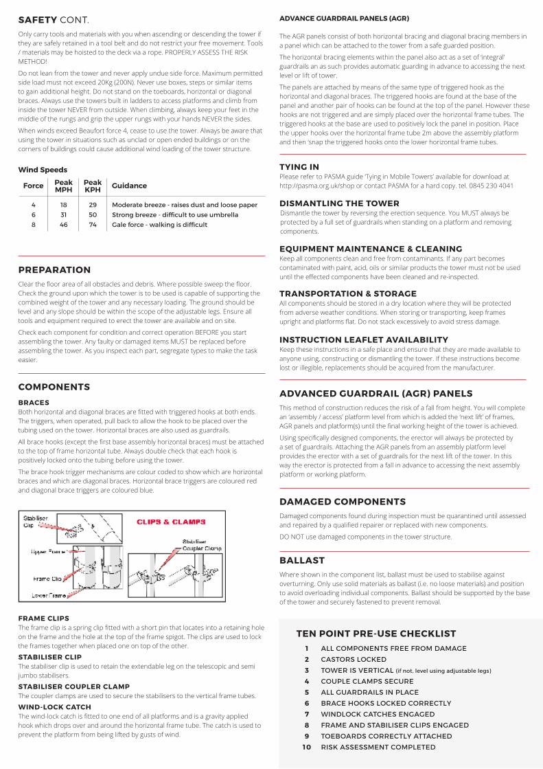
COMPONENTS
BRACESBoth horizontal and diagonal braces are fitted with triggered hooks at both ends. The triggers, when operated, pull back to allow the hook to be placed over the tubing used on the tower. Horizontal braces are also used as guardrails.
All brace hooks (except the first base assembly horizontal braces) must be attached to the top of frame horizontal tube. Always double check that each hook is positively locked onto the tubing before using the tower.
The brace hook trigger mechanisms are colour coded to show which are horizontal braces and which are diagonal braces. Horizontal brace triggers are coloured red and diagonal brace triggers are coloured blue.
FRAME CLIPSThe frame clip is a spring clip fitted with a short pin that locates into a retaining hole on the frame and the hole at the top of the frame spigot. The clips are used to lock the frames together when placed one on top of the other.
STABILISER CLIPThe stabiliser clip is used to retain the extendable leg on the telescopic and semi jumbo stabilisers.
STABILISER COUPLER CLAMPThe coupler clamps are used to secure the stabilisers to the vertical frame tubes.
WIND-LOCK CATCHThe wind-lock catch is fitted to one end of all platforms and is a gravity applied hook which drops over and around the horizontal frame tube. The catch is used to prevent the platform from being lifted by gusts of wind.
DAMAGED COMPONENTSDamaged components found during inspection must be quarantined until assessed and repaired by a qualified repairer or replaced with new components.
DO NOT use damaged components in the tower structure.
BALLASTWhere shown in the component list, ballast must be used to stabilise against overturning. Only use solid materials as ballast (i.e. no loose materials) and position to avoid overloading individual components. Ballast should be supported by the base of the tower and securely fastened to prevent removal.
1
2
3
4
5
6
7
8
9
10
ALL COMPONENTS FREE FROM DAMAGE
CASTORS LOCKED
TOWER IS VERTICAL (if not, level using adjustable legs)
COUPLE CLAMPS SECURE
ALL GUARDRAILS IN PLACE
BRACE HOOKS LOCKED CORRECTLY
WINDLOCK CATCHES ENGAGED
FRAME AND STABILISER CLIPS ENGAGED
TOEBOARDS CORRECTLY ATTACHED
RISK ASSESSMENT COMPLETED
TEN POINT PRE-USE CHECKLIST
ADVANCE GUARDRAIL PANELS (AGR)
The AGR panels consist of both horizontal bracing and diagonal bracing members in a panel which can be attached to the tower from a safe guarded position.
The horizontal bracing elements within the panel also act as a set of ‘integral’ guardrails an as such provides automatic guarding in advance to accessing the next level or lift of tower.
The panels are attached by means of the same type of triggered hook as the horizontal and diagonal braces. The triggered hooks are found at the base of the panel and another pair of hooks can be found at the top of the panel. However these hooks are not triggered and are simply placed over the horizontal frame tubes. The triggered hooks at the base are used to positively lock the panel in position. Place the upper hooks over the horizontal frame tube 2m above the assembly platform and then ‘snap the triggered hooks onto the lower horizontal frame tubes.
ADVANCED GUARDRAIL (AGR) PANELSThis method of construction reduces the risk of a fall from height. You will complete an ‘assembly / access’ platform level from which is added the ‘next lift’ of frames, AGR panels and platform(s) until the final working height of the tower is achieved.
Using specifically designed components, the erector will always be protected by a set of guardrails. Attaching the AGR panels from an assembly platform level provides the erector with a set of guardrails for the next lift of the tower. In this way the erector is protected from a fall in advance to accessing the next assembly platform or working platform.
TYING INPlease refer to PASMA guide ‘Tying in Mobile Towers’ available for download at http://pasma.org.uk/shop or contact PASMA for a hard copy. tel. 0845 230 4041
DISMANTLING THE TOWERDismantle the tower by reversing the erection sequence. You MUST always be protected by a full set of guardrails when standing on a platform and removing components.
EQUIPMENT MAINTENANCE & CLEANINGKeep all components clean and free from contaminants. If any part becomes contaminated with paint, acid, oils or similar products the tower must not be used until the effected components have been cleaned and re-inspected.
TRANSPORTATION & STORAGEAll components should be stored in a dry location where they will be protected from adverse weather conditions. When storing or transporting, keep frames upright and platforms flat. Do not stack excessively to avoid stress damage.
INSTRUCTION LEAFLET AVAILABILITYKeep these instructions in a safe place and ensure that they are made available to anyone using, constructing or dismantling the tower. If these instructions become lost or illegible, replacements should be acquired from the manufacturer.

MOVING A TOWERIf you need to move the tower to a new location or a new level, fully dismantle it an rebuild it at the new location.
If moving the tower a small distance, remove all personnel, materials, tools and everything else from the tower.
If the stabilisers can remain in position, reduce the tower to a platform height of 4m before moving. Raise the stabiliser’s legs so that the footpads are approximately 25mm off the ground.
If the stabilisers need to be removed or repositioned (i.e. swung in to allow access to a doorway) you must reduce the tower to a platform height of 2m. With help, unlock all castors, move the tower, then re-lock the castors and vertically align the tower using the adjustable legs ready for rebuilding to the required height.
The tower should only be moved by manual effort and only by pushing the base.
STABILISERSStabilisers shall always be fitted where specified, these increase the stability as a free standing structure. Best effect is obtained from the stabilisers when they are arranged in a footprint as near to a square (see fig. 1).
When using the tower against a wall, they may be positioned in fig.2, but the wall must be at least two thirds the height of the top working platform. When locating stabilisers on the towers, maximum stability will be achieved by positioning at an angle of 45 degrees. Extend the leg to achieve maximum leg extension and ensure that the top coupler is positioned underneath the nearest horizontal frame tube.
Securely lock the top coupler before attaching the lower arm to the fvertical frame tube. Ensure that the rubber foot pad is in contact with the ground and that the ground can support the weight of the tower and stabilisers.
GETTING STARTEDThe Eiger 500 tower is available in two base sizes, 850mm by a 1.8m or 2.5m platform length. The tower will be supplied with various height frames and you must always start with the smallest size frames first. The following instructions deal with a tower using 2 rung frames at the start, if supplied with 3 rung frames instead of 2 rung, start with the 3 rung frames.
Where you have both 2 rung and 3 rung, you must use the 2 rung first and the 3 rung next, with (where applicable) 4 rung frames at the top. The first platform needs to be carefully positioned to ensure that the remaining tower is constructed safely, use the chart below to find the exact position for the platform height you are erecting.
The access tower requires a minimum of two persons to assemble it, do not attempt to assemble the tower on your own.
Never stand on an un-guardrailed platform above the first rung of a tower. If your risk assessment shows it necessary, you may also need to guardrail platforms at this level.
EIGER 500 AGR ASSEMBLY GUIDESINGLE WIDTH 850 TOWER 4.2M PLATFORM HEIGHT
4.7
5.2
5.7
6.2
6.7
7.2
7.7
8.2
8.7
9.2
9.7
10.2
10.7
11.2
11.7
12.2
PLATFORM REPOSITIONING TABLE
1
2
3
4
1
2
3
4
1
2
3
4
1
2
3
4
5
6
7
8
5
6
7
8
5
6
7
8
5
6
7
8
9
10
11
12
9
10
11
12
9
10
11
12
9
10
11
12
13
14
15
16
13
14
15
16
13
14
15
16
17
18
19
20
17
18
19
20
21
22
23
24
Tower Platform
Height
Swap Platform
(Rung)
Platform 1 (Rung)
Platform 2 (Rung)
Platform 3 (Rung)
Platform 4 (Rung)
Platform 5 (Rung)
BUILD PROCESS
STEP 1Insert castor / adjustable leg assemblies into base of 2 rung frame and one 2 rung frame, allowing approximately 75mm of extended leg for levelling.
Press down firmly on the braking mechanism to lock the castors.
STEP 2Fit a horizontal brace onto the vertical frame tube of the 2 rung frame, resting on the horizontal tube of the first rung of the frame. Ensure the brace trigger faces to the outside of the tower.
STEP 3Join the second 2 rung frame to the first ensuring brace hook again rests on the first rung of the frame. Fit the second horizontal brace as shown with hook trigger facing downwards. Level around base of tower using spirit level, making adjustments as necessary to adjustable legs until the frames have an inclination no more than 1% from the vertical.
STEP 4Locate 4 rung frames and fit diagonal brace onto first rung on one frame and third rung on the other frame. Position the hook to one side of the ladder section in the ladder frame as shown.
STEP 5Locate AGR panels on frames. Position top hooks of AGR panels on horizontal tubes of the sixth rung of the frames before attempting to locate the triggered hooks.
Ensure lower hooks are positively locked onto the horizontal rungs and the AGR panels are vertical and parallel to each other.

BUILD PROCESS CONT.
STEP 6Locate platform on fourth rungs ensuring hatch opening is at the ladder section end of the tower.
STEP 7Attach stabilisers at base of tower. Please refer to the ‘Stabilisers’ section for details on achieving an optimum stabiliser footprint.
STEP 8Locate next set of 4 rung frames.
STEP 9Locate next set of AGR panels. Position top hooks of AGR panels on horizontal tubes of the frames before attempting to locate the triggered hooks.
Ensure lower hooks are positively locked onto the horizontal rungs and the AGR panels are vertical and parallel to each other.
STEP 10Locate hatch platform to the eighth rungs of the frames.
NOTE: If building the tower beyond the 4.20m level, continue with steps 8,9 & 10 until the desired height is achieved, then follow step 11.
STEP 11Fit the toeboard set ensuring the edges of the toeboard overlap the platform edges on all four edges.