adiabatic cooling installation & operation manual system (acs) · addresses a hazardous...
TRANSCRIPT

Adiabatic Cooling System (ACS)
Inst
alla
tion
& Op
erat
ion
Man
ual
With ™ technology

32
The Güntner Adiabatic Cooling System with hydroBLU™ technology is an advanced system which can be incorporated within the design and construction of Güntner’s air cooled condensers GVD/GVW and dry coolers (fluid coolers) GFD/GFW either at the time of purchase or at a later stage as a retrofit.
Güntner’s product portfolio for heat rejection equipment presents to the end user a choice from fully dry to fully wet solution system. Energy efficiency and utility costs, associated with the system design, challenge the end user with a variety of possible solutions for the heat rejection equipment being selected. Specific job site location and the relevant utility costs will ultimately be the deciding factor when selecting the optimum equipment for each project.
When an Adiabatic Cooling System with hydroBLU™ technology is selected, it is essential to comply with the following guidelines. This manual shall be read in its entirety prior to the start-up of the equipment. This manual will form the basis for implementing a maintenance program specific to the location and the anticipated run hours of the hydroBLU™ Adiabatic Cooling System in order to promote safe, efficient and longstanding operation.
Table of Contents1. Safety Information .................................................................. 4
1.1 Safety Symbols ................................................................................. 41.2 Safety Instructions ............................................................................. 41.3 Refrigerant/Fluid Safety .................................................................... 5
2. General Information ................................................................ 62.1 Warranty Statement .......................................................................... 6
3. Receiving and Inspection ......................................................... 8
4. Rigging ................................................................................. 94.1 Pre-Rigging Inspection ....................................................................... 94.2 Rigging and Installation ..................................................................... 9
5. Start–Up ............................................................................... 105.1 System Inspection ............................................................................. 105.2 Preliminary Operation Mode ............................................................... 115.3 Operation Mode ................................................................................ 14
6. Prolongued Shut Down ............................................................ 15
7. hydroBLU™ System Operation ................................................. 18
8. Water Quality Guidelines ......................................................... 20
9. Cooling Pad Media Guidelines .................................................. 21
10. Cooling Pad Media Maintenance ............................................. 21
11. Maintenance ........................................................................ 22
12. Adiabatic Cooling System Controls ......................................... 2212.1 Guntner Hydro Management (GHM) .................................................. 2212.2 Dry Mode ....................................................................................... 2312.3 GHM Water Saving Mode ................................................................. 2312.4 GHM Manual Mode ......................................................................... 23 12.4.1 Manual Mode ON / OFF ........................................................ 2412.5 Adjusting Settings on the GHM ......................................................... 2512.6 Edit Mode ...................................................................................... 26
Adiabatic Cooling System (ACS)With ™ technology

54
1. Safety Information1.1 Safety Symbols
1.2 Safety Instructions• Installation and maintenance must only be carried out by qualified
personnel who are familiar with this type of equipment.
• Always wear safety glasses, gloves and head protection when working
on the equipment.
• Avoid contact with sharp edges and exposed finned surfaces as these
can cause painful lacerations.
• All units must be properly evacuated prior to charging the system.
• Ensure all power sources are disconnected prior to any service work
being done on the units.
• Never apply heat to a sealed refrigeration system.
• Keep hands away from fans when the unit is running.
• Ensure all mounting bolts are tight and are the correct length for the
specific application.
• Maintain all safety labels on the unit in good condition: If required
replace with new.
DANGER !
Addresses a hazardous situation which, if encountered, will result in death or serious injury.
Addresses a hazardous situation which, if encountered, might result in death or serious injury.
Addresses a hazardous situation which, if encountered, could result in minor or moderate injury.
Indicates instructions that pertain to safe equipment operation. Failure to comply with these instructions could result in damage to the equipment.
1.3 Refrigerant/Fluid Safety
Anhydrous Ammonia (NH3): Specific precaution must be adhered to when people are working with or are exposed to Anhydrous Ammonia.
Ammonia is considered a high health hazard because it is corrosive to the skin, eyes and lungs. Exposure to 300 parts per million (ppm) is life threatening. Ammonia is also flammable at concentrations of approximately 15% to 28% by volume in air. When mixed with lubricating oils, its flammable concentration range is increased. It can explode if released in an enclosed space with a source of ignition present or if a vessel containing anhydrous ammonia is exposed to fire.
Personal protective equipment must be worn at all times when working with Ammonia. For systems that have an operating charge greater than 10,000 lbs a process safety management program is mandatory. More information on this topic is available from OSHA.
Failure to follow this warning may result in personal injury or death.
Although halocarbon refrigerants are classified as safe refrigerants; certain precautions must be observed when handling them. Refrigerant can be harmful if inhaled. When released to the atmosphere in the liquid state refrigerants evaporate rapidly freezing anything they contact. Refrigerants must be used and recovered responsibly.
Failure to follow this warning may result in personal injury or death.
DANGER!
WARNING!
CAUTION!
NOTICE
WARNING !

76
2. General Information
Güntner Adiabatic Condensers and Drycoolers are designed to provide optimum efficiency and an extended life when properly installed, operated and maintained. It is therefore highly recommended that a comprehensive maintenance schedule be developed and undertaken on a regular pre-determined basis. This manual will assist in developing such a schedule.
This equipment is relatively complicated and the installation, operation, maintenance and servicing should only be carried out by suitable individuals who are qualified to carry out these functions. These individuals shall also be familiar with and comply with all applicable governmental standards and regulations pertaining to these functions.
2.1 Warranty Statement
Guntner U.S. LLC (“Güntner”) warrants the product to be free from defects in workmanship and materials under normal usage for a period of 24 months from the date of purchase (the “Warranty Period”), provided that the product is correctly installed and operated within the recommended limits of Güntner’s technical documentation. This warranty is only valid if the product is given normal and proper use and complies with Güntner‘s installation and maintenance instructions. Güntner assumes no responsibility for repairs to a product sustaining damages resulting from user modifications, attachments to the product, misuse, alteration or negligent use.
Güntner, at its option, shall repair or replace, free of charge to the buyer, all components of the product which are or become defective during the Warranty Period as a result of defects in design, workmanship or materials; ordinary wear and tear excluded; provided however, that:
• The product is applied correctly.
• All operating and installation instructions for the product are complied with.
• System component and piping design is in accordance with state of the art HVAC practice.
• Nitrogen, or an inert gas, is introduced into the piping during the brazing of the piping installation.
In all instances, industry standard refrigeration practices must be observed and utilized by certified refrigeration technicians, mechanics, pipe fitters, design engineers, etc. when installing and servicing Güntner products. This warranty shall not include ordinary maintenance or cleaning of the product, defects in the installation of the product, or defects in turning and moving parts. This warranty also does not cover physical damage to the product during transit; or otherwise, after purchase of the product but before installation.
The buyer must request repair or replacement of the defective component through a written notice delivered to Güntner no later than two business days after the buyer becomes aware of the defect and the buyer must provide Güntner with the time and opportunity to make such repair or replacement. Otherwise, Güntner will be released from liability for the defect. Under no circumstances will Güntner make any repair or replacement without Güntner’s prior written consent; except to the limited extent permitted by Güntner’s Service Policy.
Any transport and exchange costs for the repair or replacement shall be borne by the buyer. Güntner shall also not be liable for costs incurred in dismantling or fitting replacement parts or for any independent inspection undertaken by the buyer. The buyer shall return any allegedly defective goods, postage or freight paid to Güntner at the address below. Upon receipt of the goods and inspection thereof, Güntner shall repair or replace, at Güntner’s discretion, the defective components and shall return the same to the buyer, return postage and freight paid. This shall constitute full compliance with Güntner’s warranty obligations hereunder. Güntner accepts no liability for the direct or indirect consequences of any modifications of or repairs to the product made by the buyer or by a third party without the prior consent of Güntner. Güntner reserves the right to inspect the product for customer abuse during the warranty period if abnormal claims against the equipment should arise.This warranty shall not apply to Güntner products which have been improperly installed or repaired; or altered in any way, outside of the manufacturer’s factory; or have been subject to misuse, negligence or accident. Equipment or component parts such as valves, electric motors, electric heaters, and electric accessories manufactured by others and used as part of or in connection with Güntner products, carry only the warranty of the manufacturer thereof. This warranty shall be void if equipment has been
WARNING!
NOTICEThe type of refrigerant must comply with what is indicated on the submittal drawings and/or the unit’s nameplate. Design operating pressures, as indicated on the nameplate, must never be exceeded!
NOTICEAdiabatic drycoolers and all piping systems must be correctly evacuated prior to charging the system with refrigerant to ensure the complete removal of moisture and non–condensables from the entire refrigerant circuit.
Failure to comply with any of these requirements could result in serious damage to the equipment and/or the property where it is installed as well as personal injury and/or death to themselves and/or people at the specific location.
98
subjected to negligence, abuse, misuse, low voltage, corrosive chemicals, excessive pressure, accident, outward damage, or hidden damage while in transit, or if operated contrary to the manufacturer’s recommendations.
THIS WARRANTY APPLIES ONLY TO THE REPAIR OR REPLACEMENT OF THE PRODUCT AND/OR ITS COMPONENTS AND EXPRESSLY EXCLUDES RESPONSIBILITY FOR DAMAGES NOT OCCURRING TO THE PRODUCT AND/OR ITS COMPONENTS THEMSELVES AND FOR CONSEQUENTIAL DAMAGES. THIS WARRANTY IS THE BUYER‘S EXCLUSIVE REMEDY AND ANY IMPLIED WARRANTY OF MERCHANTABILITY OR FITNESS IS EXCLUDED. GÜNTNER SHALL NOT BE LIABLE TO THE BUYER OR TO ANY CUSTOMER OF THE BUYER; UNDER ANY CIRCUMSTANCES FOR ANY DIRECT OR INDIRECT DAMAGES, INJURY TO PERSONS OR PROPERTY OR ANY CONSEQUENTIAL OR INCIDENTAL DAMAGES, OR LOSS OF PROFITS INCLUDING, WITHOUT LIMITATION, LOSS OF REFRIGERANT, LOSS OF STORED GOODS, LOST SALES, ORDERS, PROFITS OR INCOME, EITHER GROSS OR NET, ARISING DIRECTLY OR INDIRECTLY, FROM DEFECTIVE GOODS OR WORKMANSHIP OR FROM ANY OTHER CAUSE WHATSOEVER.
NOTICE
3. Receiving and InspectionAll equipment is packaged for easy handling and storage. Upon delivery inspect all components for possible shipping damage and/or shortages.
Record any unit damage or shortages on the Bill of Lading and report to the carrier and Güntner factory immediately. Shipping and handling damages are not warranty items.
NOTICE
Take photos of all damaged equipment and components. Damaged items are the responsibility of the designated carrier and should not be returned to the manufacturer unless prior approval is given to do so. Confirm that all items listed on bill of lading are received; especially all components required for the water distribution system and any loose items such as media pads, when shipped loose.
The unit(s) can be lifted using extended forks underneath the skid completely traversing the width of the unit and generally centered along its length. Do not allow the forks to make contact with the unit. Refer to the rigging instructions applicable to the specific condenser or dry cooler for greater detail.
A specific visual inspection of the cooling pads (media) should be done to confirm that these have not been damaged during shipment.
4. Rigging4.1 Pre-Rigging InspectionConfirm that all components are secured in position and that nothing has come loose during shipment.
Confirm all fasteners, brackets and piping connections are tight.
Ensure that the cooling pad supports are firmly in place and all cooling media pads are securely in position.
4.2 Rigging and InstallationRefer to the rigging and installation instructions within the IOM for the respective unit (e.g. GFD/GVD or GFW/GVW).
Ensure that the unit is level. This is critical for the ACS as the gutter has an inclination to allow the water to free drain. If the unit is not level this inclination could be compromised to a point where water is allowed to stand in the gutter.
WARNING !
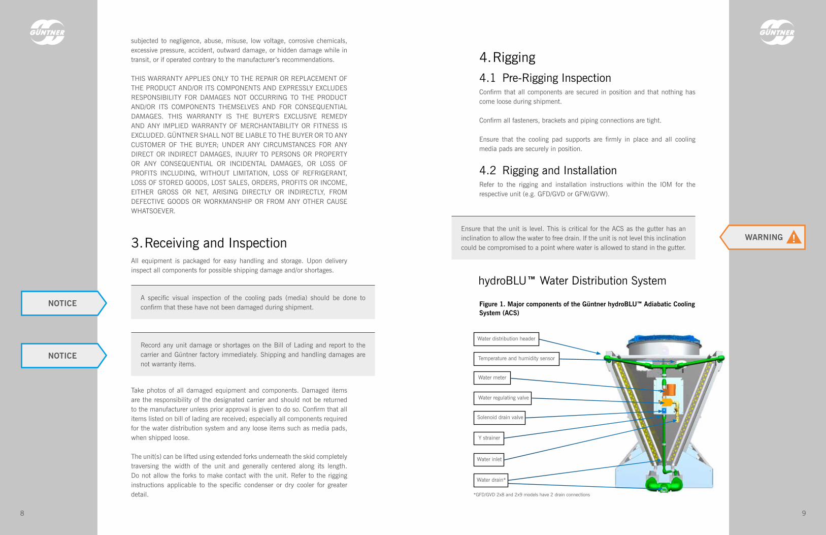
Figure 1. Major components of the Güntner hydroBLU™ Adiabatic Cooling System (ACS)
hydroBLU™ Water Distribution System
Water distribution header
Water meter
Water regulating valve
Solenoid drain valve
Y strainer
Water inlet
Water drain*
Temperature and humidity sensor
*GFD/GVD 2x8 and 2x9 models have 2 drain connections

1110
5. Start–Up5.1 System InspectionEnsure that all piping and components for the water distribution system are tight and secure.
Check to ensure that all media pads are securely held in position and that there are no visible gaps between the pads.
If required, clean the media pads using low pressure water in a range from 30 to 45 psig (2-3 bar).
It is recommended to clean and flush the distribution headers prior to allowing any water to flow over the pads, opening the drain header valve/
5.2 Preliminary Operation ModeThe inlet water pressure must be 20-60 psig (1.5-4 bar) for GFW/GVW and 25-60 psig (1.75-4 bar) for GFD/GVD. hydroBLU™ systems has been set according to factory setting table below:
The Güntner hydroBLU™ ACS accessory includes the following major components:
• Water Distribution System with water regulating valve, Y strainer, solenoid drain valve, water meter, and drain piping
• Ambient humidity and temperature sensor
• Evaporative cooling pads
• Water collection gutter
• Single drain connection* (*Except GFD/GVD 2x8 and 2x9 models)
• The Güntner Hydro Management Controller (GHM) which manages the water system.
• The Güntner Motor Management Controller (GMM) which is wired and mounted in factory
The majority of these components can be identified in Figure 1 shown above.
All connecting piping to the water distribution system must be supported independently. The unit and associated piping, is not designed to bear any additional piping loads.
All connecting piping to the water distribution system must be supported independently. The unit and associated piping is not designed to bear any additional piping loads. Failure to comply with this will result in damage to the system and void all warranties.
NOTICE
cap. After flush, close the valve/cap.
This can be accomplished by opening the valve/cap at the end of the distribution header on the opposite end to the water inlet side and allowing water to flow through the headers until no dust, dirt or debris is visible.
Confirm that all drain piping has been completed and water flows freely out of the gutters. Drain piping installation on site shall avoid overflow in gutters.
Figure 2. Service ball valve for cleaning and flushing distribution headers

1312
There are only two set points, which must to be modified in field by the customer before to startup the unit:
• Geodetic Height: This value needs to be entered to GHM in order to consider the air density depending the height where the unit will be placed. This is a metric value, and must be entered in meters above sea level.
• Outdoor temperature: The switch point setting needs to be entered in the GHM. This set point will initiate the water flow over the adiabatic pads. This value can be a preset ambient temperature, or a specific fluid temperature.
For more information on the set-up and functioning of the GHM, please refer to the GHM IOM. Alternatively, see the Quick GHM startup video on Güntner websites: http://www.guntnerus.com and http://www.guentner.com.mx
Prior to system start-up, verify the operation of the water distribution system with the following steps:
1. Enter an outdoor temperature set point that is lower than the actual ambient temperature on the GHM controller
2. Enter a water threshold (minimum water flow required to turn on the hydroBLU™ system) 10% lower than the unit requires
3. Modify set point on GMM to a value 20 °F lower than the actual process temperature
4. Once finished points 1 to 3 mentioned before, verify that the water regulating valve has being activated and allow water flow through media pads (The discoloration of the media, once wetted, will be clearly visible). This confirms a properly functioning of hydroBLU™ system
1. Parameters required for Start-up
Parameter Factory setting
Geodetic height (in meters) 540 (Monterrey)*
Airflow (xx*1000 m3h) According to model**
Air speed (m/s) According to model**
Max. Water Flow (l/h) According to model**
Drive parameter (EC, FU, PC) EC
Electric power (kW) fans According to model**
2. Parameters required after Start-up
Parameter Factory setting
Wetting Humidification on Humidification off Outdoor temperature
98%85%22°C*
Draining Non-operating Outdoor temperature T<
24 h6°C
Water parameter Water threshold (Base value) Full load mode Increment Delay Max H2O supply H2O Offset
According to model** 100%0%3 min1.31.0
Selection IP/SI Selection *SI
*Adjustable value on field by customer according with each site or Customer requirements. **Variable value according with each unit depending of unit model (G_W or G_D) and fan quantity. Find this value on datasheet or Table 2 and Table 3 of this IOM.
Table 1. Parameters required for start-up water control system
Figure 3. The regulating valve will automatically meter the exact water flow rate to be evaporated as required by the GHM controller.
Water Regulating Valve
1514
Figure 4. Water distributes from above the media pads, which transition from dry to saturated
5. Ensure that there is no water carry over outside of the pad area
5.3 Operation Mode1. Enter the desired ambient temperature set point in the GHM. This will
be the switch point at which time, water supply to the adiabatic pads may be initiated.
2. The minimum water threshold is preset in the GHM and is dependent on the unit size.
3. Enter the desired temperature set point in the GMM.
Only when all three of the above parameters are met, will the water supply to the adiabatic pads be initiated.
When the ambient temperatures drop below 43°F (6°C ) the system will drain automatically
If water carry over outside the unit occurs, please contact your Güntner representative to evaluate the case. Please note that 5% of water carry over is permissible.
NOTICE
NOTICE
6. Extended Shut DownIf the system will be shut down for a period of three weeks or more, please ensure the following:
Lock out, and tag, all electrical power supplies.
The hydroBLU™ water system uses a normally open solenoid valve to ensure water is drained from the system in the event of a power outage. Assure that drain solenoid valve is open.
The media pads must be removed from the unit and placed in a well- ventilated storage area and not exposed to sunlight.
6. Confirm that all water caught in the gutters is able to free drain unobstructed

1716
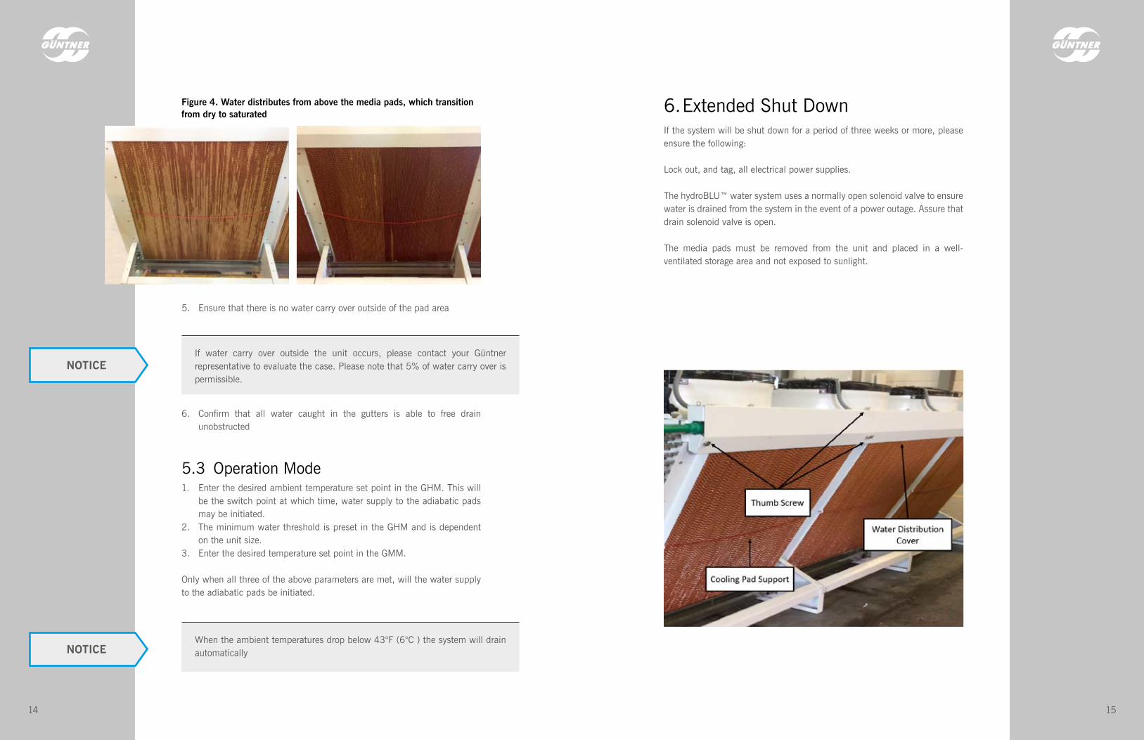
To remove the cooling pads:
• Remove the thumb screws and lift to open the header cover.
• With the header cover open, remove the top cooling pads by simply lifting them up and out.
• Loosen the thumb screws on the cooling pad support and slide the cooling pad support out and down to create space for the removal of the bottom cooling pads.
• Lift the bottom cooling pads up out of the gutter and then out to remove.Water distribution header cover
Water distribution header cover
Thumb screws
Ball valve for flushing water distribution header
Thumb Screw
Media Padsavailable to remove

1918
7. hydroBLU™ System OperationThe hydroBLU™ System is an adiabatic cooling process with an innovative and high technology control system which manages the water and energy consumption based in 4 main parameters
1. Fluid Temperature2. Ambient condition (Outdoor temperature and Humidity)3. Fan speed4. Water flow
The principle behind the adiabatic cooling process is that as water evaporates the surrounding air becomes cooler and more humid. This is a natural occurrence. Therefore, a portion of the water which is distributed over the media pads will evaporate. The heat that is needed for the evaporation process is removed from the air. The air that leaves the pad is therefore cooled and humidified simultaneously resulting in the temperature of the air entering the finned heat exchange surface being closer to the wet bulb temperature. This process permits a lower entering dry bulb temperature onto the finned heat exchange surface; effectively creating a greater approach and thereby utilizing less finned surface for the heat rejection requirement(s).
Each unit fitted with the adiabatic cooling media pads has a high cooling efficiency with maximum water flow for optimum operation. This water flow and fan speed will be controlled by GHM-GMM controls according 4 main parameters settings, provide accuracy fluid temperature with smart control for water and energy saving.
The hydroBLU™ system can operate at partial or full water flow, or dry, dependent on ambient conditions and the fluid temperature / pressure. Under normal operation, with either full or partial water flow, a portion of the water will be evaporated. Water which is not evaporated will flow across the pads, providing a “cleaning” function and into the gutter. The drain outlet (gutter outlet) should be routed to a waste water drain.
Fan Quantity G_W
Maximum water flow for hydroBLU™ Minimum water flow(Water Threshold)
l/hr US GPM l/hr US GPM
1 365 1.6 34 0.15
2 705 3.1 68 0.3
3 1070 4.7 102 0.45
4 1410 6.2 136 0.6
5 1775 7.8 170 0.75
6 2115 9.3 204 0.9
7 2480 10.9 238 1.05
8 2815 12.4 273 1.2
IMPORTANT NOTE: For GFW/GVW supplier water pressure must be 1.5 bar (20 psig) to 4 bar (60 psig)
Fan Quantity G_D
Maximum water flow for hydroBLU™ Minimum water flow(Water Threshold)
l/hr US GPM l/hr US GPM
2x2 975 4.3 91 0.4
2x3 1460 6.4 136 0.6
2x4 1950 8.6 182 0.8
2x5 2435 10.7 227 1
2x6 2920 12.9 273 1.2
2x7 3410 15.0 318 1.4
2x8 3900 17.2 363 1.6
2x9 4380 19.3 409 1.8
IMPORTANT NOTE: For GFD/GVD supplier water pressure must be 1.75 bar (25 psig) to 4 bar (60 psig)
Table 2. hydroBLU™ Water flow for GFW / GVW
Table 3. hydroBLU™ Water flow for GFD / GVD
Determine the number of fans from the model nomenclature, as underlined in the following examples:
GFW ###.#2-*(*) - #/## has 2 fans [such as GFW 090.1/2 - L(L) - F4/01GFD ###.#.*/2x2 - **#* has 2 x 2 fans, or 4 fans totalAGVD ###.#.*/2X6 - **#* has 2 x 6 fans or 12 fans total
Partial wetting of the adiabatic pads is a normal operation for the hydroBLU™ system. The pads will only be completed wetted when water flow is at 100%. NOTICE
WARNING!Inlet supply water pressure MUST be between 1.5 bar (20 psig) and 4 bar (60 psig) for GFW/GVW, and between 1.75 bar (25 psig) and 4 bar (60 psig) for GFD/GVD.

2120
8. Water Quality GuidelinesTypical municipal and well water supplies are suitable for use on the ACS. The application of other water sources, cleaning agents, or treatments must be compatible with the materials of construction. The ACS components include polypropylene piping, brass valves and fittings, PVC distribution headers, cellular media, and type 304L stainless steel frames and gutters.
9. Cooling Pad Media GuidelinesThe functionality of the hydroBLU™ system is such that the evaporation of the water occurs at the pad media surface as it flows over and through the pads. Standard water treatment practices are therefore somewhat different to standard heat exchanger practices. The hydroBLU™ methodology is to provide just the required water quantity to the pads to maintain the process temperature, or pressure, set point.
Many water related problems can be avoided if good system design and basic housekeeping practices are followed.
• The hydroBLU™ system is designed to operate with partial or completely wetted pad media. In some conditions excess water will flow into the gutter(s).
• Clean and flush distribution PVC headers on a regular basis to prevent buildup of deposits or microbiological growth.
• Replace damaged or spent pad media.
• At times or specific locations when the pad media experiences extreme evaporation, a flush cycle is recommended every 24 hours with the fan off.
• Locate the equipment and use appropriate water sources to minimize or avoid ingestion of contaminants that can clog or damage the media pads. Some examples include airborne dust/debris and exhaust air from other processes or equipment.
Designation Lower Upper Unit
Conductivity - < 450 microSiemens/cm
Calcium Hardness (as CaCO3) - < 170 ppm [mg/l]
Chlorides (as Cl) - < 50 ppm [mg/l]
Total Alkalinity (as CaCO3) - < 170 ppm [mg/l]
pH 6.5 8.5 -
Sulfate (SO42) - < 250 ppm [mg/l]
Silica (as SiO2) - < 25 ppm [mg/l]
Iron (as Fe) - < 0.2 ppm [mg/l]
Oil and grease - < 2 ppm [mg/l]
Total dissolved solid - < 550 ppm [mg/l]
Suspended solids - < 5 ppm [mg/l]
Colony-forming units - < 50 ppm [CFU/ml]
Table 4. hydroBLU™ Water Quality Parameters
WARNING!Failure to adhere to these water inlet quality parameters will reduce the lifespan of the adiabatic pads. Further, scaling, sometimes severe, can also occur.
10. Cooling Pad Media Maintenance• Avoid harmful contaminants including dust, dirt, fumes and harsh
cleaners.
• Use only low pressure water in a range from 30 to 45 psig (2-3 bar) to clean the pad media.
• Drain and disinfect the entire water distribution system quarterly with compatible concentrations of disinfectants with ball valve in PVC header open.

2322
12. Adiabatic Cooling System Controls12.1 Guntner Hydro Management (GHM)The wetting system is used to increase the capacity of heat exchangers at peak load times with high external temperatures and for more efficient heat dissipation with moderate ambient temperatures making efficient use of the water consumption. The adiabatic evaporation of the water on the media pads cools the air drawn in by the heat exchanger, which increases the heat exchanger’s capacity. The wetting controller GHM governs the regulation of the wetting process. The required water volume is calculated on the basis of the load state, the ambient temperature and the relative humidity. The GHM sets the appropriate water volume using the water regulating valve. The system’s frost protection is secured with automatic draining. The water supply to the unit must be protected separately against frost.
11. Maintenance
Recommended Inspection and Maintenance Frequencies
Start-Up Weekly Monthly Quarterly Annually Shut-down
Inspect and Clean as Required
Visually inspect pads for bowing, sagging or dry streaks
x x x x
Inspect gutters and remove any debris x x x x
Check water distribution system for leaks and clogged distribution holes
x x x
Flush water distribution system x x x
Drain and disinfect the entire water distribution system
x
Check water flow rate and adjust if necessary x x x
Check water distribution is even across entire length of unit
x x x
Remove all dirt and debris from the media pads x x
Clean the Y Strainer’s mesh x x
There are three possible operating conditions when the Güntner ACS accessory is included on a GF/VW unit when utilizing the Güntner Motor Management Controller
• Dry Mode• GHM Water Saving Mode• GHM Energy Efficiency Mode• GHM Manual Mode
12.2 Dry ModeThis is the standard operating mode for the unit when ambient temperature and process are within the design operating conditions. In this operating mode the GMM (Güntner Motor Management) controls motors and regulate the speed to achieve the desired process set-point, no water is used in this operating condition.
12.3 GHM Water Saving ModeOnly as much water as the media pads can evaporate is applied. hydroBLU™ technologies works with this mode as standard.
12.4 GHM Energy Efficiency ModeMore water is used in this mode, as the focus is on conserving as much fan power as possible.
12.5 GHM Manual Mode• Manual mode is used to operate the system’s water inlet valve and
drainage valve by hand.• Manual mode does not depends on DI1 enabling.• Manual mode has the highest priority and switches all other control
types off.• The prerequisite for switching on the manual mode is the set external
temperature.• This must be above the frost temperature, as otherwise the manual
mode cannot be switched on. Wetting is not permitted in the manual mode without recording the external temperature.
• The fact that manual mode is active is recorded permanently. In other words, it will still be active after you have switched the system off and back on.

2524
12.5.1 Manual Mode ON / OFF12.6 Adjusting Settings on the GHM
Cancel and return to INFO menu
Enter key for function selection; change to EDIT mode and value acceptance
Right arrow for moving to the next menu level
Left arrow for moving to the previous menu level
Up / down arrows for scrolling through the menu level
1. Use this key to move from the “INFO” menu to the Operating menu2. Use this key to retun to the “INFO” menu at any time
Manual mode - valve control value/draining

2726
12.7 Edit Mode
Select menu option you want(top line)
This mode is required to change values (control values, for example).
For more information on the set-up and functioning of the GHM, please refer to the IOM for the GHM or in GHM startup video on Güntner web site.
New value acceptance
Change value
Change to menu option
Decimal point selection(cursor flashes)
Change to writing mode(cursor flashes)
NOTES

Guntner U.S. LLC3601 Algonquin Road, Suite #925Rolling Meadows, IL 60008USA
Phone: + 1 847 781 0900www.guntnerus.com
Members of Güntner Group
Air Cooled CondensersAir Cooled Fluid CoolersAir CoolersEvaporatorsEvaporative CondensersEvaporative Fluid CoolersClosed Circuit Fluid Coolers
Subj
ect t
o te
chni
cal a
men
dmen
ts w
ithou
t prio
r not
ice.
IO
M 1
14 /
V1.1
/ EN
G / 0
4.20
19