adhesion testing by the scratch test method: the influence...
TRANSCRIPT

Thin Solid Films. 154 (1987) 333-349
333
ADHESION TESTING BY THE SCRATCH TEST METHOD: THE INFLUENCE OF INTRINSIC AND EXTRINSIC PARAMETERS ON THE CRITICAL LOAD*
P. A. STEINMANN?, Y. TARDY AND H. E. HINTERMANN
Swiss Centrefor Electronics and Microtechnology Inc.. CH-2007 Neuchritel (Switzerland)
(Received March 16,1987)
The critical load determined by the scratch test is widely regarded as representative of coating adhesion.
Depending on the coating-substrate system to be measured, the critical load can be detected by acoustic emission, and/or by optical or scanning electron microscopy and/or by the variation of the tangential frictional force applied to the sample. It remains, however, difficult to express quantitatively the adherence because the critical load depends on several parameters related to the testing conditions and to the coating-substrate system.
Both intrinsic parameters, such as scratching speed, loading rate, diamond tip radius and diamond wear, and extrinsic parameters, such as substrate hardness, coating thickness, substrate and coating roughness, friction coefficient and friction force, are considered in order to improve the interpretation of the critical load results.
As well as the experimental relations between critical load and these different parameters, the results of a theoretical approach are also presented. The deform- ations and stress distributions near the interface caused by the static indentation of a spherical point have been simulated by the finite element analysis. Despite the fact that these calculations have been made in the static mode, they permitted a better understanding of the failures observed in and near the scratches; this represents a justification for the use of a scratch test to characterize the mechanical resistance (adhesion and cohesion) of a coating deposited on a tough substrate.
1. INTRODUCTION
In the field of protective and wear-resistant coatings, the scratch test is being used more and more to evaluate and to control the mechanical resistance of the
* Paper presented at the 14th International Conference on Metallurgical Coatings, San Diego, CA,
U.S.A., March 23-27, 1987.
t Present address: Lewis Research Center, National Aeronautics and Space Administration, Cleveland,
OH 44135, U.S.A.
OO40-6090/87/%3.50 0 Elsevier Sequoia/Printed in The Netherlands

334 P. A. STEINMANN, Y. TARDY, H. E. HINTERMANN
coating-substrate interface. The development during the last 30 years and the operating principle of this test have been described on several occasions in the
literaturelp5. Essentially the test consists in deforming the coating-substrate interface by straining the substrate. The mechanical resistance of the interface and/or of the coating is characterized by a critical load which is the minimum load at
which damage by lack of adhesion can be observed. The critical load depends of course on the coating adhesion but also on several
other parameters; some of these are directly related to the test itself (the intrinsic parameters) others are related to the coating/substrate combination (the extrinsic parameters). The aim of this paper is to discuss the influences of the intrinsic and extrinsic parameters on the critical load, in connection with the scratch test, to allow an improved interpretation of the critical loads and the coating adhesion evaluation.
The samples used for this study consisted of TIC-, Ti(C,N)- or TiN-coated steels or cemented carbides, deposited by chemical vapour deposition (CVD) and physical vapour deposition (PVD) techniques. First, the influences of the following intrinsic parameters, loading rate, scratching speed, tip radius and wear rate, and the following extrinsic parameters, substrate hardness, coating thickness, substrate and coating roughnesses, friction coefficient between tip and coating and the friction force in the scratching direction have been examined. Using the reported experi- mental results, it was possible to put forward some empirically desired relationships.
In the second part of this paper, there is ihe presentation of a theoretical approach based on the model of a static spherical indenter pressed on the coating surface. The stress distribution caused by the indenter in the interface region has been calculated and studied as a function of the substrate nature by numerical simulation using the finite element method. The simulated and experimental indentation data obtained on Tic-coated steel substrates are compared.
2. INSTRUMENTATION
The experimental results presented in this paper have been obtained by means of the Revetest Automatic Scratch Tester 4,6,7 (Centre Suisse d’Electronique et de Microtechnique) using a Rockwell C diamond (conical angle, 120”; hemispherical tip of 200 urn radius); it performs scratches under either constant or linearly increasing load.
This instrument is equipped with an integrated optical microscope, an acoustic emission detection system and a device to measure the tangential frictional force (in the scratching direction), giving the friction coefficient value during scratching. The operator can determine the critical load for a coating-substrate system by optical, acoustical or mechanical methods. When series of similar samples have to be tested for their critical load, the main criteria to be used are first acoustic emission and second the frictional force; these two criteria, however, do not replace the optical observation which in addition gives useful indications on the size and nature of the failures. In most cases it can be said that the three methods provide complementary information.

ADHESION TESTING BY THE SCRATCH TEST METHOD 335
3. INFLUENCE OF THE PARAMETERS ON THE CRITICAL LOAD
3.1. Intrinsic parameters The intrinsic parameters associated with the scratch test are directly related to
the instrumentation and can therefore be chosen by the operator. 3.1.1. Loading rate andscratching speed Scratches under different loading rates dL/dt and scratching speeds dxldt have
systematically been performed on a CVD Tic-coated tool steel (D2; 1.2601). The deposition conditions for these coatings were as follows: temperature, 1000°C; duration, 2.5 h; gas mixture, 4% H,, 4% CH,, balance TiCl,; pressure, 50 Torr. The coating thickness is 3.5 urn and the substrate hardness after quenching and tempering is 7000 MPa. Table I contains the critical load results obtained by averaging the data for three different scratches. The first observation is that the critical load is independent of the loading rate and the scratching speed, provided that their variations are proportional, e.g. the ratio dL/dx remains constant (Fig. 1).
TABLE I
CRITICAL LOAD VALUES, USING A DIAMOND TIP RADIUS R = 200Fm, MEASURED WITH DIFFERENT
SCRATCHING SPEEDS AND LOADING RAN 0N cvD TiC(3.5 Km) COATED s-nx
dx/dt dL1c.h dLJClX (mm min- ‘) (N mine’) (N mm-‘)
Critical load” Lc (N)
2
2
2
2
3
3
2
3
5
10
15
2
5
10
20
30
10
10
10
20
30
3
10
30
200
140
120
100
120
90
40
60
100
200
300
20
50
100
200
300
50
30
20
20
30
0
0
0
100 34
70 32
60 30
50 28
40 29
30 28
20
20
20
20
20
10
10
10
10
10
5
3
2
1
1
0
0
0
26
26
25
24
24
23
25
24
22
22
23
22
19
18
17
18
17
16
‘R=2OOpm.

336 P. A. STEINMANN, Y. TARDY, H. E. HINTERMANN
LOADING RATE dL/dt[N/mml 100 x0 1w I ’ ’ 7 .I
SCRATCHING SPEED dxldt [mmhnl
Fig. 1. Variation in the critical load Lc measured with a diamond tip radius R of 100 urn (0) 200 urn (o),
300 urn (0) and 600 urn (m), as a function of different loading rates and scratching speeds.
These results are valid for a tip radius of 200 pm, but also for tip radii of 100,300 and 600 nm; this aspect will be discussed later.
Consequently, the dL/dx ratio is a significant parameter for the scratch test; the dependence of the critical load on this parameter is shown in Fig. 2. The critical load decreases when the dL/dx ratio decreases; the differential critical load variations become more important for the lower dL/dx values. This behaviour is explained by the fact that, when dL/dx decreases, the probability of encountering defective adhesion of the coating within a certain load range increases: this consequently results in a decreased critical load. Therefore, when the loading rate is kept constant, the critical load decreases when the scratching speed increases (Fig. 3(a)); when the scratching speed remains constant, the critical load increases when the loading rate increases (Fig. 3(b)).
DOW RATID dL/dx I N/mm1
Fig. 2. Variation in the critical load Lc measured with a diamond tip radius R = 200 pm as a function of the loading rate over scratching speed ratio dL/dx.

ADHESION TESTING BY THE SCRATCH TEST METHOD 337
Fig. 3. Variation in the critical load Lc measured with a diamond tip radius R = 200 pm on CVD TiC on
steel. (a) Lc as a function of the scratching speed dx/dt for different dL/dx values: 0,200 N min-‘; n , lOONmin_‘; q ,20Nmin-‘; 0, 0 N min-‘. (b) L, as a function of the loading rate dL/dt for different
dL/dxvalues:0,2mmmin-‘;~,10mmmin-L.
The lowest critical loads are obtained for dL/dx = 0, i.e. for measurements performed under constant load. This experimental result is in disagreement with the observations made by Perry and PulkerS with optical coatings deposited on glass substrates.
3.1.2. Indenter tip radius To determine the influence of the tip radius on the critical load, the same TiC-
coated steel samples as described above were used. The critical loads obtained by diamonds with different tip radii of 100,200,300 and 600 pm are shown in Table II. The average pressure P,,, applied by the spherical point and related to the plastic deformation of the substrate at the moment the critical load is reached is an approximation of the substrate hardness’
where b is the half-width of the scratch. Because b is proportional to the indenter tip radius R, expression (1) shows that the critical load must be proportional to R*. The experimental results presented in Fig. 4 show, ‘however, that the critical load variation is not proportional to R*, but varies from R”.” to R”“, depending on the value of the dL/dx ratio.
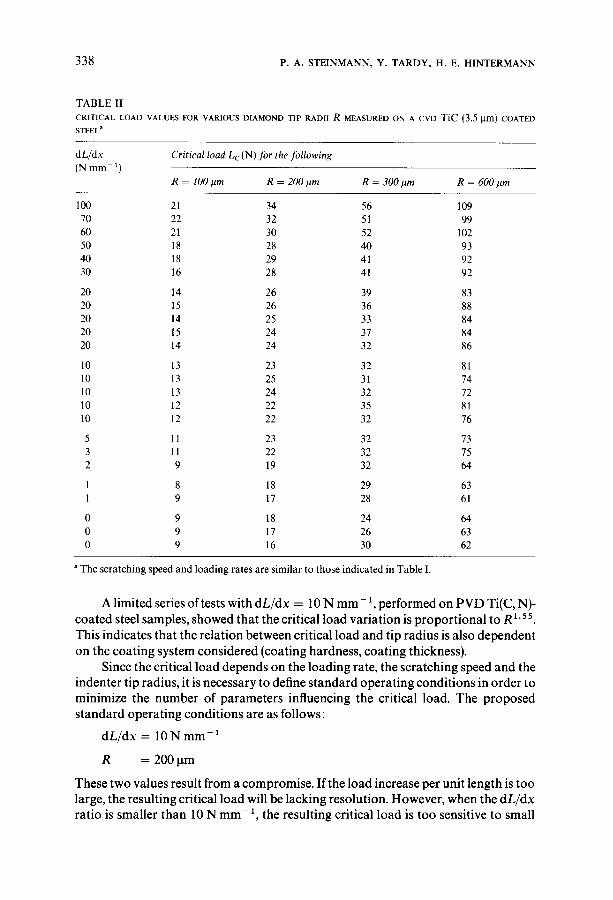
338 P. A. STEINMANN, Y. TARDY, H. E. HINTERMANN
TABLE II
CRITICAL LOAD v~Lui5.5 FOR VARIOUS DIAMOND TIP RADII R MEASURED 0~ A CVD TiC(3.5l.tm) COATED
STEELa
dL/dx Critical load L,(N) for the following (N mm- ‘)
R = 100pm R = 200 pm R=SOOpm
100 21 34 56
70 22 32 51
60 21 30 52
50 18 28 40
40 18 29 41
30 16 28 41
20 14 26 39
20 15 26 36
20 14 25 33
20 15 24 31
20 14 24 32
10 13 23 32
10 13 25 31
10 13 24 32
10 12 22 35
10 12 22 32
5 11 23 32
3 11 22 32
2 9 19 32
1 8 18 29
1 9 17 28
0 9 18 24
0 9 17 26
0 9 16 30
a The scratching speed and loading rates are similar to those indicated in Table I.
R = 600pm
109
99
102
93
92
92
83
88
84
84
86
81
14
12
81
76
73
75
64
63
61
64
63
62
A limited series of tests with dL/dx = 10 N mm-‘, performed on PVD Ti(C,N)- coated steel samples, showed that the critical load variation is proportional to R’.55.
This indicates that the relation between critical load and tip radius is also dependent on the coating system considered (coating hardness, coating thickness).
Since the critical load depends on the loading rate, the scratching speed and the indenter tip radius, it is necessary to define standard operating conditions in order to minimize the number of parameters influencing the critical load. The proposed standard operating conditions are as follows:
dL/dx = 10 N mm-’
R = 2OOum
These two values result from a compromise. If the load increase per unit length is too large, the resulting critical load will be lacking resolution. However, when the dL/dx ratio is smaller than 10 N mm- I, the resulting critical load is too sensitive to small
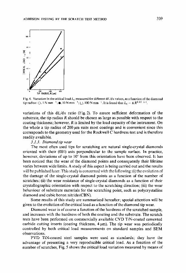
ADHESION TESTING BY THE SCRATCH TEST METHOD 339
Fig. 4. Variation in the critical load Lc measured for different dL/dx values, as a function of the diamond
tip radius: 0, 1 N mm-‘; l ,lON mm-‘; 0, 1OON mm-‘. It is found that L, = KR0.85-‘.‘.
variations of this dL/dx ratio (Fig. 2). To assure sufficient deformation of the substrate, the tip radius R should be chosen as large as possible with respect to the coating thickness; however, R is limited by the load capacity of the instrument. On the whole a tip radius of 200 urn suits most coatings and is convenient since this corresponds to the geometry used for the Rockwell C hardness test and is therefore readily available.
3.1.3. Diamond tip wear
The most often used tips for scratching are natural single-crystal diamonds oriented with their (001) axis perpendicular to the sample surface. In practice, however, deviations of up to lo” from this orientation have been observed. It has been noticed that the wear of the diamond points and consequently their lifetime varies between wide limits. A study of this aspect is being carried out and the results will be published later. This study is concerned with the following: (i) the evolution of the damage of the single-crystal diamond points as a function of the number of scratches; (ii) the wear resistance of single-crystal diamonds as a function of their crystallographic orientation with respect to the scratching direction; (iii) the wear behaviour of substitute materials for the scratching point, such as polycrystalline diamond and cubic boron nitride (CBN).
Some results of this study are summarized hereafter; special attention will be given to the evolution of the critical load as a function of the diamond tip wear.
Diamond wear is of course a function of the hardness of the scratched sample, and increases with the hardness of both the coating and the substrate. The scratch tests have been performed on commercially available CVD TiN-coated cemented carbide cutting inserts (coating thickness, 4 urn). The tip wear was periodically controlled by both critical load measurements on standard samples and SEM observations.
PVD TiN-coated steel samples were used as standards; they have the advantage of presenting a very reproducible critical load. As a function of the number of scratches, Fig. 5 shows the critical load variation measured by means of

340 P. A. STEINMANN, Y. TARDY, H. E. HINTERMANN
Fig. 5. Variation in the critical load L, measured on a standard sample using different diamonds as a
function of the number of scratches. (a) Diamonds oriented along their (110) axis with respect to the
scratching direction: 0, diamond 4; +, diamond 39; 0, diamond 47. (b) Diamonds oriented along their
(100) axis with respect to the scratching direction: 0, diamond 33; +, diamond 53; c], diamond 84.
three diamonds oriented along (110) (Fig. 5(a)) and three diamonds oriented along (100) (Fig. 5(b)); these diamonds were oriented with respect to the scratching direction. These tests show that the critical loads varied from one diamond to another but that, for one individual diamond, the critical load did not vary much with the number of scratches performed. As can be seen in Fig. 6, the first signs of tip wear appear as a polishing of the point; Fig. 6(a) presents the initial state whereas Fig. 6(b) shows the polishing of the point. The next and almost simultaneously observed damage is the formation of a half-crown-shaped track on the face of the point which is in contact with the scratched coating (Fig. 6(b)). This typical wear appearance increases progressively without changes in the critical load value (Figs. 6(c) and 6(d)). Similar tests have been performed using diamonds with random orientation with respect to the scratching direction. One such diamond is shown in Fig. 7(a), after 70 scratches; although the wear is significant the critical load has not changed. Only when the tip damage has increased noticeably as shown in Fig. 7(b), after 145 scratches, are the critical load values influenced and they no longer reflect the adherence of the tested system. The wear mechanism mentioned above is typical for all single-crystal diamonds used for this study; however, the stages at which these damages occur are not reproducible and change from one diamond to another. The main reasons for these variations are the following: the chemical composition of the diamond with respect to the inclusions and surface impurities, the surface quality and the initially present microcracks. In an excellent survey, Wilks’ has reported that damage by fatigue through microcracks is the main reason for deterioration of

ADHESION TESTING BY THE SCRATCH TEST METHOD 341
(4
04
Fig, 6. Wear behaviour of the point ofdiamond 84, scratching in the(100) direction: (a) before scratching;
(b) after 33 scratches showing start of the “half-crown” wear appearance; (c) after 65 scratches; (d) after
125 scratches. (Magnification, 300 x .)
heavily stressed single-crystal diamonds. Scanning electron microscopy viewing of the diamond tips shows that those oriented along the (100) direction with respect to the scratching direction have a better wear resistance than those oriented along the (110) direction. The half-crown-shaped crack pattern appears also after a larger number of scratches. It is advised therefore that the diamonds are oriented along the (100) direction. The lifetime of a diamond can be extended through regular microscopic observations, since the diamond can be rotated through 180” before catastrophic damage is reached.
The use of polycrystalline diamond points as a substitute was not satisfactory; the two tested points showed rapid and irregular wear even after only 15 scratches owing to the different crystallographic orientations of the individual grains, to the grain boundaries and to the residual porosity.
The CBN point has shown promising results, but unfortunately only one point has been tested so far. The damages caused by this CBN indenter are perfectly

342 P. A. STEINMANN, Y. TARDY, H. E. HINTERMANN
(b)
Fig. 7. Wear behaviour of the point of diamond 92: (a) after 70 scratches; (b) after 145 scratches. (Magnification, 300 x ,)
comparable with those produced by single-crystal diamond. The critical load evolution as a function of the number of scratches is very regular. The evolution of the CBN point wear as a function of the number of scratches differs from that of the diamond points; the typical “half-crown” deterioration of the diamond points has not been observed on the CBN point; instead, a progressive flattening of the tip has been observed. However, the critical loads determined on the standard samples and on the CVD TiN-coated cutting inserts are lower than those obtained by means of the single-crystal diamond points. This is due to the different friction coefficient values corresponding respectively to the CBN-TiN and diamond-TiN friction partners. This aspect will be discussed in more detail later.
3.2. Extrinsic parameters The extrinsic parameters influencing the scratch test depend directly on the
coating-substrate system. It is of particular importance that this influence is known since these parameters are fixed and cannot be modified by the operator.
3.2.1. Substrate hardness and coating thickness
The influences of the substrate hardness and the coating thickness on the critical load have been reported in the literature on several occasions3P8,10P18.
The extent of the coating-substrate assembly deformation caused by the scratching point is mainly dictated by the substrate deformation. When the substrate hardness is increased, there is need for a higher load to obtain the same plastic deformation. If it is assumed that the adhesion is the same and that the critical load is determined by the degree of deformation, then the critical load should increase with the substrate hardness. This is exactly what is observed.
By the same reasoning, it can be stated that a coating thickness increase requires an increased load to obtain the same degree of deformation and therefore

ADHESION TESTING BY THE SCRATCH TEST METHOD 343
the critical load increases with the coating thickness. Publications by several researchers on these aspects agree with the fact that the critical load increases with both substrate hardness and coating thickness increases4p6*‘0-‘2* 15.
3.2.2. Coating roughness Scratch tests on CVD Tic-coated cemented carbide cutting inserts from
different producers have shown that the critical load depends on the surface roughness. It has been observed by optical and electron microscopy and by acoustic emission that the critical load determined on coated cutting inserts having a roughness R, 2 0.3 pm is no longer significant. Because of different surface defects (peaks, holes and whiskers), the damage sites are mostly located within the coating itself. Under these conditions the critical load data cannot be considered as representative of the adhesion; an eventual higher critical load resulting from adhesive failures is difficult to observe, since the coating roughness complicates the microscopic observation.
3.2.3. Substrate roughness prior to coating The influence of the substrate roughness prior to the coating deposition on the
critical load has been determined on a series of six PVD (ion plating) TiN-coated high speed steel samples; the coating thickness was of the order of 2 pm. The samples underwent different surface preparations and the average and total roughnesses were measured by means of a profilometer. Table III presents the following data: the different surface preparations, the corresponding roughnesses and the critical loads. The roughness data obtained on the coated samples are similar to those obtained on the uncoated samples.
TABLE III
CRITICAL LOAD VALUES, USING A DIAMOND TIP RADIUS R = 200 )IIII, MEASURED ON A PVD TIN (2 pm)
COATED HIGH SPEED STEEL SUBSTRATE HAVING DIFFERENT SURFACE ROUGHNESS PRIOR TO THE COATING
TREATMENT
Sample Surface preparation
1 Polishing (600 grit paper) 0.03 0.40 56
2 Rectification 0.05 1.00 56
3 Polishing (alumina) 0.07 0.60 54
4 Shot peening 0.40 4.65 40
5 Milling 1.75 12.5 27
6 Shot blasting 7.00 70.0 I3
Average roughness
R, (pm)
Total roughness
R, km)
Critical
load
(NJ
The graph presented in Fig. 8 shows clearly the dependence of the critical load on the substrate roughness. It is, however, difficult to determine exactly the influence of the substrate roughness on the critical load since it is believed that the important differences in sample roughnesses also affect the adhesive properties of the coatings. Although all the substrates were coated during the same treatment, the adhesive properties can indeed vary since the efficiency of the cleaning operation is influenced by the surface roughness.

344 P. A. STEINMANN, Y. TARDY, H. E. HINTERMANN
Fig. 8. Variation in the critical load L, using a diamond tip radius R = substrate roughness: 0, R,; 0, R,.
200 pm as a function of the
3.2.4. Friction force andfriction coejicient
In addition to their dependence on the substrate hardness, the coating thickness and the surface roughness, the critical load and the tangential frictional force also depend on the friction coefficient between the indenter and the coating surface. The equipment which was used to perform the work reported here permitted the frictional force to be measured and the coefficient of friction to be calculated on-line. Scratch tests using both a conventional diamond point and a CBN indenter have been performed on four different coating-substrate systems. Optical microscopy, acoustic emission and frictional force have been used to determine the critical loads.
The critical load determined by the frictional force is that load at which a sudden change in frictional force occurs. Table IV shows the critical load and the coefficient of friction results measured between 0 and 10 N. The following conclusions may be drawn.
(1) The three criteria used to define the critical load give comparable results. It is, however, obvious that it is not possible to define the critical load using only the frictional force data. The frictional force and more precisely the coefficient of friction
are very useful data as a complement to the acoustic emission signal and the optical microscopy observation.
(2) If a specific coating-substrate system is considered, it can be said that the critical load depends on the frictional coefficient; higher values for the coefficient of friction correspond to lower critical load values.
(3) On carbide coatings the same friction coefficients were obtained with both diamond and CBN tips. Therefore the critical loads obtained with these two indenter types are similar.
(4) On nitride coatings the friction coefficients determined with both a diamond point and a CBN point are different; therefore the critical loads obtained with these two indenter types are different. The coefficient of friction data determined in the scope of this work are in agreement with friction data obtained on a conventional pin-disc type of tribometer and published by Hintermann”, who observed indeed that the friction coefficients between carbides and nitrides (diamond-TiN) are lower than those obtained between nitrides and nitrides (CBN-TiN).
The data mentioned here above show that the coefficient of friction is a parameter with an important influence on the critical load.

TA
BL
E
IV
CR
ITIC
AL
LO
AD
V
ALU
ES
M
EA
SU
RE
D,
US
ING
B
OT
H
DIA
MO
ND
A
ND
C
UB
IC
BO
RO
N
NIT
RID
E
PO
INT
S
WIT
H
A
TIP
R
AD
IUS
R
= 2
00 p
m,
BY
O
PTIC
AL
MIC
RO
SC
OPY
, A
CO
US
TIC
EM
ISS
ION
A
ND
TH
E
FR
ICTIO
NA
L
FO
RC
E
VA
RIA
TIO
N
AN
D
TH
E
FR
ICTIO
N
CO
EF
FIC
IEN
T
OF S
EV
ER
AL
CO
ATIN
G-S
UB
STR
ATE
S
YS
TE
MS
Dia
mon
d C
BN
Cri
tica
l lo
ad(N
)
OM
A
E
FF
Fric
tion
co
ejfi
cien
t C
riti
cal
load
(N)
OM
A
E
FF
Fric
tion
co
effi
cien
t
TiN
/ste
el
by P
VD
26
26
26
0.
04
22
21
21
0.08
TiN
/cem
ente
d ca
rbid
e by
CV
D
71
64
66
0.03
47
46
46
0.
10
Ti(
C,N
)/st
eel
by P
VD
11
10
14
0.
07
13
12
12
0.08
Tic
/cem
ente
d ca
rbid
e by
CV
D
27
22
23
0.12
26
23
25
0.
13
OM
, op
tical
m
icro
scop
y;
AE
, ac
oust
ic
emis
sion
; FF
, fr
ictio
n fo
rce.
346 P. A. STEINMANN, Y. TARDY, H. E. HINTERMANN
4. THEORETICAL APPROACH
The stress distribution near the coating-substrate interface, when it is indented statically by a spherical point, has been determined by mathematical simulation (finite element analysis).
Some results and conclusions of previous work20.21 on numerical simulations of the behaviour of Tic-coated steel substrate of different hardnesses, under loading by a static spherical diamond, are mentioned hereafter. The stress distributions near the interface region depend on the nature (especially hardness) of the substrate.
When the substrate is hard, one observes the following:
(1) Underneath the indenter: compressive stresses in the coating and in the substrate. (2) Around the indentation: strong tensile stresses at the coating surface, decreasing progressively from the surface to the interface, and compressive stresses in the substrate.
When the substrate is soft, one observes the following:
(1) Underneath the indenter: tensile stresses at the interface on the coating side, and compressive stresses in the substrate. (2) Around the indentation: a behaviour similar to that corresponding to the
hard substrate.
Therefore the maximum stress sites for the Tic-soft steel combination are expected at the interface underneath the indenter and at the coating surface around the indentation; for the hard substrate the maximum stresses are expected at the coating surface near the indentation. Although these observations were made by mathematical modelling of a static spherical point, neglecting herewith the indenter movement, they are confirmed by experimental observations during the scratch test. Indeed, when a coated soft steel undergoes scratching, adhesive failures are observed within the scratch itself (Figs. 9(a) and 9(b)); when a coated hard steel is scratched, cohesive or adhesive-cohesive failures are observed at the edges of the scratch (Figs.
9(c) and 9(d)). Identical observations have been made by Helmersson et al.” for TiN-coated
high speed steels of different hardnesses. They reported cohesive failures for high substrate hardnesses and adhesive failures for low substrate hardnesses. Experi-
mental investigations by Je et al. I8 also demonstrate that adhesive failures occur in the scratch marks of TiN-coated soft steel substrates.
Finally, by comparing micrographs of sections through indentations and the stress calculations in the interface regions, it can be concluded that the load corresponding to the critical stress at the interface depends on the substrate hardness. This confirms the experimentally determined relation between the scratch test critical load and the substrate hardness.
5. CONCLUSIONS
The analysis of the critical load dependences on the intrinsic and extrinsic

ADHESION TESTING BY THE SCRATCH TEST METHOD 347

348 P. A. STEINMANN, Y. TARDY, H. E. HINTERMANN
parameters of the scratch test leads to the following conclusions and recommendations.
(1) dL/dx = 10 N mm- ’ and R = 200 urn are proposed standard operating conditions; such standards are necessary in order to minimize the number of parameters influencing the critical load. When such standards are generally accepted they have the important advantage that results of different investigators in different locations using different equipment can be compared.
(2) The diamond tip wear affects the critical load, which depends on the number of scratches performed. However, experimental results show that the number of scratches which can be drawn without affecting the critical load will depend on the surface properties of each individual diamond selected. The use of preoriented (100) diamonds and regular optical observation of the tips can substantially increase their lifetime.
resul(ti! ’ re iminary tests performed with CBN yielded promising wear resistance
” (4) The scratch test corresponds basically to the deformation of the coating-
substrate assembly, which means essentially the deformation of the substrate; therefore it is logical that the critical load increases with substrate hardness and coating thickness, as observed.
(5) In order to obtain a representative critical load value, the sample surface roughness R, should not be higher than 0.3 urn (arithmetic average roughness).
(6) Since the adhesion is influenced by the surface preparation before coating, the initial roughness should be kept as low as possible.
(7) The measurement of the tangential frictional force is mainly useful for calculating the friction coefficient between tip and coating. In most cases the critical load cannot, however, be determined reliably by the frictional force; it should be confirmed by acoustic emission and microscopic observation data.
(8) The critical load depends on the friction coefficient measured between the tip and the coating; to an increased friction coefficient corresponds a decreased critical load value.
(9) The deformation and stress distribution caused by a static spherical indenter on the surface of a substrate-coating assembly have been simulated by means of the finite element analysis. Despite the fact that these simulations are for a static and not for a scratching indenter, they contributed largely to the understand- ing of the origin and nature of the failures observed on scratched coatings. Therefore it can be said that the use of a scratch test to characterize the mechanical resistance (adhesion and cohesion) of a hard coating deposited on a tough substrate is fully justified.
ACKNOWLEDGMENTS
The authors wish to thank Dr. H. Boving (Centre Suisse d’Electronique et de Microtechnique) for his encouragement and contribution to this paper and Dr. T. Spalvins (National Aeronautics and Space Administration) for critical reading of the manuscript. Part of this work was financially supported by the Swiss National Science Foundation.
ADHESION TESTING BY THE SCRATCH TEST METHOD 349
REFERENCES
1 J. Ahn, K. L. Mittal and R. H. MacQueen, in K. L. Mittal (ed.), Adhesion Measurement of Thin Films, Thick Films, and Bulk Coatings, ASTM Spec. Tech. Publ. 640, 1978, p. 134 (ASTM,
Philadelphia, PA).
2 A. J. Perry, P. Laeng and H. E. Hintermann, Proc. 8th Int. Conf. on Chemical Vapor Deposition, Electrochemical Society, Pennington, NJ, 1981, p. 475.
3 A. J. Perry, Thin SolidFilms, 107(1983) 167. 4 P. A. Steinmann, P. Laeng and H. E. Hintermann, Mafer. Tech., 13 (1985) 85. 5 J. Valli, J. Vat. Sci. Technol. A, 4 (1986) 3007. 6 P. A. Steinmann and H. E. Hintermann, J. Vat. Sci. Technol. A, 3 (1985) 2394. 7 A. J. Perry, Surf Eng., 2 (1986) 183.
8 A. J. Perry and H. K. Pulker, Thin SolidFilms, 124 (1985) 323. 9 J. Wilks, Precis. Eng., 2 (1980) 57.
10 P. Laeng and P. A. Steinmann, Proc. 8th In!. Co@ on Chemical Vapor Deposition, Electrochemical
Society, Pennington, NJ, 198 1, p. 723. I 1 B. Hammer, A. J. Perry, P. Laeng and P. A. Steinmann, Thin Solid Films, 96 (1982) 45. 12 E. Hummer and A. J. Perry, Thin SolidFilms, lOl(l983) 243. 13 W. D. Sproul, Thin SolidFilms, 107(1983) 141. 14 A. Pan and J. E. Greene, Thin Solid Films, 97 (1982) 79. 15 U. Helmersson, B. 0. Johansson, J. E. Sundgren, H. T. G. Hentzell and P. Billgren, J. Vat. Sci.
Technol. A, 3 (1985) 308. 16 K. L. Chopra, Thin Film Phenomena, McGraw-Hill, New York, 1969, p. 313. 17 B. W. Butter, C. T. H. Stoddart and P. R. Stuart, J. Phys. D, 3 (1970) 877.
18 J. H. Je, E. Gyarmati and A. Naoumidis, Thin Solid Films, 136 (1986) 57. 19 H. E. Hintermann, J. Vat. Sci. Technol. B, 2(1984) 816. 20 A. Vaucher and P. A. Steinmann, CSEM Tech. Rep. 36,51.0.52.2 1985 (Centre Suisse d’Electronique
et de Microtechnique, Neuchltel).
21 P. A. Steinmann and Y. Tardy, CSEM Tech. Rep. 71,51.052.3, 1986 (Centre Suisse d’Electronique
et de Microtechnique, Neuchltel).

本文献由“学霸图书馆-文献云下载”收集自网络,仅供学习交流使用。
学霸图书馆(www.xuebalib.com)是一个“整合众多图书馆数据库资源,
提供一站式文献检索和下载服务”的24 小时在线不限IP
图书馆。
图书馆致力于便利、促进学习与科研,提供最强文献下载服务。
图书馆导航:
图书馆首页 文献云下载 图书馆入口 外文数据库大全 疑难文献辅助工具