addressing protection challenges associated with type 3
TRANSCRIPT

Addressing Protection Challenges Associated With Type 3 and Type 4
Wind Turbine Generators
Bing Chen CG Power Solutions USA Inc.
Arun Shrestha, Fred A. Ituzaro, and Normann Fischer Schweitzer Engineering Laboratories, Inc.
© 2015 IEEE. Personal use of this material is permitted. Permission from IEEE must be obtained for all other uses, in any current or future media, including reprinting/republishing this material for advertising or promotional purposes, creating new collective works, for resale or redistribution to servers or lists, or reuse of any copyrighted component of this work in other works.
This paper was presented at the 68th Annual Conference for Protective Relay Engineers and can be accessed at: http://dx.doi.org/10.1109/CPRE.2015.7102177.
For the complete history of this paper, refer to the next page.

Presented at the CIGRE-AORC Technical Meeting 2018 – International Conference
on Global Energy Transition – Issues and Challenges Gangtok, India
May 24–25, 2018
Previously presented at the 68th Annual Conference for Protective Relay Engineers, March 2015
Originally presented at the 40th Annual Western Protective Relay Conference, October 2013
1
Addressing Protection Challenges Associated With Type 3 and Type 4 Wind Turbine Generators
Bing Chen, CG Power Solutions USA Inc. Arun Shrestha, Fred A. Ituzaro, and Normann Fischer, Schweitzer Engineering Laboratories, Inc.
Abstract—Variable-speed doubly fed asynchronous (Type 3) and full converter-based (Type 4) wind turbine generators (WTGs) have complex fault current characteristics governed by proprietary controls. The control technique of some manufacturers is to produce balanced three-phase fault current during unbalanced faults. At present, short-circuit analysis tools commonly used by protection engineers are inadequate in representing the fault current behavior of these WTGs. This paper presents the fault current characteristics of a Type 4 WTG using a detailed MATLAB® and Simulink® model that incorporates pseudo control logic for this converter type. This paper also presents a case study of a misoperation of directional overcurrent relays connected to the collector circuit in an actual wind power plant during a fault. The paper provides recommendations on protecting wind power plants with these converter-based WTGs.
I. INTRODUCTION Changes in governmental policies intended to expand
rapidly growing renewable energy technologies have led to the increased penetration of wind turbine generators (WTGs) in the power system. Almost all new megawatt-scale wind power plants that are being developed use either variable- speed doubly fed asynchronous (Type 3) or full converter-based (Type 4) WTGs. These Type 3 and Type 4 WTGs can produce energy over a wide range of wind speeds, allow for fast and independent control of active and reactive power, limit fault current, and comply with low-voltage ride-through (LVRT) requirements set forth by industry regulatory agencies. Due to the interconnection of these wind power plants to the power grid, it is important to understand their short-circuit behavior in order to develop adequate protection systems that will make the system safer and easy to operate. Short-circuit studies allow protection engineers to selectively determine which circuit breaker ratings, relay settings, and protection methods to adopt for a particular section of the power system.
The short-circuit behavior of fixed-speed squirrel cage induction (Type 1) and variable-slip wound-rotor induction (Type 2) WTGs depends upon the physical characteristics (transient and subtransient impedances) of the WTGs and is therefore well understood [1]. For faults near the WTG terminals, the fault current can be several times the rated full-load current and is only limited by the system and the WTG impedances. The fault current characteristics for Type 1 and Type 2 WTGs are accurately represented in most commercially available short-circuit analysis tools used by protection engineers. On the other hand, Type 3 and Type 4 WTGs have much more complex fault current characteristics and are governed by the proprietary controls of the converters
used in these generators. As such, they are subject to arbitrary design choices and can change with each revision of the control algorithm. For the Type 4 WTG, the fault current contribution is usually limited to 1.1 to 1.2 times the rated full-load current, following any initial transients [2]. Short-circuit characteristics of the Type 3 WTG are similar to those of the Type 4 WTG, except during severe faults when the crowbar circuit connected at the rotor is activated. This crowbar circuit is used to help force the field current to zero to avoid overvoltage. With the crowbar circuit activated, the fault current characteristics of the Type 3 WTG transition from a controlled current source to that of an induction generator.
The relatively nascent nature of the Type 3 and Type 4 WTG model development makes it very difficult to use a number of the widely available short-circuit analysis tools employed by protection engineers. This is because the existing tools do not accurately model the dynamics of the WTG control system. From a system protection perspective, it is important to have models that reflect true fault behavior. Unfortunately, such models are mostly manufacturer-specific and proprietary in nature. Even for the same manufacturer, the control technique employed in one design class can be significantly different from that of another. In order to protect the power electronic switching devices used in the converters, these WTGs limit fault current and modify the current waveform during a fault. This unconventional behavior of the Type 3 and Type 4 WTGs presents a host of challenges to the protection engineer responsible for protecting a power system with WTGs.
Over the years, the power industry has developed many standard models for various generators and their associated control systems. These models are publicly available for the study of large-scale power systems. These models are not manufacturer-specific and are widely considered acceptable for use in fault studies. A similar initiative has been organized by the Western Electricity Coordinating Council (WECC), IEEE, and IEC TC88 working groups to develop generic models for the various wind turbine types. The efforts toward these generic model developments are well documented [3] [4]. It is not the intent of this paper to discuss in detail all such developments. However, of particular interest for this paper is the model development for the Type 3 and Type 4 WTGs. The generic models, as clearly identified in [5] and [6], are not suitable for fault studies. These models are developed using a positive-sequence dynamic modeling approach. However, the complexity of the converter controls needed to depict accurate dynamic behavior of these WTGs during fault conditions

2
continues to be a matter of discussion. The generic models for the Type 3 and Type 4 WTGs are obtained from literature describing wind turbine models [7] [8].
For this paper, a detailed GE Type 4 WTG was modeled in MATLAB®. This model was modified to include the generic current limit logic proposed by the WECC. The model was subjected to both balanced and unbalanced faults to study the response of the Type 4 WTG.
This paper is organized as follows. Section II reviews the short-circuit behavior of converter-based WTGs. Section III presents simulation results of the detailed Type 4 WTG model with WECC generic current limit logic under balanced and unbalanced faults. Section IV presents a typical wind power plant layout and common protection philosophy for a collector circuit, and Section V discusses a misoperation of the directionality of a feeder overcurrent relay located at the collector circuit of a wind power plant with Type 4 WTGs. Finally, conclusions and protection recommendations for systems with WTGs are provided in Section VI.
II. SHORT-CIRCUIT BEHAVIOR OF TYPE 3 AND TYPE 4 WTGS
In conventional synchronous and induction generators, the fault current contribution and voltage at the terminals of the machine are determined by the physics (construction) of the machine. Under fault conditions, these generators can essentially be represented by a fixed voltage behind an impedance, even though the impedances of a synchronous generator and an induction generator are time-varying during a fault condition, transitioning from subtransient to transient and finally to steady state.
The behaviors of Type 3 and Type 4 WTGs are governed primarily by the characteristics of the control systems and not by the physical properties of the WTGs [9]. The characteristics of the control systems can be radically different between different designs and versions of firmware that run the control algorithms. Some controls are designed to introduce discontinuities in the voltage and current waveforms during fault conditions when a certain voltage or current magnitude is reached. This is done in order to protect the switching devices used in the converter circuit. Insulated-gate bipolar transistors (IGBTs) or insulated-gate commutated thyristors (IGCTs) are typically used as the switching devices and are intolerant to high current. High current levels are usually generated during fault conditions, and this current must be limited in order to protect the switching devices.
In general, the behaviors of Type 3 and Type 4 WTGs during fault conditions are very similar because both operate as current source inverters. However, for severe faults where the fault current is very high and the voltage at the terminals of the WTG is severely depressed, the behaviors of the generators diverge because of the discontinuous effect of the crowbar circuit used in the Type 3 WTG to regulate the voltage on the dc bus. For both Type 3 and Type 4 WTGs, the fault current magnitude is independent of the impedance
between the WTG and fault point but is governed by the controls of the WTG.
A Type 4 WTG is interconnected to the grid via an ac-dc-ac converter. Because the WTG is isolated from the grid by the power converter, the generator type can be synchronous, permanent magnet, or induction. Fig. 1 shows a typical configuration of a Type 4 WTG with a permanent magnet synchronous generator (PMSG). The generator has very little effect on the short-circuit current characteristics of the Type 4 WTG and therefore is usually not modeled for fault studies.
Gearbox PMSG
AC
DC AC
DC
MSC LSC
DC Link
Fig. 1. Type 4 WTG with a PMSG, machine-side converter (MSC), and load-side converter (LSC).
A. Crowbar Circuits in Type 3 WTG A crowbar circuit in a Type 3 WTG consists of a set of
three phase series resistors, as shown in Fig. 2. The resistors are typically controlled by a set of thyristor switches connected back to back (bidirectional).
Gearbox
CrowbarControl
Doubly Fed Asynchronous
Generator
AC
DC AC
DC
MSC LSCDC Link
Fig. 2. Type 3 WTG showing the location of the crowbar circuit.
Fig. 2 depicts one method of implementing a crowbar circuit in a Type 3 WTG. Other methods that can be implemented are as follows [9]:
• Protective firing of the MSC to short-circuit the rotor. • A power electronic switch that can short-circuit the dc
link via a burden resistor. • A chopper-controlled burden resistor connected across
the dc link. The crowbar system is activated when an overcurrent
condition occurs on the rotor circuit or an overvoltage condition occurs on the dc link. These conditions typically occur after a fault on the power system [9] [10] [11]. Fig. 3 shows the equivalent circuit of a Type 3 WTG with the crowbar circuit included.

3
RS σLS σLR
LM
VS
RRsiris
RCBVrs
Fig. 3. A Type 3 generator equivalent circuit with the crowbar circuit included.
The rotor of a Type 3 WTG can rotate at either below or above the power system speed. When the rotor rotates above the power system speed, power is moved from the rotor of the generator to the power grid. If a three-phase fault occurs on the power system close to the generator, the voltage at the terminals of the generator collapses and power can no longer be transferred from the rotor to the grid. As a result of this, the rotor power is transferred into the dc link capacitor, increasing the voltage on the dc link. The MSC will shut down during this time, but before it shuts down, sufficient power is dumped into the dc link capacitor to significantly raise the voltage at the dc bus.
If the rotor of the Type 3 WTG rotates below the power system speed, power is transferred from the power system to the rotor and, in turn, to the stator. When a three-phase fault occurs close to the generator, the stator voltage collapses and the rotor cannot deliver this power to the stator. This causes the current in the stator and rotor circuits to rapidly increase to a large magnitude, limited only by the leakage impedance of the rotor and the stator.
The crowbar circuit is energized to protect the MSC from tripping due to high currents in the rotor circuit. By energizing the crowbar circuit, the MSC is disconnected from the rotor and the crowbar resistors are connected in series with the rotor windings. This provides a path for the high-magnitude rotor currents and helps to dissipate the power in the rotor. Once the MSC is disconnected from the rotor, the WTG behaves as a standard squirrel cage induction motor connected to the power system. Because the MSC no longer provides the current to set up the rotor flux, the current is now taken from the power system. In other words, the WTG goes from generating reactive power (VARs) to absorbing VARs from the power system. This additional absorption of VARs from the power system typically causes a further decrease in the power system voltage. This is in violation of most interconnection agreements, such as Federal Energy Regulatory Commission (FERC) Order No. 661, Appendix G, Large Generator Interconnection Agreement of 2005 [12].
B. Low-Voltage Ride Through Historically, WTGs have made up only a small percentage
of the total installed generation capacity of a power system. This was commonly referred to as low wind penetration. During a fault condition or any other system condition that was adverse to the WTGs, they were allowed to disconnect from the power system. However, as wind power penetration has increased and makes up a larger portion of the generation capacity of the power system, disconnecting the WTGs during power system disturbances severely affects the stability of the
power system. This is because after the fault is cleared, a large part of the generation base is no longer available. This has led regulatory authorities, such as FERC in the United States, to propose an LVRT capability for large WTG installations.
The LVRT rule specifies the depth of the voltage sag versus the time for which a WTG is expected to remain online. Fig. 4 is a graph of the LVRT requirements per Appendix G of FERC Order No. 661.
1.21.11.00.90.80.70.60.50.40.30.20.1
0–1 0 1 2 3 4V
olta
ge a
t the
Hig
h S
ide
of th
e W
ind
Pla
nt
Sub
stat
ion
Tran
sfor
mer
(pu)
Beginning of Emergency Low Voltage
Wind Plant Required to Remain Online
Wind Plant Not Required to
Remain Online
0.15 0.625
NERC Proposed Modification
Time (seconds) Fig. 4. LVRT requirement per Appendix G of FERC Order No. 661 (minimum required wind plant response to emergency low voltage).
From Fig. 4, it can be seen that if the terminal voltage at the WTG decreases to 60 percent of its nominal voltage, the WTG will have to remain online for a minimum of 2.1 seconds. However, as shown, there is currently a proposed modification to the LVRT curve. With this modification, the WTG has to stay online for at least 0.15 seconds, even if the voltage at the terminals of the generator is zero. Manufacturers will therefore have to provide extra ride-through capabilities for their generators. This further changes how the generator behaves during fault conditions because the MSC must not be disconnected during a fault condition so that the generator is available to support the power system once the fault is cleared. This clearly illustrates that the fault behavior of these types of WTGs will change as new design ideas or regulations are implemented.
III. FAULT STUDY OF TYPE 4 WTG DETAILED MODEL Because a voltage-behind-the-impedance model does not
work for converter-based WTGs, a detailed transient time-domain model is needed to study the short-circuit characteristics during faults. A transient time-domain model can represent the power converter and its control algorithm in detail for greater accuracy. Fault current contribution from the Type 3 WTG is similar to that of a Type 4 WTG, except during severe faults when the crowbar circuit is activated. Hence, the short-circuit characteristics of only Type 4 WTGs are examined in this paper.
To study the behavior of a Type 4 WTG during a fault, the detailed model available in MATLAB and Simulink® was used as a base case [13]. The model was modified to incorporate the new current limit logic described in Appendix B of the WECC Type 4 Wind Turbine Generator Model [6]. The current limit logic defines the maximum active and reactive current output of the converter as a function of
4
voltage. This is needed to ensure that the physical limit of the converter, which is dictated by the thermal capacity of the switching devices, is not exceeded at any point in time. The logic defines two modes of operation: active current priority mode and reactive current priority mode. For this paper, the active current (P) limiter has the highest priority during normal operating and post-fault conditions. This is to allow the WTGs to produce as much active power during normal power system conditions as possible. However, the priority changes during fault conditions or when the power system experiences an undervoltage condition because these times require the reactive current (Q) to have the highest priority. The current limit logic was added to mimic the current limitation associated with the Type 4 WTG. WECC WTG models are positive-sequence dynamic models and are primarily intended for power system stability analysis. The outputs from WECC WTG models have been validated against field data from multiple WTG manufacturers for three-phase balanced faults. Fig. 5 shows the simplified one-line diagram used for the study. The model consists of five Type 4 WTGs (rated at 2 MW each) lumped as one equivalent generator. The WTG model and control are based on the GE turbines presented in [7]. The WTG connects to the collector grid via a pad-mounted transformer, a collector circuit, and a station transformer.
120 kV
120 kV/25 kVZ Line
10 MVA, 5 WTGs at 2 MW Each
25 kV/575 V
T1Ground
Transformer
Bus 1 Bus 2 Bus 3
Fault 1Fault 2
WTG
T2
Fig. 5. One-line diagram of the simulation model.
The output current of the grid-side converter was limited by the current limit logic during faults. The piecewise curves defining the limits of the active and reactive current used in the model are shown in Fig. 6. The VDL1 curve corresponds to the reactive current limit, and the VDL2 curve corresponds to the active current limit as a function of the WTG terminal voltage. The limits on active and reactive currents (Ipmax and Iqmax) are calculated per the WECC current limit logic.
1.2
1
0.8
0.6
0.4
0.2
00.2 0.4 0.6 0.8 10
VDL1VDL2
Terminal Voltage (pu)
I Q (V
DL1
) and
I P (V
DL2
) (pu
)
Fig. 6. Piecewise linear curves VDL1 and VDL2.
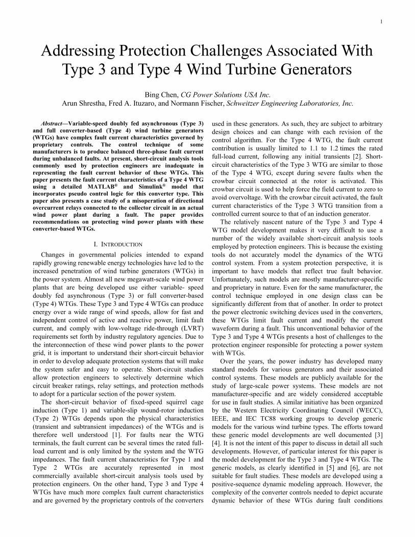
A. Case 1: Three-Phase Fault at WTG Terminal (Bus 3) The simulation starts with the WTG set at P priority (i.e.,
supplying active power to the grid). At t = 0.3 seconds, a balanced three-phase fault is applied at the WTG terminal. Fig. 7 shows the WTG instantaneous current and voltage. The fault current following the fault hardly increases beyond 1.1 pu, as expected of a Type 4 WTG.
1.51
0.50
–0.5–1
–1.5
1.51
0.50
–0.5–1
–1.50.2 0.25 0.3 0.35 0.4 0.45
0.2 0.25 0.3 0.35 0.4 0.45
Time (seconds)V
olta
ge (p
u)C
urre
nt (p
u)
IA IB IC
VA VB VC
Fig. 7. WTG pu current (top) and voltage (bottom) for a three-phase fault at Bus 3.
Fig. 8 shows the output of the current limit logic as a function of the WTG terminal voltage (Vterm). It can be seen from the graphs in Fig. 8 that as the terminal voltage decreases due to the fault, Ipmax decreases and Iqmax increases to provide the needed reactive power support to the grid. Idref and Iqref are the referenced active and reactive command signals provided to the converter controller. As shown in Fig. 8, the response of the controller stabilizes in about one power system cycle following the fault.
10.5
0
10.5
0
10.5
0
10.5
0
10.5
0
0.2 0.25 0.3 0.35 0.4
0.2 0.25 0.3 0.35 0.4
0.2 0.25 0.3 0.35 0.4
0.2 0.25 0.3 0.35 0.4
0.2 0.25 0.3 0.35 0.4
Vte
rmIp
max
Iqm
axId
ref
Iqre
f
Time (seconds)
Fig. 8. Output signals from current limit logic for a three-phase fault at Bus 3.
B. Case 2: Three-Phase Fault at the Collector Bus (Bus 2) In Case 2, a three-phase balanced fault is applied at the
collector bus, Bus 2. Fig. 9 shows the fault current contribution from the WTGs and the terminal voltage before and during the fault. Regardless of the line and transformer

5
impedances between the collector bus and WTG bus, the fault current magnitude is close to the fault current contribution observed during the three-phase balanced fault at the WTG terminals, as shown in Case 1. This illustrates the fact that Type 4 WTGs are operated as a controlled current source and the impedance between the generator and fault location has no effect on the fault current contribution. Hence, the conventional voltage-behind-the-impedance approach to calculate fault current does not apply to converter-based WTGs.
1.51
0.50
–0.5–1
–1.5
1.51
0.50
–0.5–1
–1.50.2 0.25 0.3 0.35 0.4 0.45
0.2 0.25 0.3 0.35 0.4 0.45
Time (seconds)
Vol
tage
(pu)
Cur
rent
(pu)
IA IB IC
VA VB VC
Fig. 9. WTG pu current (top) and voltage (bottom) for a three-phase fault at Bus 2.
The output of the current limit logic for the balanced three-phase fault at the collector bus is shown in Fig. 10. During the fault, Vterm decreases significantly and, as a result, Ipmax decreases and Iqmax increases. Therefore, the WTGs decrease their active power output and support the grid by supplying higher reactive power. Also, Idref and Iqref do not exceed the Ipmax and Iqmax limits.
10.5
0
10.5
0
10.5
0
10.5
0
10.5
0
0.2 0.25 0.3 0.35 0.4
0.2 0.25 0.3 0.35 0.4
0.2 0.25 0.3 0.35 0.4
0.2 0.25 0.3 0.35 0.4
0.2 0.25 0.3 0.35 0.4
Vte
rmIp
max
Iqm
axId
ref
Iqre
f
Time (seconds)
Fig. 10. Output signals from current limit logic for a three-phase fault at Bus 2.
C. Case 3: Single-Phase-to-Ground Fault at WTG Terminal (Bus 3)
The response of the Type 4 WTG to an unbalanced fault is shown in Fig. 11. A phase-to-ground fault is applied at the
WTG terminal at t = 0.3 seconds. As observed, the fault current does not change significantly relative to the prefault current. Even for a line-to-ground fault, the current from the WTG remains balanced. This is because an unbalanced fault would result in a significant ripple on the dc bus and therefore would require a larger capacitor. WTG manufacturers avoid using large capacitors that can accommodate the large ripple in the dc bus by forcing the current to be balanced. This ensures that the sum of the currents leaving the WTG at all times is zero (i.e., IA + IB + IC = 0). With the balanced current, the dc bus voltage is maintained during a fault. This control approach suppresses the negative-sequence current contribution from the WTG during unbalanced fault conditions, unlike conventional generators.
1
0
–1
1
0
–1
0.2 0.25 0.3 0.35 0.4 0.45
0.2 0.25 0.3 0.35 0.4 0.45
Time (seconds)
Vol
tage
(pu)
Cur
rent
(pu)
IA IB IC
VA VB VC
Fig. 11. WTG pu current (top) and voltage (bottom) for a single-phase-to-ground fault at Bus 3.
The output of the current limit logic is shown in Fig. 12. As shown, the WTG terminal voltage is reduced to about half its nominal value, thereby allowing for the continual supply of some amount of active and reactive power. However, the active power is reduced from its prefault state and the reactive power support to the grid is increased as expected. The fault current does not change significantly. Hence, the WTG barely contributed to the fault current.
10.5
0
10.5
0
10.5
0
10.5
0
10.5
0
0.2 0.25 0.3 0.35 0.4
0.2 0.25 0.3 0.35 0.4
0.2 0.25 0.3 0.35 0.4
0.2 0.25 0.3 0.35 0.4
0.2 0.25 0.3 0.35 0.4
Vte
rmIp
max
Iqm
axId
ref
Iqre
f
Time (seconds) Fig. 12. Output signals from current limit logic for a single-phase-to-ground fault at Bus 3.

6
D. Case 4: Single-Phase-to-Ground Fault at Collector Bus (Bus 2)
For this case, a similar unbalanced fault is applied at t = 0.3 seconds at Bus 2. The WTG fault voltage and current as well as the outputs of the current limit logic are shown in Fig. 13 and Fig. 14, respectively. Due to the delta-wye grounded connection of the pad-mounted transformer, a single-line-to-ground fault on the collector bus appears as a line-to-line fault to the WTG. Again, the fault current barely differs from that of Case 3 and is balanced for similar reasons, as explained previously. Once again, this verifies that the fault current contribution from the Type 4 WTG is independent of the impedance between the fault point and the WTG location.
1
0
–1
1
0
–1
0.2 0.25 0.3 0.35 0.4 0.45
0.2 0.25 0.3 0.35 0.4 0.45
Time (seconds)
Vol
tage
(pu)
Cur
rent
(pu)
IA IB IC
VA VB VC
Fig. 13. WTG pu current (top) and voltage (bottom) for a single-phase-to-ground fault at Bus 2.
10.5
0
10.5
0
10.5
0
10.5
0
10.5
0
0.2 0.25 0.3 0.35 0.4
0.2 0.25 0.3 0.35 0.4
0.2 0.25 0.3 0.35 0.4
0.2 0.25 0.3 0.35 0.4
0.2 0.25 0.3 0.35 0.4
Vte
rmIp
max
Iqm
axId
ref
Iqre
f
Time (seconds) Fig. 14. Output signals from current limit logic for a single-phase-to-ground fault at Bus 2.
IV. WIND POWER PLANT AND COLLECTOR CIRCUIT PROTECTION
A modern wind power plant consists of a large number of WTGs, a collector system, substation transformers, and transmission lines or cables that connect the wind power plant to the grid. Fig. 15 depicts a one-line diagram of a typical wind power plant with two collector circuits. Multiple WTGs are connected to the collector bus with the feeder circuit in a daisy-chain fashion. The WTGs are normally ungrounded and do not contribute significantly to the ground current during
unbalance faults. The ground current contribution that is likely to be produced is typically from the grounding transformer connected at the collector bus. WTGs usually operate at low voltage (usually 575 to 690 V) and connect to the collector feeder via pad-mounted transformers. Pad-mounted transformers are usually protected with fuses and occasionally have low-voltage breakers. Normally, these transformers are connected in a delta-wye grounded fashion to block the flow of zero-sequence current from the collector circuit to the WTGs. The collector circuit connects a group of WTGs to the collector bus via a series of either overhead lines or underground cables. The collector circuit is usually grounded with a grounding transformer. Substation transformers step up the collector voltage (around 13.8 to 34.5 kV) to the grid voltage for interconnection.
Protection of the station transformer and collector bus in existing wind power plants is similar to that of any distribution substation. The protection schemes for the station transformer and collector bus are somewhat standardized and are not discussed here. The challenge lies in protecting the collector circuits connected to the converter-based WTGs. The protection scheme for the collector circuit should be sensitive enough to detect faults at the lateral circuit of the farthest WTG and also provide backup protection of the WTG pad-mounted transformer. The protection scheme should be secure against transformer inrush current during collector circuit energization. The protection scheme should not misoperate during normal reactive power support or during faults and should not interfere with the LVRT requirements.
Sensitive phase directional overcurrent relays are often used to protect collector circuits. These relays are set to look into the WTG from the collector bus (opposite of normal power flow direction). To provide security against transformer inrush current, harmonic blocking can be used during circuit energization. A core-balanced current transformer (CT) at the collector circuit or current flowing through the grounding transformer can also be used for sensitive ground fault detection.
V. CASE STUDY OF MISOPERATION OF DIRECTIONAL OVERCURRENT RELAY AT COLLECTOR CIRCUIT
A section of a wind power plant located in the New York region is shown in Fig. 16. Only three collector circuits are shown for simplicity. All WTGs are Type 4 generators with a rated capacity of 2.5 MW each. There are four wind turbines on Feeders 7A and 7B and six wind turbines on Feeder 8A. The wind power plant substation is interconnected to the utility through two identical power transformers. The collector Buses A and B were connected during the case study event. The 13.8 kV collector Circuits 7A, 7B, and 8A are protected using the 11F7A, 11F7B, and 11F8A feeder overcurrent relays, respectively. Bus voltage is supplied to the relays using open-delta-connected voltage transformers. Directional overcurrent elements are set to look toward the WTGs. Negative-sequence voltage-polarized directional elements are used to supervise both phase and negative-sequence overcurrent elements.

7
Grid
Station Transformer
Collector Bus
Grounding Transformer
Collector Circuit
Pad-Mounted Transformer
WTG
...
...
Fig. 15. Simplified one-line diagram of a typical wind power plant.
UtilityPoint of
Interconnection 115 kV
115 kV
115
TX-1
117
Line A
1 2
Line BNormally Open Tie
115 kV
116
TX-2
118
Normally Open Tie13.8 kV
A B 13.8 kV
Closed During the
Event67
11F7A
CT7A500/5
CT8A500/5
F7A
67
11F8A
F8A
CT7B500/5
67
11F7B
F7B
Fig. 16. One-line diagram of a section of a wind power plant installed in the New York area.
8
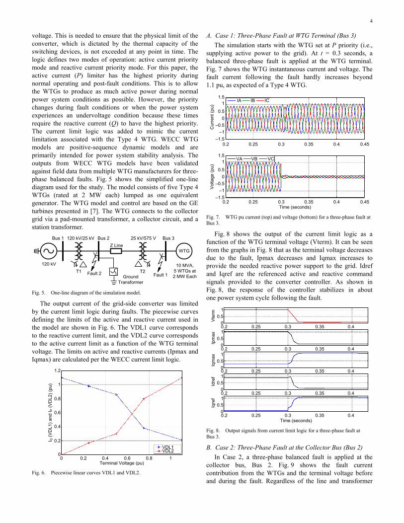
A BCG fault occurred at collector Circuit 7B. Relay 11F7B saw the fault as a normal forward fault and tripped Breaker F7B after a time delay. The instantaneous current and voltage signals and some of the protection bits that asserted during the event for Relay 11F7B are shown in Fig. 17. Because the fault was in the forward direction and due to the stiffness of the grid, large fault current flowed from the grid to the collector circuit. The relay identified the fault as a forward fault (forward directional elements 32GF, 32QF, and 32PF asserted), and the time-overcurrent element, 51P1T tripped the breaker.
Fig. 17. Raw event report from Relay 11F7B for a BCG fault at the F7B collector circuit.
The vector diagram of the sequence components for prefault and during the fault for Relay 11F7B is shown in Fig. 18. The prefault vector diagram shows that the normal power flow direction is opposite to that of the relay set direction. Because the fault current seen by Relay 11F7B is supplied by the grid, which is highly inductive, positive-sequence current (I1) lags positive-sequence voltage (V1) and negative-sequence current (I2) leads negative-sequence voltage (V2). The negative-sequence voltage-polarized directional elements determine the fault direction by calculating negative-sequence impedance (Z2) using (1).
( )( )*
2 22 2
2
Re V • I •1 Z1ANGZ
I
∠= (1)
9060
30
0
330
300270
240
210
180
150
12090
60
30
0
330
300270
240
210
180
150
120
I1 V1
I2
V2
V1
I1
Fig. 18. Vector diagram of sequence components for Relay 11F7B (prefault on the left and during fault on the right).
A forward fault direction is declared if Z2 is less than the forward directional threshold, and a reverse directional fault is
declared if Z2 is greater than the reverse directional threshold. If we consider the angle between V2 and I2, a forward fault is declared if I2 leads V2 and a reverse fault is declared if I2 lags V2 in an inductive power system.
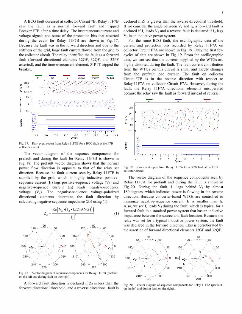
For the same BCG fault, the oscillographic data of the current and protection bits recorded by Relay 11F7A on collector Circuit F7A are shown in Fig. 19. Only the first few cycles of data are shown in Fig. 19. From the oscillographic data, we can see that the currents supplied by the WTGs are highly distorted during the fault. The fault current contribution from the WTGs on this circuit is small and hardly changes from the prefault load current. The fault on collector Circuit F7B is in the reverse direction with respect to Relay 11F7A on collector Circuit F7A. However, during the fault, the Relay 11F7A directional elements misoperated because the relay saw the fault as forward instead of reverse.
Fig. 19. Raw event report from Relay 11F7A for a BCG fault at the F7B collector circuit.
The vector diagram of the sequence components seen by Relay 11F7A for prefault and during the fault is shown in Fig. 20. During the fault, I1 lags behind V1 by almost 180 degrees, which indicates power is flowing in the reverse direction. Because converter-based WTGs are controlled to minimize negative-sequence current, I2 is smaller than I1. Also, we see I2 leads V2 during the fault, which is typical for a forward fault in a standard power system that has an inductive impedance between the source and fault location. Because the relay was set for a typical inductive power system, the fault was declared in the forward direction. This is corroborated by the assertion of forward directional elements 32GF and 32QF.
9060
30
0
330
300270
240
210
180
150
12090
60
30
0
330
300270
240
210
180
150
120
I1V1
I2V2
V1I1
Fig. 20. Vector diagram of sequence components for Relay 11F7A (prefault on the left and during fault on the right).

9
This misoperation of the directional element can be attributed to the attempt of the WTG converter control to balance the output fault current in all three phases. The converter control caused the system behind the relay to become capacitive instead of inductive. Relay 11F8A directional elements also misoperated during the event as this relay also saw the fault as forward. The event report of Relay 11F8A is similar to that of Relay 11F7A and is therefore not shown.
From Fig. 20, it can be seen that the negative-sequence current (I2) leads the voltage (V2) by approximately 60 degrees, which is similar to a reverse resistive fault on a capacitive system. As mentioned previously, the relay was set for a conventional power system with a line angle close to 90 degrees (the impedance behind the relay was used to determine this setting; in this case, it was a power transformer). Substituting the values of V2, I2, and Z1ANG from Fig. 20 into (1) results in a negative Z2 value. A negative Z2 value translates into a forward fault direction.
To correct for the misoperation of the negative-sequence directional element in this case, the positive-sequence line angle (Z1ANG) has to be set at a low value, typically 10 degrees. If Z1ANG was set at 10 degrees for this case, the modified I2 quantity would have led V2 by 70 degrees, which would have resulted in a positive Z2 value, translating into a reverse fault direction. In general, a true forward fault would result in I2 leading V2 by about 120 degrees because the source behind the relay for such a fault is a conventional power system. Applying a setting of Z1ANG of 10 degrees would therefore have no negative impact on the directionality of the negative-sequence directional element for an unbalanced forward fault. For a balanced fault, a positive-sequence voltage-polarized directional element is used and will not be affected by the low Z1ANG value.
A similar misoperation of the directional overcurrent elements with WTGs operated in voltage control mode is presented in [14]. Similarly, in this case, the positive-sequence line angle (Z1ANG) had been set for a normal conventional power system (70 degrees and above), and because of this, the negative-sequence directional element misoperated. A lower value of Z1ANG would have corrected this problem.
VI. CONCLUSION Short-circuit characteristics of Type 3 and Type 4 WTGs
are very complex and are governed by the proprietary control of the converters used by each manufacturer. A detailed GE Type 4 WTG model with WECC current limit logic was simulated in MATLAB and Simulink to study the behavior of converter-based WTGs during balanced and unbalanced faults. As verified, the Type 4 WTG behavior during these fault types is not distinct and the fault current magnitudes barely increase above the full-load current. Also, the challenges posed by converter-based WTGs to the directionality of overcurrent relays are discussed through an actual field event report. The distortion in fault signals coupled with the change in the angle difference between the fault voltage and current sometimes affects the ability of
existing protective relays to identify the correct fault direction. Considering that directional elements are used to supervise a number of other protection elements, they pose a significant risk to the reliability of the power system if they misoperate. Directional overcurrent elements can be supervised with load encroachment logic to help prevent this. However, in the future, a collaborative effort should be pursued between relay manufacturers and WTG manufacturers so that better directional protection algorithms can be developed to protect systems with Type 3 and Type 4 WTGs. Line current differential relaying with pilot protection schemes should also be considered for wind power plant systems because they would be unaffected by the WTG control algorithms and inherently secure. While more expensive than overcurrent relays, the cost of such schemes is arguably insignificant when compared with the value of the lost generation and system stability as wind power plant output increases. Also, there is a need for generic models for these WTGs that can be used by protection engineers for fault analysis. This will help in the choice of relay type and settings and ultimately protect the large economic investment associated in developing wind power plants.
VII. REFERENCES [1] E. Muljadi, N. Samaan, V. Gevorgian, J. Li, and S. Pasupulati, “Short
Circuit Current Contribution for Different Wind Turbine Generator Types,” proceedings of the IEEE Power and Energy Society General Meeting, Minneapolis, MN, July 2010.
[2] R. J. Nelson and H. Ma, “Short-Circuit Contributions of Full-Converter Wind Turbines,” proceedings of the IEEE Power and Energy Society General Meeting, San Diego, CA, July 2011.
[3] A. Ellis, Y. Kazachkov, E. Muljadi, P. Pourbeik, and J. J. Sanchez-Gasca, “Description and Technical Specifications for Generic WTG Models – A Status Report,” proceedings of the IEEE Power and Energy Society Power Systems Conference and Exposition, Phoenix, AZ, March 2011.
[4] WECC Renewable Energy Modeling Task Force, “WECC Wind Power Plant Dynamic Modeling Guide,” November 2010. Available: http://www.wecc.biz/.
[5] P. Pourbeik, “Proposed Changes to the WECC WT3 Generic Model for Type 3 Wind Turbine Generators,” January 2013. Available: http://www.wecc.biz/.
[6] P. Pourbeik, “Proposed Changes to the WECC WT4 Generic Model for Type 4 Wind Turbine Generators,” January 2013. Available: http://www.wecc.biz/.
[7] N. W. Miller, J. J. Sanchez-Gasca, W. W. Price, and R. W. Delmerico, “Dynamic Modeling of GE 1.5 and 3.6 MW Wind Turbine-Generators for Stability Simulations,” proceedings of the IEEE Power Engineering Society General Meeting, Toronto, Canada, July 2003.
[8] K. Clark, N. W. Miller, and J. J. Sanchez-Gasca, Modeling of GE Wind Turbine-Generators for Grid Studies, Version 4.5. General Electric International, Inc., Schenectady, NY, 2010.
[9] R. A. Walling, E. Gursoy, and B. English, “Current Contributions From Type 3 and Type 4 Wind Turbine Generators During Faults,” proceedings of the IEEE Power and Energy Society General Meeting, San Diego, CA, July 2011.
[10] M. B. C. Salles, K. Hameyer, J. R. Cardoso, A. P. Grilo, and C. Rahmann, “Crowbar Systems in Doubly Fed Induction Wind Generators,” Energies, Vol. 3, Issue 4, April 2010, pp. 738–753.
[11] J. Morren and S. W. H. de Haan, “Short-Circuit Current of Wind Turbines With Doubly Fed Induction Generator,” IEEE Transactions on Energy Conversion, Vol. 22, Issue 1, March 2007, pp. 174–180.

10
[12] United States of America Federal Energy Regulatory Commission, “Interconnection for Wind Energy,” Order No. 661, 18 CFR Part 35, June 2005. Available: http://www.ferc.gov/whats-new/comm-meet/052505/E-1.pdf.
[13] MathWorks, “Wind Farm – Synchronous Generator and Full Scale Converter (Type 4) Detailed Model.” Available: http://www.mathworks.com/help/physmod/powersys/examples/wind-farm-synchronous-generator-and-full-scale-converter-type-4-average-model.html.
[14] D. Jones and K. Bennett, “Wind Farm Collector Protection Using Directional Overcurrent Elements,” proceedings of the 2012 IEEE Power and Energy Society Transmission and Distribution Conference and Exposition, Orlando, FL, May 2012.
VIII. BIOGRAPHIES Bing Chen received his BS and MS in Electrical Engineering from Shandong University in 1994 and 1997, respectively, and earned his second MS in Electrical Engineering from the University of Toledo in 2001. He began his career working as a substation engineer at Shandong Electrical Power Consulting Institute. Following his graduate study at the University of Toledo, he served three years as an electrical engineer at GE Industrial Systems and Bechtel Power Corporation. In 2004, he joined CG Power Solutions USA Inc., formerly known as MSE Power Systems, Inc., as a protection engineer. He presently serves as the lead protection engineer for CG Power Solutions USA Inc. in the Maryland office. He has performed over 100 different power system studies and provided detailed relay settings for several dozen substation and wind farm projects. Bing is a registered Professional Engineer in the states of Maryland, Washington, Wisconsin, Maine, Minnesota, and Arizona.
Arun Shrestha received his BS in Electrical Engineering from the Institute of Engineering, Tribhuvan University, Nepal, in 2005 and his MSEE from the University of North Carolina at Charlotte in 2009. At present, he is working as a power engineer in the research and development division at Schweitzer Engineering Laboratories, Inc.. He is also actively pursuing his PhD in electrical engineering at the University of North Carolina at Charlotte. His research areas of interest include wide-area protection and control, real-time power system modeling and simulation, and power system stability.
Fred Agyekum Ituzaro received his BSc in Electrical/Electronic Engineering, with honors, from Kwame Nkrumah University of Science and Technology, Ghana, in 2008 and his MSc degree in electrical engineering from Texas A&M University in 2012. He is currently an associate power engineer at Schweitzer Engineering Laboratories, Inc. Prior to that, he was a research assistant at the Texas A&M Power System Automation Laboratory. His research interests include distributed generation integration studies, power system protection, and microprocessor-based relay design. Fred is a member of IEEE Power and Energy Society.
Normann Fischer received a Higher Diploma in Technology, with honors, from Technikon Witwatersrand, Johannesburg, South Africa, in 1988; a BSEE, with honors, from the University of Cape Town in 1993; and an MSEE from the University of Idaho in 2005. He joined Eskom as a protection technician in 1984 and was a senior design engineer in the Eskom protection design department for three years. Normann then joined IST Energy as a senior design engineer in 1996. In 1999, he joined Schweitzer Engineering Laboratories, Inc. as a power engineer in the research and development division. Normann was a registered professional engineer in South Africa and a member of the South African Institute of Electrical Engineers. He is currently a member of IEEE and ASEE.
Previously presented at the 2015 Texas A&M Conference for Protective Relay Engineers.
© 2015 IEEE – All rights reserved. 20150210 • TP6626-01