additive manufacturing cost and lead time estimation...
TRANSCRIPT

1
Degree Project in Production Engineering and Management (MG213X)
ADDITIVE MANUFACTURING Cost and Lead Time Estimation, Benefits and Challenges
MARYIA SIDORYK
MARAN TIROUGNANASSAMBANDAMOURTY

2
ABSTRACT
Additive manufacturing (AM) is one of the most widely explored technology in the field of manufacturing in recent years. With a rapid development in its process elements such as process speed, dimensional accuracy, surface finish and repeatability, additive manufacturing continues to expand from being a prototyping technology to substituting the conventional manufacturing processes. Like many organizations, which are trying to investigate the economic benefits of adopting AM, Scania wants to study the costs of adopting AM to manufacture parts for its special products division. This study involves costs and lead time estimation, benefits and challenges of adopting AM to manufacture the given case study parts from Scania. The most suitable AM technology to manufacture these case studies is chosen by studying various AM technologies available in the market. The chosen AM technology is Electron Beam Melting (EBM). Simulations are done to estimate the build time of manufacturing these parts using EBM platform. It is also used to estimate the production costs using a suitable cost model and parts lead time. The results are compared to those of traditional manufacturing process. Further to this, benefits and challenges of adopting AM in the context of low volume production and supply chain challenges are also studied. In the cost comparison exercise, it was found that with the current state of technology, cost of manufacturing through AM is roughly four times that of traditional manufacturing processes. However, the lead times corresponding to AM is just a fraction of those corresponding to traditional manufacturing supply chain. It can be concluded that it would not be economical to manufacture the case study parts through AM. However, from further research it was realised that it is important to take advantage of the capabilities of AM to be able to attain an economic advantage over traditional processes from the perspective of their supply chain complexity. One such option is to use Design for Additive Manufacturing (DfAM) to optimise the design of the case study parts to incorporate AM’s part consolidation capabilities thus simplifying the supply chains and shortening the lead time significantly. This study is a good starting point for Scania to explore AM as an alternative manufacturing process. Further study in terms of DfAM can provide a conclusive result on the adoption of AM.

3
SAMMANFATTNING
Additive manufacturing (AM) är en av de mest utforskade teknologierna inom tillverkningsområdet de senaste åren. Med sin snabba utveckling i processelementen, såsom processhastighet, dimensionsnoggrannhet, ytfinish, repeterbarhet, tillsatsframställning fortsätter att expandera från att vara en prototypteknik för att ersätta de konventionella tillverkningsprocesserna. Liksom många organisationer som försöker undersöka de ekonomiska fördelarna med att använda AM, vill Scania studera kostnaderna för att anta AM för att tillverka delar för sin speciella produktavdelning. Denna studie innehåller kostnader och ledtidsestimering, fördelar och utmaningar att övergå till AM för att tillverka delarna som fås från Scania för detta studiefall. Den mest lämpliga AM-tekniken för att tillverka dessa fallstudier är vald genom att studera de olika AM-teknologier som finns tillgängliga på marknaden. Den valda AM-teknikem är Electron Beam Melting (EBM). Simuleringar görs för att uppskatta byggtiden för tillverkningen av dessa delar genom att använda EBM-tekniken. Detta används vidare för att uppskatta produktionskostnaderna med hjälp av en lämplig kostnadsmodell och ledtid i produktionen av delarna. Resultaten jämförs med traditionell tillverkningsprocess. Vidare studeras fördelar och utmaningar för att anta AM i samband med lågvolymproduktion och försörjningskedjans utmaningar. I kostnadsutjämningsövningen konstaterades att tillverkningskostnaden med den nämnda AM telniken är ungefär fyra gånger högre än traditionella tillverkningsprocesser. De ledtider som motsvarar AM är bara en bråkdel av dem som motsvarar traditionell tillverkningskedja. Sammanfattninsvis kan man dra att det inte skulle vara ekonomiskt att tillverka dessa delar genom AM. Samtidigt inser man vikten av att utnyttja AM tekniken för att kunna uppnå en ekonomisk fördel gentemot komplexiteten i utbudskedjan av de traditionella processerna. Ett sådant alternativ är att använda Design for Additive Manufacturing (DfAM) för att optimera utformningen av fallstudier för att införliva AMs delkonsolideringskapacitet, vilket förenklar försörjningskedjorna och förkortar ledtiden avsevärt. Denna studie är en bra utgångspunkt för Scania att utforska AM som en alternativ tillverkningsprocess. Ytterligare studier i form av DfAM kan ge upphov till ett avgörande resultat vid valett av AM.

4
ACKNOWLEDGEMENTS
We are grateful to KTH, specially Amir Rashid for giving us the opportunity to perform
our thesis in the topic that interested us the most. We thank Amir for his long
discussions on the topic, giving feedbacks and for helping us to get in touch with
industry contacts.
We would also like to thank Xiaoyu Zhao for help us with simulating the build processes
in the AM machine and for clarifying our doubts on the topic.
Furthermore, we would like to thank Johan Nordkvist and Magnus Mistander of Scania
for providing valuable information and supporting us with data and feedback. This
thesis would not be possible without their collaboration.
We would also like to extend our gratitude to AIM Sweden for helping us with simulation
process. We appreciate their support.
We would also like to extend our gratitude to our family and friends for supporting us.

5
TABLE OF CONTENTS
1 INTRODUCTION .............................................................................................................. 7
1.1 BACKGROUND ........................................................................................................ 7
1.2 STATEMENT (RESEARCH QUESTIONS) ............................................................ 8
1.3 SCOPE OR DELIMITATION ................................................................................... 8
1.4 CURRENT SCENARIO ............................................................................................ 9
1.5 METHODOLOGY ................................................................................................... 10
2 LITERATURE REVIEW ................................................................................................. 11
2.1 INTRODUCTION TO AM ...................................................................................... 11
2.2 AM TECHNOLOGIES ............................................................................................ 12
2.2.1 VAT PHOTOPOLYMERIZATION ................................................................ 12
2.2.2 POWDER BED FUSION ................................................................................. 13
2.2.3 MATERIAL EXTRUSION .............................................................................. 15
2.2.4 MATERIAL JETTING .................................................................................... 17
2.2.5 BINDER JETTING .......................................................................................... 18
2.2.6 DIRECT ENERGY DEPOSITION .................................................................. 19
2.2.7 SHEET LAMINATION ................................................................................... 20
3 COST AND LEAD TIME ESTIMATION ...................................................................... 22
3.1 ELECTRON BEAM MELTING ............................................................................. 23
3.2 EBM SYSTEM ........................................................................................................ 24
3.3 SIMULATION ......................................................................................................... 26
3.4 COST MODEL ........................................................................................................ 27
3.5 COST AND LEAD TIME CALCULATION .......................................................... 27
3.5.1 Final results ...................................................................................................... 27
4 ADANTAGES AND CHALLENGES OF AM ............................................................... 30
4.1 ADVANTAGES OF AM ......................................................................................... 30
4.1.1 Design for Additive Manufacturing (DfAM) ................................................... 31
4.1.2 Product and process design .............................................................................. 32
4.1.3 Material input processing ................................................................................. 33
4.1.4 Make-to-order components and product manufacturing .................................. 34
4.1.5 Closing the loop ............................................................................................... 34
4.2 SUPPLY CHAIN ..................................................................................................... 35
4.2.1 Monitory Cost Perspective ............................................................................... 35
4.2.2 Resource consumption perspective .................................................................. 37

6
4.2.3 Lead Time Benefits .......................................................................................... 41
4.3 ECONOMIES OF SCALE ....................................................................................... 42
4.4 CHALLENGES AND RISKS .................................................................................. 43
4.5 BUSINESS MODEL ................................................................................................ 44
5 DISCUSSION AND CONCLUSIONS ............................................................................ 45
5.1 FUTURE OF AM IN SCANIA ................................................................................ 45
5.2 FUTURE OF AM IN MANUFACTURING ........................................................... 46
6 REFERENCES ................................................................................................................. 49
7 Appendix 1 ....................................................................................................................... 54
8 Appendix 2 ....................................................................................................................... 55
7
1 INTRODUCTION
1.1 BACKGROUND
As mass production is being transferred to developing countries, western countries
must switch towards low volume production with high added value through innovative,
customized and sustainable products. To compete in such competitive environment,
manufacturers have started to look for new manufacturing techniques which have
higher flexibility and can give low volume production in an economical way. One such
technique is additive manufacturing, better known as 3D printing and is being promoted
as the start of new industrial revolution (Weller et al., 2015).
AM industry was valued at 3 billion US dollars, and is expected to rise to 13 billion US
dollars by 2018, 21 billion US dollars by 2020 (Wohlers, 2014). With such enormous
potential, many industries have started to explore and adopt AM technologies. Though
having been known for a few decades now, AM techniques have been predominately
limited to manufacturing of prototypes. However recent advancements in the
technology specifically speed, part quality and performance have made it possible to
adopt the technology in conventional manufacturing. Nowadays, it has become
feasible to reliably manufacture dense parts in certain AM techniques and with various
material, including steel, aluminium and titanium (Murr et al., 2012). Manufacturers in
domains such as automobile, dental, biomedical and aerospace have already
successfully adopted AM techniques. The flexibility of AM insures that parts can be
customized, allows for digital interaction with customers, which in turn helps to reduce
costs, supply chain complexity and lead times (Bogers et al., 2016).
With such enormous potential like easy customization and personalization of products
and production, AM provides the opportunities and challenges to develop new
business models – the logic of creating and capturing value (Pillers et al., 2015;
Ponfoort et al., 2014).
The thesis is being performed at the department of Special Vehicles at Scania which
deals with customized products. This means the production volume is low and the
product design is highly variable. In other words, producing these parts through the

8
conventional manufacturing methods can be economical only in large quantities.
However, this in turn increases the storage costs. To avoid this, the company is looking
for other flexible manufacturing techniques which can be economical for low volume
production. In this thesis, AM is being explored to better understand its capabilities and
opportunities.
1.2 STATEMENT (RESEARCH QUESTIONS)
What are the costs and lead time of manufacturing the case study parts through
additive manufacturing and what are the benefits of doing so?
Below sub-questions can be derived from the research question above:
- What are the available types of AM technologies?
- Which of these technologies would be most suitable for the given parts?
- What is the most suitable cost model to evaluate AM?
- What are the advantages and challenges of adapting AM at the company?
- What are the effects of AM on the design and supply chain of the parts?
- What is the future of AM in manufacturing industry?
1.3 SCOPE OR DELIMITATION
The study is performed considering the three case study parts provided by the
company. These parts represent majority of the parts purchased by the department of
the company. The costs and lead time are calculated for these case studies through
the chosen cost model. The costs and lead time study is done considering the chosen
AM technology. The study does not include the comparison of mechanical properties
as well as design improvements suggestion for AM adoption. The research includes
effects of AM adoption on the supply chain and design process at the company. The
future of AM in manufacturing industry is explored briefly.

9
1.4 CURRENT SCENARIO
The company purchases its parts from suppliers who manufactures them through
conventional processes. Since these are low volume parts, economies of scale cannot
be achieved and hence the part cost is high. Lead times are also high due to complex
logistics. This thesis considers three parts which is assumed to represent the majority
of the parts bought from the supplier. The details about the parts can be found in the
table 1 – Details of case studies.
Part No Part 1 Part 2 Part 3
Material Aluminium EN AC-46000
DF, EN AC-Al Si9Cu3(Fe) Aluminium EN AC-46000 DF, EN AC-Al
Si9Cu3(Fe) Steel S355MC
Unit Cost 250 euro 117 euro 35 euro
Lead Time 14 weeks 12 weeks 8 weeks
Consumption 50 pcs/year 50 pcs/year 50 pcs/year
Manufacturing Method
Casting Sheet metal cutting, bending,
welding Sheet metal cutting and
bending
Build Size 195 mm x 270 mm x 175
mm 173 mm x 244 mm x 150 mm 350 mm x 168 mm x 73 mm
Table 1 Details of case studies
Two of these parts are made from aluminium and the other one is made of steel.
Presently, these parts are manufactured by conventional manufacturing processes
such as casting, bending, cutting etc. Aiming to reduce part costs and to increase part
design variability, this thesis explores AM as an option.

10
1.5 METHODOLOGY
The various AM technologies available in the market are studied through literature
review and the most suitable technique is chosen from it. The cost model to calculate
the manufacturing cost is chosen from literature review. The suitable AM system is
chosen from market study. The build simulation of the case studies is done in the
chosen AM system with the help of a research institute in Sweden. Conclusions from
the results are made with the help of simulations and calculation results including the
literature review.
This thesis report is organised as follows: subsequent to the introduction, Section 2
presents the literature review done for the study. Section 3 outlines the steps which
lead to the cost and lead time estimation. A details explanation of the advantages and
challenges is discussed in Section 4. Conclusions are drawn and recommendations
for further research are expressed in Section 5

11
2 LITERATURE REVIEW
2.1 INTRODUCTION TO AM
Additive manufacturing is defined by ASTM (2012) as “joining materials to make
objects from 3D model data, usually layer upon layer, as opposed to subtractive
manufacturing methodologies”. Also known as 3D printing or rapid prototyping, this
technology is gaining immense attention due to its ability to improve part functionality
with complex geometrical designs and along with the fact that it is theoretically possible
to produce any shape without limitations. (Gokuldoss et al., 2017) Unlike conventional
manufacturing where material is removed to make the product, AM involves additional
material to create a product.
The history of AM started in the field of rapid prototyping and then tooling. Though
these fields continue to be exploited, improvements in AM technologies have led to
them being used extensively in direct manufacturing. (Ford et al., 2016). AM
technology can produce customized products without tools or molds which helps in
cost reduction. Moreover, AM helps to produce complex and integrated functional
designs in a single step which can possible lead to reduction of assembly work. (Weller
et al., 2015)
The basic principle of this technology is that a part whose design is initially created in
a CAD system can be directly fabricated without a need for process planning. Though
it is not as simple as it sounds, AM technology has significantly simplified the
manufacturing of parts from CAD data. AM avoids the needs for the careful analysis of
part geometry to determine things such as the order of fabrication of different features,
the type of tools and processes, and the need for fixtures. This helps AM to be more
cost-effective technique than conventional manufacturing processes. (Gibson et al.,
2010)

12
2.2 AM TECHNOLOGIES
There are several variants of AM techniques that exist. These types differ in terms of
the raw material used and the technical principles behind the technique of layer
deposition, which gradually builds up three-dimensional parts. (Baumers et.al., 2016)
Choosing the right additive manufacturing process for a particular design is not always
an easy task. Availability of various types of AM techniques and materials means that
often several processes can be suitable. However, each of them can offer different
dimensional accuracies, surface finishes or post processing requirements. The various
types of AM technologies available in the market are:
2.2.1 VAT PHOTOPOLYMERIZATION
Vat photopolymerization is the process in which a photopolymer resin is solidified by
exposing it to light of a specific wavelength and inducing a chemical reaction. Various
AM technologies utilize this concept to make solid parts layer-by-layer. (3dhubs.com,
2017)
As the process uses liquid to form objects, there is no structural support from the
material during the build phase, unlike powder based methods, where support is given
from the unbound material. In this case, support structures will often need to be added.
Resins are cured using a process of photo polymerisation. (Gibson et al., 2010) The
light is directed across the surface of the resin with the use of motor controlled mirrors
(Grenda, 2009). When the resin comes in contact with the light, it cures or hardens.
Figure 1 Vat photopolymerization process (lboro.ac.uk, 2017)

13
Once the CAD data is transferred to the machine, the build platform lowers into the
VAT resin by the layer thickness. UV-light is directed across the surface of the resin by
use of motor controlled mirrors, which cures the resin layer-by-layer, solidifying it in the
process. The platform continues to lower and additional layers are built on top of
previous ones. After the completion of the process, the resin is drained and part is
removed.
Types: Stereolithography (SLA) - cured with laser, Digital Light Processing (DLP) –
cured with projector, Continuous Digital Light Processing (CDLP) – cured with LED
and oxygen.
Materials: plastic and polymers.
Though this process has high level of accuracy and good finish, it is relatively
expensive and often requires lengthy post processing and post curing for the parts to
be strong enough for structural use. Also, vat photopolymerization is relatively quick
process with large build areas. (lboro.ac.uk, 2017)
2.2.2 POWDER BED FUSION
Power bed fusion technology uses a thermal source to cause fusion between powder
particles one layer at a time and to produce a solid part. Powder bed fusion (PBF)
methods use either a laser or electron beam to melt and fuse material powder together.
Electron beam melting (EBM), methods require a vacuum but can be used with metals
and alloys in the creation of functional parts. All PBF processes involve the spreading
of the powder material over previous layers. There are different mechanisms to enable
this, including a roller or a blade. A hopper or a reservoir below or aside the bed
provides fresh material supply. Direct metal laser sintering (DMLS) is the same as SLS,
but with the use of metals and not plastics. The process sinters the powder, layer by
layer. Selective Heat Sintering differs from other processes by way of using a heated
thermal print head to fuse powder material together. As before, layers are added with
a roller in between fusion of layers. A platform lowers the model accordingly.
(3dhubs.com, 2017)

14
Figure 2 Powder bed fusion process (lboro.ac.uk, 2017)
The process begins with spreading layer of the powder material over the build platform.
A thermal source fuses the first cross section of the model over this thin layer of
material. A new powder layer is spread across the previously fused layer using a roller.
The process continuous until the complete model is made.
The main difference in PBF technologies is due to the variety in energy sources (laser
or electron beam) and the powder material used (plastic or metals).
Types: Multi Jet Fusion (MJF) – fused with agent and energy using plastic powder
materials, Selective Laser Sintering (SLS) – fused with laser using plastic powder
materials, Direct Metal Laser Sintering (DMLS) or Selective Laser Melting (SLM) –
fused with laser using metal powder materials, Electron Beam Melting (EBM) – fused
with electron beam using metal powder materials.
This is quite inexpensive method with large range of material options. However, the

15
process itself is relatively slow with high powder usage and a finish which is dependent
on the powder grain size. (lboro.ac.uk, 2017)
2.2.3 MATERIAL EXTRUSION
Material extrusion is the process in which material is heated and drawn through a
nozzle, and then deposited over the build platform one layer over another. The quality
of the final model depends on various factors, however there is great potential and
viability when these factors are controlled efficiently. (Gibson et al., 2010)
The nozzle can move horizontally and a platform moves up and down vertically after
each new layer is deposited. It is a commonly used technique used on many
inexpensive, domestic and hobby 3D printers. The process has many factors that
influence the final model quality but has great potential and viability when these factors
are controlled successfully. Whilst FDM is similar to all other 3D printing processes, as
it builds layer by layer, it varies in the fact that material is added through a nozzle under
constant pressure and in a continuous stream. This pressure must be kept steady and
at a constant speed to enable accurate results. (Gibson et al., 2010) Material layers
can be bonded by temperature control or through the use of chemical agents. Material
is often added to the machine in spool form as shown in Figure 3 - Material extrusion
process.

16
Figure 3 Material extrusion process (lboro.ac.uk, 2017)
As material is heated and passes through the nozzle it is deposited over the build
platform. Following layers are added on top of previous layers as per model cross
section. The layers are fused together by temperature control or by chemical agents.
There is also provision for the deposition of support materials to build support
structures.
Types: Fused Deposition Modelling (FDM).
Materials: Composites and plastic.
Being an inexpensive and user-friendly process, it is one of the most widely used AM
technology. However, when compared to other processes, the accuracy and process
speed are low. The quality of the final product is limited to material nozzle thickness
and consistency in the nozzle pressure. (lboro.ac.uk, 2017)

17
2.2.4 MATERIAL JETTING
Material jetting is the process in which parts are created by depositing photopolymers
layer-by-layer on a platform and curing or hardening them by exposing them to light or
high temperature. The process is often compared to 2D ink jetting process. This
principle allows the printing of different materials simultaneously and this helps to print
support structures from different material. The material is deposited on the build
platform either by a continuous or Drop on Demand (DOD) approach. The fact that
materials are deposited in drops limits the number of suitable materials.
Figure 4 Material jetting process (lboro.ac.uk, 2017)
The print head which deposits the materials is positioned right above the build platform.
Using thermal or piezoelectric method, the print head deposits droplets of material onto
the surface where required. Once deposited, the droplets solidify and form the first
layer. Further layers are built upon the previous layer, which eventually forms the parts.
Layers are hardened either by allowing it to cool down or curing it by UV-light. Supports
material is removed during the post processing.
Types: Material Jetting (MJ) – cured with UV light, NanoPartical Jetting (NPJ) – cured
with heat, Drop on Demand (DOD) – milled to form.
Materials: Plastic, metal and wax.

18
The process generates lower waste since it benefits from high accuracy of droplets
deposition. Multiple material parts and colours can be created under a single process.
Though the process gives the high accuracy, materials are limited to polymers and
waxes. (lboro.ac.uk, 2017)
2.2.5 BINDER JETTING
Binder jetting process uses powder material and liquid binder to build solid parts layer-
by-layer. The binder acts as an adhesive between the powder layers. Both powder
material and binder are deposited on the build platform using a print head. The print
head moves along the build platform depositing alternative layers of powder material
and the binder. Once a layer has been printed, the platform lowers and a new layer is
printed over the previous one. The process is repeated to generate a solid part. Once
a part is cured, it is removed from the powder bed, followed by post processing.
Figure 5 Binder jetting process (lboro.ac.uk, 2017)
Types: Binder Jetting (BJ) – joined with binding agent.
Materials: Metals, polymers and ceramics.
A major advantage of this process is the ability of the nozzle to contain colour which
helps to print complex geometric with different colours. Since binding is involved, the
material characteristics of parts made through binder jetting are not suitable for
structural parts and despite the relatively high printing speeds, need for post

19
processing leads to increase in the overall process time. (lboro.ac.uk, 2017)
2.2.6 DIRECT ENERGY DEPOSITION
Direct energy deposition is the process of building a part by melting material which is
in the form of powders or wire as it is deposited. This method is also known as direct
metal deposition. This process is mostly used in repair applications or to add additional
material to an existing component. (Gibson et al., 2010) Though the process typically
uses metals in the form of powder or wire, it can also be used with polymers and
ceramic materials.
Figure 6 Direct energy deposition process (lboro.ac.uk, 2017)
Build material either in the form of powder or wire is deposited on the build platform
through a nozzle. On deposition, the material is melted using a laser, plasma arc or
electron beam. Further layers of material are deposited on the previous ones upon
solidifying. The process is similar to material extrusion in principle. However, in this
method the nozzle is movable in multiple axes and it is not constrained to any specific
axis.
Types: Laser Engineering Net Shape (LENS) – fused with laser, Electron Beam
Additive Manufacturing (EBAM) – fused with electron beam.
Materials: metals, polymers and ceramics.
The processes are often used for repair works of high quality, functional parts, due to

20
high degree of control over the grain structure. The process often requires a balance
between speed and surface quality. However, speed is often sacrificed for a high
accuracy and predetermined microstructure in repair applications. (lboro.ac.uk, 2017)
2.2.7 SHEET LAMINATION
Sheet lamination is a process in which sheets or ribbons are bound together. Ultrasonic
Additive Manufacturing (UAM) is a sheet lamination process which uses metal sheets
or ribbons which are bound together using ultrasonic welding. UAM often requires post
processing which involves CNC machining to remove unbound material. Laminated
Object Manufacturing (LOM) is similar in principle to UAM but uses paper as material
and uses adhesive for bonding.
The method is often used to create aesthetic and visual models which are not suitable
for structural purpose.
Figure 7 Sheet lamination process (lboro.ac.uk, 2017)
The first sheet of material is placed on the cutting bed. The following material sheet is
fused over the previous one by ultrasonic welding or adhesive. The required cross-
sectional shape is cut from the layer by laser or knife. The next layer is placed and the
process is repeated until the part is created.
Types: Ultrasonic Additive Manufacturing (UAM) – metals fused with ultrasonic
welding, Laminated Object Manufacturing (LOM) – paper fused with adhesive.

21
Materials: Metals, composites and paper.
Though the process is fast, involves low costs and easy material handling, the strength
of the models relies on the adhesive used (Krar and Gill, 2003). The process uses
relatively low energy since the metal is not melted. The final product often requires
post processing to achieve the desired effect. (lboro.ac.uk, 2017)

22
3 COST AND LEAD TIME ESTIMATION
From the literature review, it is clear that the following techniques of AM can be used
to create metal parts:
1. Material Jetting
i. NanoParticle Jetting (NPJ);
2. Binder Jetting (BJ);
3. Direct Energy Deposition
i. Laser Engineering Net Shape (LENS);
ii. Electron Beam Additive Manufacturing (EBAM);
4. Powder Bed Fusion
i. Direct Metal Laser Sintering (DMLS) or Selective Laser Melting (SLM);
ii. Electron Beam Melting (EBM);
On more detailed analysis, though Nano Particle Jetting has been predominantly used
to make plastic and wax parts, its application in creation of metal parts has been
introduced very recently and there are not much industrial case studies using this
technique. This technique need a few years before it is established as reliable AM
technique to manufacture metal parts. (additivemanufacturing.com, 2017)
Though the process of Binder Jetting is faster than other AM techniques, the parts
created however are not suitable for structural products. Due to the fact that the
material powder is bound together by binder material. (lboro.ac.uk, 2017) Moreover,
this technique is not suitable for manufacturing of fully dense parts. This is because
the density depends on the packaging factor of powder feedstock. (Bailey et al., 2016)
Though Direct Energy Deposition method has high accuracy and high-resolution
microstructure, the process itself is not considered to have any further evolution unlike
other AM technologies. Due to this limited scope of advancement, DED is not suitable
AM technology for mainstream industrial applications. (engineersgarage.com, 2017)
Further research is required to advance this technology into a more mainstream
position (lboro.ac.uk, 2017).

23
Some of the major advantages of Powder Bed Fusion system are:
1. Possibility to produce almost any shape. This makes it possible to economically
manufacture small production quantities which are customized and geometrically
customized.
2. High resolution of the final product.
3. Flexibility and geometry allows to integrate multiple functions in a single product,
which is normally made out of multiple parts.
4. High re-usability of the unused powder material
(insidemetaladditivemanufacturing.com, 2017).
5. Availability of large range of material options (lboro.ac.uk, 2017).
All these advantages make Powder Bed Fusion as one of the most favourable AM
technology for highly engineered end-use products (Stucker, 2012; Ruffo et al., 2007).
Furthermore, unlike other polymeric PBF systems, EBM and DMLS have the capability
to produce parts whose material properties can match or even exceed those
manufactured by conventional process (Krishnan et al., 2013; Fachini et al., 2009).
Martin Baumer found that specific build costs for EBM system is far lower than that of
a DMLS system. For this reason, we choose EBM for the cost estimation.
3.1 ELECTRON BEAM MELTING
Electron Beam Melting (EBM) is a powder bed fusion technology which uses electron
beam as a heat source. EBM produces parts by melting metal powder layer-by-layer
using electron beam as a heat source in high vacuum environment.

24
Figure 8 Electron Beam Melting AM system (arcam.com, 2017)
Heated tungsten filament emits electrons, which is controlled by two magnetic coils
called magnetic lenses. The magnetic lenses focus the electron beam to the desired
point on the build platform. Fine metal powder is supplied from two hoppers in a thin
layer by a rake mechanism. The beam melts the metal powder in a desired pattern as
per the design file. A new powder layer is laid on the top of this and the process is
repeated. This process takes place under high vacuum. After all layers are completed
the build is allowed to cool down. The build is then removed and post processing is
done. (Gong et al., 2014)
3.2 EBM SYSTEM
Electron Beam Melting is a type of Powder Bed Fusion AM technology. Arcam AB is
the sole owner of this technology. Q20 plus is a product of Arcam which is chosen for

25
analysis in this study. This system is specifically designed for cost-efficient metallic
parts. Its Ø350 x 380 mm build envelope allows to create large components and
optimal stacking of smaller parts. Furthermore, the build chamber is designed for easy-
powder handling and fast turn-around times. These qualities help Q20 plus to be one
of the most favorable system in the market for industrial applications. (arcam.com,
2017)
Additional information about the system can be found in table 2 - The features of Arcam
Q20 plus.
Figure 9 Electron Beam Melting system (arcam.com, 2017)
Table 2 The features of Arcam Q20 plus (arcam.com, 2017)
Manufacturer Arcam AB
System Model Arcam Q20plus
Beam Type Electron Beam
Beam Power 3 kW
Build Material Ti6Al4V Titanium Alloy
Nominal Build Volume Ø350×380 mm
Process Atmosphere Vacuum

26
3.3 SIMULATION
The CAD designs of the case studies were converted to STL files with necessary
support structures. These files were sent to a Swedish research institute to simulate
the build process in Arcam Q20 plus available at their facility. The corresponding build
times of case studies are presented in Table 3 - The results of simulation.
Figure 10 Simulation of the process
Part Number Total Build Time
Part 1 32 hours
Part 2 33 hours
Part 3 41,5 hours
Table 3 The results of simulation

27
3.4 COST MODEL
CBuild = (CIndirect x TBuild) + (m x PriceRaw material) + (EBuild x PriceEnergy)
CIndirect – the total indirect cost rate, measured in SEK/h,
TBuild – the estimate of Total build time,
EBuild – the estimate of energy consumption,
m – the mass of all parts including sacrificial anchor structures,
PriceRaw – the price of the metal powder, measured in SEK/kg,
PriceEnergy – the electricity cost, measured in SEK/MJ. (Baumers et al., 2016)
3.5 COST AND LEAD TIME CALCULATION
The consolidated cost and Lead time estimations can be found in Appendix 1 and 2
respectively
3.5.1 Final results
Part Number Part 1 Part 2 Part 3
Manufacturing Cost
(SEK) 8139 8383 7438
Lead Time (Days) 2 2 3
Table 4 Manufacturing costs and lead times estimation

28
Figure 11 Cost comparison
Figure 12 Lead time comparison
Comparing the costs of manufacturing the part through traditional and additive
processes, it is evident that using AM to manufacture these parts will prove to be cost
inefficient. However, with respect to lead times, the time taken to manufacture these
parts through AM is only a fraction of what it could take through traditional processes.
Regarding the mechanical properties of the parts made through AM, several literatures
show that a static and fatigue properties of steel grades, aluminium alloys and titanium
alloys manufactured by AM techniques generally meet or even exceed those cast or
wrought counterparts. (Herzog, 2016) Furthermore, it is interesting to note that the cost
difference reduces as a design complexity of the part increases. In this case we can
conclude that it would not be a cost-effective decision to manufacture these parts
0
1000
2000
3000
4000
5000
6000
7000
8000
9000
Part 1 Part 2 Part 3
2424
1150364
8139 83837438
COST COMPARISON
Traditional Manufacturing Process Additive Manufacturing Process
0
20
40
60
80
100
Part 1 Part 2 Part 3
98
84
56
2 2 3
LEAD TIME COMPARISON
Traditional Manufacturing Process Additive Manufacturing Process
SE
K
DA
YS

29
through AM with its current design unless Scania can take advantage of lead time
reduction. Benefits of lead time reduction is discussed in the following section. It is vital
to understand that this does not necessary mean that Scania cannot adopt additive
manufacturing for cost reduction. It is important to take advantage of the capabilities
of AM to be able to attain its benefits.

30
4 ADANTAGES AND CHALLENGES OF AM
4.1 ADVANTAGES OF AM
Adoption of AM helps firms to attain value chains which are shorter, smaller, more
localised, more collaborative and with significant sustainability benefits. Additive
manufacturing being fundamentally less wasteful than traditional subtractive
production processes can help to decouple social and economic value creation from
the environmental impact on business activities. The major sustainability benefits of
adopting AM are,
• Improved resource efficiency: redesigning of manufacturing processes and
products for AM can help better resource usage in production and use phases;
• Extended product life: through better sustainable approaches to repair,
remanufacture and refurbishment;
• Reconfigured value chains: shorter and simpler supply chains with more
localized production and innovative distribution models.
Adoption of AM has a great impact on sustainability in the company. To better
understand this, the effects can be discussed across the four stages of product life
cycle as in Fig.13 namely product in process design, material input processing, make
to order component and product manufacturing and closing the loop. (Ford and
Despeiise, 2016)
Figure 13 Material and product life cycle stages (Ford and Despeisse, 2016)

31
4.1.1 Design for Additive Manufacturing (DfAM)
Similar to Design for Manufacturing (DfM), which holds guidelines to ensure designs
which eliminate manufacturing difficulties and minimize costs. DfAM helps designs to
take advantages of capabilities of AM technologies. The objective of DfAM can be
defined as “Maximize product performance through the synthesis of shapes,
hierarchical structures, and material compositions, subject to the capabilities of AM
technologies”.
AM provides unique design opportunities and freedoms. It is important to take
advantage of this when designing a part that is to be manufactured through an AM
technique. In general, parts which can be manufactured economically using traditional
manufacturing processes should probably not be produced using AM. Alternatively, it
is efficient to consider parts which have complex geometries, low production volumes,
special characteristics, opportunity for part consolidation or a combination of these
characteristics for AM processes.
The major capabilities of AM are:
• Shape complexity: which is the possibility to build virtually any shape with
customized geometry and shape customization.
• Material complexity: which is the possibility to manufacture parts with complex
material compositions and property gradients.
• Hierarchical complexity: which is the possibility to manufacture parts with multi-
scale features.
• Functional complexity: which is the possibility to manufacture parts with inbuilt
functionality”. (Rosen, 2014)
It is vital to understand that design for AM skills and competences are required to take
full advantage of AM’s design freedom. This cannot be attained overnight and requires
organisation’s commitment to acquiring AM competences. Organisations which
already use AM for rapid prototyping processes can find it easier to develop these
competences since it can readily achieve the transition to AM. The effects of AM on
various aspects can make organisations to rethink their business model. (Ford and
Despeisse, 2016)

32
4.1.1.1 Cellular material
Another important advantage provided by AM’s geometric complexity capability is the
choice of cellular material. These are materials which contain voids such as
honeycombs, foams or lattice structures. Parts manufactured with cellular materials
have high strength with relatively low mass. Moreover. They provide better energy
absorption characteristics and good thermal and acoustic insulation properties.
(Gibson and Ashby, 1997)
It is important to adopt standards for design guide lines for AM to make it easier for
organisations to adopt AM technologies and take advantage of its design freedoms.
Various international committees such as ASTM and ISO pursue to define such
standard. (Rosen, 2014)
4.1.1.2 Consolidation of parts
Consolidation of components into single product can have various benefits such as
reduced inventory complexity, removal of assembly steps and might even help to
reduce the organisation’s supplier base. Consolidation of parts simplifies supply chain
networks and this in turn can help organisations to be more agile and resilient against
distructions. (Mohr and Khan, 2015)
Consolidation of parts can also have numerous benefits for downstream activities such
as assembly time, repair time, shop floor complexity, part inventory, reduced tooling.
These advantages lead to cost savings throughout the life of the product”. (Rosen,
2014)
4.1.2 Product and process design
Due to the freedom of shape and geometry in AM, it is possible to design more complex
and better optimized parts which have simpler assemblies with fewer parts. Design
freedoms of AM helps to create novel material structures such as porous mesh arrays
and open cellular forms. Adoption of these in component design can help improve
features such as strength, stiffness, etc. (Guo and Leu, 2013)
Components manufactured through EBM with Ti6Al4V open cellular foam is found to
have up to 40 % greater strength when compared to those made with full density (Murr

33
et al., 2010). A well-known example where additive manufacturing was used to
redesign its part is GE for its LEAP engine. GE managed to redesign and manufacture
its fuel nozzle through AM which is five time stronger, has better combustion efficiency
and 25% weight reduction. Furthermore, it was able to consolidate its parts from twenty
separate components into single component. A major challenge here is to educate
designers and engineers of the possible uses and benefits of AM adoption and to
support skill development in design for AM. Furthermore, being a new technology
further research is required in terms of certifying new parts manufactured through AM.
Similar to design improvements AM can also help to design better production
processes. Adoption of AM in manufacturing of tooling systems can help to make
production processes more energy and resource efficient. (Chen et al., 2015) Finish
company Salcomp managed to redesign the vent structure of the molds in its injection
molding systems to improve heat dissipation. It helped to reduce the cooling time by
over 40 % which in turn let to increase production output.
4.1.3 Material input processing
Sustainability improvements can be made in raw materials used in additive
manufacturing. Various AM technologies provide significant varieties of input materials.
Minimizing the resources used to produce these raw materials can help to improve the
sustainability of the process. Many novel production methods are already available for
many of the AM materials. Better standardization and improved resource efficiency
can help to improve the sustainability of the process. An example is collaboration
between 3D systems and Coca-Cola company, which proposed to use used PET
bottles to make raw materials for AM processes. Another similar example would be
Bewell Watches which uses various bio products from the timber and wood processing
units to manufacture customized wooden watches using AM technique. However, such
material recirculation can have limitations which mainly consist of quality and purity
issues. Future improvements in recycling techniques might be able to provide a
solution. (Ford and Despeisse, 2016)

34
4.1.4 Make-to-order components and product manufacturing
The economics of AM has a great impact on manufacturing of products. AM makes it
economical to adopt make-to-order policy in component and product manufacturing. It
also helps to have lower costs in customization of parts. Traditionally, most
organisations maintain an inventory of spare parts. This can be costly and future
demand is uncertain. Producing spare parts on demand using traditional
manufacturing techniques can prove to be expensive. AM can make such on demand
production of spare parts to be more cost effective. Siemens Power Generation
Services, for example, is shifting towards make-to-order of its spare parts. By using
DMLS technology, Siemens PGS has been able to redesign its burners. This has led
to a tenfold reduction in its repair time, reduction in waste generated and increased
easiness in design upgradation. Adoption of AM can help businesses to manufacture
spare parts on demand and closer to the customer location. (Ford and Despeisse,
2016) Furthermore, it can help to reduce or eliminate inventories which in turn help to
reduce economic losses and environmental impact due to unsold or obsolete
components (Chen et al., 2015).
4.1.5 Closing the loop
AM can be utilized in many ways in the closing the loop stage of product lifecycle. One
of the easiest ways being the recycling of unused AM material at the end of the
process. For example, it is estimated that 95 to 98% of metal powders can be recycled.
(Petrovic et al., 2011)
Similar to inventory reduction in spare parts production through AM adoption, the
make-to-order model can be applied to the area of repair, maintenance and
remanufacturing. One company which has taken advantage of this concept is
Caterpillar. They manage to achieve about 94% of product end-of-life takeback over
the last 5 years by using AM technology. They achieve this by replacing products
before they break down with a mixture of new and used parts. They also manage to
remanufacture engines using AM technology at a cost of 60% of a new one. This has
given them an economic and environmental edge over their competitors. It is important
to note that hybrid technologies which is combination of additive and subtractive

35
technique possess a high potential in areas of remanufacturing and repair of high value
products. (Ford, Despeisse, 2016)
4.2 SUPPLY CHAIN
Additive manufacturing has come a long way from its initial applications in prototyping
to play a crucial role in product lines and production approaches. In many cases AM is
used less in creating new products than in improving supply chain capabilities or even
in a waiting across a whole supply chain. (deloitte.com, 2017)
The effect of adoption of AM on supply chain can be looked from two perspectives:
• Monitory cost perspective
• Resource consumption perspective.
The cost perspective explores the effects of AM on supply chain in terms of monitory
value while the resource perspective explores the time, labor and national resources
used in the manufacturing, usage and disposal of the product.
4.2.1 Monitory Cost Perspective
Costs of production can be classified in two ways:
1. “Well-structured” costs which include labor, material and machine costs.
2. “Ill-structured” costs which are associated with build failure, machine setup and
inventory. (Thomas, 2015)
Most of the cost studies examine well-structured costs which accounts for a major
portion of AM production. Furthermore, these studies tend to neglect supply chain
effects such as inventory and transportation costs. However, adoption of additive
manufacturing can have many hidden advantages in inventory and supply chain.
According to concept from lean manufacturing, “only 8 percent of the total time to
manufacture a part is spent in actual production. The remaining 92 percent of the time
is spent on inventory and waiting”. Reduction of need for inventory could lead to
reduction of resources being used to store parts. AM’s potential to build an entire
assembly in one build reduces the need for some of inventory and transportation costs,
which in turn impacts the whole supply chain. Hence, to understand the real costs
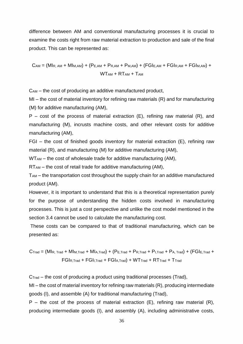
36
difference between AM and conventional manufacturing processes it is crucial to
examine the costs right from raw material extraction to production and sale of the final
product. This can be represented as:
CAM = (MIR, AM + MIM,AM) + (PE,AM + PR,AM + PM,AM) + (FGIE,AM + FGIR,AM + FGIM,AM) +
WTAM + RTAM + TAM
CAM – the cost of producing an additive manufactured product,
MI – the cost of material inventory for refining raw materials (R) and for manufacturing
(M) for additive manufacturing (AM),
P – cost of the process of material extraction (E), refining raw material (R), and
manufacturing (M), incrusts machine costs, and other relevant costs for additive
manufacturing (AM),
FGI – the cost of finished goods inventory for material extraction (E), refining raw
material (R), and manufacturing (M) for additive manufacturing (AM),
WTAM – the cost of wholesale trade for additive manufacturing (AM),
RTAM – the cost of retail trade for additive manufacturing (AM),
TAM – the transportation cost throughout the supply chain for an additive manufactured
product (AM).
However, it is important to understand that this is a theoretical representation purely
for the purpose of understanding the hidden costs involved in manufacturing
processes. This is just a cost perspective and unlike the cost model mentioned in the
section 3.4 cannot be used to calculate the manufacturing cost.
These costs can be compared to that of traditional manufacturing, which can be
presented as:
CTrad = (MIR, Trad + MIM,Trad + MIA,Trad) + (PE,Trad + PR,Trad + PI,Trad + PA, Trad) + (FGIE,Trad +
FGIR,Trad + FGII,Trad + FGIA,Trad) + WTTrad + RTTrad + TTrad
CTrad – the cost of producing a product using traditional processes (Trad),
MI – the cost of material inventory for refining raw materials (R), producing intermediate
goods (I), and assemble (A) for traditional manufacturing (Trad),
P – the cost of the process of material extraction (E), refining raw material (R),
producing intermediate goods (I), and assembly (A), including administrative costs,

37
machine costs, and other relevant costs for traditional manufacturing,
FGI – the cost of finished goods inventory for material extraction (E), refining raw
material (R), and producing intermediate goods (I), and assemble (A) for traditional
manufacturing (Trad),
WTTrad – the cost of wholesale trade for traditional manufacturing (Trad),
RTTrad – the cost of retail trade for traditional manufacturing (Trad),
TTrad – the transportation cost throughout the supply chain for a product made using
traditional manufacturing (Trad). (Thomas, 2015)
It is also vital to understand that AM might have significant cost saving benefits when
examined in an assembled product. This is because traditional manufacturing often
involves various intermediate products which are transported and assembled unlike
AM which can create an assembly in a single build. Good analogy would be an engine
which when traditionally made has parts manufactured and shipped for assembly from
different locations with each location having its own manufacturing side, inventory,
personal, logistics infrastructure etc. AM has a possibility of producing the entire engine
in one build. It can further aid in making an engine with lesser material, more efficient
operation and a longer life, due to its flexibility in design when compared to traditional
manufacturing. It might not be possible to capture many of these benefits using
previously mentioned costs model. It is important to use cradle-to-grave analysis to
understand and quantify these benefits. Breaking down the costs involved in supply
chain can help better understand effects of AM. Unfortunately, collection and
assessment of these costs for the specific part can be difficult and expensive, but these
are the costs that AM may impact.
4.2.2 Resource consumption perspective
Land, labor and time make up a major portion of the cost elements for production.
These three elements can be considered as the main resources used for production.
Companies often try to reduce the use of these resources in making a product. It is
vital understand the effects of AM adoption on the usage of these resources. Possible
outcomes of AM can be an ideal reduction in the resources used for manufacturing or
might result in trade-off between the resources. Furthermore, manufactured products
consume resources when being used. Also, disposal of the product will also lead to

38
resource utilization. Thus, the total advantage of AM can be understood by exploring
the difference in use of resources (land, labor and time) during the production,
utilization and disposal along with the utility of the product compared with that of
traditional manufacturing techniques. This can be better explained by equation below.
(Thomas, 2015)
TAL = (LAM,P + LAM,U + LAM,D) – (LT,P + LT,U + LT,D)
TALB = (LBAM,P + LBAM,U + LBAM,D) – (LBT,P + LBT,U + LBT,D )
TAT = (TAM,P + TAM,U + TAM,D) – (TT,P + TT,U + TT,D)
TAU = U(PAM) – U(PT)
TA – the total advantage of additive manufacturing compared to traditional methods
for land (L), labor (LB), time (T), and utility of the product (U)
L - the land or natural resources needed using additive manufacturing processes (AM)
or traditional methods (T) for production (P), utilization (U), and disposal (D) of the
product
LB - the labor hours per hour needed using additive manufacturing processes (AM) or
traditional methods (T) for production (P), utilization (U), and disposal (D) of the product
T - the time needed using additive manufacturing processes (AM) or traditional
methods (T) for production (P), utilization (U), and disposal (D) of the product
U(PAM) - the utility of a product manufactured using additive manufacturing processes,
including the utility gained from increased abilities, enhancements, and useful life.
U(PT)- the utility of a product manufactured using traditional processes, including the
utility gained from increased abilities, enhancements, and useful life.
Though, it is not easy to measure all these factors. It is vital to consider them while
trying to understand the advantages of adopting AM. A classic example to better
understand this is the production of steering/suspension component used in
automobiles. A typical supply chain flow of a steering/suspension component can be
seen in figure 14. Adoption of AM in this case can lead to various advantages, in terms

39
of monitory and resource values. Also, it might be difficult and expensive track and
compare these costs through the entire supply chain. It is vital to understand that an
exhaustive understanding of these components is necessary while examining the issue
(Thomas, 2015).
Figure 14 Material supply chain for motor vehicle steering and suspension
component (Thomas, 2015)
Unlike traditional tooled manufacturing processes which is limited to huge centralized
manufacturing sites, the adoption of AM can reduce the significance of such
economies of scale and help to decentralized the manufacturing to points of
consumption. (D’Aveni, 2013)
Adoption of AM can have specific benefits on the supply- side or demand- side of an
organization depending on the type of supply chain chosen. Organisation can opt to
adopt either centralised or decentralized supply chain when adopting AM. Centralised
supply chain has more effects on the upstream or supply- side of the supply chain and
decentralized supply chain has more effects on downstream or demand- side of the
Raw materials Material refining Intermediate parts Finished product

40
supply chain. Centralised supply chain can be favourable when logistic costs are low
and decentralised when logistic costs are high. In the centralized supply chain adoption
of AM helps organisations to reach higher level of vertical integration while
decentralized supply chain helps to achieve close proximity to customers. (Oettmeier
and Hofmann, 2016) It is important for organisations to understand the benefits and
challenges of adoption centralised or decentralized supply chain. Figures 15, 16 and
17 show the schematic of different types of supply chain.
Figure 15 Supply chain in traditional manufacturing (Oettmeier and Hofmann, 2016)
Figure 16 Centralised supply chain in additive manufacturing (Oettmeier and
Hofmann, 2016)

41
Figure 17 Decentralised supply chain in additive manufacturing (Oettmeier and
Hofmann, 2016)
In the supply chain of the traditional manufacturing, organization procures raw
materials and parts from numerous suppliers to produce a product. In this case
customizing the products with the respect to changes in customer needs can prove to
be time consuming and expensive. This is mainly due to the involvement of various
suppliers and tooling costs. In the case of centralized supply chain in AM, the
organization procures raw materials or small parts from fewer suppliers. AM’s ability to
manufacture parts with inbuilt functionality helps to reduce sub-assembly activities and
simplify manufacturing steps. This in turn helps to lower transportation. In
decentralized supply chain in AM, production is moved closer to customers. AM helps
to improve customization of products with changing customer needs without increased
lead times. (Oettmeier and Hofmann, 2016)
4.2.3 Lead Time Benefits
Reduction of lead time can have various benefits to the organisation. Reduction in lead
time can increase company’s ability to predict and respond to changes in market
demands. The three competitive dimensions, price, product differentiation and delivery
time are dependent on lead time. Thus, the reduction of lead time can help to reach
the satisfactory level of these dimensions. On the supply side, lead time is directly
proportional to the size of the inventory and safety stock levels. The safety stock levels
are required to prevent stock outs. High levels of safety stock results in tied-up capital,
part obsolescence, damaged goods and warehouse operations. Thus, a reduction in

42
lead time can help to prevent this. Long lead time can result in over or under production
and inaccurate inventory levels. This is due to the fact that long lead time magnifies a
bullwhip effect. Furthermore, reduction in lead time makes it easier to plan operational
activities and helps improve cash flow by reducing the tie up of capital in physical
resources. (Magnusson and Simonsson, 2012)
4.3 ECONOMIES OF SCALE
“Economies of scale is the cost advantage that arises with increased output of a
product” (investopedia.com, 2017).
Economies of scale forms a central feature when it comes to traditional mass
manufacturing approaches. However, AM technologies do not exhibit this feature. This
portrays AM as a technology that can operate without having to increase its output in
order to decrease its manufacturing costs. (Pine, 1993)
A significant portion of the cost structure of conventional manufacturing processes is
made up of tooling expenses, which is amortized over the production runs (Ruffo et al.,
2007, Atzeni et al., 2012).
Due to the fact that AM processes do not require tooling cutting implements, moulds
or dies, economies of scale do not exist for the process. However, it is expected that
future improvements in AM technology might give rise to economies of scale. One such
improvement would be an increase of available build volume, which will result in
lowering of the average costs as some of the fixed process steps such as warm-up or
cool-down can be amortized over the larger build volume. (Baumers et al., 2014)
Furthermore, developments in AM processes aim to improve productivity by making
the build process more continuous or even have multiple depositions. Thus, it is vital
to understand that economies of scale in AM is possible with increased throughput or
physical scaling-up. Hence, it is hasty to assume that AM processes have the
disadvantages when it comes to high volume production. Moreover, adoption of AM
leads to significant reduction of front-end fixed costs related to introductions of new
products which in turn helps to promote product innovation.
Furthermore, future companies will require to choose the adoption of AM by

43
considering the type of product that it wishes to produce. For parts that are produced
in large volumes, companies can take advantage of economies of scale offered by
traditional manufacturing processes. But in case of parts that are produced low
volumes, highly customized and have complex features, companies can take
advantage of economies of one offered by AM techniques. (Petrick and Simpson 2013)
4.4 CHALLENGES AND RISKS
Although, AM has numerous advantages which organisations can benefit from, it is
vital to understand these benefits come with associated challenges or risks. Some of
the major challenges of adopting AM are:
1. Lack of material variety.
2. Intellectual property issues.
3. Shortfall of skilled designers and engineers in AM.
4. Need for post processing of AM parts.
5. Further developments needed in standards and regulations for AM process
and parts.
6. While making supply chains more agile and reducing logistic costs, adoption
of AM runs the risk of increased manufacturing costs and the absence of
economies of scale.
7. Though supply chain complexity decreases, adoption of AM will require
complex testing and quality assurance processes, which in turn leads to
complexity in downstream supply chain.
8. In cases of advanced applications, AM processes still need improvements in
terms of quality and accuracy.
9. Uncertainty in future technical developments of AM creates a financial risk of
investment (Mohr and Khan, 2015).
10. It is also important to remember that similar to traditional manufacturing
processes, parts manufactured through AM are also prone to defects. (Ford,
Despeisse, 2016)

44
4.5 BUSINESS MODEL
In general, business model describes the company’s logic of creating and capturing
value. On a more detailed level. Business model refers to “a system of interdependent
activities within and across organizational boundaries that enable the organization and
its partners to create value and capture part of that value”. (Zott and Amit, 2010)
Unlike some new technologies which can be implemented with the same existing
business models, AM technologies being disruptive need reshaping or reinvention of
the current business model to be able to capture its value (Chesbrough, 2010).
AM business models should be seen as complementary and possibly coexist with
traditional business models rather than a replacement for them. In areas of repair,
refurbishment and remanufacturing, AM opens up new business opportunities.
Adoption of AM can help extending product life cycles and provide various options to
close the loop. This makes it attractive for organisations to adopt product-service
business models. Many organisations such as Caterpillar, GE, Siemens have been
able to adopt such business models with the help of AM technologies.

45
5 DISCUSSION AND CONCLUSIONS
The department deals with customized products. This means the production volume is
low and the product design is highly variable. Producing these parts through the
conventional manufacturing methods have high lead times for low quantities. Due to
this, the company is looking for other manufacturing techniques which can help in
reducing the lead times.
This study considers AM as one technology to help in reducing the lead times. From
the cost and lead time calculations, it can be concluded that AM can greatly reduce the
lead time taken to manufacture a part. However, the production costs involved in AM
are considered to be higher than those of conventional manufacturing processes. This
cost difference can be justified by the huge reduction in the lead times. Scania can
take advantage of this lead time reduction by adopting AM.
5.1 FUTURE OF AM IN SCANIA
It is often complicated for companies to choose how to deploy AM across their
businesses. Deloitte has come up with four strategic paths that companies can take
when adopting AM in their products and/or supply chain. The framework for
understanding these paths and their value is shown in figure 18 - Framework for AM
paths and value.
Path I: This is for companies which seek to use AM to improve the value delivery for
their products within the already existing supply chain. These companies do not pursue
profound changes in their supply chain or products.
Path II: This is for companies which seek supply chain transformation through the
adoption of AM. Adopting this path helps companies with supply chain evolution by
increasing the responsiveness and flexibility, reduction in required inventory, supply
chain decentralization to mention a few.
Path III: This is for companies which seek to achieve better performance or innovation
in their products. Adopting this path helps in product customization, increased product
functionality, better market responsiveness etc.
Path IV: This is for companies which seek to transform both their supply chain as well
as their products in pursuit of a completely new business model. (deloitte.com, 2017)

46
Figure 18 Framework for AM paths and value (DUPress.com, 2017)
It would be crucial for Scania to take into the consideration the above-mentioned steps
before adoption AM. Each of the paths come with its own benefits and limitations.
Scania can adopt a path based on its needs. Furthermore, for the purpose of cost
calculations Scania should select parts which have the potential to take advantage of
AM capabilities. Few such characteristics are parts which need customization, parts
with increased functionality through design optimization and parts of low volume. DfAM
techniques can be used to make such parts more suitable for AM. It would be beneficial
for Scania to include AM skill developments in its organization. This will make it easier
for future AM adoption in Scania.
5.2 FUTURE OF AM IN MANUFACTURING
AM system costs have decreased by 42 % between 2001 and 2013 (Wohlers, 2014).
However, it is vital to understand that even if the average production costs can be
reduced by reduction in the system purchase price rather than the increment of system
productivity, the overheads emerging from running unproductive systems may result

47
in high total expenditure. To overcome this, it is important that the deposition rate of
AM systems should be improved closer to those of conventional manufacturing
processes. The costs of AM systems might not be of primary importance, as long as
the systems deposition rates are high enough to amortise the machine costs.
(Baumers et al., 2016) Furthermore, increasing the dimensions of the available build
volume can lead to a lower part costs. This is due to the fact that certain fixed process
elements such as warm up and cool down can be amortised over the larger build
volume. (Baumers et al., 2014) Thus, future improvements in deposition rate and build
volume size will have the greatest effect on reducing part costs. This also shows that
economies of scale can be achieved in AM processes by increasing machine
throughput.
Although developments in materials can help in the wide spread use of AM, other
aspects of AM which are the subject of research on the global scale are,
• Process speed;
• Dimensional accuracy;
• Surface finish;
• Repeatability.
Although improvements in these aspects have come a long way from AM being rapid
prototyping technology, further improvements can help make AM equally attractive as
conventional manufacturing processes. Furthermore, many manufacturers are able to
cope with current system limitations to their advantage. (Ruffo et al., 2006)
Adoption of AM can bring a future where: “The factories of the future will be more
varied, and more distributed than those of today […] The production landscape will
include capital intensive super factories producing complex products; reconfigurable
units integrated with the fluid requirements of their supply chain partners; and local,
mobile and domestic production sites for some products. Urban sites will become
common as factories reduce their environmental impacts. The factory of the future may
be at the bedside, in the home, in the field, in the office and on the battlefield” (BIS,
2013). Furthermore, the supply chain networks become one where “logistics may be
more about delivering digital design files – from one continent to printer farms in
another – than about containers, ships and cargo planes” (PWC, 2014).

48
Adoption of AM can have a huge influence on the company’s capabilities. Despite the
higher unit costs compared to traditional manufacturing methods, the company attains
higher flexibility through AM adoption. Thus, AM is more suitable for firms which seek
a high flexibility position. However, it is vital to remember that AM can also reduce
costs for certain products that have complex designs which can be expensive to
manufacture using traditional processes. Moreover, reduction of material and system
costs in the future can make AM attractive to more companies. (Thomas, 2015)

49
6 REFERENCES
Atzeni, E., Salmi, A. (2012) ‘Economics of additive manufacturing for end-usable metal
parts’. International Journal of Advanced Manufacturing Technology, 62, pp. 1147-
1155. doi:10.1007/s00170-011-3878-1
Baumers, M., Dickens, P., Tuck, C., Hague, R. (2016) ‘The cost of additive
manufacturing: machine productivity, economies of scale and technology-push’, 102,
pp.193-201. doi: 10.1016/j.techfore.2015.02.015
Baumers, M., Tuck, C., Dickens, P., Hague, R. (2014). ‘How can material jetting
systems be upgraded for more efficient multi-material additive manufacturing’.
Proceedings of the Solid Freeform Fabrication (SFF) Symposium.
BIS (2013) Future of Manufacturing: a New Era of Opportunity and Challenge for the UK – Summary Report.
Bogers, M., Hadar, R., Bilberg, A. (2016) ‘Additive manufacturing for consumer-centric
business models: Implications for supply chains in consumer goods manufacturing’,
102, pp. 225-239. doi: 10.1016/j.techfore.2015.07.024
Chen, D., Heyer, S., Ibbotson, S., Salonitis, K., Steingrímsson, J.G., Thiede, S. (2015). ‘Direct digital manufacturing: definition, evolution, and sustainability implications’. Journal of Cleaner Production, 107, pp.615-625. doi: 10.1016/j.jclepro.2015.05.009
Chesbrough, H. (2010). ‘Business Model Innovation: Opportunities and Barriers’. Long
Range Planning, 43(2-3), pp. 354-363. doi: 10.1016/j.lrp.2009.07.010
F42 Committee (2012) Standard Terminology for Additive Manufacturing
Technologies. West Conshohocken, PA: ASTM International.
Fachini, L., Magalani, A., Robotti, P., Molinari, A. (2009). ‘Microstructure and
mechanical properties of Ti-6Al-4 V produced by electron beam melting of pre-alloyed
powders’. Rapid Prototyping Journal, 15 (3), pp. 171–178. doi:
10.1108/13552540910960262

50
Ford, S., Despeisse, M. (2016) ‘Additive manufacturing and sustainability: an
exploratory study of the advantages and challenges’, Journal of Cleaner Production,
137, pp. 1573-1587. doi: 10.1016/j.jclepro.2016.04.150
Gibson, I., Rosen, D.W., Stucker, B. (2010). Additive Manufacturing Technologies,
New York: Springer, pp. 1-2. doi: 10.1007/978-1-4419-1120-9_1
Gibson, L.J. and Ashby, M.F. (1997). Cellular solids: structure and properties.,
Cambridge,UK: Cambridge University Press.
Gokuldoss, P.K., Kolla, S., Eckert, J. (2017) ‘Additive Manufacturing Processes:
Selective Laser Melting, Electron Beam Melting and Binder Jetting—Selection
Guidelines’, 10(6), pp. 672. doi: 10.3390/ma10060672
Gong, X., Anderson, T., Chou, K. (2014). ‘Review on powder-based electron beam
additive manufacturing technology’. Manufacturing review, 1, pp. 1-12. doi:
10.1051/mfreview/2014001.
Guo, N., Leu, M. (2013). ‘Additive manufacturing: technology, applications and
research needs’. Frontiers of Mechanical Engineering, 8(3), pp.215-243. doi:
10.1007/s11465-013-0248-8
Herzog, D., Seydab, V., Wyciskb, E., Emmelmannab, C. (2016). ‘Additive manufacturing of metals’. Acta Materialia, 117, pp. 371-392. doi: 10.1016/j.actamat.2016.07.019
http://additivemanufacturing.com/2016/11/01/xjet-to-present-worlds-first-direct-3d-
metal-ink-jet-system-using-nanoparticle-jetting-technology/
http://www.arcam.com/technology/electron-beam-melting/hardware (Accessed: 20
September 2017).
http://www.arcam.com/technology/products/arcam-q20 (Accessed: 20 September
2017).
http://www.insidemetaladditivemanufacturing.com/blog/benefits-of-laser-based-
powder-bed-fusion-technology (Accessed: 19 September 2017).
http://www.lboro.ac.uk/research/amrg/about/the7categoriesofadditivemanufacturing/

51
(Accessed: 14 September 2017).
https://dupress.deloitte.com/dup-us-en/focus/3d-opportunity/additive-manufacturing-
3d-printing-supply-chain-transformation.html (Accessed: 20 September 2017).
https://www.3dhubs.com/knowledge-base/additive-manufacturing-technologies-
overview (Accessed: 14 September 2017).
https://www.engineersgarage.com/articles/3d-printing-processes-directed-energy-
deposition (Accessed: 19 September 2017).
https://www.investopedia.com/terms/e/economiesofscale.asp (Accessed: 20
September 2017).
Krar, S., Gill, A. (2003). Exploring advanced manufacturing technologies, New York:
Industrial Press, pp.726-727.
Krishnan, M., Atzeni, E., Canali, R., Manfredi, D., Calignano, F., Ambrosio, E., Iuliano,
L. (2013). Influence of post-processing operation on mechanical properties of
AlSi10Mg parts by DMLS. In:The International Conference On Advanced Research in
Virtual And Rapid Prototyping, Leiria, Portugal: CRC Press, London, pp. 243–248.
Magnusson, D., Simonsson, P. (2012). ‘A framework for decreasing lead times by
supplier collabration’. Department of Technology Management and Economics.
Chalmers University of Technology, pp. 2-3.
Mohr, S., Khan, O. (2015). ‘3D Printing and Supply Chains of the Future’. Innovations and Strategies for Logistics and Supply Chains, pp. 148 – 174.
Murr, L.E., Gaytan, S.M., Medina, F., Martinez, E., Martinez, J.L., Hernandez, D.H., Machado, B.I., Ramirez, D.A., Wicker, R.B. (2010). ‘Characterization of Ti–6Al–4V open cellular foams fabricated by additive manufacturing using electron beam melting’. Materials Science & Engineering A, 527(7), pp.1861-1868. doi: 10.1016/j.msea.2009.11.015
Murr, L.E., Gaytan, S.M., Ramirez, D.A., Martinez, E., Hernandez, J., Amato, K.N.,
Shindo, P.W., Medina, F.R., Wicker, R.B. (2012) ‘’Metal fabrication by additive
manufacturing using laser and electron beam melting technologies’, Journal of material
science technology, 28 (1) (2012), pp. 1-14.

52
Oetmeier, K. and Hofmann, E. (2016). ‘Additive manufacturing technology adoption:
an empirical analysis of general and supply chain-related determinants’. Journal of
Business Economics, 87(1), pp. 97-124.
Petrick, I.J. and Simpson, T.W. (2013). ‘3D Printing Disrupts Manufacturing: How
Economies of One Create New Rules of Competition’. Research-Technology
Management. 55(6), pp. 12-16. doi: 10.5437/08956308X5606193.
Petrovic, V., Vicente Haro Gonzalez, J., Jordá Ferrando, O., Delgado Gordillo, J., Ramon Blasco Puchades, J., Portoles Grinan, L. (2011). ‘Additive layered manufacturing: Sectors of industrial application shown through case studies’. International Journal of Production Research, 49(4), pp.1061-1079. doi: 10.1080/00207540903479786
Piller, F., Weller, C., Kleer, R. (2015) Business models with additive manufacturing:
opportunities and challenges from the perspective of economics and management.
New York: Springer, pp. 39–48.
Pine, B.J. (1992). Mass Customization: The New Frontier in Business Competition,
Boston:Harvard Business Review Press.
Ponfoort, O., Ambrosius, W., Barten, L., Duivenvoorde, G., van den Hurk, L., Sabirovic,
A., Teunissen, E. (2014) Successful Business Models for 3D Printing: Seizing
Opportunities with a Game Changing Technology. Utrecht: Berenschot.
PWC (2014) 3D Printing and the New Shape of Industrial Manufacturing available at: http://www.pwc.com/us/en/industrial-products/assets/3d-printing next_manufacturing-pwc.pdf (accessed 12.10.17.)
Rose, D.W. (2014). ‘Research supporting principles for design for additive
manufacturing’. Virtual and Physical Prototyping, 9(4), pp. 225-232. doi:
10.1080/17452759.2014.951530
Ruffo, M., Hague, R. (2007). ‘Cost estimation for rapid manufacturing – simultaneous
production of mixed components using laser sintering’. Journal of Engineering
Manufacture, 221(11), pp. 1585-1591. doi:10.1243/09544054JEM894.
Ruffo, M., Tuck, C., Hague, R. (2006). ‘Cost estimation for rapid manufacturing – laser
sintering production for low to medium volumes’. Journal of Engineering Manufacture,
220(9), pp. 1417-1427. doi: 10.1243/09544054JEM517

53
Stucker, B. (2012). Additive manufacturing technologies: technology introduction and
business implications, Washington, DC:The National Academies Press, pp.5-14.
Thomas, D. (2015) ‘Costs, benefits, and adoption of additive manufacturing: a supply
chain perspective’, The International Journal of Advanced Manufacturing Technology,
85(5-8), pp. 1857 – 1876. doi: 10.1007/s00170-015-7973-6
Weller, C., Kleer, R., Piller, F.T. (2015). ‘Economic implications of 3D printing: Market
structure models in light of additive manufacturing revisited’, International Journal of
Production Economics, 164, pp. 43-56. doi: 10.1016/j.ijpe.2015.02.020
Wohlers, T. (2013) ‘Additive manufacturing and 3D printing state of the industry’
Annual Worldwide Progress Report, Wohlers Associates.
Wohlers, T. (2014). ‘Wohlers Report 2014: Additive Manufacturing and 3D Printing
State of the Industry’. Wohlers Assocoates, Inc.,
Zott, C., Amit, R. (2010). ‘Business model design: An activity System Perspective’.
Long Range Planning, 43(2-3), pp. 216-226. doi: 10.1016/j.lrp.2009.07.004

54
7 Appendix 1
Appendix 1 – Cost calculation
Co
nsu
ma
ble
s
Bu
ild
Tim
e
Pre
pa
rati
on
,
pre
he
ati
ng
an
d c
oo
lin
g
To
tal
Pa
rt
Vo
lum
eM
ate
ria
lM
ate
ria
l
De
nsi
ty
Pa
rt
We
igh
t
Bu
ild
Po
wd
er
(Ti6
Al4
V)
un
it c
ost
Bu
ild
Po
wd
er
(Ti6
Al4
V)
co
st
Wa
sta
ge
co
st
(10%
)
To
tal
La
bo
ur
Un
it C
ost
La
bo
ur
Ho
urs
La
bo
ur
Co
st
En
erg
y
Un
it C
ost
En
erg
y
Ho
urs
Ma
ch
ine
Po
we
r
Use
En
erg
y
Co
st
De
pre
cia
tio
n
pe
r h
ou
r
Ho
urs
Ma
ch
ine
use
d
De
pre
cia
tio
n
Co
st
Co
nsu
ma
ble
s
Co
st (
Ba
se
Pla
te +
He
at
Sh
ield
)
hrs
hrs
hrs
cm
3-
g/c
m3
kg
sek/k
gsek
sek
sek
sek/h
our
hrs
sek
sek/k
Whrs
kW
/hr
sek
sek/h
rhr
sek
sek
sek
28
432
387,0
8Ti6
Al4
V4,4
21,7
11
1400
2395
239,5
2635
250
41000
0,6
32
7134
127,2
632
4072
298
8139
29
433
403,4
Ti6
Al4
V4,4
21,7
83
1400
2496
249,6
2746
250
41000
0,6
33
7139
127,2
633
4200
298
8383
37,5
441,5
100,7
2Ti6
Al4
V4,4
20,4
45
1400
623
62,3
685
250
41000
0,6
41,5
7174
127,2
641,5
5281
298
7438
To
tal
Co
st
Part
1
Part
2
Part
3
Pa
rt N
um
be
r
Bu
ild
Tim
e (
hrs
)B
uil
d P
ow
er
(Ti6
Al4
V)
co
stL
ab
ou
r C
ost
En
erg
y C
ost
De
pre
cia
tio
n C
ost

55
8 Appendix 2
Appendix 2 – Lead time calculation
Build Time (hrs)Post Processing
(hrs)
Quality control
(hrs)
Internal
Logistics (hrs)
Total Lead Time
(Days)
32 1 1 4 2
33 1 1 4 2
41,5 1 1 4 3
Part Number
Total Lead Time (Days)
Part 1
Part 2
Part 3