addendum to edmonds community development code chapter …
TRANSCRIPT

ADDENDUM TO EDMONDS COMMUNITY DEVELOPMENT CODE CHAPTER 18.30
(EDMONDS STORMWATER ADDENDUM)
June 8, 2017

Note: Some pages in this document have been purposely skipped or blank pages inserted so that this document will copy correctly when duplexed.
JUNE 2017 EDMONDS STORMWATER ADDENDUM
15-05994-000_stormwateraddendum.docx TABLE OF CONTENTS i
CONTENTS 1 Introduction ...............................................................................................................................1
2 How to Use this Addendum ......................................................................................................3
2.1 SWMMWW Volume I ......................................................................................................3 2.2 SWMMWW Volume II .....................................................................................................4 2.3 SWMMWW Volume III ....................................................................................................4 2.4 SWMMWW Volume IV ...................................................................................................4 2.5 SWMMWW Volume V .....................................................................................................4 2.6 Addendum Content Not Covered in the SWMMWW ......................................................5
3 Applicability of the Minimum Requirements ...........................................................................7
3.1 Thresholds and Applicability ............................................................................................9 3.1.1 Additional Requirements for Road-Related Projects .........................................9 3.1.2 New Connections to the City’s MS4 ..................................................................9 3.1.3 Comparisons to the SWMMWW .....................................................................10
4 Project Basin Location and Applicable Requirements ...........................................................11
4.1 Determining Downstream Receiving System(s) .............................................................11 4.2 Other Considerations .......................................................................................................11
5 Project Minimum Requirements .............................................................................................13
5.1 Minimum Requirement No. 1 – Preparation of Stormwater Site Plans ..........................13 5.2 Minimum Requirement No. 2 – Construction Stormwater Pollution Prevention
Plan ................................................................................................................................13 5.3 Minimum Requirement No. 3 – Source Control of Pollution .........................................13 5.4 Minimum Requirement No. 4 – Preservation of Natural Drainage Systems and
Outfalls ............................................................................................................................14 5.5 Minimum Requirement No. 5 – On-Site Stormwater Management ................................15 5.6 Minimum Requirement No. 6 – Runoff Treatment .........................................................17
5.6.1 Edmonds-Specific Oil and Floatables Control .................................................17 5.7 Minimum Requirement No. 7 – Flow Control ................................................................17 5.8 Minimum Requirement No. 8 – Wetland Protection .......................................................18 5.9 Minimum Requirement No. 9 – Operation and Maintenance .........................................18
6 Additional Requirements ........................................................................................................19
6.1 Protection of LID Facilities During Construction ...........................................................19 6.1.1 General Erosion and Sediment Control BMPs Applicable to LID ...................19 6.1.2 Additional Construction Techniques for LID BMPs ........................................20 6.1.3 BMP-Specific Construction Techniques ..........................................................23

EDMONDS STORMWATER ADDENDUM JUNE 2017
ii TABLE OF CONTENTS pjj 15-05994-000_stormwateraddendum.docx
6.2 Off-Site Analyses and Documentation ............................................................................25 6.2.1 Category 1 Projects ...........................................................................................26 6.2.2 Category 2 Projects ...........................................................................................26
6.3 Design Requirements for Detention Vaults and Pipes ....................................................28 6.3.1 Sizing ................................................................................................................28 6.3.2 Design Criteria ..................................................................................................29
6.4 Underground Injection Controls ......................................................................................29
7 Submittal Requirements ..........................................................................................................31
7.1 Category 1 Stormwater Site Plans ...................................................................................31 7.2 Category 2 Stormwater Site Plans ...................................................................................31
APPENDICES Appendix A – On-Site Stormwater Management BMP Infeasibility Criteria Appendix B – Methods for Determining Design Infiltration Rates Appendix C – Checklists for Various Project Submittal, Review, and Field Procedure Elements Appendix D – Design Checklists for the Main On-Site Stormwater Management BMPs
LIST OF FIGURES Figure 3.1. Flow Chart for Determining Requirements for Development. ................................8
Figure 7.1. Typical Category 1 Stormwater Site Plan Components. .......................................31
Figure 7.2. Typical Category 2 Stormwater Site Plan Components. .......................................32
JUNE 2017 EDMONDS STORMWATER ADDENDUM
1. INTRODUCTION 1
1 INTRODUCTION This Edmonds Stormwater Addendum (Addendum) provides direction for implementing the City of Edmonds Community Development Code (ECDC) Chapter 18.30, Stormwater Management. The City of Edmonds is required to regulate stormwater discharges to the municipal stormwater system and to waters of the state, in compliance with the Western Washington Phase II National Pollutant Discharge Elimination System (NPDES) Municipal Stormwater Permit (the Permit). Under the Permit, the City must establish and apply the minimum requirements specified in the Permit and provide design guidance for stormwater quality and quantity control for development projects in Edmonds. Through ECDC Chapter 18.30 and this Addendum, the City is complying with federal requirements under the Clean Water Act and the Permit.
This Addendum is organized into 7 chapters, briefly summarized below:
• Chapter 2 – How to Use this Addendum includes information on how to use the Addendum in conjunction with the ECDC and Ecology’s 2014 Stormwater Management Manual for Western Washington (SWMMWW), and to clarify for users where the ECDC, SWMMWW, or Addendum apply.
• Chapter 3 – Applicability of the Minimum Requirements includes details on the thresholds that determine the applicability of the minimum requirements to different projects. This information is based on SWMMWW Volume I, Section 2.4, but has been updated to reflect the specific requirements of ECDC 18.30. Chapter 3 also includes a brief summary of how ECDC 18.30.060 compares to the SWMMWW (regarding applicability of the minimum requirements).
• Chapter 4 – Project Basin Locations and Applicable Requirements describes downstream receiving waterbodies and/or drainage systems in the city, which will affect how the minimum requirements apply to a given project (primarily Minimum Requirements No. 5, No. 6, and No. 7). Chapter 4 also includes a brief discussion of the unique soil and topographical conditions in the City of Edmonds.
• Chapter 5 – Project Minimum Requirements highlights the primary differences between the minimum requirements presented in the SWMMWW and those in the ECDC, and provides additional details and guidance to help projects comply with each minimum requirement.
• Chapter 6 – Additional Requirements includes additional information on City-specific requirements that are not fully described in the SWMMWW or ECDC. Specific topics include:
1. Additional requirements pertaining to Construction Stormwater Pollution Prevention Plans (SWPPPs) Element No. 13 – Protect Low Impact Development (LID) Best Management Practices (BMPs)
2. Details on the off-site analyses and documentation required to comply with Minimum Requirement No. 4, Preservation of Natural Drainage Systems and Outfalls
EDMONDS STORMWATER ADDENDUM JUNE 2017
2 1. INTRODUCTION
3. Design requirements for detention vaults and pipes when used to meet Minimum Requirement No. 5
4. Information on Underground Injection Controls (UICs)
• Chapter 7 – Submittal Requirements summarizes the process and requirements for preparing project submittals that meet the requirements of the SWMMWW, the ECDC, and this Addendum.
The appendices included in this Addendum provide additional background information and requirements related to stormwater management in the city. (Also note that there are several additional pertinent appendices within the SWMMWW that are adopted by reference.) The following City-specific appendices are included in this Addendum:
• Appendix A – On-Site Stormwater Management BMP Infeasibility Criteria
• Appendix B – Methods for Determining BMP Design Infiltration Rates
• Appendix C – Checklists for Various Project Submittal, Review, and Field Procedure Elements
o Checklist 1 – Category 1 Stormwater Site Plans
o Checklist 2 – Category 2 Stormwater Site Plans
o Checklist 3 – Construction SWPPP Drawings and Report
o Checklist 4 – Methods for Determining Infiltration Rates
o Checklist 5 – Field and Design Procedures for Bioretention, Permeable Pavement, Rain Gardens, and Downspout Infiltration Systems
o Checklist 6 – Procedures for Infiltration Trenches and Basins
• Appendix D – Design Checklists for the Main On-Site Stormwater Management BMPs
o Checklist 7 – Post-Construction Soil Quality and Depth
o Checklist 8 – Sheet Flow Dispersion
o Checklist 9 – Concentrated Flow Dispersion
o Checklist 10 – Bioretention Cells, Swales, and Planter Boxes
o Checklist 11 – Permeable Paving
o Checklist 12 – Rain Gardens
o Checklist 13 – Downspout Infiltration
o Checklist 14 – Downspout Dispersion
o Checklist 15 – Perforated Stub-out Connections
JUNE 2017 EDMONDS STORMWATER ADDENDUM
2. HOW TO USE THIS ADDENDUM 3
2 HOW TO USE THIS ADDENDUM Review ECDC Chapter 18.30.030 and 18.30.040 to determine if the City’s Stormwater Code and this Addendum apply to your project. Review the definitions section of ECDC Chapter 18.30.10 (and if necessary the Glossary in SWMMWW Volume I, Appendix G) for clarification on terminology used in ECDC Chapter 18.30 and this Addendum.
As per ECDC Chapter 18.30.60, the stormwater management requirements in the City of Edmonds – including but not limited to thresholds, definitions, minimum requirements, adjustment and variance criteria, and exceptions to these requirements – shall be governed by the 2014 SWMMWW, with additional requirements and modifications as outlined in the provisions of ECDC Chapter 18.30 and this Addendum. Project proponents must review ECDC 18.30 (18.30.060 in particular) and this Addendum to identify how the City’s requirements and the requirements of the SWMMWW apply to a given project. In the event of inconsistencies between the various provisions, the more stringent provisions shall apply, unless otherwise approved by the City. Where requirements in this Addendum are also covered in any other law, ordinance, resolution, rule, or regulation of any kind (i.e., outside of ECDC Chapter 18.30), the more restrictive requirement shall govern, unless otherwise approved by the City.
This Addendum includes information to supplement or elaborate on the guidelines and requirements outlined in ECDC Chapter 18.30 and the SWMMWW. To highlight for Addendum users where the ECDC, SWMMWW, or Addendum apply, the following sections outline the general applicability of each document, summarized according to the organization of the SWMMWW. Note however that the SWMMWW is not always written in a manner that is suitable as a municipal regulatory tool, therefore there are known overlaps among the ECDC, SWMMWW, and Addendum. As such, this section is only intended to be a guide, not a definitive resource on SWMMWW applicability. When questions or potential inconsistencies arise, project proponents should contact the City for clarification and interpretation.
2.1 SWMMWW VOLUME I • Chapter 1 – Introduction (refer to the SWMMWW)
• Chapter 2 – Minimum Requirements for New Development and Redevelopment. Users should refer first to ECDC Chapter 18.30.60 and this Addendum. Note that some portions of ECDC 18.30.60 refer back to the SWMMWW as well as specific sections of this Addendum. In addition, note that for all minimum requirements that require flow modeling, unless otherwise specified, all continuous modeling shall be performed using the “Puget East 36” precipitation time series, consisting of a 158-year precipitation and evaporation time series that are representative of the climatic conditions in the City of Edmonds. This time series is available in WWHM2012 (select “Use WS-DOT data”) and MGSFlood (Extended Timeseries menu).
• Chapter 3 – Preparation of Stormwater Site Plans. Refer first to Chapter 7 of this Addendum, and associated Appendix C, Checklists 1 through 3. The requirements of SWMMWW Volume I, Chapter 3 apply to projects in Edmonds, but Chapter 7 of this Addendum has been created to
EDMONDS STORMWATER ADDENDUM JUNE 2017
4 2. HOW TO USE THIS ADDENDUM
facilitate compliance with both the SWMMWW requirements for preparation of Stormwater Site Plans, as well as additional City-specific submittal requirements.
• Chapter 4 – BMP and Facility Selection Process for Permanent Stormwater Control Plans (refer to the SWMMWW)
• Appendices – (refer to the SWMMWW, with the exception of Appendix G – Glossary and Notations. Use Appendix G for the SWMMWW only, and refer to ECDC Chapter 18.30.10 for ECDC definitions)
2.2 SWMMWW VOLUME II • SWMMWW Volume II is adopted in its entirety.
• In addition, this Addendum includes supplemental information to support compliance with SWMMWW Minimum Requirement No. 2, new Element No. 13 – Protect Low Impact Development BMPs. See Chapter 6.
2.3 SWMMWW VOLUME III • SWMMWW Volume III is adopted in its entirety.
• In addition, note that Chapter 6 of this Addendum includes information to supplement the detention tank and vault requirements provided in SWMMWW Volume III, Section 3.2.2 and 3.2.3.
2.4 SWMMWW VOLUME IV • SWMMWW Volume IV is adopted in its entirety.
2.5 SWMMWW VOLUME V • SWMMWW Volume V is adopted in its entirety.
• In addition, this Addendum includes supplemental information to support determination of On-Site Stormwater Management BMP infeasibility. Specifically, Appendix A of this Addendum summarizes infeasibility criteria that apply to each BMP (to be used in complying with Minimum Requirement No. 5). The infeasibility criteria typically are included within the specific BMP descriptions in the SWMMWW, but are summarized in Appendix A for clarity and ease of use. Appendix A also includes additional BMP infeasibility criteria that are specific to the City of Edmonds, and not necessarily included in the 2014 SWMMWW. Where there are differences between the SWMMWW and Appendix A, the requirements in Appendix A shall apply unless otherwise approved by the City.
JUNE 2017 EDMONDS STORMWATER ADDENDUM
2. HOW TO USE THIS ADDENDUM 5
2.6 ADDENDUM CONTENT NOT COVERED IN THE
SWMMWW • Note that in addition to the items included in Sections 2.1 through 2.5 above, this Addendum
includes extensive information that is unique to the City and not tied to a specific SWMMWW volume or issue. Therefore, in addition to the notes above, users must review all of this Addendum and ECDC 18.30 for applicable requirements. This includes the Appendices and checklists included in this Addendum (particularly the BMP design checklists), which contain City-specific design, procedural, and submittal requirements that may not be reflected in the SWMMWW or ECDC.
• In addition, as noted in Section 2.1 above, unless otherwise specified, all continuous modeling shall be performed using the “Puget East 36” precipitation time series, consisting of a 158-year precipitation and evaporation time series that are representative of the climatic conditions in the City of Edmonds. This time series is available in WWHM2012 (select “Use WS-DOT data”) and MGSFlood (Extended Timeseries menu).


JUNE 2017 EDMONDS STORMWATER ADDENDUM
3. APPLICABILITY OF THE MINIMUM REQUIREMENTS 7
3 APPLICABILITY OF THE MINIMUM REQUIREMENTS
This chapter is based on SWMMWW Volume I, Section 2.4, however the content below has been updated to reflect the specific requirements of ECDC 18.30. Project proponents must review ECDC 18.30 in detail. The following provides additional information and direction on the thresholds and applicability of minimum requirements outlined in ECDC 18.30.060.
Project proponents must be aware that not all of the minimum requirements apply to every development project. The applicability varies depending on the project type and size. This chapter summarizes thresholds that determine the applicability of the minimum requirements to different projects. Review ECDC 18.30.060 and use the flow chart in Figure 3.1 to determine which of the minimum requirements apply to your project. (The minimum requirements themselves are provided in 18.30.060.D and are summarized in Chapter 5 of this Addendum).
The thresholds described below and in Figure 3.1 are to be determined at the time of application for a subdivision, plat, short plat, building permit, or other construction permit. For projects involving only land disturbing activities, (e.g., clearing or grading), the thresholds apply at the time of application for the permit allowing or authorizing that activity.

EDMONDS STORMWATER ADDENDUM JUNE 2017
8 3. APPLICABILITY OF THE MINIMUM REQUIREMENTS
Figure 3.1. Flow Chart for Determining Requirements for Development.
Yes No
Next Question
Yes No
Minimum Requirements No. 1 through 5 apply Minimum Requirement No. 2 applies
Does the project add 5,000 square feet or more of new plus replaced hard surfaces? OR
Convert 0.75 acres or more of vegetation to lawn or landscaped areas? OR
Convert 2.5 acres or more of native vegetation to pasture?
No Is this a road related project?
Yes
All Minimum Requirements apply to the new and replaced
hard surfaces and converted vegetation areas.
Does the project add 5,000 square feet or more of new hard
surfaces?
Does the project result in 2,000 square feet, or greater, of new plus replaced hard surface area? OR
Does the land disturbing activity total 7,000 square feet or greater?
Yes Do new hard surfaces add 50% or more to the existing hard surfaces
within the project limits?
No additional requirements.
No
No
Yes
All Minimum Requirements apply to the new hard surfaces and converted vegetation areas.
JUNE 2017 EDMONDS STORMWATER ADDENDUM
3. APPLICABILITY OF THE MINIMUM REQUIREMENTS 9
3.1 THRESHOLDS AND APPLICABILITY All development shall be required to comply with Minimum Requirement No. 2.
The following Category 1 project sites shall comply with Minimum Requirements No. 1 through No. 5:
• Results in 2,000 square feet, or greater, of new plus replaced hard surface area, or
• Have land disturbing activity of 7,000 square feet or greater.
The following Category 2 project sites shall comply with Minimum Requirements No. 1 through No. 9:
• Results in 5,000 square feet or more of new plus replaced hard surfaces, or
• Converts 0.75 acres, or more, of vegetation to lawn or landscaped areas, or
• Converts 2.5 acres, or more, of native vegetation to pasture.
3.1.1 Additional Requirements for Road-Related Projects
For road-related projects, runoff from the new hard surfaces (including pavement, shoulders, curbs, and sidewalks) and the converted vegetation areas shall meet all the minimum requirements if the new hard surfaces total 5,000 square feet or more. In addition, if the new hard surfaces total 5,000 square feet or more and total 50 percent or more of the existing hard surfaces within the project limits, runoff from the new and replaced hard surfaces and the converted vegetation areas shall meet all the minimum requirements. The project limits shall be defined by the length of the project and the width of the right-of-way.
3.1.2 New Connections to the City’s MS4 When a property owner proposes a new connection to the City’s Municipal Separate Storm Sewer System (MS4), and the situation either 1) does not exceed the Category 1 or Category 2 thresholds above, or 2) does not involve activity that meets the definition of development, the following applies:
• Sites that are not currently connected to the City’s MS4 but wish to connect directly or indirectly to the City’s MS4 may be allowed on a case-by-case basis, subject to City approval.
• For sites that propose to drain greater than or equal to 2,000 square feet of hard surface area to the City’s MS4, minimum requirements and BMPs associated with stormwater flow control and/or water quality treatment (such as those outlined in ECDC 18.30.060.D [1] through [9]) may be required if the connection poses any risk to downstream systems such as erosion, flooding, property damage, habitat damage, water quality degradation, or other related impacts.
EDMONDS STORMWATER ADDENDUM JUNE 2017
10 3. APPLICABILITY OF THE MINIMUM REQUIREMENTS
3.1.3 Comparisons to the SWMMWW Project proponents must review ECDC 18.30 in detail, but the following notes are provided to help clarify how ECDC 18.30.060 compares to the SWMMWW regarding applicability of the minimum requirements (see Chapter 5 for additional details on the individual minimum requirements and how they differ from the SWMMWW):
1. ECDC 18.30 refers to “Category 1” projects and “Category 2” projects. See ECDC 18.30.060 for complete details, but in general:
o Category 1 project sites result in 2,000 square feet, or greater, of new plus replaced hard surface area and shall comply with Minimum Requirements No. 1 through No. 5.
o Category 2 project sites result in 5,000 square feet, or greater, of new plus replaced hard surface area and shall comply with Minimum Requirements No. 1 through No. 9.
2. ECDC 18.30 does not differentiate between new development and redevelopment.
3. Information regarding which surfaces each minimum requirement applies to (e.g., new hard surfaces, replaced hard surfaces, or both) is typically discussed under each minimum requirement as opposed to within the initial applicability section.
4. In addition to item No. 3 above, ECDC 18.30.060.D.5.b includes a retrofit requirement for projects that discharge directly or indirectly to the City’s MS4 and that contain existing hard surfaces that do not drain to an approved stormwater management facility. These projects are required to provide On-site Stormwater Management BMPs to manage a portion (a minimum of 25 percent) of those existing hard surfaces that will remain after project completion. See ECDC 18.30.060.D.5.b for complete details on this requirement.
5. As per the SWMMWW, for road-related projects, if the new hard surfaces total 5,000 square feet or more and total 50 percent or more of the existing hard surfaces within the project limits, runoff from the new and replaced hard surfaces shall meet all the minimum requirements. Otherwise, the minimum requirements only apply to the new hard surfaces (if the new hard surfaces total 5,000 square feet or more). Unlike the SWMMWW, non-road-related projects do not have to assess the valuation of the proposed improvements in order to determine the applicability of the minimum requirements. In general, once triggered by the applicable project area thresholds (see below and ECDC 18.30.060), the minimum requirements apply to both new and replaced hard surfaces.
6. ECDC 18.30.060 also includes requirements for new connections to the City’s MS4, when the proposed connection does not involve activity that meets the definition of development. See the previous section of this Addendum for additional information on new connections.
JUNE 2017 EDMONDS STORMWATER ADDENDUM
4. PROJECT BASIN TYPE AND APPLICABLE REQUIREMENTS 11
4 PROJECT BASIN LOCATION AND APPLICABLE REQUIREMENTS
4.1 DETERMINING DOWNSTREAM RECEIVING SYSTEM(S) Broadly speaking, stormwater runoff in the City of Edmonds either travels west to Puget Sound (via a creek or piped system) or to the east to Lake Ballinger or Hall Creek, which discharges to Lake Ballinger. In addition to assessing the new and replaced hard surfaces and converted vegetation areas associated with a project, the minimum requirements (primarily Minimum Requirements No. 5, No. 6, and No. 7) can also vary depending on the project’s downstream receiving waterbody and/or drainage system. The specific details of each minimum requirement are outlined in Chapter 5, but in general, projects should determine what type of system(s) their project site drains to early in the development process: The two primary systems to be aware of are described below. Note that these systems are not mutually exclusive:
1. Direct Discharge areas: Those site areas that discharge runoff directly to Puget Sound via a constructed conveyance system (e.g., pipe or ditch) without first entering a creek or other receiving water. (See Section 2.5.7 of Volume I of the SWMMWW for the full list of restrictions that must be met to qualify as a direct discharge.)
2. City of Edmonds Municipal Separate Storm Sewer System (MS4): Those site areas that discharge to the City’s MS4 before ultimately discharging to a downstream receiving water (e.g., a creek, lake, or Puget Sound). See the City’s NPDES Municipal Stormwater Permit for the complete MS4 definition, but this generally includes sites that discharge to a dedicated stormwater conveyance system (including roads with drainage systems, ditches, manmade channels, or storm drains) owned or operated by the City and that discharge to waters of Washington State (including creeks, lakes, ponds, wetlands, and Puget Sound).
A map of watersheds in Edmonds is available via the Edmonds GIS Map that can be accessed on the City’s website here: (<www.maps.edmondswa.gov>). (Note that the City’s MS4 is not identified in Figure B-1. Project proponents should contact the City to determine whether their site discharges to the City’s MS4.) Direct Discharge Basins are those labeled “Puget Sound,” “Puget Sound Piped,” or “Edmonds Way.” An applicant with site-specific information that is contrary to the basin designations shown in Figure B-1 can present this information to the Public Works Director (Director) or designee for a possible change in basin designation. The Director or designee will make a determination on any requests for a site-specific change in basin designation.
4.2 OTHER CONSIDERATIONS Edmonds is fortunate to be located adjacent to Puget Sound and possess topography that facilitates desirable views. The underlying soils and relatively steep slopes, however, complicate the application of stormwater management techniques.
EDMONDS STORMWATER ADDENDUM JUNE 2017
12 4. PROJECT BASIN TYPE AND APPLICABLE REQUIREMENTS
Prior to logging and subsequent development of the Edmonds area, trees and the forest duff layer above the soil surface (consisting primarily of needles, leaves, branches, bark, and stems in various stages of decomposition) covered the city. With logging came the elimination of the majority of the tree canopy and the duff layer, and with it the elimination of the water-holding capacity of the natural land cover. In the majority of the city, the soils that remain (after forest removal and subsequent development) consist of till or hard pan, which is much less effective at storing or absorbing rainwater. Although this Addendum and the SWMMWW place substantial emphasis on the use of infiltration and on-site stormwater management techniques, the soil regime in the City of Edmonds can make this goal challenging. It is therefore important that project sites thoroughly investigate and understand their soil conditions (as well as other site conditions such as slope, groundwater levels, etc.) before proceeding too far with the site stormwater design. See the submittal checklists in Appendix C (Checklists 1 through 3), BMP infeasibility criteria in Appendix A, and SWMMWW Chapter 3 for additional details and requirements.
In addition to challenging soil conditions, approximately 25 percent of the land area in the City of Edmonds has a slope of 15 percent or greater or is in an Earth Subsidence and Landslide Hazard Area (the Meadowdale area in the northernmost portion of the city). Geologic hazards in these areas can be increased when stormwater runoff from impervious surfaces percolates into the soil. As emphasized in the submittal checklists in Appendix C (Checklists 1 through 3), BMP infeasibility criteria in Appendix A, and SWMMWW Chapter 3; consideration of slopes in the project vicinity is a critical component of the site stormwater design.
JUNE 2017 EDMONDS STORMWATER ADDENDUM
5. PROJECT MINIMUM REQUIREMENTS 13
5 PROJECT MINIMUM REQUIREMENTS This chapter should be used as a supplement to ECDC 18.30.060.D and SWMMWW Volume I, Section 2.5 as it emphasizes the key differences between the minimum requirements outlined in the SWMMWW and those outlined in ECDC 18.30.060.D. Project proponents must still review ECDC 18.30.060.D in detail, but the following text provides additional information and direction on the minimum requirements outlined in ECDC 18.30.060.D. As noted previously in Chapter 4, once a given minimum requirement is triggered (per the thresholds in Chapter 3), the specifics of the minimum requirement may vary depending on the project downstream receiving waterbody and/or drainage system.
5.1 MINIMUM REQUIREMENT NO. 1 – PREPARATION OF
STORMWATER SITE PLANS Stormwater Site Plans are required for all projects subject to Minimum Requirement No. 1, as outlined in Chapter 3 and ECDC 18.30.060.C. Stormwater Site Plans shall be prepared in accordance with Chapter 3 of Volume 1 of the SWMMWW. However, because Chapter 3 of the SWMMWW includes extensive technical requirements, but does not explicitly specify how those requirements shall be consistently documented, submitted, and/or reviewed for a typical development project, the City of Edmonds has developed project checklists to facilitate compliance with this minimum requirement (and thus project submittal and review). Those checklists are introduced in Chapter 7 and provided in Appendix C, Checklists 1 through 3.
5.2 MINIMUM REQUIREMENT NO. 2 – CONSTRUCTION
STORMWATER POLLUTION PREVENTION PLAN See ECDC 18.30.060.D.2. In addition, note that ECDC 18.30.060.D.2.d.i points to the SWMMWW Chapter 2, Section 2.5.2 for details on the requirements for Construction Stormwater Pollution Prevention Plans (SWPPPs), including the 13 Elements that must be reflected in the Construction SWPPP. See Chapter 6 for additional requirements pertaining to Construction SWPPP Element No. 13 – Protect Low Impact Development BMPs, which are not provided in the SWMMWW.
5.3 MINIMUM REQUIREMENT NO. 3 – SOURCE CONTROL
OF POLLUTION See ECDC 18.30.060.D.3 and SWMMWW Volume IV. Note that all single-family residential projects shall, at a minimum, incorporate required BMPs from SWMMWW Volume IV, S411 – BMPs for Landscaping and Lawn/Vegetation Management.
EDMONDS STORMWATER ADDENDUM JUNE 2017
14 5. PROJECT MINIMUM REQUIREMENTS
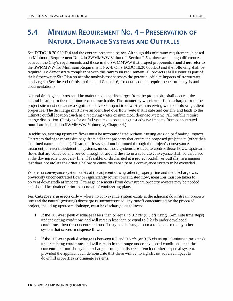
5.4 MINIMUM REQUIREMENT NO. 4 – PRESERVATION OF
NATURAL DRAINAGE SYSTEMS AND OUTFALLS See ECDC 18.30.060.D.4 and the content presented below. Although this minimum requirement is based on Minimum Requirement No. 4 in SWMMWW Volume I, Section 2.5.4, there are enough differences between the City’s requirements and those in the SWMMWW that project proponents should not refer to the SWMMWW for Minimum Requirement No. 4. Only ECDC 18.30.060.D.3 and the following shall be required. To demonstrate compliance with this minimum requirement, all projects shall submit as part of their Stormwater Site Plan an off-site analysis that assesses the potential off-site impacts of stormwater discharges. (See the end of this section, and Chapter 6, for details on the requirements for analysis and documentation.)
Natural drainage patterns shall be maintained, and discharges from the project site shall occur at the natural location, to the maximum extent practicable. The manner by which runoff is discharged from the project site must not cause a significant adverse impact to downstream receiving waters or down gradient properties. The discharge must have an identified overflow route that is safe and certain, and leads to the ultimate outfall location (such as a receiving water or municipal drainage system). All outfalls require energy dissipation. (Designs for outfall systems to protect against adverse impacts from concentrated runoff are included in SWMMWW Volume V, Chapter 4.)
In addition, existing upstream flows must be accommodated without causing erosion or flooding impacts. Upstream drainage means drainage from adjacent property that enters the proposed project site (other than a defined natural channel). Upstream flows shall not be routed through the project’s conveyance, treatment, or retention/detention systems, unless those systems are sized to control those flows. Upstream flows that are collected and routed through or around the site in a separate conveyance shall be dispersed at the downgradient property line, if feasible, or discharged at a project outfall (or outfalls) in a manner that does not violate the criteria below or cause the capacity of a conveyance system to be exceeded.
Where no conveyance system exists at the adjacent downgradient property line and the discharge was previously unconcentrated flow or significantly lower concentrated flow, measures must be taken to prevent downgradient impacts. Drainage easements from downstream property owners may be needed and should be obtained prior to approval of engineering plans.
For Category 2 projects only – where no conveyance system exists at the adjacent downstream property line and the natural (existing) discharge is unconcentrated, any runoff concentrated by the proposed project, including upstream drainage, must be discharged as follows:
1. If the 100-year peak discharge is less than or equal to 0.2 cfs (0.3 cfs using 15-minute time steps) under existing conditions and will remain less than or equal to 0.2 cfs under developed conditions, then the concentrated runoff may be discharged onto a rock pad or to any other system that serves to disperse flows.
2. If the 100-year peak discharge is between 0.2 and 0.5 cfs (or 0.75 cfs using 15-minute time steps) under existing conditions and will remain in that range under developed conditions, then the concentrated runoff may be discharged through a dispersal trench or other dispersal system, provided the applicant can demonstrate that there will be no significant adverse impact to downhill properties or drainage systems.
JUNE 2017 EDMONDS STORMWATER ADDENDUM
5. PROJECT MINIMUM REQUIREMENTS 15
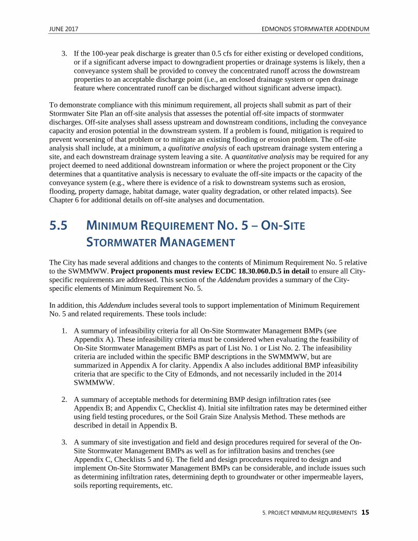
3. If the 100-year peak discharge is greater than 0.5 cfs for either existing or developed conditions, or if a significant adverse impact to downgradient properties or drainage systems is likely, then a conveyance system shall be provided to convey the concentrated runoff across the downstream properties to an acceptable discharge point (i.e., an enclosed drainage system or open drainage feature where concentrated runoff can be discharged without significant adverse impact).
To demonstrate compliance with this minimum requirement, all projects shall submit as part of their Stormwater Site Plan an off-site analysis that assesses the potential off-site impacts of stormwater discharges. Off-site analyses shall assess upstream and downstream conditions, including the conveyance capacity and erosion potential in the downstream system. If a problem is found, mitigation is required to prevent worsening of that problem or to mitigate an existing flooding or erosion problem. The off-site analysis shall include, at a minimum, a qualitative analysis of each upstream drainage system entering a site, and each downstream drainage system leaving a site. A quantitative analysis may be required for any project deemed to need additional downstream information or where the project proponent or the City determines that a quantitative analysis is necessary to evaluate the off-site impacts or the capacity of the conveyance system (e.g., where there is evidence of a risk to downstream systems such as erosion, flooding, property damage, habitat damage, water quality degradation, or other related impacts). See Chapter 6 for additional details on off-site analyses and documentation.
5.5 MINIMUM REQUIREMENT NO. 5 – ON-SITE
STORMWATER MANAGEMENT The City has made several additions and changes to the contents of Minimum Requirement No. 5 relative to the SWMMWW. Project proponents must review ECDC 18.30.060.D.5 in detail to ensure all City-specific requirements are addressed. This section of the Addendum provides a summary of the City-specific elements of Minimum Requirement No. 5.
In addition, this Addendum includes several tools to support implementation of Minimum Requirement No. 5 and related requirements. These tools include:
1. A summary of infeasibility criteria for all On-Site Stormwater Management BMPs (see Appendix A). These infeasibility criteria must be considered when evaluating the feasibility of On-Site Stormwater Management BMPs as part of List No. 1 or List No. 2. The infeasibility criteria are included within the specific BMP descriptions in the SWMMWW, but are summarized in Appendix A for clarity. Appendix A also includes additional BMP infeasibility criteria that are specific to the City of Edmonds, and not necessarily included in the 2014 SWMMWW.
2. A summary of acceptable methods for determining BMP design infiltration rates (see Appendix B; and Appendix C, Checklist 4). Initial site infiltration rates may be determined either using field testing procedures, or the Soil Grain Size Analysis Method. These methods are described in detail in Appendix B.
3. A summary of site investigation and field and design procedures required for several of the On-Site Stormwater Management BMPs as well as for infiltration basins and trenches (see Appendix C, Checklists 5 and 6). The field and design procedures required to design and implement On-Site Stormwater Management BMPs can be considerable, and include issues such as determining infiltration rates, determining depth to groundwater or other impermeable layers, soils reporting requirements, etc.
EDMONDS STORMWATER ADDENDUM JUNE 2017
16 5. PROJECT MINIMUM REQUIREMENTS
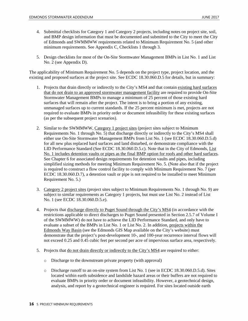
4. Submittal checklists for Category 1 and Category 2 projects, including notes on project site, soil, and BMP design information that must be documented and submitted to the City to meet the City of Edmonds and SWMMWW requirements related to Minimum Requirement No. 5 (and other minimum requirements. See Appendix C, Checklists 1 through 3.
5. Design checklists for most of the On-Site Stormwater Management BMPs in List No. 1 and List No. 2 (see Appendix D).
The applicability of Minimum Requirement No. 5 depends on the project type, project location, and the existing and proposed surfaces at the project site. See ECDC 18.30.060.D.5 for details, but in summary:
1. Projects that drain directly or indirectly to the City’s MS4 and that contain existing hard surfaces that do not drain to an approved stormwater management facility are required to provide On-Site Stormwater Management BMPs to manage a minimum of 25 percent of those existing hard surfaces that will remain after the project. The intent is to bring a portion of any existing, unmanaged surfaces up to current standards. If the 25 percent minimum is met, projects are not required to evaluate BMPs in priority order or document infeasibility for these existing surfaces (as per the subsequent project scenarios).
2. Similar to the SWMMWW, Category 1 project sites (project sites subject to Minimum Requirements No. 1 through No. 5) that discharge directly or indirectly to the City’s MS4 shall either use On-Site Stormwater Management BMPs from List No. 1 (see ECDC 18.30.060.D.5.d) for all new plus replaced hard surfaces and land disturbed, or demonstrate compliance with the LID Performance Standard (See ECDC 18.30.060.D.5.c). Note that in the City of Edmonds, List No. 1 includes detention vaults or pipes as the final BMP option for roofs and other hard surfaces. See Chapter 6 for associated design requirements for detention vaults and pipes, including simplified sizing methods for meeting Minimum Requirement No. 5. (Note also that if the project is required to construct a flow control facility to comply with Minimum Requirement No. 7 (per ECDC 18.30.060.D.7), a detention vault or pipe is not required to be installed to meet Minimum Requirement No. 5.)
3. Category 2 project sites (project sites subject to Minimum Requirements No. 1 through No. 9) are subject to similar requirements as Category 1 projects, but must use List No. 2 instead of List No. 1 (see ECDC 18.30.060.D.5.e).
4. Projects that discharge directly to Puget Sound through the City’s MS4 (in accordance with the restrictions applicable to direct discharges to Puget Sound presented in Section 2.5.7 of Volume I of the SWMMWW) do not have to achieve the LID Performance Standard, and only have to evaluate a subset of the BMPs in List No. 1 or List No. 2. In addition, projects within the Edmonds Way Basin (see the Edmonds GIS Map available on the City’s website) must demonstrate that the project’s post-development 10-, and 100-year recurrence interval flows will not exceed 0.25 and 0.45 cubic feet per second per acre of impervious surface area, respectively.
5. Projects that do not drain directly or indirectly to the City’s MS4 are required to either:
o Discharge to the downstream private property (with approval)
o Discharge runoff to an on-site system from List No. 1 (see in ECDC 18.30.060.D.5.d). Sites located within earth subsidence and landslide hazard areas or their buffers are not required to evaluate BMPs in priority order or document infeasibility. However, a geotechnical design, analysis, and report by a geotechnical engineer is required. For sites located outside earth
JUNE 2017 EDMONDS STORMWATER ADDENDUM
5. PROJECT MINIMUM REQUIREMENTS 17
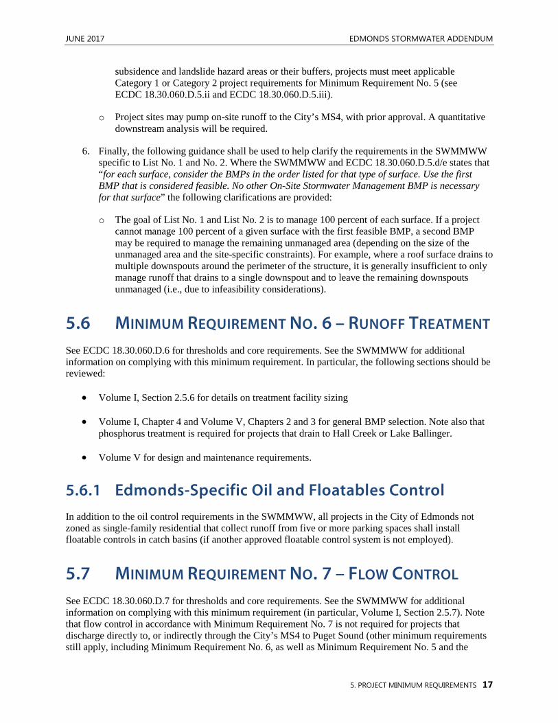
subsidence and landslide hazard areas or their buffers, projects must meet applicable Category 1 or Category 2 project requirements for Minimum Requirement No. 5 (see ECDC 18.30.060.D.5.ii and ECDC 18.30.060.D.5.iii).
o Project sites may pump on-site runoff to the City’s MS4, with prior approval. A quantitative downstream analysis will be required.
6. Finally, the following guidance shall be used to help clarify the requirements in the SWMMWW specific to List No. 1 and No. 2. Where the SWMMWW and ECDC 18.30.060.D.5.d/e states that “for each surface, consider the BMPs in the order listed for that type of surface. Use the first BMP that is considered feasible. No other On-Site Stormwater Management BMP is necessary for that surface” the following clarifications are provided:
o The goal of List No. 1 and List No. 2 is to manage 100 percent of each surface. If a project cannot manage 100 percent of a given surface with the first feasible BMP, a second BMP may be required to manage the remaining unmanaged area (depending on the size of the unmanaged area and the site-specific constraints). For example, where a roof surface drains to multiple downspouts around the perimeter of the structure, it is generally insufficient to only manage runoff that drains to a single downspout and to leave the remaining downspouts unmanaged (i.e., due to infeasibility considerations).
5.6 MINIMUM REQUIREMENT NO. 6 – RUNOFF TREATMENT See ECDC 18.30.060.D.6 for thresholds and core requirements. See the SWMMWW for additional information on complying with this minimum requirement. In particular, the following sections should be reviewed:
• Volume I, Section 2.5.6 for details on treatment facility sizing
• Volume I, Chapter 4 and Volume V, Chapters 2 and 3 for general BMP selection. Note also that phosphorus treatment is required for projects that drain to Hall Creek or Lake Ballinger.
• Volume V for design and maintenance requirements.
5.6.1 Edmonds-Specific Oil and Floatables Control In addition to the oil control requirements in the SWMMWW, all projects in the City of Edmonds not zoned as single-family residential that collect runoff from five or more parking spaces shall install floatable controls in catch basins (if another approved floatable control system is not employed).
5.7 MINIMUM REQUIREMENT NO. 7 – FLOW CONTROL See ECDC 18.30.060.D.7 for thresholds and core requirements. See the SWMMWW for additional information on complying with this minimum requirement (in particular, Volume I, Section 2.5.7). Note that flow control in accordance with Minimum Requirement No. 7 is not required for projects that discharge directly to, or indirectly through the City’s MS4 to Puget Sound (other minimum requirements still apply, including Minimum Requirement No. 6, as well as Minimum Requirement No. 5 and the
EDMONDS STORMWATER ADDENDUM JUNE 2017
18 5. PROJECT MINIMUM REQUIREMENTS
Edmonds Way direct discharge requirements). See ECDC 18.30.060.D.5.b.iv and Section 2.5.7 of Volume I of the SWMMWW for additional restrictions applicable to direct discharges to Puget Sound.
In addition, the following information may be useful in determining the applicability of Minimum Requirement No. 7, specifically per the 100-year flow frequency threshold outlined in ECDC 18.30.060.D.7.b.iii:
Calculations to determine whether a project exceeds the 0.10 cubic feet per second (cfs), using a 1-hour time step (or 0.15 cfs using a 15-minute time step) increase in the 100-year recurrence interval flow must be performed individually for each project using an approved continuous simulation runoff model. The calculation will compare runoff in the post development site to the pre-development land cover. Pre-development, for this activity only, is the lower runoff of the pre project condition, or the site on July 6, 1977 (the effective date of the City’s first drainage control ordinance). The unique site, soil, precipitation, and other project-specific factors will ultimately determine whether this threshold is exceeded. Nonetheless, the following general guidelines (based on hypothetical site designs) may be used to help identify the likelihood of this threshold being exceeded. The following land use changes are likely to exceed this threshold under certain conditions:
• Converting approximately 5,000 square feet of forest to hard surface
• Converting approximately 5,000 square feet of pasture to hard surface
• Converting approximately 0.25 acres of forest to landscape surface
• Converting approximately 1.25 acres of forest to pasture surfaces (in till soil conditions)
5.8 MINIMUM REQUIREMENT NO. 8 – WETLAND PROTECTION
See ECDC 18.30.060.D.8 and SWMMWW Volume I, Section 2.5.8. See also SWMMWW Volume I, Appendix I-D Guide Sheets No. 1 through No. 3.
5.9 MINIMUM REQUIREMENT NO. 9 – OPERATION AND MAINTENANCE
See ECDC 18.30.060.D.9. See also the submittal checklists provided in Appendix C, Checklists 1 through 3 (also referenced previously as part of Minimum Requirements No. 1 and No. 5) for notes about submittal requirements related to the required operation and maintenance manual.
JUNE 2017 EDMONDS STORMWATER ADDENDUM
6. ADDITIONAL REQUIREMENTS 19
6 ADDITIONAL REQUIREMENTS This chapter includes additional requirements that are either not included in the SWMMWW, or that are supplemental to the information provided in the SWMMWW. Specifically, this chapter addresses:
1. Additional requirements pertaining to Construction SWPPP Element No. 13 – Protect Low Impact Development BMPs (required in the SWMMWW, but not outlined in this level of detail).
2. Details on the off-site analyses and documentation required to comply with Minimum Requirement No. 4, Preservation of Natural Drainage Systems and Outfalls (City of Edmonds specific).
3. Design requirements for detention vaults and pipes when used to meet Minimum Requirement No. 5.
4. Information on Underground Injection Controls (UICs).
6.1 PROTECTION OF LID FACILITIES DURING
CONSTRUCTION To ensure that LID stormwater facilities and BMPs will be fully functional after construction, it is important to protect these BMPs during construction activities. Protecting native soil and vegetation, minimizing soil compaction, and retaining the hydrologic function of LID BMPs during the site preparation and construction phases are some of the most important practices during the development process.
The purpose of this section is to provide designers, builders, and inspectors with guidance and tools for meeting Minimum Requirement No. 2, Element No. 13 – Protect Low Impact Development BMPs. This section does not provide guidance on construction or design of LID BMPs (see SWMMWW Volume III and Volume V), or cover all Construction SWPPP practices (see SWMMWW Volume II), but rather focuses on how to most efficiently reduce impacts on LID BMPs specifically during construction. The practices specified in this section must be applied to protect LID BMPs, unless the given practice does not apply to the project site conditions or activities.
6.1.1 General Erosion and Sediment Control BMPs Applicable to LID
Overall Construction Stormwater Pollution Prevention Plan (SWPPP) requirements are specified in Chapter 5, Minimum Requirement No. 2 and SWMMWW Volume II. In general, Construction SWPPP BMPs limit the impact of site disturbance, erosion, and sediment deposition during construction. Some Construction SWPPP BMPs focus on providing a physical barrier or deterrent to help minimize construction-related site disturbance and/or erosion, while other Construction SWPPP BMPs help protect the site from concentrated (i.e., erosive) flows. General Construction SWPPP BMPs and their application
EDMONDS STORMWATER ADDENDUM JUNE 2017
20 6. ADDITIONAL REQUIREMENTS
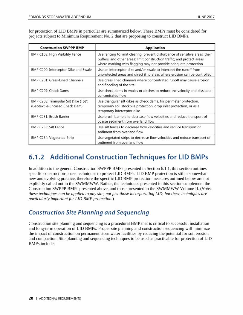
for protection of LID BMPs in particular are summarized below. These BMPs must be considered for projects subject to Minimum Requirement No. 2 that are proposing to construct LID BMPs.
Construction SWPPP BMP Application
BMP C103: High Visibility Fence Use fencing to limit clearing; prevent disturbance of sensitive areas, their buffers, and other areas; limit construction traffic; and protect areas where marking with flagging may not provide adequate protection
BMP C200: Interceptor Dike and Swale Use an interceptor dike and/or swale to intercept the runoff from unprotected areas and direct it to areas where erosion can be controlled
BMP C201: Grass-Lined Channels Use grass lined channels where concentrated runoff may cause erosion and flooding of the site
BMP C207: Check Dams Use check dams in swales or ditches to reduce the velocity and dissipate concentrated flow
BMP C208: Triangular Silt Dike (TSD) (Geotextile-Encased Check Dam)
Use triangular silt dikes as check dams, for perimeter protection, temporary soil stockpile protection, drop inlet protection, or as a temporary interceptor dike
BMP C231: Brush Barrier Use brush barriers to decrease flow velocities and reduce transport of coarse sediment from overland flow
BMP C233: Silt Fence Use silt fences to decrease flow velocities and reduce transport of sediment from overland flow
BMP C234: Vegetated Strip Use vegetated strips to decrease flow velocities and reduce transport of sediment from overland flow
6.1.2 Additional Construction Techniques for LID BMPs In addition to the general Construction SWPPP BMPs presented in Section 6.1.1, this section outlines specific construction-phase techniques to protect LID BMPs. LID BMP protection is still a somewhat new and evolving practice, therefore the specific LID BMP protection measures outlined below are not explicitly called out in the SWMMWW. Rather, the techniques presented in this section supplement the Construction SWPPP BMPs presented above, and those presented in the SWMMWW Volume II. (Note: these techniques can be applied to any site, not just those incorporating LID, but these techniques are particularly important for LID BMP protection.)
Construction Site Planning and Sequencing
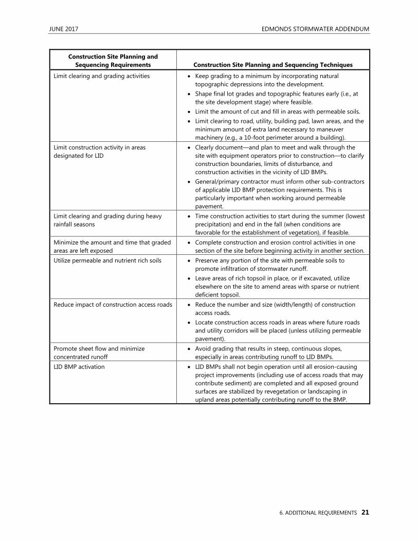
Construction site planning and sequencing is a procedural BMP that is critical to successful installation and long-term operation of LID BMPs. Proper site planning and construction sequencing will minimize the impact of construction on permanent stormwater facilities by reducing the potential for soil erosion and compaction. Site planning and sequencing techniques to be used as practicable for protection of LID BMPs include:
JUNE 2017 EDMONDS STORMWATER ADDENDUM
6. ADDITIONAL REQUIREMENTS 21
Construction Site Planning and Sequencing Requirements Construction Site Planning and Sequencing Techniques
Limit clearing and grading activities • Keep grading to a minimum by incorporating natural topographic depressions into the development.
• Shape final lot grades and topographic features early (i.e., at the site development stage) where feasible.
• Limit the amount of cut and fill in areas with permeable soils. • Limit clearing to road, utility, building pad, lawn areas, and the
minimum amount of extra land necessary to maneuver machinery (e.g., a 10-foot perimeter around a building).
Limit construction activity in areas designated for LID
• Clearly document—and plan to meet and walk through the site with equipment operators prior to construction—to clarify construction boundaries, limits of disturbance, and construction activities in the vicinity of LID BMPs.
• General/primary contractor must inform other sub-contractors of applicable LID BMP protection requirements. This is particularly important when working around permeable pavement.
Limit clearing and grading during heavy rainfall seasons
• Time construction activities to start during the summer (lowest precipitation) and end in the fall (when conditions are favorable for the establishment of vegetation), if feasible.
Minimize the amount and time that graded areas are left exposed
• Complete construction and erosion control activities in one section of the site before beginning activity in another section.
Utilize permeable and nutrient rich soils • Preserve any portion of the site with permeable soils to promote infiltration of stormwater runoff.
• Leave areas of rich topsoil in place, or if excavated, utilize elsewhere on the site to amend areas with sparse or nutrient deficient topsoil.
Reduce impact of construction access roads • Reduce the number and size (width/length) of construction access roads.
• Locate construction access roads in areas where future roads and utility corridors will be placed (unless utilizing permeable pavement).
Promote sheet flow and minimize concentrated runoff
• Avoid grading that results in steep, continuous slopes, especially in areas contributing runoff to LID BMPs.
LID BMP activation • LID BMPs shall not begin operation until all erosion-causing project improvements (including use of access roads that may contribute sediment) are completed and all exposed ground surfaces are stabilized by revegetation or landscaping in upland areas potentially contributing runoff to the BMP.
EDMONDS STORMWATER ADDENDUM JUNE 2017
22 6. ADDITIONAL REQUIREMENTS
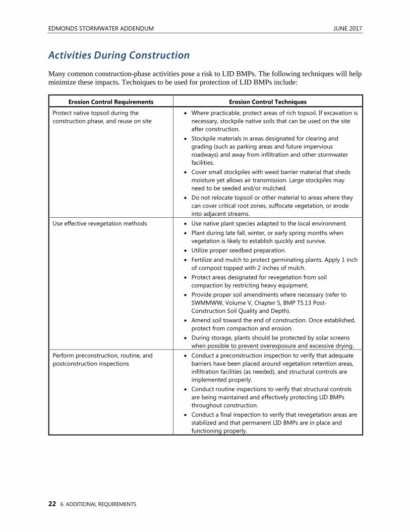
Activities During Construction
Many common construction-phase activities pose a risk to LID BMPs. The following techniques will help minimize these impacts. Techniques to be used for protection of LID BMPs include:
Erosion Control Requirements Erosion Control Techniques
Protect native topsoil during the construction phase, and reuse on site
• Where practicable, protect areas of rich topsoil. If excavation is necessary, stockpile native soils that can be used on the site after construction.
• Stockpile materials in areas designated for clearing and grading (such as parking areas and future impervious roadways) and away from infiltration and other stormwater facilities.
• Cover small stockpiles with weed barrier material that sheds moisture yet allows air transmission. Large stockpiles may need to be seeded and/or mulched.
• Do not relocate topsoil or other material to areas where they can cover critical root zones, suffocate vegetation, or erode into adjacent streams.
Use effective revegetation methods • Use native plant species adapted to the local environment. • Plant during late fall, winter, or early spring months when
vegetation is likely to establish quickly and survive. • Utilize proper seedbed preparation. • Fertilize and mulch to protect germinating plants. Apply 1 inch
of compost topped with 2 inches of mulch. • Protect areas designated for revegetation from soil
compaction by restricting heavy equipment. • Provide proper soil amendments where necessary (refer to
SWMMWW, Volume V, Chapter 5, BMP T5.13 Post-Construction Soil Quality and Depth).
• Amend soil toward the end of construction. Once established, protect from compaction and erosion.
• During storage, plants should be protected by solar screens when possible to prevent overexposure and excessive drying.
Perform preconstruction, routine, and postconstruction inspections
• Conduct a preconstruction inspection to verify that adequate barriers have been placed around vegetation retention areas, infiltration facilities (as needed), and structural controls are implemented properly.
• Conduct routine inspections to verify that structural controls are being maintained and effectively protecting LID BMPs throughout construction.
• Conduct a final inspection to verify that revegetation areas are stabilized and that permanent LID BMPs are in place and functioning properly.
JUNE 2017 EDMONDS STORMWATER ADDENDUM
6. ADDITIONAL REQUIREMENTS 23
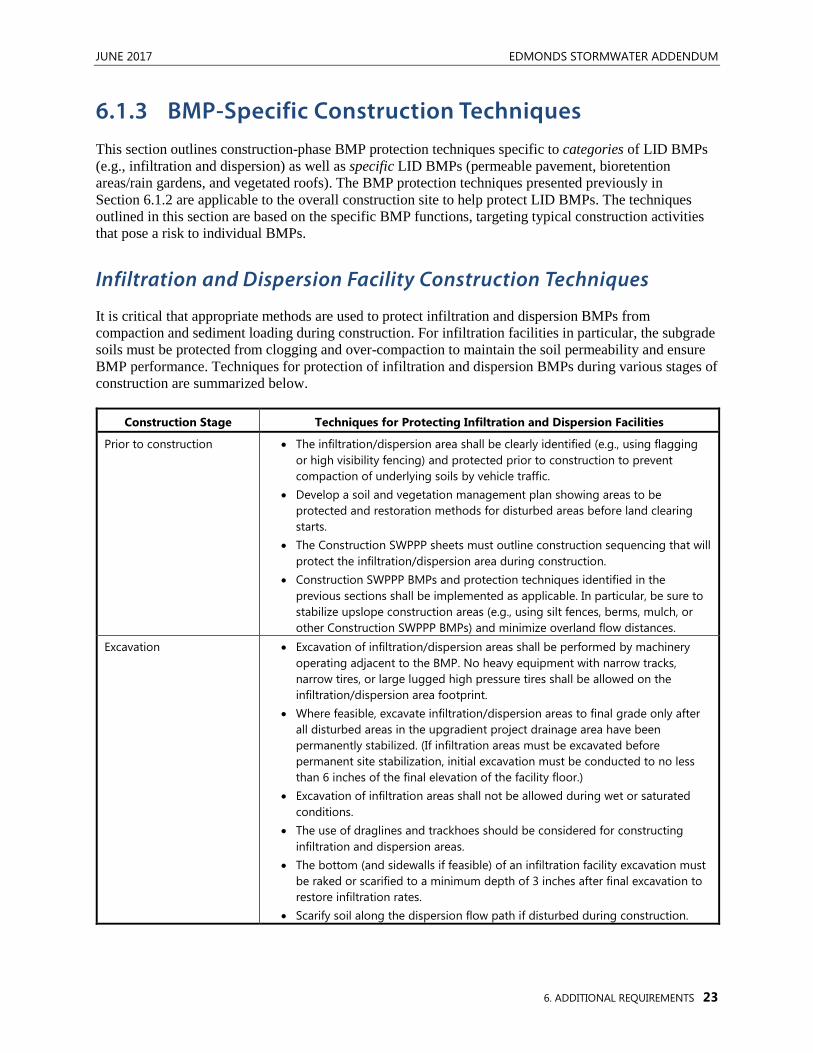
6.1.3 BMP-Specific Construction Techniques This section outlines construction-phase BMP protection techniques specific to categories of LID BMPs (e.g., infiltration and dispersion) as well as specific LID BMPs (permeable pavement, bioretention areas/rain gardens, and vegetated roofs). The BMP protection techniques presented previously in Section 6.1.2 are applicable to the overall construction site to help protect LID BMPs. The techniques outlined in this section are based on the specific BMP functions, targeting typical construction activities that pose a risk to individual BMPs.
Infiltration and Dispersion Facility Construction Techniques
It is critical that appropriate methods are used to protect infiltration and dispersion BMPs from compaction and sediment loading during construction. For infiltration facilities in particular, the subgrade soils must be protected from clogging and over-compaction to maintain the soil permeability and ensure BMP performance. Techniques for protection of infiltration and dispersion BMPs during various stages of construction are summarized below.
Construction Stage Techniques for Protecting Infiltration and Dispersion Facilities
Prior to construction • The infiltration/dispersion area shall be clearly identified (e.g., using flagging or high visibility fencing) and protected prior to construction to prevent compaction of underlying soils by vehicle traffic.
• Develop a soil and vegetation management plan showing areas to be protected and restoration methods for disturbed areas before land clearing starts.
• The Construction SWPPP sheets must outline construction sequencing that will protect the infiltration/dispersion area during construction.
• Construction SWPPP BMPs and protection techniques identified in the previous sections shall be implemented as applicable. In particular, be sure to stabilize upslope construction areas (e.g., using silt fences, berms, mulch, or other Construction SWPPP BMPs) and minimize overland flow distances.
Excavation • Excavation of infiltration/dispersion areas shall be performed by machinery operating adjacent to the BMP. No heavy equipment with narrow tracks, narrow tires, or large lugged high pressure tires shall be allowed on the infiltration/dispersion area footprint.
• Where feasible, excavate infiltration/dispersion areas to final grade only after all disturbed areas in the upgradient project drainage area have been permanently stabilized. (If infiltration areas must be excavated before permanent site stabilization, initial excavation must be conducted to no less than 6 inches of the final elevation of the facility floor.)
• Excavation of infiltration areas shall not be allowed during wet or saturated conditions.
• The use of draglines and trackhoes should be considered for constructing infiltration and dispersion areas.
• The bottom (and sidewalls if feasible) of an infiltration facility excavation must be raked or scarified to a minimum depth of 3 inches after final excavation to restore infiltration rates.
• Scarify soil along the dispersion flow path if disturbed during construction.
EDMONDS STORMWATER ADDENDUM JUNE 2017
24 6. ADDITIONAL REQUIREMENTS
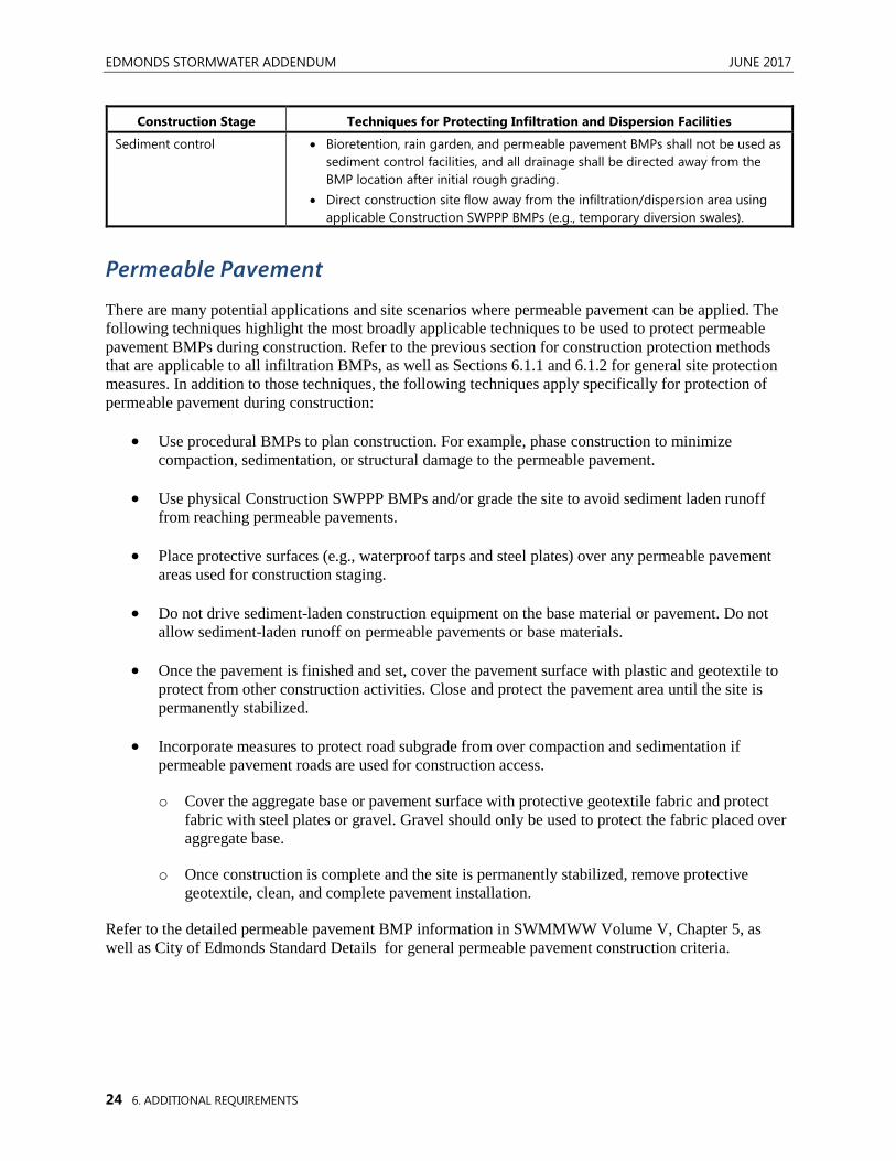
Construction Stage Techniques for Protecting Infiltration and Dispersion Facilities
Sediment control • Bioretention, rain garden, and permeable pavement BMPs shall not be used as sediment control facilities, and all drainage shall be directed away from the BMP location after initial rough grading.
• Direct construction site flow away from the infiltration/dispersion area using applicable Construction SWPPP BMPs (e.g., temporary diversion swales).
Permeable Pavement
There are many potential applications and site scenarios where permeable pavement can be applied. The following techniques highlight the most broadly applicable techniques to be used to protect permeable pavement BMPs during construction. Refer to the previous section for construction protection methods that are applicable to all infiltration BMPs, as well as Sections 6.1.1 and 6.1.2 for general site protection measures. In addition to those techniques, the following techniques apply specifically for protection of permeable pavement during construction:
• Use procedural BMPs to plan construction. For example, phase construction to minimize compaction, sedimentation, or structural damage to the permeable pavement.
• Use physical Construction SWPPP BMPs and/or grade the site to avoid sediment laden runoff from reaching permeable pavements.
• Place protective surfaces (e.g., waterproof tarps and steel plates) over any permeable pavement areas used for construction staging.
• Do not drive sediment-laden construction equipment on the base material or pavement. Do not allow sediment-laden runoff on permeable pavements or base materials.
• Once the pavement is finished and set, cover the pavement surface with plastic and geotextile to protect from other construction activities. Close and protect the pavement area until the site is permanently stabilized.
• Incorporate measures to protect road subgrade from over compaction and sedimentation if permeable pavement roads are used for construction access.
o Cover the aggregate base or pavement surface with protective geotextile fabric and protect fabric with steel plates or gravel. Gravel should only be used to protect the fabric placed over aggregate base.
o Once construction is complete and the site is permanently stabilized, remove protective geotextile, clean, and complete pavement installation.
Refer to the detailed permeable pavement BMP information in SWMMWW Volume V, Chapter 5, as well as City of Edmonds Standard Details for general permeable pavement construction criteria.
JUNE 2017 EDMONDS STORMWATER ADDENDUM
6. ADDITIONAL REQUIREMENTS 25
Bioretention Areas and Rain Gardens
As with permeable pavements, there are many potential applications and site scenarios where bioretention and rain garden BMPs can be applied. The following techniques highlight the most broadly applicable techniques to be used to protect bioretention and rain garden BMPs during construction. Refer to the beginning of this section for construction protection methods that are applicable to all infiltration BMPs, as well as Sections 6.1.1 and 6.1.2 for general site protection measures. In addition to those techniques, the following techniques apply specifically for protection of bioretention and rain garden BMPs during construction:
• Excavation:
o If machinery must operate in the bioretention area for excavation, use lightweight, low ground-contact pressure equipment and rip the base at completion to scarify soil to a minimum of 12 inches.
• Protect bioretention soil mix from compaction during construction
o Do not place bioretention soil mix if saturated or during wet periods.
o Check for compaction prior to planting. If compaction occurs, aerate the bioretention soil and then proceed to plant.
Refer to the detailed bioretention and rain garden BMP information in SWMMWW Volume V, Chapter 7, as well as City of Edmonds Standard Details for general bioretention and rain garden construction criteria.
Vegetated Roofs
The following additional techniques apply for protection of vegetated roof facilities during construction:
• Because of their location and complexity, vegetated roofs typically require more planning and coordination effort relative to ground-level landscaping. For new construction, a critical path approach is highly recommended to establish the sequence of tasks for construction of the vegetated roof system.
• During construction, it is vitally important that the waterproof membrane be protected once installed. The waterproofing should be tested prior to placement of the growth media and other subsequent vegetated roof materials.
Refer to the detailed vegetated roof BMP information in SWMMWW Volume V, Chapter 5 for general construction criteria.
6.2 OFF-SITE ANALYSES AND DOCUMENTATION All projects subject to Minimum Requirement No. 4 shall submit as part of their Stormwater Site Plan an off-site analysis that assesses the potential off-site impacts of stormwater discharges. The following sections detail the analysis and documentation requirements for Category 1 and Category 2 projects.
EDMONDS STORMWATER ADDENDUM JUNE 2017
26 6. ADDITIONAL REQUIREMENTS
6.2.1 Category 1 Projects Category 1 projects shall submit a qualitative analysis of potential off-site impacts of stormwater discharges for each upstream drainage system entering a site, and each downstream drainage system leaving a site. The upstream analysis shall identify and describe points where water enters the site. Any upstream contributing areas shall be identified and mapped in the project Stormwater Site Plan submittal. The downstream analysis shall extend from the project site to the receiving water, or up to one-quarter mile, whichever is less. In many cases, runoff that leaves a project site will enter the City’s MS4 within one-quarter mile. In these instances, the project must evaluate and document downstream conditions up to and including runoff entry into the City’s MS4. In addition, the project proponent shall consult with the City to determine whether the MS4 has any existing or anticipated capacity issues downstream of the proposed project.
The qualitative analysis shall identify where and how stormwater runoff will leave the proposed development site, and describe conditions downstream of the site including any existing or anticipated future problem areas (e.g., spot flooding, property damage, erosion issues, capacity-limited drainage systems, etc.). The qualitative analysis must be sufficient for the City to evaluate whether the project has adequately identified potential impacts and whether proposed mitigation measures are supported by the analysis. Some “rough” quantitative analyses, which can be based on non-surveyed field data, may be necessary as part of the qualitative analysis to adequately describe or document the extent of observed problem areas. Note that any off-site field visits should be conducted during winter months and after significant precipitation events to identify seasonal issues such as flooding, capacity constraints, or surface seeps or other indicators of near surface groundwater.
A quantitative analysis may also be required for any project where the project proponent or the City determines that a more thorough analysis is necessary to evaluate the off-site impacts or the capacity of the conveyance system (e.g., where there is evidence of a risk to downstream systems such as erosion, flooding, property damage, habitat damage, water quality degradation, or other related impacts). A quantitative analysis may include calculations and/or modeling analyses of on-site and off-site water quality, erosion, slope stability, and other drainage-related impacts that may be caused or aggravated by a proposed project.
6.2.2 Category 2 Projects All Category 2 projects shall submit a qualitative analysis of potential off-site impacts of stormwater discharges that extend downstream from the site to the receiving water. (If the ultimate discharge point is to Puget Sound via a culvert owned by BNSF Railway, the analysis must be followed through the drainage system all the way to Puget Sound.) A quantitative analysis may also be required for any project deemed to need additional downstream information or where the project engineer or the City determines that a quantitative analysis is necessary to evaluate the off-site impacts or the capacity of the conveyance system (e.g., where there are known capacity issues or where there is evidence of a risk to downstream systems such as erosion, flooding, property damage, habitat damage, water quality degradation, or other related impacts).
The qualitative analysis must be sufficient for the City to evaluate whether the project has adequately identified potential impacts and whether proposed mitigation measures are supported by the analysis. Some “rough” quantitative analysis, which can be based on non-surveyed field data, may be required at this stage. A downstream analysis of the project for a minimum of one-quarter of a mile is required. The analysis must also extend upstream to a point beyond any backwater effects caused by the project. The
JUNE 2017 EDMONDS STORMWATER ADDENDUM
6. ADDITIONAL REQUIREMENTS 27
analysis must include field-inspection of all existing stormwater drainage systems downstream from the project and a determination of whether the capacity of the drainage system(s) is adequate to handle the existing flows, flows generated by the proposed project, and any overflow. Adequacy will be evaluated based on conveyance capacity, flooding problems, erosion damage or potential, amount of freeboard in channel and pipes, and storage potential within the system. Note that site visits should be conducted during winter months and after significant precipitation events to identify undocumented surface seeps or other indicators of near surface groundwater. See the end of this section for specific topics to be discussed in the qualitative analysis.
When deemed necessary by the project engineer or required by the City, a quantitative analysis shall include the qualitative analysis describe above, as well as quantitative calculations and/or modeling analyses of on-site and off-site water quality, erosion, slope stability, and other drainage-related impacts that may be caused or aggravated by a proposed project. Measures for preventing impacts and for not aggravating existing impacts shall also be identified. (“Aggravating existing impacts” means increasing the frequency of occurrence and/or severity of an impact.) The analysis shall document how temporary and permanent flow control and water quality control measures identified in the Stormwater Site Plan will mitigate the potential to create new problems or aggravate existing conditions. In many cases, design of flow control and water quality systems according to the procedures contained in this Addendum and the SWMMWW will be adequate demonstration of mitigation. However, upon review of this analysis and the severity of an existing problem, the City may require more detailed analysis and/or additional mitigation measures. In general, all existing and proposed off-site surface water conveyance systems shall be sized to convey flows without surcharging the City’s storm system (or BNSF culverts under the railroad tracks, if applicable).
Both the qualitative analysis and the quantitative analyses (when required) shall include descriptions and/or analyses of the following items. The descriptions shall identify existing or potential problem areas, and whether adequate mitigation can be identified (or whether more detailed quantitative analysis is necessary). References to other Stormwater Site Plan sections (e.g., facility sizing, conveyance, attachments and appendices, etc.) are encouraged to reduce plan redundancy, as long as all of the required Stormwater Site Plan issues are clearly presented:
• Describe the drainage system between the site and the receiving surface waters. Provide information on pipe sizes, channel characteristics, and drainage structures. Describe emergency services located along the flow path (e.g., fire/police stations, hospitals). Describe environmentally sensitive areas, such as wetlands, etc.
• Describe the upstream drainage tributary to the project. Describe any bypass drainage from the project which will not be controlled.
• The bulk of the analysis shall focus on highlights of important considerations from the project overview and off-site analysis sections related to the drainage system and potential problems or concerns. Existing and potential impacts to be evaluated and mitigated shall include, but not be limited to:
o Conveyance system capacity issues.
o Flooding or bank overtopping.
o Upland erosion impacts, including slope stability and landslide hazards.
o Stream channel erosion (at the outfall location and to the downstream limit of analysis).
EDMONDS STORMWATER ADDENDUM JUNE 2017
28 6. ADDITIONAL REQUIREMENTS
o Violations of surface water quality standards as identified in a Basin Plan or a TMDL/Water Cleanup Plan (e.g., for Lake Ballinger).
o For each existing or potential problem, document: the magnitude of damage caused by the problem, the general frequency and duration, current mitigation of the problem (if any), the likely or possible cause of the problem, and whether the project is likely to aggravate the problem or create a new one.
• Determine whether the project is within any other critical areas or their buffers as defined in ECDC, and whether any additional requirements apply.
• All areas pertinent to the analyses such as site boundaries, study area boundaries, streets and prominent features, downstream flow path, potential/existing problems, etc. shall be keyed to features shown on the project map(s).
6.3 DESIGN REQUIREMENTS FOR DETENTION VAULTS AND
PIPES This section includes design requirements and associated information for detention vaults and detention pipes. The focus of this section is on the use of detention vaults and pipes to meet Minimum Requirement No. 5. For other design applications (e.g., to meet Minimum Requirement No. 7), designers must refer to the SWMMWW.
For Category 1 and 2 projects that must comply with Minimum Requirement No. 5, the final option that is available for roofs and other hard surfaces under List No. 1 and List No. 2 (per ECDC 18.30.060.D.5 [d] or [e]) is the use of detention vaults or detention pipes. When using detention vaults or pipes to comply with Minimum Requirement No. 5 using List No. 1 or List No. 2 in the City of Edmonds, the following requirements apply. Note that if the project is required to construct a flow control facility to comply with Minimum Requirement No. 7 (per ECDC 18.30.060.D.7), a detention vault is not required to be installed to meet Minimum Requirement No. 5.
The City may waive the requirement to install a detention vault or pipe if the downstream analysis in Minimum Requirement No. 4, or available City data indicate that peak flow control is not beneficial.
6.3.1 Sizing The City has created simplified sizing techniques for detention vaults and pipes for use in complying with Minimum Requirement No. 5. The sizing calculations and requirements presented below are designed to optimize detention facility functions relative to peak flow control as well as runoff “volume managed.” Volume managed is a measure of the difference between facility inflow and outflow rates, and is evaluated using continuous simulation hydrologic modeling by comparing inflow and outflow over the entire continuous simulation. Volume managed represents an estimate of the amount of the storm flow that is attenuated (or removed, for facilities that utilize infiltration) by the flow control facility.
To comply with Minimum Requirement No. 5, detention vaults or pipes must be installed for any site impervious surfaces totaling greater than or equal to 1,000 square feet that are not managed by other On-Site Stormwater Management BMPs. This includes areas from multiple types of surfaces listed under the
JUNE 2017 EDMONDS STORMWATER ADDENDUM
6. ADDITIONAL REQUIREMENTS 29
list options in Minimum Requirement No. 5. For example, if unmanaged flows from roofs plus driveway areas exceed 1,000 square feet and runoff from both surfaces can be routed to a single vault, a vault shall be installed. In addition, projects may elect to route “managed” flows to the vault if desired (e.g., where runoff from an installed On-Site Stormwater Management BMPs cannot be easily separated from runoff drainage to the vault.) In this scenario, no upsizing of the vault is required for the “managed” areas. Only the unmanaged surfaces need to be included in the sizing calculations below.
For vaults or pipes with contributing areas greater than or equal to 1,000 square feet the following sizing requirements apply:
• Orifice size for vaults and pipes must be 0.5 inches
• Vault interior bottom area = 2 percent of contributing surface area
• Vault minimum active storage depth = 3.0 feet
• To size a detention pipe, the pipe length (L, in feet) is computed to provide an equivalent storage volume as the vaults described above. Sizing equations for 18-, 24-, and 36-inch pipes would be as follows:
For 18-inch pipes: L = 0.034*A
For 24-inch pipes: L = 0.019*A
For 36-inch pipes: L = 0.008*A
where A = contributing surface area (in square feet)
6.3.2 Design Criteria The City of Edmonds has developed standard plans and details for vaults and pipes used to meet Minimum Requirement No. 5. For compliance with Minimum Requirement No. 7, SWMMWW Volume III, Section 3.2.2 and 3.2.3 requirements apply.
6.4 UNDERGROUND INJECTION CONTROLS With each update to the SWMMWW, the Department of Ecology continues to emphasize the importance of maximizing the use of infiltration for stormwater runoff control. Given the heavy emphasis on infiltration in the SWMMWW, and thus ECDC 18.30 and this Addendum, it is important to be aware of related requirements for Underground Injection Controls (UICs).
In certain situations, BMPs that rely on infiltration are classified as UICs and may be regulated by Ecology under the UIC Program (Washington Administrative Code [WAC] 173 218). For more information on UICs, see the 2006 Ecology document titled Guidance for UIC Wells that Manage Stormwater. This document is available online at <www.ecy.wa.gov/biblio/0510067.html>.

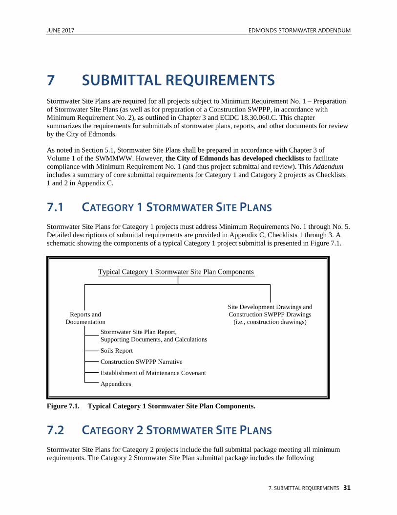
JUNE 2017 EDMONDS STORMWATER ADDENDUM
7. SUBMITTAL REQUIREMENTS 31
7 SUBMITTAL REQUIREMENTS Stormwater Site Plans are required for all projects subject to Minimum Requirement No. 1 – Preparation of Stormwater Site Plans (as well as for preparation of a Construction SWPPP, in accordance with Minimum Requirement No. 2), as outlined in Chapter 3 and ECDC 18.30.060.C. This chapter summarizes the requirements for submittals of stormwater plans, reports, and other documents for review by the City of Edmonds.
As noted in Section 5.1, Stormwater Site Plans shall be prepared in accordance with Chapter 3 of Volume 1 of the SWMMWW. However, the City of Edmonds has developed checklists to facilitate compliance with Minimum Requirement No. 1 (and thus project submittal and review). This Addendum includes a summary of core submittal requirements for Category 1 and Category 2 projects as Checklists 1 and 2 in Appendix C.
7.1 CATEGORY 1 STORMWATER SITE PLANS Stormwater Site Plans for Category 1 projects must address Minimum Requirements No. 1 through No. 5. Detailed descriptions of submittal requirements are provided in Appendix C, Checklists 1 through 3. A schematic showing the components of a typical Category 1 project submittal is presented in Figure 7.1.
Figure 7.1. Typical Category 1 Stormwater Site Plan Components.
7.2 CATEGORY 2 STORMWATER SITE PLANS Stormwater Site Plans for Category 2 projects include the full submittal package meeting all minimum requirements. The Category 2 Stormwater Site Plan submittal package includes the following
Typical Category 1 Stormwater Site Plan Components
Site Development Drawings and Construction SWPPP Drawings
(i.e., construction drawings) Stormwater Site Plan Report, Supporting Documents, and Calculations
Soils Report
Construction SWPPP Narrative
Establishment of Maintenance Covenant
Appendices
Reports and Documentation
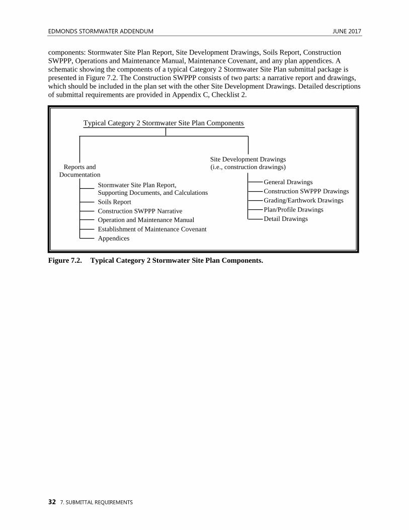
EDMONDS STORMWATER ADDENDUM JUNE 2017
32 7. SUBMITTAL REQUIREMENTS
components: Stormwater Site Plan Report, Site Development Drawings, Soils Report, Construction SWPPP, Operations and Maintenance Manual, Maintenance Covenant, and any plan appendices. A schematic showing the components of a typical Category 2 Stormwater Site Plan submittal package is presented in Figure 7.2. The Construction SWPPP consists of two parts: a narrative report and drawings, which should be included in the plan set with the other Site Development Drawings. Detailed descriptions of submittal requirements are provided in Appendix C, Checklist 2.
Figure 7.2. Typical Category 2 Stormwater Site Plan Components.
Site Development Drawings (i.e., construction drawings)
Construction SWPPP Drawings
Plan/Profile Drawings
General Drawings
Grading/Earthwork Drawings
Detail Drawings
Stormwater Site Plan Report, Supporting Documents, and Calculations Soils Report Construction SWPPP Narrative
Establishment of Maintenance Covenant Appendices
Operation and Maintenance Manual
Typical Category 2 Stormwater Site Plan Components
Reports and Documentation