addendum to cae fidelis™ lucina u uide content · user guide addendum - may 2016 905k471652 v2.3...
TRANSCRIPT

User Guide Addendum - May 2016
905K471652 v2.3 1
ADDENDUM TO CAE FIDELIS™ LUCINA USER GUIDE CONTENTPlease refer to the updated information in this addendum when utilizing these features on the Lucina simulator:
• Blood Tank and Boggy/Contracted Uterus baffle port connection instructions for 5-port top, refer to instructions beginning on Page 2 .
º Installing the Blood Tank
º Installing the Boggy/Contracted Uterus with bag
º Cleaning the Bleeding System
• Blood Tank and Boggy/Contracted Uterus baffle port connection instructions for 3-port top, refer to instructions beginning on Page 12.
º Installing the Blood Tank
º Installing the Boggy/Contracted Uterus with bag
º Cleaning the Bleeding System
• Mannequin Setup for Cesarean Breech SCE.
• Mannequin Setup for Cesarean Vertex SCE.
• Fetal and Labor Basic Parameters includes Late Deceleration Amplification Factor.
• Patient Baseline Parameters Operating Mode includes Non-Gravid mode (Non-pregnant patient).

User Guide Addendum - May 2016
2
For mannequin baffles with 5-port top connections, follow these instructions:
The Baffle with 5-Port Top Connection
Installing the Blood Tank
The Blood Tank
To install the blood tank:
1. Ensure the rotation ring is removed from inside the mannequin’s torso.
CAUTION: Do not place pressure or any object on the rotation ring support arms while the rotation ring is removed.
The Mannequin’s Torso - Rotation Ring Removed
The Tank Enable tube
The Blood Intube
User Guide Addendum - May 2016
905K471652 v2.3 3
2. Ensure no other birth canal is installed within the standard delivery birth canal. The standard birth canal is installed by default.
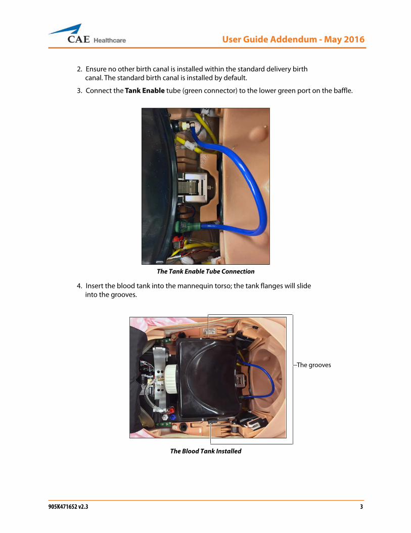
3. Connect the Tank Enable tube (green connector) to the lower green port on the baffle.
The Tank Enable Tube Connection
4. Insert the blood tank into the mannequin torso; the tank flanges will slide into the grooves.
The Blood Tank Installed
The grooves
User Guide Addendum - May 2016
4
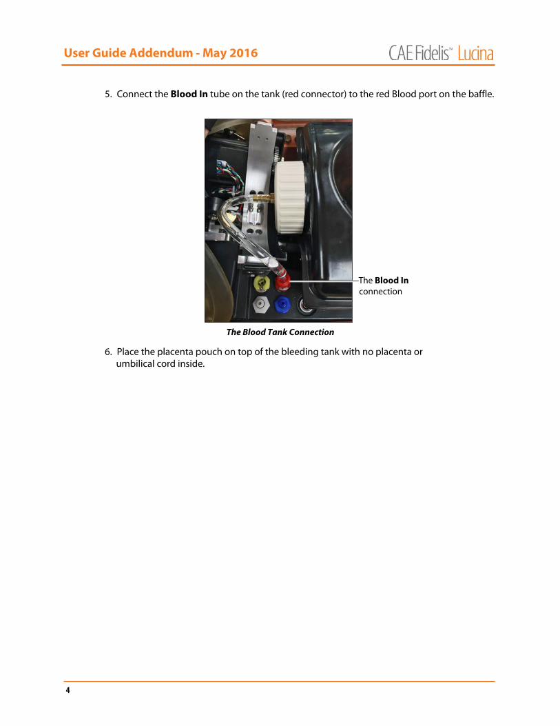
5. Connect the Blood In tube on the tank (red connector) to the red Blood port on the baffle.
The Blood Tank Connection
6. Place the placenta pouch on top of the bleeding tank with no placenta or umbilical cord inside.
The Blood In connection

User Guide Addendum - May 2016
905K471652 v2.3 5
Installing the Boggy/Contracted UterusIMPORTANT: Ensure the blood tank is installed with the use of the postpartum boggy/contracted uterus, whether or not the bleeding function is used. The postpartum boggy/contracted uterus is placed inside the abdominal cavity over the blood tank.
NOTE: The uterus bag should be installed and used with the boggy/postpartum uterus at all times.
The uterus has two connections:
• An air connection to inflate the uterus and create the perception of a boggy uterus (Uterus Air tube).
• A blood connection to support vaginal bleeding (Blood Uterus tube).
IMPORTANT: Follow these configuration instructions carefully to ensure that no fluid infiltrates the electrical area inside the mannequin and damages the simulator.
The Boggy/Contracted Uterus
To install the boggy/contracted uterus:
1. Ensure the rotation ring is removed from the mannequin’s torso.
2. Ensure the blood tank is installed.
3. Ensure the placenta pouch is placed on top of the blood tank.
The Blood Uterus tube
The Uterus Air tube

User Guide Addendum - May 2016
6
4. Connect the Blood Uterus tube (red connector) to the red Blood Out port on the lower baffle.
The Lower Baffle Ports
For proper placement, ensure the Uterus Air tube (blue connector) is positioned above the Blood Uterus tube (red connector).
5. Place the boggy/contracted uterus in the abdominal cavity over the placenta pouch. Ensure the bag is pulled snug with any slack tucked under the uterus.
The Boggy/Contracted Uterus Installed
The Blood Out port

User Guide Addendum - May 2016
905K471652 v2.3 7
6. Connect the Uterus Air tube (blue connector) to the blue Contract port on the baffle.
The Baffle Ports
NOTE: The orange valve on the blue uterus tube does not have a connection site. The valve remains open to release air during contraction. Ensure the two arrows on the orange valve remain aligned together.
7. Lightly lubricate the birth canal and the mannequin’s external genitalia using the cottonseed oil provided.
8. Lubricate the boggy/contracted uterus external genitalia.
9. Gather the boggy/contracted uterus external genitalia fully inside the mannequin’s torso and push the skin through the birth canal.
The Boggy/Contracted Uterus with External Genitalia
The blue Contract port
The external genitalia
User Guide Addendum - May 2016
8
10. Tuck in the labia and position the uterus genitalia smoothly over the standard birth canal.
11. Tuck the edge skin of the uterus under the torso skin around the genitalia opening.
12. Push the external genitalia flap under the buttocks and attach it to the rectal plug.
NOTE: CAE Healthcare recommends placing the mannequin in McRoberts position to perform this procedure.
13. Install the Backplate without the Cervix Retention Plate.
NOTE: Ensure the arrows on the top of the plate point towards the mannequin’s feet.

User Guide Addendum - May 2016
905K471652 v2.3 9
Cleaning the Bleeding SystemThe bleeding system needs to be cleaned with distilled water after simulated blood has been used.
Once a month, flush the system with a 50/50 mix of distilled water and white vinegar to keep mineral and algae build up to a minimum. Always flush with distilled water to remove any trace amounts of vinegar.
NOTE: The mannequin should be configured for a postpartum SCE prior to cleaning the bleeding system, with the blood tank and boggy/contracted (postpartum) uterus installed.
1. Make sure the tank has been drained of any simulated blood.
2. Rinse thoroughly the trauma fill tank of any simulated blood.
3. Fill with distilled water or the 50/50 mixture of distilled water and white vinegar.
4. Connect the trauma fill tank to the mannequin. The blue tube connects to the BLOOD FILL port and yellow tube connects to the BLOOD VENT port.
5. Pressurize the trauma fill tank using the hand pump. Wait until there is reflow in the reclaim bottle.
6. Place absorbent pads under the buttocks and the vaginal opening.
7. From the Instructor Workstation, click on the System Administration icon in the upper-right corner of the Müse home screen.
The System Administration Button
The System Administration screen appears.
8. Click on the Maintenance tab.
The Maintenance Panel
The Maintenance panel appears.
9. Click the Flush System button.
The Maintenancepanel
The Flush System button
The Maintenancetab
User Guide Addendum - May 2016
10
The Flush in progress window appears.
10. Run until the fluids run clear from the simulator and click the Finished button.
11. Disconnect the trauma fill tank from the mannequin and depressurize.
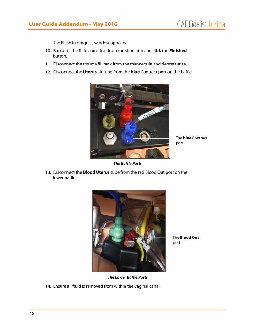
12. Disconnect the Uterus air tube from the blue Contract port on the baffle
The Baffle Ports
13. Disconnect the Blood Uterus tube from the red Blood Out port on the lower baffle
The Lower Baffle Ports
14. Ensure all fluid is removed from within the vaginal canal.
The blue Contract port
The Blood Out port
User Guide Addendum - May 2016
905K471652 v2.3 11
15. Wipe the external area particularly the buttocks and under the skin surrounding the vaginal opening.
The food color will stain more readily if left on for an extended period.
16. Remove the uterus by folding the labia and perineum flaps closed together and pushing the external genitalia up through the birth canal into the mannequin’s torso.
17. Hold the labia and perineum closed and slowly lift the uterus out from inside the abdomen.
18. Ensure that no left over fluid spills inside the abdomen.
IMPORTANT: If any fluid gets inside the mannequin, follow these cleaning instructions immediately to prevent damage to the simulator:
a. Ensure the abdomen is installed on the torso whenever the mannequin is positioned upright.
b. Elevate the torso.
c. Lean the mannequin forward.
d. Unzip the torso skin zipper.
e. Open the skin on the back to expose the area under the buttocks.
f. Clean the area where fluid is located.
g. Reattach the skin and return the mannequin to supine position.
h. Clean any remaining liquid in the front of the vaginal opening.

User Guide Addendum - May 2016
12
For mannequin baffles with 3-port top connections, follow these instructions:
The Baffle with 3-Port Top Connection
Installing the Blood TankTo install the blood tank:
1. Ensure the rotation ring from inside the mannequin’s torso is removed.
CAUTION: Do not place pressure or any object on the rotation ring support arms while the rotation ring is removed.
The Mannequin’s Torso - Rotation Ring Removed
2. Ensure no other birth canal is installed within the standard delivery birth canal.
NOTE: The standard birth canal is installed by default.

User Guide Addendum - May 2016
905K471652 v2.3 13
3. Connect the clear blue tube located at the bottom of the blood tank to the BLEEDING tube inside the mannequin.
The BLEEDING Tube Connection
NOTE: The BLEEDING tube is a clear blue tube located on the left side of the mannequin’s torso.
4. Connect the blood tank outlet (clear tube located at the top of the blood tank) to the mannequin BLOOD port on the baffle.
The Blood Tank Outlet and Blood Port
5. Place the blood tank inside the mannequin’s torso.
6. Place the placenta pouch on top of the bleeding tank with no placenta or umbilical cord inside.
The clear blue tubeThe BLEEDING
tube
The bloodtank outlet
The BLOODport

User Guide Addendum - May 2016
14
Installing the Boggy/Contracted Uterus With BagIMPORTANT: Ensure the blood tank is installed with the use of the postpartum boggy/contracted uterus, whether or not the bleeding function is used. The postpartum boggy/contracted uterus with bag is placed inside the abdominal cavity over the blood tank.
NOTE: The uterus bag should be installed and used with the boggy/postpartum uterus at all times.
The uterus has two connections:
• A pneumatic connection to inflate the uterus and create the perception of a boggy uterus.
• A bleed connection to support vaginal bleeding.
IMPORTANT: Follow these configuration instructions carefully to ensure that no fluid infiltrates the electrical area inside the mannequin and damages the simulator.
To install the boggy/contracted uterus:
1. Ensure the rotation ring is removed from the mannequin’s torso.
2. Ensure the blood tank is installed.
3. Ensure the placenta pouch is placed on top of the blood tank.
4. Thread the cable tie completely through the bag opening.
NOTE: The cable tie may also be threaded through the bag after installing the bag on the uterus.
The Boggy/Contracted Uterus Bag
The cable tie
User Guide Addendum - May 2016
905K471652 v2.3 15
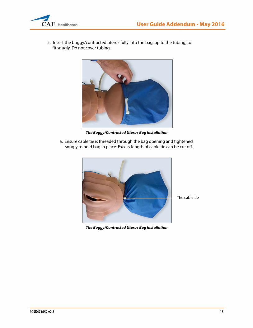
5. Insert the boggy/contracted uterus fully into the bag, up to the tubing, to fit snugly. Do not cover tubing.
The Boggy/Contracted Uterus Bag Installation
a. Ensure cable tie is threaded through the bag opening and tightened snugly to hold bag in place. Excess length of cable tie can be cut off.
The Boggy/Contracted Uterus Bag Installation
The cable tie
User Guide Addendum - May 2016
16
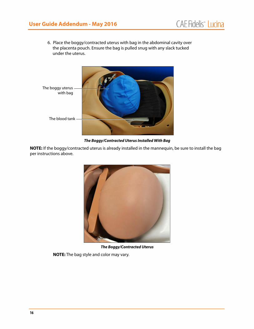
6. Place the boggy/contracted uterus with bag in the abdominal cavity over the placenta pouch. Ensure the bag is pulled snug with any slack tucked under the uterus.
The Boggy/Contracted Uterus Installed With Bag
NOTE: If the boggy/contracted uterus is already installed in the mannequin, be sure to install the bag per instructions above.
The Boggy/Contracted Uterus
NOTE: The bag style and color may vary.
The blood tank
The boggy uteruswith bag
User Guide Addendum - May 2016
905K471652 v2.3 17
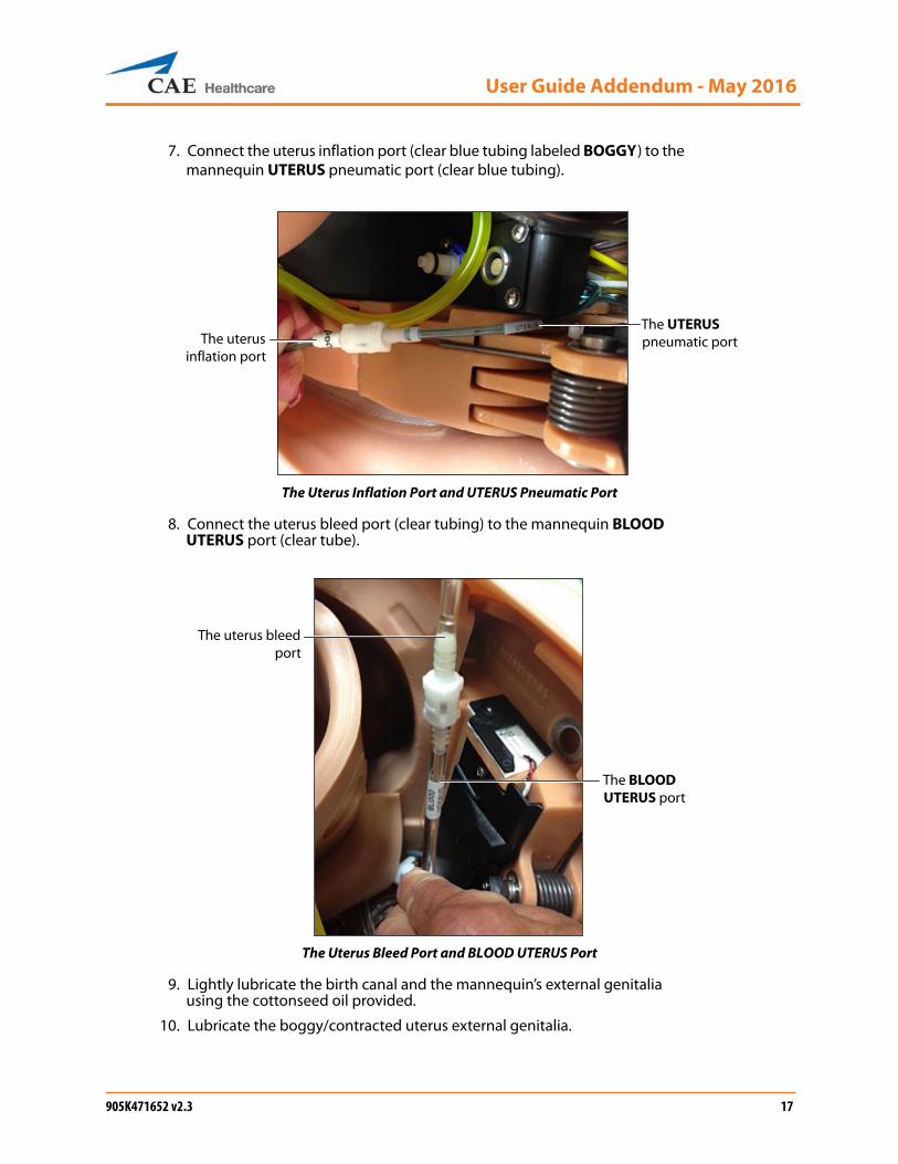
7. Connect the uterus inflation port (clear blue tubing labeled BOGGY) to the mannequin UTERUS pneumatic port (clear blue tubing).
The Uterus Inflation Port and UTERUS Pneumatic Port
8. Connect the uterus bleed port (clear tubing) to the mannequin BLOOD UTERUS port (clear tube).
The Uterus Bleed Port and BLOOD UTERUS Port
9. Lightly lubricate the birth canal and the mannequin’s external genitalia using the cottonseed oil provided.
10. Lubricate the boggy/contracted uterus external genitalia.
The uterusinflation port
The UTERUS pneumatic port
The uterus bleedport
The BLOOD UTERUS port

User Guide Addendum - May 2016
18
11. Gather the boggy/contracted uterus external genitalia fully inside the mannequin’s torso and push the skin through the birth canal.
The Boggy/Contracted Uterus with External Genitalia
12. Tuck in the labia and position the uterus genitalia smoothly over the standard birth canal.
13. Tuck the edge skin of the uterus under the torso skin around the genitalia opening.
14. Push the external genitalia flap under the buttocks and attach it to the rectal plug.
NOTE: CAE Healthcare recommends placing the mannequin in McRoberts position to perform this procedure.
15. Install the Backplate without the Cervix Retention Plate.
NOTE: Ensure the arrows on the top of the plate point towards the mannequin’s feet.
The external genitalia
User Guide Addendum - May 2016
905K471652 v2.3 19
Cleaning the Bleeding SystemThe bleeding system needs to be cleaned with distilled water after simulated blood has been used.
Once a month, flush the system with a 50/50 mix of distilled water and white vinegar to keep mineral and algae build up to a minimum. Always flush with distilled water to remove any trace amounts of vinegar.
NOTE: The mannequin should be configured for a postpartum SCE prior to cleaning the bleeding system, with the blood tank and boggy/contracted (postpartum) uterus installed.
1. Make sure the tank has been drained of any simulated blood.
2. Rinse thoroughly the trauma fill tank of any simulated blood.
3. Fill with distilled water or the 50/50 mixture of distilled water and white vinegar.
4. Connect the trauma fill tank to the mannequin. The blue tube connects to the BLOOD FILL port and yellow tube connects to the BLOOD VENT port.
5. Pressurize the trauma fill tank using the hand pump. Wait until there is reflow in the reclaim bottle.
6. Place absorbent pads under the buttocks and the vaginal opening.
7. From the Instructor Workstation, click on the System Administration icon in the upper-right corner of the Müse home screen.
The System Administration Button
The System Administration screen appears.
8. Click on the Maintenance tab.
The Maintenance Panel
The Maintenance panel appears.
The Maintenancepanel
The Flush System button
The Maintenancetab

User Guide Addendum - May 2016
20
9. Click the Flush System button.
The Flush in progress window appears.
10. Run until the fluids run clear from the simulator and click the Finished button.
11. Disconnect the trauma fill tank from the mannequin and depressurize.
12. Disconnect the UTERUS pneumatic port from the uterus inflation port
The Uterus Inflation Port and UTERUS Pneumatic Port
13. Disconnect the BLOOD UTERUS port from the uterus bleed port.
The Uterus Bleed Port and BLOOD UTERUS Port
14. Ensure all fluid is removed from within the vaginal canal.
The uterusinflation port
The UTERUS pneumatic port
The uterusbleed port
The BLOOD UTERUS port

User Guide Addendum - May 2016
905K471652 v2.3 21
15. Wipe the external area particularly the buttocks and under the skin surrounding the vaginal opening.
The food color will stain more readily if left on for an extended period.
16. Remove the uterus by folding the labia and perineum flaps closed together and pushing the external genitalia up through the birth canal into the mannequin’s torso.
17. Hold the labia and perineum closed and slowly lift the uterus out from inside the abdomen.
18. Ensure that no left over fluid spills inside the abdomen.
IMPORTANT: If any fluid gets inside the mannequin, follow these cleaning instructions immediately to prevent damage to the simulator:
a. Ensure the abdomen is installed on the torso whenever the mannequin is positioned upright.
b. Elevate the torso.
c. Lean the mannequin forward.
d. Unzip the torso skin zipper.
e. Open the skin on the back to expose the area under the buttocks.
f. Clean the area where fluid is located.
g. Reattach the skin and return the mannequin to supine position.
h. Clean any remaining liquid in the front of the vaginal opening.
User Guide Addendum - May 2016
22
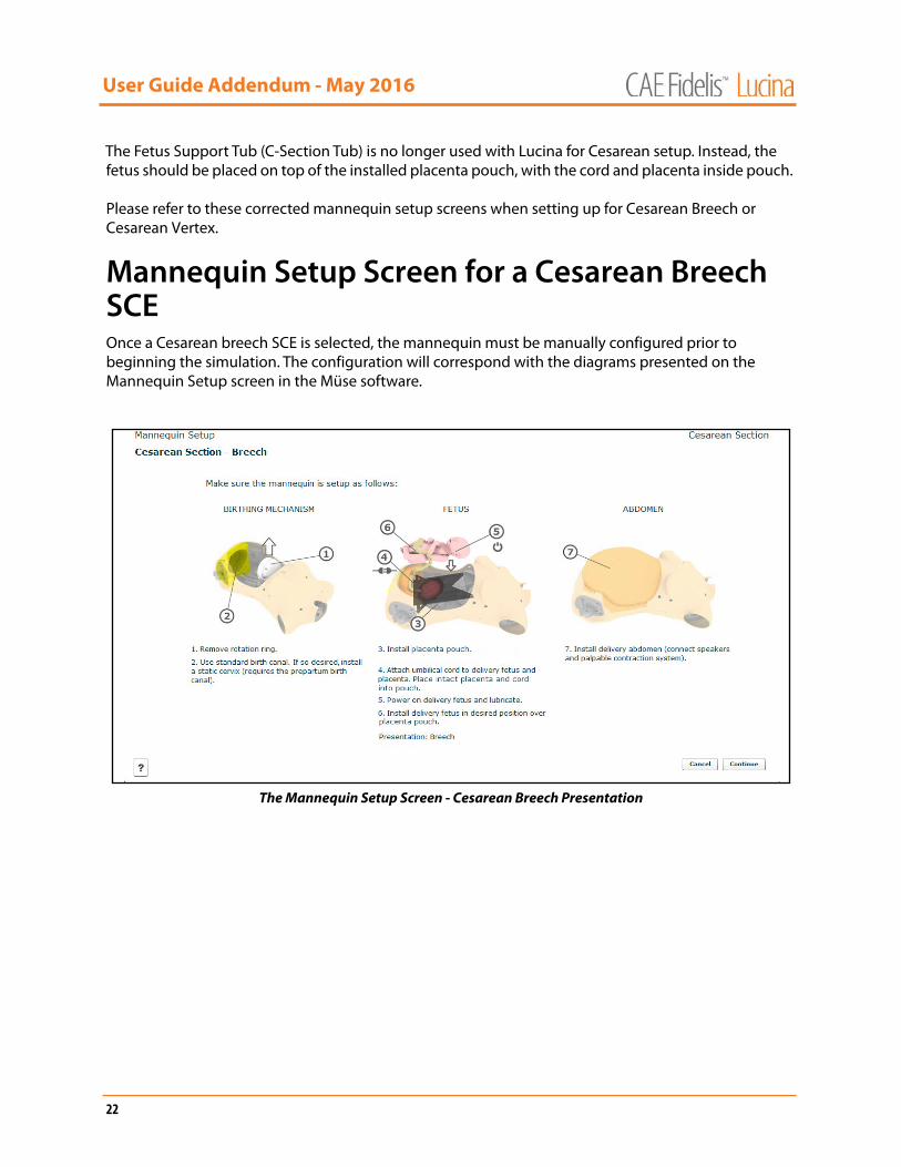
The Fetus Support Tub (C-Section Tub) is no longer used with Lucina for Cesarean setup. Instead, the fetus should be placed on top of the installed placenta pouch, with the cord and placenta inside pouch.
Please refer to these corrected mannequin setup screens when setting up for Cesarean Breech or Cesarean Vertex.
Mannequin Setup Screen for a Cesarean Breech SCEOnce a Cesarean breech SCE is selected, the mannequin must be manually configured prior to beginning the simulation. The configuration will correspond with the diagrams presented on the Mannequin Setup screen in the Müse software.
The Mannequin Setup Screen - Cesarean Breech Presentation

User Guide Addendum - May 2016
905K471652 v2.3 23
Mannequin Setup Screen for a Cesarean Vertex SCEOnce a Cesarean vertex SCE is selected, the mannequin must be manually configured prior to beginning the simulation. The configuration will correspond with the diagrams presented on the Mannequin Setup screen in the Müse software.
The Mannequin Setup Screen - Cesarean Vertex Presentation

User Guide Addendum - May 2016
24
Fetal and Labor Basic Parameters includes Late Deceleration Amplification Factor.
Fetal and Labor - Basic Parameters
Late Deceleration Amplification FactorFetal heart rate (FHR) late decelerations associated with uterine contractions (UCs) are attributed to reductions in oxygen supply from the mother. The Late Deceleration Amplification Factor parameter allows for greater control over the amplitude of late decelerations in conditions where they would be expected, notably for the fetal patient with placental insufficiency. In addition, use of this parameter allows the instructor to demonstrate late decelerations for the normal fetus in the cases of maternal hypotension and uterine hyperactivity.
The Late Deceleration Amplification Factor is a multiplicative factor applied to the oxygen distribution in the fetus. Values above 1.0 speed up the propagation of reduced oxygen levels from the placenta to the fetal arteries.
Default: 1.0
Range: 1.0 – 5.0
Fetal and Labor Parameters - Basic
Rate of Descent
Fetal State
Contraction Frequency
Contraction Amplitude
Contraction Duration
Patient Pushing
Early Deceleration Magnitude
Late Deceleration Amplification Factor
Shoulder Dystocia
Shoulder Dystocia Resolution
Extraction of Posterior Arm
Arrested Labor
Arrested Labor Trigger Station
Arrested Labor Resolved by Traction
Traction Force Required to Resolve Arrested Labor
Manual Release of the Baby

User Guide Addendum - May 2016
905K471652 v2.3 25
Patient Baseline Parameters Operating Mode includes Non-Gravid mode (Non-pregnant patient).
Patient Baseline - Parameters
Operating ModeThe Operating Mode parameter determines the overall hardware configuration and mode of operation for the mannequin. Operating modes are mutually exclusive and govern the mannequin hardware configuration and operation for the complete execution of a given SCE. Migration from one operating mode to another always entails a physical reconfiguration of the simulator. Reconfiguration occurs only at the start of the SCE except for Postpartum operating mode that can be combined with a vaginal delivery.
Possible modes include:
Prepartum & Latent Phase – Non-delivery operating mode that calls for a hardware configuration that allows performance of Leopold maneuver and assessment of static cervices.
Active Phase – Non-delivery operating mode that calls for a hardware configuration that uses the dynamic cervix to allow access and/or visibility to the fetus. Intended to emulate such conditions as cord prolapse or placenta abruption.
Vaginal Delivery – Delivery operating mode that supports spontaneous realistic delivery of the fetus.
Patient Baseline Parameters
Operating Mode
Delivery Paused on Run
Postpartum Included
Cervix
Presentation
Initial Station
Vertex Rotation Type
Breech Initial Position
Cord Prolapse
Nuchal Cord
Placenta Condition
Postpartum Initial Uterine State
User Guide Addendum - May 2016
26
Cesarean Section – Non-delivery operating mode that allows the trainee to go through the motions of a cesarean section in order to support cesarean teamwork training.
Postpartum – Non-delivery operating mode that supports the management of the postpartum uterus.
Non-Gravid – Non–delivery operating mode that supports the management of a non-pregnant patient.
Default: Vaginal Delivery
The current User Guide can be found on the CAE Healthcare website www.caehealthcare.com under Support> User Guides.