addendum no. 1 - baltimore · addendum no. 1 march 28, ... k-series steel joist substitutes. ......
TRANSCRIPT

ADDENDUM No. 1 March 28, 2016
Little Sisters of the Poor Main Street Renovations 601 Maiden Choice Lane, Baltimore MD 21228
Project No: 15046.00
ARCHITECT:
Gaudreau, Inc. 810 Light Street Baltimore, Maryland 21230 410.837.5040
This Addendum forms part of the Contract Documents and modifies the original Bidding Documents dated March 4, 2016. Acknowledge receipt of this addendum in the space provided on the Bid Form. Failure to do so may subject Bidder to disqualification.
CHANGES TO SPECIFICATIONS:
1. Section 051200 Structural Steel: a. Article 1.7: The AISC Certification requirements are being waived for both the Fabricator and
Installer for this project.
2. See attached new Specification sections 052100 Steel Joists and 053100 Steel Decking.
3. Section 084113 Aluminum Framed Entrances and Storefronts: a. Article 2.5 Entrance Door Hardware. In addition to the hardware listed, provide the following:
Single doors: 1- Ives 8190-0 HD offset Door Pull, US32D finish; 1- Exit Device 35A-EO, 626 by Von Duprin; Concealed closer 2030 689 by LCN; Security floor stop FS18L BLK by Ives.
Double doors: 2- Ives 8190-0 HD offset Door Pull, US32D finish; 2 Exit Devices 35A-EO, 626 by Von Duprin; 2-Concealed closers 2030 689 by LCN; 2-Security floor stops FS18L BLK by Ives.
b. Operable window panels shall be outward tilt, Glassvent by Kawneer or equal, with insect screens and Cam handles.
4. Section 088000 Glazing: a. Revise Article 3.9 Insulating-Glass Types as follows:
A. Glass Type 1; All windows on Building West & South elevations. B. Glass Type 2; Glass doors on West & South elevations. C. Glass Type 3; All windows on Building East and North elevations.
5. Section 142400 Hydraulic Elevators:
a. Add paragraph 2.3 C as follows: C. Existing Elevator #1
1. Replace elevator cab finishes in their entirety including new elevator panels, new ceiling, lighting, hand rails and flooring (refer to finish schedule)
2. Replace elevator hall light and call buttons (both levels)
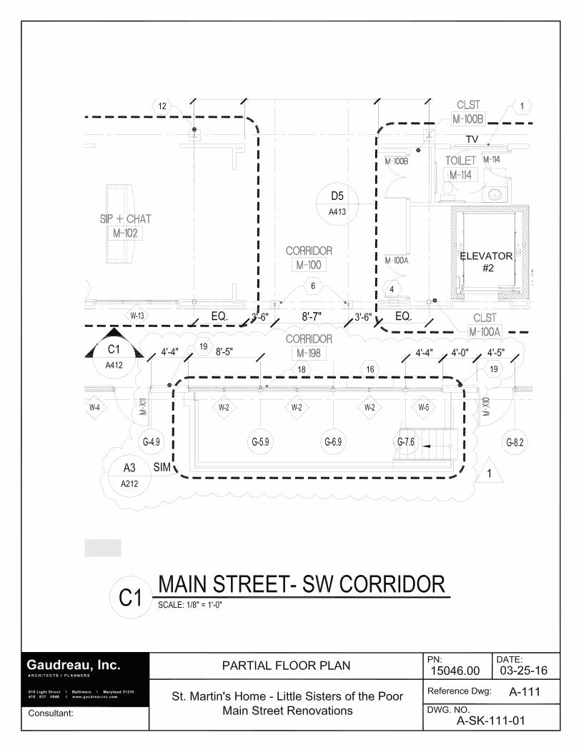
CHANGES TO DRAWINGS:
1. Drawing A-111: see attached sketches: a. Add new drawing note 19 as follows: “NEW EXTERIOR WALL, SEE B2/A-512 FOR DETAIL” b. A-SK-411-01: Door to Personal Care M-108 was revised; new exterior wall was clarified (note 19).

Little Sisters of the Poor Main Street Renovations Addendum No. 1 03/28/2016
2
c. A-SK-411-02: Enlarged detail A3/ A212 (sim) was referenced; dimensions were added and new Door to Personal Care M-108 was revised; new exterior wall was clarified (note 19).
d. Clarification for Note 18, new handrail: locate new handrail at new exterior storefront, typ except where they would conflict with the new fan coil units.
e. A-SK-411-03: See attached sketch for clarification of the casework elevations for the island in Games/ Hobby.
2. Drawing A-112: a. Clarification for Note 3, new handrail: locate new handrail at new exterior storefront, typical except
where a handrail would conflict with the new fan coil units. b. Corridor M-195: move the new fan coil unit from the north wall (outside the existing stair) to the
south wall, to the right of the entrance to Cottage C.
3. Drawing A114: a. Roof Plan A1: revise drawing scale to 1/8”=1’-0”.
4. Drawing A211:
a. Clarification: the number of operable vents in the storefront is (74), as indicated on the exterior elevations.
5. Drawing A-413; a. Toilet accessories Schedule: revise TA5 to Model #669 or equal; and TA5A to Model #6944 or
equal.
6. Drawing A613: a. Exterior Window Schedule: Refer to A211 for clarification of operable vent locations in the
storefront. The exterior elevations supersede the locations and quantities shown in the window schedule.
Attachments:
1. (2) New specification sections, 052100 Steel Joists and 053100 Steel Decking
2. (3) sketches as follows:
A-SK-111-01, 02 & 03;
END OF ADDENDUM No. 1

Gaudreau, Inc. Renovations to St. Martin’s Home Baltimore, MD Little Sisters of the Poor Project No. 15046.00 Baltimore, MD March 24, 2016
STEEL JOIST FRAMING 052100 - 1
SECTION 052100 - STEEL JOIST FRAMING
PART 1 - GENERAL
1.1 RELATED DOCUMENTS
A. Drawings and general provisions of the Contract, including General and Supplementary Conditions and Division 01 Specification Sections, apply to this Section.
1.2 SUMMARY
A. Section Includes:
1. K-series steel joists. 2. K-series steel joist substitutes. 3. Joist accessories.
B. Related Requirements:
1. Section 042000 "Unit Masonry" for installing bearing plates in unit masonry.
1.3 DEFINITIONS
A. SJI's "Specifications": Steel Joist Institute's "Standard Specifications, Load Tables and Weight Tables for Steel Joists and Joist Girders."
B. Special Joists: Steel joists or joist girders requiring modification by manufacturer to support nonuniform, unequal, or special loading conditions that invalidate load tables in SJI's "Specifications."
1.4 ACTION SUBMITTALS
A. Product Data: For each type of joist, accessory, and product.
B. Shop Drawings:
1. Include layout, designation, number, type, location, and spacing of joists. 2. Include joining and anchorage details, bracing, bridging, and joist accessories;
splice and connection locations and details; and attachments to other construction.
3. Indicate locations and details of bearing plates to be embedded in other construction.
Gaudreau, Inc. Renovations to St. Martin’s Home Baltimore, MD Little Sisters of the Poor Project No. 15046.00 Baltimore, MD March 24, 2016
STEEL JOIST FRAMING 052100 - 2
1.5 INFORMATIONAL SUBMITTALS
A. Welding certificates.
B. Manufacturer certificates.
C. Mill Certificates: For each type of bolt.
1.6 QUALITY ASSURANCE
A. Manufacturer Qualifications: A manufacturer certified by SJI to manufacture joists complying with applicable standard specifications and load tables in SJI's "Specifications”.
1. Manufacturer's responsibilities include providing professional engineering services for designing special joists to comply with performance requirements.
B. Welding Qualifications: Qualify field-welding procedures and personnel according to AWS D1.1/D1.1M, "Structural Welding Code - Steel."
1.7 DELIVERY, STORAGE, AND HANDLING
A. Deliver, store, and handle joists as recommended in SJI's "Specifications”.
B. Protect joists from corrosion, deformation, and other damage during delivery, storage, and handling.
1.8 SEQUENCING
A. Deliver steel bearing plates to be built into masonry construction.
PART 2 - PRODUCTS
2.1 PERFORMANCE REQUIREMENTS
A. Structural Performance: Provide special joists and connections capable of withstanding design loads indicated.
1. Use ASD; data are given at service-load level. 2. Design special joists to withstand design loads with live-load deflections no
greater than the following:
a. Floor Joists: Vertical deflection of 1/360 of the span. b. Roof Joists: Vertical deflection of 1/240 of the span.

Gaudreau, Inc. Renovations to St. Martin’s Home Baltimore, MD Little Sisters of the Poor Project No. 15046.00 Baltimore, MD March 24, 2016
STEEL JOIST FRAMING 052100 - 3
2.2 K-SERIES STEEL JOISTS
A. Manufacture steel joists of type indicated according to "Standard Specifications for Open Web Steel Joists, K-Series" in SJI's "Specifications," with steel-angle top- and bottom-chord members, underslung ends, and parallel top chord.
1. Joist Type: K-series steel joists.
B. Steel Joist Substitutes: Manufacture according to "Standard Specifications for Open Web Steel Joists, K-Series" in SJI's "Specifications," with steel-angle or -channel members.
C. Provide holes in chord members for connecting and securing other construction to joists.
D. Top-Chord Extensions: Extend top chords of joists with SJI's Type S top-chord extensions where indicated, complying with SJI's "Specifications."
E. Extended Ends: Extend bearing ends of joists with SJI's Type R extended ends where indicated, complying with SJI's "Specifications."
F. Do not camber joists.
G. Equip bearing ends of joists with manufacturer's standard beveled ends or sloped shoes if joist slope exceeds 1/4 inch per 12 inches (1:48).
2.3 PRIMERS
A. Low-Emitting Materials: Paints and coatings shall comply with the testing and product requirements of the California Department of Health Services' "Standard Practice for the Testing of Volatile Organic Emissions from Various Sources Using Small-Scale Environmental Chambers."
B. Primer: SSPC-Paint 15, or manufacturer's standard shop primer complying with performance requirements in SSPC-Paint 15.
2.4 JOIST ACCESSORIES
A. Bridging: Provide bridging anchors and number of rows of horizontal or diagonal bridging of material, size, and type required by SJI's "Specifications” for type of joist, chord size, spacing, and span. Furnish additional erection bridging if required for stability.
B. Bridging: Schematically indicated. Detail and fabricate according to SJI's "Specifications”. Furnish additional erection bridging if required for stability.

Gaudreau, Inc. Renovations to St. Martin’s Home Baltimore, MD Little Sisters of the Poor Project No. 15046.00 Baltimore, MD March 24, 2016
STEEL JOIST FRAMING 052100 - 4
C. Bridging: Fabricate as indicated and according to SJI's "Specifications”. Furnish additional erection bridging if required for stability.
D. Fabricate steel bearing plates from ASTM A 36/A 36M steel with integral anchorages of sizes and thicknesses indicated. Hot-dip zinc coat according to ASTM A 123/A 123M.
E. Steel bearing plates with integral anchorages are specified in Section 055000 "Metal Fabrications."
F. Furnish ceiling extensions, either extended bottom-chord elements or a separate extension unit of enough strength to support ceiling construction. Extend ends to within 1/2 inch (13 mm) of finished wall surface unless otherwise indicated.
G. High-Strength Bolts, Nuts, and Washers: ASTM A 325 (ASTM A 325M), Type 1, heavy hex steel structural bolts; ASTM A 563 (ASTM A 563M) heavy hex carbon-steel nuts; and ASTM F 436 (ASTM F 436M) hardened carbon-steel washers.
1. Finish: Plain
H. Welding Electrodes: Comply with AWS standards.
I. Furnish miscellaneous accessories including splice plates and bolts required by joist manufacturer to complete joist assembly.
2.5 CLEANING AND SHOP PAINTING
A. Clean and remove loose scale, heavy rust, and other foreign materials from fabricated joists and accessories by hand-tool cleaning, SSPC-SP 2 or power-tool cleaning, SSPC-SP 3.
B. Do not prime paint joists and accessories to receive sprayed fire-resistive materials.
C. Apply one coat of shop primer to joists and joist accessories to be primed to provide a continuous, dry paint film not less than 1 mil (0.025 mm) thick.
D. Shop priming of joists and joist accessories is specified in Section 099113 "Exterior Painting" and Section 099123 "Interior Painting."
PART 3 - EXECUTION
3.1 EXAMINATION
A. Examine supporting substrates, embedded bearing plates, and abutting structural framing for compliance with requirements for installation tolerances and other conditions affecting performance.
Gaudreau, Inc. Renovations to St. Martin’s Home Baltimore, MD Little Sisters of the Poor Project No. 15046.00 Baltimore, MD March 24, 2016
STEEL JOIST FRAMING 052100 - 5
B. Proceed with installation only after unsatisfactory conditions have been corrected.
3.2 INSTALLATION
A. Do not install joists until supporting construction is in place and secured.
B. Install joists and accessories plumb, square, and true to line; securely fasten to supporting construction according to SJI's "Specifications”, joist manufacturer's written recommendations, and requirements in this Section.
1. Before installation, splice joists delivered to Project site in more than one piece. 2. Space, adjust, and align joists accurately in location before permanently
fastening. 3. Install temporary bracing and erection bridging, connections, and anchors to
ensure that joists are stabilized during construction. 4. Delay rigidly connecting bottom-chord extensions to columns or supports until
dead loads are applied.
C. Field weld joists to supporting steel bearing plates and framework. Coordinate welding sequence and procedure with placement of joists. Comply with AWS requirements and procedures for welding, appearance and quality of welds, and methods used in correcting welding work.
D. Bolt joists to supporting steel framework using carbon-steel bolts.
E. Bolt joists to supporting steel framework using high-strength structural bolts. Comply with Research Council on Structural Connection's "Specification for Structural Joints Using ASTM A 325 or ASTM A 490 Bolts" for high-strength structural bolt installation and tightening requirements.
F. Install and connect bridging concurrently with joist erection, before construction loads are applied. Anchor ends of bridging lines at top and bottom chords if terminating at walls or beams.
3.3 FIELD QUALITY CONTROL
A. Testing Agency: Owner will engage a qualified independent testing and inspecting agency to inspect field welds and bolted connections and to perform field tests and inspections and prepare test and inspection reports.
B. Visually inspect field welds according to AWS D1.1/D1.1M.
C. Visually inspect bolted connections.
D. Correct deficiencies in Work that test and inspection reports have indicated are not in compliance with specified requirements.

Gaudreau, Inc. Renovations to St. Martin’s Home Baltimore, MD Little Sisters of the Poor Project No. 15046.00 Baltimore, MD March 24, 2016
STEEL JOIST FRAMING 052100 - 6
E. Perform additional testing to determine compliance of corrected Work with specified requirements.
3.4 PROTECTION
A. Repair damaged galvanized coatings on galvanized items with galvanized repair paint according to ASTM A 780 and manufacturer's written instructions.
B. Touchup Painting: After installation, promptly clean, prepare, and prime or reprime field connections, rust spots, and abraded surfaces of prime-painted joists, bearing plates, abutting structural steel, and accessories.
1. Clean and prepare surfaces by hand-tool cleaning according to SSPC-SP 2, or power-tool cleaning according to SSPC-SP 3.
2. Apply a compatible primer of same type as primer used on adjacent surfaces.
C. Touchup Painting: Cleaning and touchup painting are specified in Section 099113 "Exterior Painting" and Section 099123 "Interior Painting."
D. Provide final protection and maintain conditions, in a manner acceptable to manufacturer and Installer, that ensure that joists and accessories are without damage or deterioration at time of Substantial Completion.
END OF SECTION 052100

Gaudreau, Inc. Renovations to St. Martin’s Home Baltimore, MD Little Sisters of the Poor Project No. 15046.00 Baltimore, MD March 24, 2016
STEEL DECKING 053100 - 1
SECTION 053100 - STEEL DECKING
PART 1 - GENERAL
1.1 RELATED DOCUMENTS
A. Drawings and general provisions of the Contract, including General and Supplementary Conditions and Division 01 Specification Sections, apply to this Section.
1.2 SUMMARY
A. Section Includes:
1. Roof deck. 2. Noncomposite form deck.
B. Related Requirements:
1. Section 033000 "Cast-in-Place Concrete" for normal-weight and lightweight structural concrete fill over steel deck.
2. Section 055000 "Metal Fabrications" for framing deck openings with miscellaneous steel shapes.
1.3 ACTION SUBMITTALS
A. Product Data: For each type of deck, accessory, and product indicated.
B. Shop Drawings:
1. Include layout and types of deck panels, anchorage details, reinforcing channels, pans, cut deck openings, special jointing, accessories, and attachments to other construction.
1.4 INFORMATIONAL SUBMITTALS
A. Welding certificates.
B. Product Certificates: For each type of steel deck.
1.5 QUALITY ASSURANCE
A. Testing Agency Qualifications: Qualified according to ASTM E 329 for testing indicated.
B. Welding Qualifications: Qualify procedures and personnel according to AWS D1.3, "Structural Welding Code - Sheet Steel."

Gaudreau, Inc. Renovations to St. Martin’s Home Baltimore, MD Little Sisters of the Poor Project No. 15046.00 Baltimore, MD March 24, 2016
STEEL DECKING 053100 - 2
C. FM Global Listing: Provide steel roof deck evaluated by FM Global and listed in its "Approval Guide, Building Materials" for Class 1 fire rating and Class 1-90 windstorm ratings.
1.6 DELIVERY, STORAGE, AND HANDLING
A. Protect steel deck from corrosion, deformation, and other damage during delivery, storage, and handling.
B. Stack steel deck on platforms or pallets and slope to provide drainage. Protect with a waterproof covering and ventilate to avoid condensation.
PART 2 - PRODUCTS
2.1 PERFORMANCE REQUIREMENTS
A. AISI Specifications: Comply with calculated structural characteristics of steel deck according to AISI's "North American Specification for the Design of Cold-Formed Steel Structural Members."
B. Fire-Resistance Ratings: Comply with ASTM E 119; testing by a qualified testing agency. Identify products with appropriate markings of applicable testing agency.
2.2 ROOF DECK
A. Manufacturers: Subject to compliance with requirements, available manufacturers offering products that may be incorporated into the Work include, but are not limited to, the following: 1. Canam United States; Canam Group Inc. 2. New Millennium Building Systems, LLC. 3. Nucor Corp.; Vulcraft Group. 4. Verco Manufacturing Co.
B. Roof Deck: Fabricate panels, without top-flange stiffening grooves, to comply with "SDI Specifications and Commentary for Steel Roof Deck," in SDI Publication No. 31, and with the following:
1. Galvanized-Steel Sheet: ASTM A 653/A 653M, Structural Steel (SS), Grade 33, G90 (Z275) zinc coating.
2. Deck Profile: As indicated. 3. Profile Depth: As indicated. 4. Design Uncoated-Steel Thickness: As indicated. 5. Design Uncoated-Steel Thicknesses; Deck Unit/Bottom Plate: As indicated. 6. Span Condition: Triple span or more. 7. Side Laps: Overlapped or interlocking seam at Contractor's option.
2.3 NONCOMPOSITE FORM DECK
A. Manufacturers: Subject to compliance with requirements, available manufacturers offering products that may be incorporated into the Work include, but are not limited to, the following:

Gaudreau, Inc. Renovations to St. Martin’s Home Baltimore, MD Little Sisters of the Poor Project No. 15046.00 Baltimore, MD March 24, 2016
STEEL DECKING 053100 - 3
1. Canam United States; Canam Group Inc. 2. New Millennium Building Systems, LLC. 3. Nucor Corp.; Vulcraft Group. 4. Verco Manufacturing Co.
B. Noncomposite Form Deck: Fabricate ribbed-steel sheet noncomposite form-deck panels to comply with "SDI Specifications and Commentary for Noncomposite Steel Form Deck," in SDI Publication No. 31, with the minimum section properties indicated, and with the following:
1. Galvanized-Steel Sheet: ASTM A 653/A 653M, Structural Steel (SS), Grade 33, G90 (Z275) zinc coating.
2. Profile Depth: As indicated 3. Design Uncoated-Steel Thickness: As indicated. 4. Span Condition: Triple span or more. 5. Side Laps: Overlapped or interlocking seam at Contractor's option.
2.4 ACCESSORIES
A. General: Provide manufacturer's standard accessory materials for deck that comply with requirements indicated.
B. Mechanical Fasteners: Corrosion-resistant, low-velocity, power-actuated or pneumatically driven carbon-steel fasteners; or self-drilling, self-threading screws.
C. Side-Lap Fasteners: Corrosion-resistant, hexagonal washer head; self-drilling, carbon-steel screws, No. 10 (4.8-mm) minimum diameter.
D. Flexible Closure Strips: Vulcanized, closed-cell, synthetic rubber.
E. Miscellaneous Sheet Metal Deck Accessories: Steel sheet, minimum yield strength of 33,000 psi (230 MPa), not less than 0.0359-inch (0.91-mm) design uncoated thickness, of same material and finish as deck; of profile indicated or required for application.
F. Pour Stops and Girder Fillers: Steel sheet, minimum yield strength of 33,000 psi (230 MPa), of same material and finish as deck, and of thickness and profile recommended by SDI Publication No. 31 for overhang and slab depth.
G. Column Closures, End Closures, Z-Closures, and Cover Plates: Steel sheet, of same material, finish, and thickness as deck unless otherwise indicated.
H. Piercing Hanger Tabs: Piercing steel sheet hanger attachment devices for use with floor deck.
I. Weld Washers: Uncoated steel sheet, shaped to fit deck rib, 0.0598 inch (1.52 mm) thick, with factory-punched hole of 3/8-inch (9.5-mm) minimum diameter.
J. Flat Sump Plates: Single-piece steel sheet, 0.0747 inch (1.90 mm) thick, of same material and finish as deck. For drains, cut holes in the field.
Gaudreau, Inc. Renovations to St. Martin’s Home Baltimore, MD Little Sisters of the Poor Project No. 15046.00 Baltimore, MD March 24, 2016
STEEL DECKING 053100 - 4
K. Recessed Sump Pans: Single-piece steel sheet, 0.0747 inch (1.90 mm) thick, of same material and finish as deck, with 3-inch- (76-mm-) wide flanges and [level] [sloped] recessed pans of 1-1/2-inch (38-mm) minimum depth. For drains, cut holes in the field.
L. Galvanizing Repair Paint: ASTM A 780.
M. Repair Paint: Manufacturer's standard rust-inhibitive primer of same color as primer.
PART 3 - EXECUTION
3.1 EXAMINATION
A. Examine supporting frame and field conditions for compliance with requirements for installation tolerances and other conditions affecting performance.
B. Proceed with installation only after unsatisfactory conditions have been corrected.
3.2 INSTALLATION, GENERAL
A. Install deck panels and accessories according to applicable specifications and commentary in SDI Publication No. 31, manufacturer's written instructions, and requirements in this Section.
B. Install temporary shoring before placing deck panels if required to meet deflection limitations.
C. Locate deck bundles to prevent overloading of supporting members.
D. Place deck panels on supporting frame and adjust to final position with ends accurately aligned and bearing on supporting frame before being permanently fastened. Do not stretch or contract side-lap interlocks.
1. Align cellular deck panels over full length of cell runs and align cells at ends of abutting panels.
E. Place deck panels flat and square and fasten to supporting frame without warp or deflection.
F. Cut and neatly fit deck panels and accessories around openings and other work projecting through or adjacent to deck.
G. Provide additional reinforcement and closure pieces at openings as required for strength, continuity of deck, and support of other work.
H. Comply with AWS requirements and procedures for manual shielded metal arc welding, appearance and quality of welds, and methods used for correcting welding work.
I. Mechanical fasteners may be used in lieu of welding to fasten deck. Locate mechanical fasteners and install according to deck manufacturer's written instructions.

Gaudreau, Inc. Renovations to St. Martin’s Home Baltimore, MD Little Sisters of the Poor Project No. 15046.00 Baltimore, MD March 24, 2016
STEEL DECKING 053100 - 5
3.3 ROOF-DECK INSTALLATION
A. Fasten roof-deck panels to steel supporting members by arc spot (puddle) welds of the surface diameter indicated or arc seam welds with an equal perimeter that is not less than 1-1/2 inches (38 mm) long, and as follows:
1. Weld Diameter: 5/8 inch (16 mm), nominal. 2. Weld Spacing: Weld edge and interior ribs of deck units with a minimum of two welds per
deck unit at each support. Space welds as indicated. 3. Weld Washers: Install weld washers at each weld location.
B. Side-Lap and Perimeter Edge Fastening: Fasten side laps and perimeter edges of panels between supports, at intervals not exceeding the lesser of 1/2 of the span or 18 inches , and as follows:
1. Mechanically fasten with self-drilling, No. 10 (4.8-mm-) diameter or larger, carbon-steel screws.
2. Mechanically clinch or button punch. 3. Fasten with a minimum of 1-1/2-inch- (38-mm-) long welds.
C. End Bearing: Install deck ends over supporting frame with a minimum end bearing of 1-1/2 inches (38 mm), with end joints as follows:
1. End Joints: Lapped 2 inches (51 mm) minimum.
D. Roof Sump Pans and Sump Plates: Install over openings provided in roof deck and weld flanges to top of deck. Space welds not more than 12 inches (305 mm) apart with at least one weld at each corner.
1. Install reinforcing channels or zees in ribs to span between supports and weld.
E. Miscellaneous Roof-Deck Accessories: Install ridge and valley plates, finish strips, end closures, and reinforcing channels according to deck manufacturer's written instructions. Weld or mechanically fasten to substrate to provide a complete deck installation.
1. Weld cover plates at changes in direction of roof-deck panels unless otherwise indicated.
F. Flexible Closure Strips: Install flexible closure strips over partitions, walls, and where indicated. Install with adhesive according to manufacturer's written instructions to ensure complete closure.
3.4 FLOOR-DECK INSTALLATION
A. Fasten floor-deck panels to steel supporting members by arc spot (puddle) welds of the surface diameter indicated and as follows:
1. Weld Diameter: 5/8 inch (16 mm), nominal. 2. Weld Spacing: Weld edge ribs of panels at each support. Space additional welds an
average of 12 inches (305 mm) apart. 3. Weld Spacing: Space and locate welds as indicated. 4. Weld Washers: Install weld washers at each weld location.

Gaudreau, Inc. Renovations to St. Martin’s Home Baltimore, MD Little Sisters of the Poor Project No. 15046.00 Baltimore, MD March 24, 2016
STEEL DECKING 053100 - 6
B. Side-Lap and Perimeter Edge Fastening: Fasten side laps and perimeter edges of panels between supports, at intervals not exceeding the lesser of half of the span or 36 inches (914 mm), and as follows:
1. Mechanically fasten with self-drilling, No. 10 (4.8-mm-) diameter or larger, carbon-steel screws.
2. Mechanically clinch or button punch. 3. Fasten with a minimum of 1-1/2-inch- (38-mm-) long welds.
C. End Bearing: Install deck ends over supporting frame with a minimum end bearing of 1-1/2 inches , with end joints as follows:
1. End Joints: Lapped.
D. Pour Stops and Girder Fillers: Weld steel sheet pour stops and girder fillers to supporting structure according to SDI recommendations unless otherwise indicated.
E. Revise "Floor-Deck Closures" Paragraph below to suit Project. Floor-Deck Closures: Weld steel sheet column closures, cell closures, and Z-closures to deck, according to SDI recommendations, to provide tight-fitting closures at open ends of ribs and sides of deck.
F. Install piercing hanger tabs at 14 inches (355 mm) apart in both directions, within 9 inches (228 mm) of walls at ends, and not more than 12 inches (305 mm) from walls at sides unless otherwise indicated.
3.5 FIELD QUALITY CONTROL
A. Testing Agency: Engage a qualified testing agency to perform tests and inspections.
B. Field welds will be subject to inspection.
C. Testing agency will report inspection results promptly and in writing to Contractor and Architect.
D. Remove and replace work that does not comply with specified requirements.
E. Additional inspecting, at Contractor's expense, will be performed to determine compliance of corrected work with specified requirements.
3.6 PROTECTION
A. Galvanizing Repairs: Prepare and repair damaged galvanized coatings on both surfaces of deck with galvanized repair paint according to ASTM A 780 and manufacturer's written instructions.
B. Provide final protection and maintain conditions to ensure that steel deck is without damage or deterioration at time of Substantial Completion.
END OF SECTION 053100