addendum #4 changes to the specifications
TRANSCRIPT
Addendum #4 General Aviation Terminal and Airport Office Building Improvements Page 1
ADDENDUM #4
Changes to the specifications REVISE Section 01 23 00 ALTERNATES, 3.1
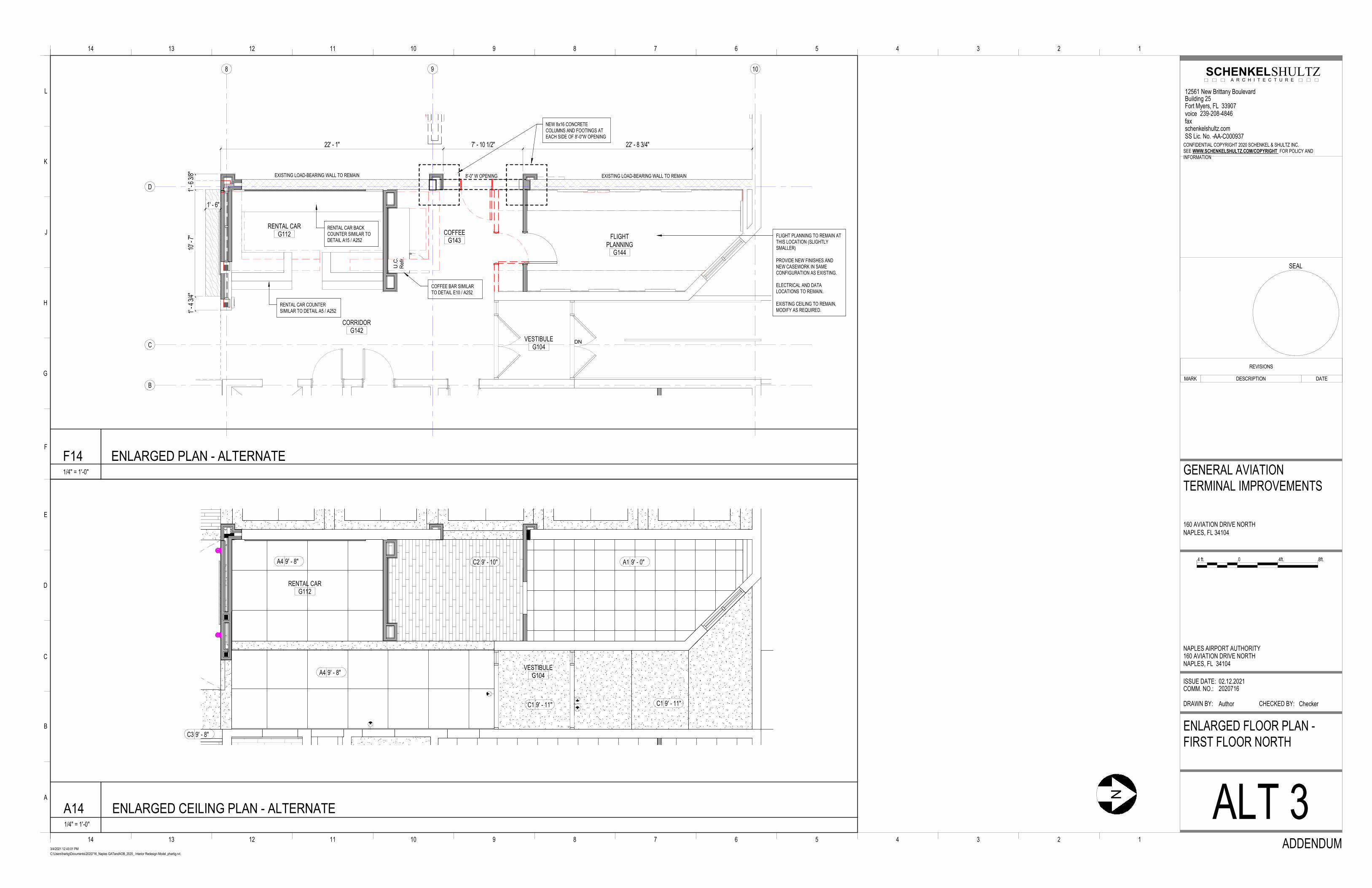
C. Alternate No. 3: Load Bearing Walls at column line D.
1. Base Bid: Per drawings including sheet S101.1G
2. Alternate: The load-bearing wall along column line D remains in-place with an 8’-0”w opening
as shown in the attached updated sketch. Please note that if this alternate is selected:
a. The wall strengthening requirements of sheet S101.1G will not be required.
b. The casework shown in G114 will not be required.
Bidding Contractors: The following GC’s are known plan holders and were in attendance at the site tour. This is not an all-
inclusive list of bidding firms as others may have downloaded plans from the website:
• Owen Ames Kimball Company
• DEC Contracting Group, Inc.
• Allied Contractors, Inc.
• GSD Contracting LLC
The following list represents questions received from bidding contractors and
subcontractors:
1. S101.1G detail 1 legend indicates CMU reinforcing conditions required to be confirmed. A
few questions:
a. Who is to confirm and what are the requirements?
Contractor to confirm and repair referenced locations. Refer to 27/S101.1G
for requirements.
b. What is expected of the contractor to include in the bid for this item?
Assume repair in all locations per 27/S101.1G Repair
Sequence.
c. Are we to cut and patch from the inside, x-ray from the outside, etc?
Contractor’s option based on location and accessibility.
2. There are multiple references made on both the GAT & AOB plans referencing the
landscape plans. I am unable to locate any landscape plans in either set of
drawings. See Addendum 02 for Landscape Plans.
3. There is a note on A201G that indicates to consult with the owner regarding roof
warranty. Please provide the contractor and manufacturer that holds the roofing
warranty for these buildings.
There is not a roof warranty in place.
4. Please provide a toilet accessory schedule.
Toilet accessories in G115, G116 and G118 are existing to remain.
Toilet accessories in G231 and G232 shall be reused after tile installation.
Provide new toilet accessories in A102, A103, A203, A204, G120, G122 per attached
5. Please clarify the badging requirements.
If a construction fence is installed, workers outside inside (land side) of this fence will not
require badging. Badges will be required for all work in the AOA. One security badge can
escort a maximum of 5 construction badges. There is a cost of $50 per badge.
The charge for not returning a badge is $50 per construction badge and $100 per security badge
Addendum #4 General Aviation Terminal and Airport Office Building Improvements Page 2
6. Please clarify where the aluminum framed storefronts are located. I am unable to find a
window schedule and there is specification for aluminum frames storefronts.
There are (2) 4’w x 4’h interior storefront windows in the Line Ops Room, see
interior elevation D18/A253G.
7. Will unit mount or curb mount mechanical equipment screens be considered?
Yes, a unit mounted equipment screen system is preferred to eliminate most, if not all, of the
proposed roof penetrations. Basis of Design - Envisor Cityscapes with sliding access panels,
louvered panel design or equal. System shall be engineered by the manufacturer to meet site
conditions and wind loads.
8. Please clarify on whether the palm design in the terrazzo is a metal outline infilled with TZ-
3? Yes, the palm design is a metal strip pattern infilled with TZ-3. A CAD file can be
provided for layout.
9. Also there are corner guards listed in the specs but I don’t see an elevation showing where
the corner guards are to be placed. This is true for both buildings.
The majority of corner guards will be existing to remain, allow for the following:
GAT First Floor: Allow for 6 new stainless steel corner guards to match existing, locations to
be determined.
GAT Second Floor: no new corner guards required.
AOB: Allow for 4 new corner guards per specifications, locations to be determined.
10. I also need a size for the lockers in the room G122 and G120 in the GAT building
Men and Women lockers shall be double tier 9”w x 15”d x 72”h
11. Life Safety for either building does not show FE or FE cabinets – are these being replaced?
The majority of fire extinguishers will be existing to remain, allow for the following:
GAT First Floor: Allow for 4 new FEC, locations to be determined.
GAT Second Floor: Allow for 1 new FEC, location to be
determined.
AOB: All FE shall be existing to remain.
12. For the acoustical ceiling tile type(s) should I follow the specifications or the reflected ceiling
plans? The specs list 1 type of tile (USG #97241), while the RCPs list 2 different ceiling tiles (A-
1 Fine Fissured 2x2 & A-2 Fine Fissured 4x4). Please advise which type(s) of ceiling tile are
needed.
Ceiling Type A-1 shall be USG 2x2 tegular edge SL (98223),
Ceiling Type A-2 shall match existing tile at second floor of
GAT
Ceiling Type A-4 shall be USG 4x4 tegular edge SL (98443)
13. The Reflected Ceiling Plans reference C2 Wood Wall Planks on the ceilings. The finish
schedule A160G does not show anything for C2. It does list ceiling wall planks as WP-1. Can
you please let me know if C2 from the RCP is what is listed as WP-1 on the finish schedule?
If it does not, please let me know what material should be used for C2 ceiling types.
The ceiling and wall planks (WP-1) shall be use in areas designated as ceiling type C2.
14. Section 01-1000 Page 4 article 1.11B list on-site work hours as 7:00 AM-6:00PM, M-F unless
otherwise indicated. (also weekend work requires approval) At pre-bid walk thru statement
was made work hours are unlimited 24 hours a day 7 days a week. Can this please be
verified?
At pre-bid it was stated that crews could work 24 hours with City approval. We do not
believe this will be a problem due to the isolated location, but it needs to be confirmed with
the City.

Addendum #4 General Aviation Terminal and Airport Office Building Improvements Page 3
15. Is Alternate #2 ONLY for Canopy #2?
Yes, Alternate 2 is for Canopy 2 only
Addenda #3 contains the bid form for the project. The Site Improvement portion of bid form
has stipulated quantities are we to assume the site section will be paid on a unit price basis
(quantities verified in field x unit price given on bid form) or do we price what quantities we
calculate from the drawings?
Site work will be paid on a unit price basis.
16. Addendum #1 contains the master schedule which shows an April 1, 2021 to November 1,
2021 duration for the GAT & AOB Interiors. Item 1.2 states Permit submittal date of Feb
25, 2021 and it appears you are showing a construction start of April 1, 2021 is this
statement correct? In other words, we would anticipate a NTP of April 1, 2021?
NTP for the AOB: April 01, 2021 - NTP for the GAT: May 01, 2021
17. Item 1.5 States “Move GAT staff to AOB” on May 1, 2021 based on the statement in #4 above
we have 30 days (4/1/2021-5/1/2021) to perform all the work and you anticipate re-
occupying the building in 30 days?
Yes, 30 days to complete the second floor interior scope of the AOB. Colors and materials
may need to be substituted in order to meet this schedule. “Off the shelf” cabinets will
also be considered.
18. Item 1.6 shows a 5/1/2021- 11/1/2021 duration for all the interior work related to GAT
building. Is it correct that we cannot start before 5/1/2021 in GAT building?
Correct, the interior work for the GAT cannot begin until administration staff is moved to
the AOB and operations staff moved to the Commercial Terminal.
19. Invitation to Bid item 1.2A states contract duration 4/1/2021-11/15/2021 for a total of 228
days. It also states owner must occupy facility on or before October 29, 2021. Please verify
this date as it is inconsistent with the master schedule.
Substantial completion and TCO by November 01, 2021 with final completion and CO by
November 15, 2021. Move in needs to begin on November 01, 2021.
20. Please verify start of Liquidated damages as three dates can be inferred - October 29, 2021
or November 1, 2021 or November 15, 2021.
Liquidated Damages will be assessed for either missed date above in #19.
21. Master Schedule item 2.4 “revise building permit to include exterior (submit May 01) a date
of June 15, 2021 is shown. Please explain this item. Are you stating you anticipate getting a
revised exterior building permit by 6/15/2021?
Correct
22. Invitation to Bid item 1.4C is very specific in terms of “evidence of competency” which is 3
similar projects in an airport operating environment within the last five (5) years if a bidder
does not meet this requirement will they be considered a “non-responsive bidder”
Modify this section to read …3 similar projects in an airport and/or municipal operating
environment…
23. At the pre bid meeting it was stated that the canopies are not required to be installed by
the liquidated damages date. Please confirm. If this is correct please verify which canopies
do not have to be installed by the liquidated damages date.
It was stated that if submittals and purchase orders were handled in a timely manner and if
components of the canopy are not available, the Authority will work with the contractor to
extend the time for canopies 1 & 2 installation only. Please note that the site work should be
complete with footings in-place, ready for the structure to be attached.
24. In regards to the Master Schedule, Addendum 1, Page 2, Section 1, Article 1.4 “Move
GAT operations to Commercial Terminal”. What does this statement mean to us?

Addendum #4 General Aviation Terminal and Airport Office Building Improvements Page 4
The NAA will move operations to the Commercial terminal. There is no involvement on the
part of the contractor.
25. The Tube Steel Screen wall framing at the roof is listed as AESS, is this correct? The
structural notes say any steel exposed to weather shall be Galvanized, so not sure why this
screen wall framing would be AESS and galvanized. Also, there is no detail for what is
attached to the Tube Steel Screen wall Framing.
Screen wall framing to be AESS –OR- galvanized, columns and beams. The screen
system is addressed in Addendum 02. See also response to item 7 above.
26. The steel canopy framing only list the Columns as AESS, is the correct?
All columns and beams in all canopies to be AESS
27. Can the requirements listed below be waived? AISC Certified Erector. AISC Sophisticated
Paint Endorsement P1 or SSPC-QP3
AISC Certified Erector is recommended but not required. See specifications 09 91 00 for finish
requirements.
28. We are assuming the Canopy Steel Framing is not to be galvanized although it exposed to
the weather, correct?
All columns and beams in all canopies to be AESS
29. The curved tube steel beams at Wave Canopy 2 is listed as HSS steel plate built-up Beams,
we are assuming this is a mistake as none of the other canopy curved tubes for this project
are listed as built-up beams, please clarify.
Wave canopy #2 to be built up curved beams, built up girders and built up columns.
Canopies#1, #3, #4, #5 shall also have built up columns, beams and girders. See plan
30. Please provide contact for building’s existing Fire Alarm vendor.
Wayne Automatic (239) 935-7067, Phil Ciccarello
31. Please provide contact for building’s existing fire sprinkler vendor.
Gulf Fire Protection (239) 643-4881
32. Please provide contact for building’s existing controls/BMS vendor.
N/A
33. Please provide contact for building’s existing security vendor.
IT Vantage, Max Pensy (239) 694-8324
34. If we are to include telco/data scope please provide contact for building existing
Telco/Datavendor.
Centurylink and Crown Castle
The following list represents items discussed at the pre-bid walk-through on February 26,
2021:
35. AOB: What is the finish for the existing hollow metal doors and frames?
All hollow metal doors and frames to be painted, including window frames
36. AOB: Should the old water coolers be reinstalled or provide new
Provide new Elkay EH20 wall mounted ADA water fountain with filtration and bottle
fill station at both floors
37. AOB: What ceiling tiles should be used to replace the existing 2x4’s?
Armstrong Second Look II
38. AOB: What is the extent of the exterior paint?
Paint the entire Airport Office Building and Hangar, including the hangar door
39. AOB: Who will be responsible for disconnecting and reconnecting the ceiling mounted devices

Addendum #4 General Aviation Terminal and Airport Office Building Improvements Page 5
such as cameras, projector, etc…?
IT Vantage, Max Pensy (239) 694-8324
40. AOB: What is the scope for window coverings?
Window blinds are existing to remain at the AOB.
41. AOB and GAT: Is there a NAA access control vendor?
IT Vantage, Max Pensy (239) 694-8324
42. AOB and GAT: Is there an asbestos report available? Will one be required by the City?
An asbestos report, if required, will be provided by the owner.
43. GAT: At room G230, should the old water coolers be reinstalled or provide new?
Provide new Elkay EH20 wall mounted ADA water fountain with filtration and bottle
fill station
44. GAT: What is the floor finish in Corridor 124
Epoxy Floor EXF-1
45. GAT: Should the mirrors in the current Workout room be demolished?
Yes, the mirrors should be removed
46. GAT: What is the scope for window coverings?
All existing window coverings to be demolished. Patch and repair damaged gyp.
board. Owner to provide new window coverings, verify blocking requirements.
47. GAT: There is a generator screen wall shown but no details
The screen wall will not be part of this project. The generator is screened by the existing
landscaping
48. GAT: Who is the manufacturer of the second floor modular office wall system?
Panel Built Incorporated
49. GAT: What is the scope for new tile backing at the existing restrooms?
At rooms G120, G122, G231, G232 remove existing gyp board to 6’ AFF, install tile
backing board
50. GAT: What is the scope for toilet partitions at the existing
restrooms?
At rooms G120, G122 provide new toilet partitions per specifications.
At rooms G231, G232 existing stainless steel toilet partitions shall be reused.
51. Understanding the critical timeline for this project and the fact that the $10,000 each day
liquidated damages is not a penalty; would the Naples Airport Authority consider a reasonable
early completion compensation?
We are considering an early completion incentive, but likely won’t know the amount or how
that is structured until after the bid when we present to the Board.
END OF ADDENDUM #4
DN
U.C
.
Refr
.
8 9
D
C
B
10
22' - 1" 7' - 10 1/2" 22' - 8 3/4"
RENTAL CARG112
VESTIBULEG104
CORRIDORG142
1' - 6"
1' -
6 3/
8"10
' - 7
"1'
- 4
3/4"
FLIGHTPLANNING
G144
COFFEEG143
FLIGHT PLANNING TO REMAIN AT THIS LOCATION (SLIGHTLY SMALLER)
PROVIDE NEW FINISHES AND NEW CASEWORK IN SAME CONFIGURATION AS EXISTING.
ELECTRICAL AND DATA LOCATIONS TO REMAIN.
EXISTING CEILING TO REMAIN, MODIFY AS REQUIRED.
EXISTING LOAD-BEARING WALL TO REMAINEXISTING LOAD-BEARING WALL TO REMAIN
NEW 8x16 CONCRETE COLUMNS AND FOOTINGS AT EACH SIDE OF 8'-0"W OPENING
COFFEE BAR SIMILAR TO DETAIL E10 / A252
RENTAL CAR BACK COUNTER SIMILAR TO DETAIL A15 / A252
RENTAL CAR COUNTER SIMILAR TO DETAIL A5 / A252
8'-0" W OPENING
RENTAL CARG112
VESTIBULEG104
C1 9' - 11" C1 9' - 11"
A4 9' - 8"
C3 9' - 8"
A4 9' - 8" C2 9' - 10" A1 9' - 0"
A
114 2345678910111213
B
C
D
E
F
G
H
J
K
L
114 2345678910111213
COMM. NO.:
DRAWN BY:
ISSUE DATE:
CHECKED BY:
SEAL
SEE WWW.SCHENKELSHULTZ.COM/COPYRIGHT FOR POLICY AND INFORMATION
SS Lic. No. -schenkelshultz.comfaxvoice
SCHENKELSHULTZA R C H I T E C T U R E
C:\Users\hartig\Documents\2020716_Naples GATandAOB_2020_ Interior Redesign Model_phartig.rvt
3/4/2021 12:43:01 PM
2020716
Author
NAPLES AIRPORT AUTHORITY160 AVIATION DRIVE NORTHNAPLES, FL 34104
GENERAL AVIATIONTERMINAL IMPROVEMENTS
160 AVIATION DRIVE NORTHNAPLES, FL 34104
ENLARGED FLOOR PLAN -FIRST FLOOR NORTH
ALT 3ADDENDUM
02.12.2021
Checker
12561 New Brittany BoulevardBuilding 25Fort Myers, FL 33907
239-208-4846
AA-C000937CONFIDENTIAL COPYRIGHT 2020 SCHENKEL & SHULTZ INC.
1/4" = 1'-0"
F14 ENLARGED PLAN - ALTERNATE
0 4ft. 8ft.4 ft.
N
REVISIONS
MARK DESCRIPTION DATE
1/4" = 1'-0"
A14 ENLARGED CEILING PLAN - ALTERNATE

The illustrations and descriptions herein are applicable to production as of the date of this Technical Data Sheet. Rev. 08/17/17 R/B Printed in U.S.A.The manufacturer reserves the right to, and does from time to time, make changes and improvements in designs and dimensions. © 2017 by Bobrick Washroom Equipment, Inc.
Technical Data
continued . . .
MIRROR WITHSTAINLESS STEELCHANNEL FRAME
Designer's Notes:
1. Special-order sizes available on request.
2. Maximum size mirror available, 96" x 72'' (244 x 183cm); minimum size, 12" x 12" (30 x 30cm).
3. All Bobrick framed mirrors are manufactured to overall width and height dimensions. EXAMPLE: A 24" x 36'' (61 x 91cm) mirror will be furnished 24'' x 36'' (61 x 91cm) outside-of-frame to outside-of-frame.
4. To specify special sizes use Series Number followed by width x height in inches. EXAMPLE: B-165 2024 20" x 24" (51 x. 61cm)
5. Bobrick framed mirrors are manufactured to a tolerance 1/8'' (3.2mm).
6. For sufficient space to lift mirror onto wall hanger(s), provide 1" (25mm) minimum clearance above top of mirror frame.
7. Provide 1'' (25mm) minimum clearance at bottom of mirror for unlocking mirror from wall and 1/2'' (12.7mm) minimum clearance on each side.
B-165SERIES
Note: Mirrors greater than 30" in width will have multiple hanger brackets with a typical 8" off each edge.
Slide flat-blade screwdriver or Key between Mirror andWall. Depress Tab on backPanel and remove Mirror. Contact factory for key.
Lock Tab
4-5/8"117mm
3-1/8"79mm
WallBracket
LockTab
MirrorKey
HalfMirror Width
Frame
Mirror
S
S
Finish Face of Wall
1/2''13mm
3/4''19mm
2-1/2''65mm
S
2-9/16''65mm
S
4'' or 5" Typ.100 or 125mm
S
Side ViewBack Plate/Wall Hanger
Frame
Mirror
Finish Face of Wall
B-165 1824 18'' (46cm) 24'' (61cm)B-165 1830 18'' (46cm) 30'' (76cm)B-165 1836 18'' (46cm) 36'' (91cm)B-165 2430 24" (61cm) 30" (76cm)B-165 2436 24'' (61cm) 36'' (91cm)B-165 2448 24'' (61cm) 48'' (122cm)B-165 2460 24'' (61cm) 60'' (152cm)
STANDARD B-165 SERIES MIRRORS
HW
MODEL
NO.
OVERALL SIZE
All Other Size Mirrors
Width Hanger Pockets
Up to 30'' (76cm) 1Over 30" up to 72" (76 to 183cm) 2Over 72" up to 96" (183 to 274cm) 3
Figure: 1
Snap Locking Design
(Rear View)
Figure: 2
Lock Tab Design
(Rear View)
B-165 4836 48'' (122cm) 36'' (91cm)
STANDARD B-165 SERIES MIRRORS
HW
MODEL
NO.
OVERALL SIZE
The illustrations and descriptions herein are applicable to production as of the date of this Technical Data Sheet. B-3699 r4/23/19 Printed in U.S.A.The manufacturer reserves the right to, and does from time to time, make changes and improvements in designs and dimensions. © 2019 by Bobrick Washroom Equipment, Inc.
Technical Data
28''
710mm
10''
255mm
9-1/16''
230mm
S
SS
S
Door
Knob Latch
Paper Towel
Dispenser
Removable
Waste
Receptacle
Finish Face of Wall
4-1/4"
110mm
Reco
mm
en
ded
Mo
un
tin
g H
eig
ht
Off
Flo
or
71''
1805m
m
Reco
mm
en
ded
Mo
un
tin
g H
eig
ht
Off
Flo
or
for
Un
ivers
al / A
ccessib
le D
esig
n
51-1
/2''
1310m
m
28''
710mm
14-1/4''
360mm
S
S
30-7/8''
784mm
48''
1220mm
Max
Mounting Height
(Refer to ADA H/C)
Finish Face of Floor
2-5/8''65mmTyp.
4-1/84''105mm
Typ.
Skirt
MATERIALS:
Cabinet — 18-8, Type-304, 22-gauge (0.8mm) stainless steel. All-welded construction. Exposed surfaces have satin-finish.
Flange — 18-8, Type-304, 22-gauge (0.8mm) stainless steel with satin-finish. Drawn and beveled, one-piece, seamless construction.
Skirt — 18-8, Type-304, 22-gauge (0.8mm) stainless steel with satin-finish.
Door — 18-8, Type-304, 22-gauge (0.8mm) stainless steel with satin-finish. Secured to cabinet with a full-length, stainless steel piano-hinge. Equipped with a knob latch.
Paper Towel Dispenser — 18-8, Type-304, 22-gauge (0.8mm) stainless steel with satin-finish. Capacity: 350 C-fold or 475 multifold paper towels.
Waste Receptacle — 18-8, Type-304, Heavy-gauge stainless steel with satin-finish. Top edges are hemmed for safe handling. Retaining Hook. Capacity: 2-gal. (7.6-L).
Optional: Order Bobrick Model No. 369-130 TowelMate® available as an optional accessory. TowelMate accessory allows for paper towels to dispense one at time without bulging or sagging, or falling through the towel tray opening. The 90 degree return on the towel guide prevents papers from falling forward and out when door is opened for servicing.
OPERATION:
Paper towel dispenser will dispense C-fold or multifold paper towels without adjustment. Rounded towel tray has hemmed opening to dispense paper towels without tearing. Waste receptacle is retained in cabinet by a retaining hook feature and is removable for servicing.
INSTALLATION:
Mount unit on wall with #8 x 1-1/4" sheet-metal screws (not furnished) at points indicated by an S. For plaster or dry wall construction, provide concealed backing to comply with local building codes, then secure unit with sheet-metal screws. For other wall surfaces, provide fiber plugs or expansion shields for use with sheet-metal screws, or provide 1/8" (3mm) toggle bolts or expansion bolts. If unit projects above top of wainscot, provide aluminum channel or other filler to eliminate gap between unit and finish face of wall.
SPECIFICATION:
Surface-mounted paper towel dispenser and waste receptacle shall be Type-304 stainless steel with all-welded construction; exposed surfaces shall have satin-finish. Flange shall be drawn, one-piece, seamless construction. Door shall be secured to cabinet with a full-length, stainless steel piano-hinge, and equipped with a knob latch. Paper towel dispenser shall dispense 350 C-fold or 475 multifold paper towels without adjustment or use of adapters. Removable stainless steel waste receptacle shall be retained in cabinet by a retaining hook feature, have top edges hemmed for safe handling; and shall have a minimum capacity of 2-gal. (7.6-L).
Surface-Mounted Paper Towel Dispenser And Waste Receptacle shall be Model B-3699 of Bobrick Washroom Equipment, Inc., Clifton Park, New York; Jackson, Tennessee; Los Angeles, California; Bobrick Washroom Equipment Company, Scarborough, Ontario; Bobrick Washroom Equipment Pty. Ltd., Australia; and Bobrick Washroom Equipment Limited, United Kingdom.
ClassicSeries®
SURFACE-MOUNTED
PAPER TOWEL DISPENSER
AND WASTE RECEPTACLE
B-3699

The illustrations and descriptions herein are applicable to production as of the date of this Technical Data Sheet. Rev. 11/11/19S/B Printed in U.S.A.The manufacturer reserves the right to, and does from time to time, make changes and improvements in designs and dimensions. © 2019 by Bobrick Washroom Equipment, Inc.
Technical Data
L
L
Edge of
Flange to Wall
36''915mm
4''100mm
39-3/4''1010mm 57-3/4''
1465mm
50''1270mm
Edge of
Flange to Wall
Edge of
Flange to Wall
32''815mm
4''100mm
39-3/4''1010mm
27-3/4''705mm
24''610mm
Edge of
Flange to Wall
continued . . .
42''1065mm
4''100mm
50''1270mm
57-3/4''1465mm
45-3/4''1160mm
Edge ofFlange to Wall
Edge ofFlange to Wall
2''50mm
2-1/4''55mm
3-1/8''80mm
5/16''8mm
Snap Flange Cover
3-1/4''85mm
Dia.
1-1/2''38mm
End Mounting Flange
3-1/8''80mm
Intermediate Flange
2-5/8''65mm
2-1/4''55mm
3-1/8''80mm
1¼" (32mm) DIAMETERSTAINLESS STEEL GRAB BARS
WITH SNAP FLANGE
B-5806SERIES
Satin-finish, slip-resistant surface.
Peened surface; add suffix .99 to model number
Specify Finish Required:
HORIZONTAL VERTICAL
B-5806 x 18, 24, 30, 36, 42, 48
TWO-WALLTUB / SHOWER
COMPARTMENT BAR
B-5837
HORIZONTALTUB / SHOWER
COMPARTMENT BAR 24 x 36
B-58616
TWO-WALLTOILET COMPARTMENT BAR 42 x 54
B-5897
The illustrations and descriptions herein are applicable to production as of the date of this Technical Data Sheet. B-5806 r11/11/19S/B Printed in U.S.A.The manufacturer reserves the right to, and does from time to time, make changes and improvements in designs and dimensions. © 2019 by Bobrick Washroom Equipment, Inc.
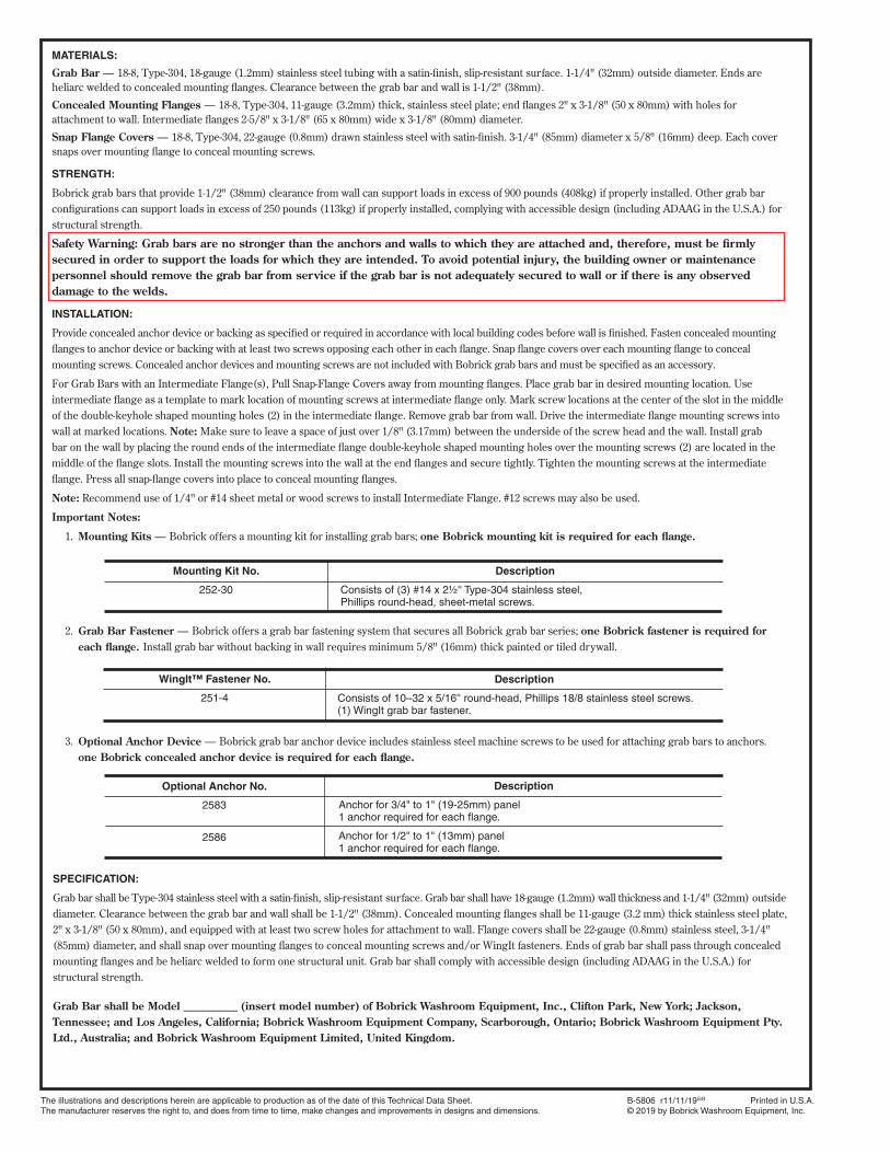
MATERIALS:
Grab Bar — 18-8, Type-304, 18-gauge (1.2mm) stainless steel tubing with a satin-finish, slip-resistant surface. 1-1/4" (32mm) outside diameter. Ends are
heliarc welded to concealed mounting flanges. Clearance between the grab bar and wall is 1-1/2" (38mm).
Concealed Mounting Flanges — 18-8, Type-304, 11-gauge (3.2mm) thick, stainless steel plate; end flanges 2" x 3-1/8" (50 x 80mm) with holes for
attachment to wall. Intermediate flanges 2-5/8" x 3-1/8" (65 x 80mm) wide x 3-1/8" (80mm) diameter.
Snap Flange Covers — 18-8, Type-304, 22-gauge (0.8mm) drawn stainless steel with satin-finish. 3-1/4" (85mm) diameter x 5/8" (16mm) deep. Each cover
snaps over mounting flange to conceal mounting screws.
STRENGTH:
Bobrick grab bars that provide 1-1/2" (38mm) clearance from wall can support loads in excess of 900 pounds (408kg) if properly installed. Other grab bar
configurations can support loads in excess of 250 pounds (113kg) if properly installed, complying with accessible design (including ADAAG in the U.S.A.) for
structural strength.
Safety Warning: Grab bars are no stronger than the anchors and walls to which they are attached and, therefore, must be firmly
secured in order to support the loads for which they are intended. To avoid potential injury, the building owner or maintenance
personnel should remove the grab bar from service if the grab bar is not adequately secured to wall or if there is any observed
damage to the welds.
INSTALLATION:
Provide concealed anchor device or backing as specified or required in accordance with local building codes before wall is finished. Fasten concealed mounting
flanges to anchor device or backing with at least two screws opposing each other in each flange. Snap flange covers over each mounting flange to conceal
mounting screws. Concealed anchor devices and mounting screws are not included with Bobrick grab bars and must be specified as an accessory.
For Grab Bars with an Intermediate Flange(s), Pull Snap-Flange Covers away from mounting flanges. Place grab bar in desired mounting location. Use
intermediate flange as a template to mark location of mounting screws at intermediate flange only. Mark screw locations at the center of the slot in the middle
of the double-keyhole shaped mounting holes (2) in the intermediate flange. Remove grab bar from wall. Drive the intermediate flange mounting screws into
wall at marked locations. Note: Make sure to leave a space of just over 1/8'' (3.17mm) between the underside of the screw head and the wall. Install grab
bar on the wall by placing the round ends of the intermediate flange double-keyhole shaped mounting holes over the mounting screws (2) are located in the
middle of the flange slots. Install the mounting screws into the wall at the end flanges and secure tightly. Tighten the mounting screws at the intermediate
flange. Press all snap-flange covers into place to conceal mounting flanges.
Note: Recommend use of 1/4'' or #14 sheet metal or wood screws to install Intermediate Flange. #12 screws may also be used.
Important Notes:
1. Mounting Kits — Bobrick offers a mounting kit for installing grab bars; one Bobrick mounting kit is required for each flange.
2. Grab Bar Fastener — Bobrick offers a grab bar fastening system that secures all Bobrick grab bar series; one Bobrick fastener is required for
each flange. Install grab bar without backing in wall requires minimum 5/8" (16mm) thick painted or tiled drywall.
3. Optional Anchor Device — Bobrick grab bar anchor device includes stainless steel machine screws to be used for attaching grab bars to anchors.
one Bobrick concealed anchor device is required for each flange.
SPECIFICATION:
Grab bar shall be Type-304 stainless steel with a satin-finish, slip-resistant surface. Grab bar shall have 18-gauge (1.2mm) wall thickness and 1-1/4" (32mm) outside
diameter. Clearance between the grab bar and wall shall be 1-1/2" (38mm). Concealed mounting flanges shall be 11-gauge (3.2 mm) thick stainless steel plate,
2" x 3-1/8" (50 x 80mm), and equipped with at least two screw holes for attachment to wall. Flange covers shall be 22-gauge (0.8mm) stainless steel, 3-1/4"
(85mm) diameter, and shall snap over mounting flanges to conceal mounting screws and/or WingIt fasteners. Ends of grab bar shall pass through concealed
mounting flanges and be heliarc welded to form one structural unit. Grab bar shall comply with accessible design (including ADAAG in the U.S.A.) for
structural strength.
Grab Bar shall be Model __________ (insert model number) of Bobrick Washroom Equipment, Inc., Clifton Park, New York; Jackson,
Tennessee; and Los Angeles, California; Bobrick Washroom Equipment Company, Scarborough, Ontario; Bobrick Washroom Equipment Pty.
Ltd., Australia; and Bobrick Washroom Equipment Limited, United Kingdom.
Description
Consists of 10–32 x 5/16'' round-head, Phillips 18/8 stainless steel screws. (1) WingIt grab bar fastener.
WingIt™ Fastener No.
251-4
Mounting Kit No.
252-30
Description
Consists of (3) #14 x 2½'' Type-304 stainless steel,Phillips round-head, sheet-metal screws.
Description
Anchor for 3/4" to 1" (19-25mm) panel1 anchor required for each flange.
Anchor for 1/2" to 1" (13mm) panel1 anchor required for each flange.
Optional Anchor No.
2583
2586
The illustrations and descriptions herein are applicable to production as of the date of this Technical Data Sheet. Revised 1/22/18R/B, S/H Printed in U.S.A.The manufacturer reserves the right to, and does from time to time, make changes and improvements in designs and dimensions. © 2018 by Bobrick Washroom Equipment, Inc.
Technical Data
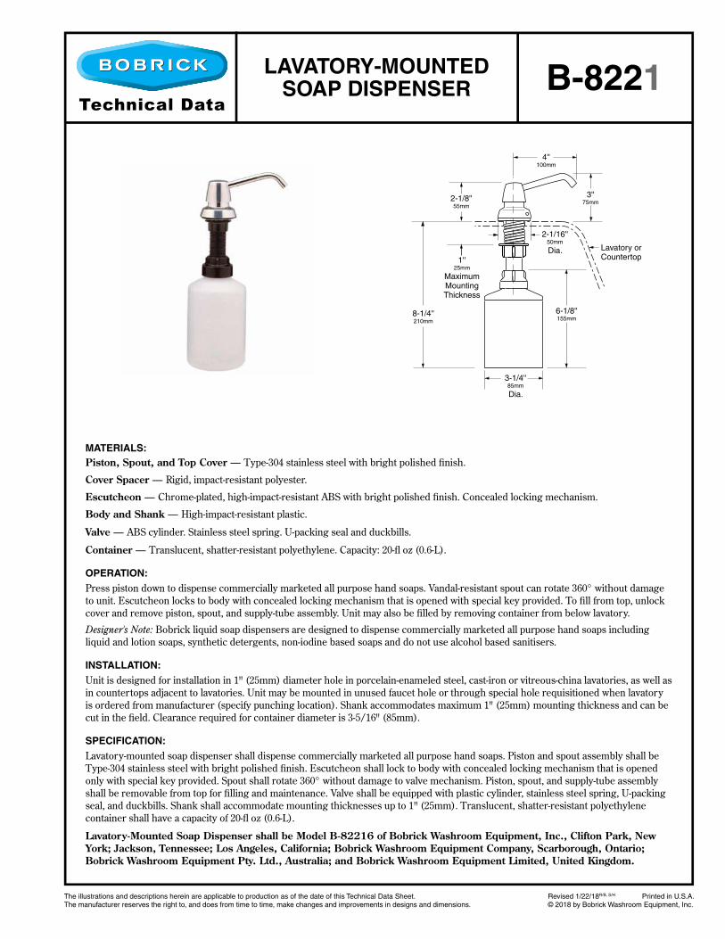
4''100mm
3''75mm
2-1/8''55mm
1''25mm
MaximumMountingThickness
2-1/16''50mm
Dia.
8-1/4''210mm
Lavatory orCountertop
6-1/8''155mm
3-1/4''85mm
Dia.
MATERIALS:
Piston, Spout, and Top Cover — Type-304 stainless steel with bright polished fi nish.
Cover Spacer — Rigid, impact-resistant polyester.
Escutcheon — Chrome-plated, high-impact-resistant ABS with bright polished fi nish. Concealed locking mechanism.
Body and Shank — High-impact-resistant plastic.
Valve — ABS cylinder. Stainless steel spring. U-packing seal and duckbills.
Container — Translucent, shatter-resistant polyethylene. Capacity: 20-fl oz (0.6-L).
OPERATION:
Press piston down to dispense commercially marketed all purpose hand soaps. Vandal-resistant spout can rotate 360° without damage
to unit. Escutcheon locks to body with concealed locking mechanism that is opened with special key provided. To fi ll from top, unlock
cover and remove piston, spout, and supply-tube assembly. Unit may also be fi lled by removing container from below lavatory.
Designer's Note: Bobrick liquid soap dispensers are designed to dispense commercially marketed all purpose hand soaps including
liquid and lotion soaps, synthetic detergents, non-iodine based soaps and do not use alcohol based sanitisers.
INSTALLATION:
Unit is designed for installation in 1" (25mm) diameter hole in porcelain-enameled steel, cast-iron or vitreous-china lavatories, as well as
in countertops adjacent to lavatories. Unit may be mounted in unused faucet hole or through special hole requisitioned when lavatory
is ordered from manufacturer (specify punching location). Shank accommodates maximum 1" (25mm) mounting thickness and can be
cut in the fi eld. Clearance required for container diameter is 3-5/16" (85mm).
SPECIFICATION:
Lavatory-mounted soap dispenser shall dispense commercially marketed all purpose hand soaps. Piston and spout assembly shall be
Type-304 stainless steel with bright polished fi nish. Escutcheon shall lock to body with concealed locking mechanism that is opened
only with special key provided. Spout shall rotate 360° without damage to valve mechanism. Piston, spout, and supply-tube assembly
shall be removable from top for fi lling and maintenance. Valve shall be equipped with plastic cylinder, stainless steel spring, U-packing
seal, and duckbills. Shank shall accommodate mounting thicknesses up to 1" (25mm). Translucent, shatter-resistant polyethylene
container shall have a capacity of 20-fl oz (0.6-L).
Lavatory-Mounted Soap Dispenser shall be Model B-82216 of Bobrick Washroom Equipment, Inc., Clifton Park, New
York; Jackson, Tennessee; Los Angeles, California; Bobrick Washroom Equipment Company, Scarborough, Ontario;
Bobrick Washroom Equipment Pty. Ltd., Australia; and Bobrick Washroom Equipment Limited, United Kingdom.
LAVATORY-MOUNTED
SOAP DISPENSER B-8221

continued . . .
The illustrations and descriptions herein are applicable to production as of the date of this Technical Data Sheet. Revised 2/21/19 Printed in U.S.A.The manufacturer reserves the right to, and does from time to time, make changes and improvements in designs and dimensions. © 2019 by Bobrick Washroom Equipment, Inc.
Technical Data
SS
S
8-35/64"(217mm)
0-5/8"(16mm)
2-9/16"(65mm)
10-15/64"(260mm)
4-1/4"(108mm)
6-1/32"(153mm)
4-9/16"(116mm)
12-13/64"(310mm)
Finish Face of WallDrilling Specifications
11-11/16"(297mm)
3-25/32"(96mm)
Reco
mm
en
ded
Mo
un
tin
g H
eig
ht
Off
Flo
or
39"-
43
" (1
00-1
10cm
)
Plastic
ContainerLock
& Key
TrimLineSeriesTM
SURFACE-MOUNTEDLIQUID SOAP DISPENSER
500ML
MATERIAL:
Welded, 0.8mm (22 gauge) 1.4301, Typ CrNi 18/10, AISI 304 stainless steel housing with satin finish; stainless steel operating lever; metal lock and key; soap level indicator; interchangeable plastic containers with plastic pumps; variety of plastic containers available including containers with pumps for soap or foam.
OPERATION:
The cover is lockable with a Bobrick System lock. To refill the dispenser, open the cover by lifting and pulling forward. The soap level
indicator shows how much product is remaining in the dispenser. The plastic container can be removed and re-installed for quick and
easy refilling of up to 500 ml of bulk liquid soap. Alternatively, soap can be poured directly into the plastic container. The dispenser has
been designed for quick and easy refilling process.
INSTALLATION:
After opening the dispenser cover, remove the plastic container, gently lifting it upwards while pressing the locking latch. Mount the
dispenser to the wall by using the enclosed screws and wall plugs. Make sure the wall surface is in good condition to ensure proper
mating of the dispenser to the wall. Use silicone or glue pads if necessary.
Note:
1. The dispenser should be installed near or directly above the sink to allow wet hands to drip into the sink.
2. Allow sufficient space above dispenser to exchange cartridges easily.
3. Recommended installation height: 39" - 43" (100 – 110 cm) (measured from floor to the bottom of the dispenser).
TECHNICAL SPECIFICATIONS:
Model B-26607 from Bobrick Washroom Equipment, Dispenser made of 0.8 mm thick, (22 gauge) 1.4301, Type CrNi 18/10, AISI 304
stainless steel with a brushed, satin finish; plastic container for soap cartridges (up to 500 ml), as well as for bulk refill of soap (up to
500 ml); lockable with a Bobrick System lock; soap level indicator.
CARE INSTRUCTIONS:
Clean regularly with warm water and/or stainless steel cleaner.
Do not use acid (chloride) cleaners or scouring agents.
The suction valve can be cleansed by pumping hot water through it.
Do not dismantle the dispenser.
Use only original spare parts.
Liquid Soap Dispenser shall be Model B-26607 of Bobrick Washroom Equipment, Inc., Clifton Park, New York;
Jackson, Tennessee; Los Angeles, California; Bobrick Washroom Equipment Company, Scarborough, Ontario; Bobrick
Washroom Equipment Pty. Ltd., Australia; and Bobrick Washroom Equipment Limited, United Kingdom.
B-26607

In the U.S.A.: BOBRICK WASHROOM EQUIPMENT, INC.
200 Commerce Drive, Clifton Park, New York 12065-1350 • Tel: 518/877-7444 • FAX: 518-877-5029
6901 Tujunga Avenue, North Hollywood, California 91605-6213 • Tel: 818-982-9600 • FAX: 818-503-1102
or email: [email protected]
In Canada: BOBRICK WASHROOM EQUIPMENT COMPANY
45 Rolark Drive, Scarborough, Ontario M1R 3B1 • Fax: (877) 423-8555
© 2019 by Bobrick Washroom Equipment, Inc.
B-26607 r2/21/19 Printed in U.S.A.
1. Install dispenser near or directly above sink to allow wet hands to drip into sink.
2. Allow sufficient space above dispenser to exchange cartridges easily.
3. Recommended installation height: 39" - 43" (100 – 110 cm)(measured from floor to bottom of dispenser).
4. For installation please follow instructions down below:
B. Press locking latch and lift cartridge
up and out.
A. To change cartridge: open dispenser.
5. Press lever several times
to prime pump.
4. Replace dispenser cover.3. Ensure both top and
bottom of container are
correctly seated in dispenser.
2. Insert plastic container
into dispenser.
1. Mount dispenser to wall
using enclosed screws and
wall plugs.
INSTALLATION INSTRUCTIONS
BOBRICK SURFACE-MOUNTED SOAP DISPENSER

KB310-SSWM Baby Changing Station Technical Data Sheet
*Diagrams are not to scale.
23 1/8"(587mm)
44"(1118mm)

KB310-SSWM Baby Changing Station Closed Position
*Diagrams are not to scale.
41 15/32" (1053mm)
26 11/32"(669mm)
23 1/8"(587mm)
29 3/4"(756mm)
35 23/32"(907mm)
6 5/8"(168mm)
2 23/32"(69mm)
3 27/32"(98mm)
1/4"(6mm)
47 7/16"(1205mm)
to skirt mounting
*Diagrams are not to scale.
KB310-SSWM Baby Changing Station Open Position
30 1/8"(765mm)
16"(406mm)
33 1/8"(841mm)
17 13/32"(442mm)
2 13/16"(71mm)
2 7/16"(62mm)
9 31/32"(253mm)
2 31/32"(75mm)
2 3/4"(70mm)
28"(711mm)
30 13/16"(783mm)
25 9/16"(649mm)
©2020 Koala Kare Products, KB310-SSWM TDS December 2020
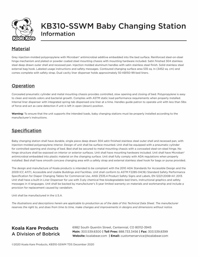
Material
Grey injection-molded polypropylene with Microban® antimicrobial additive embedded into the bed surface. Reinforced steel-on-steel
hinge mechanism and plated or powder coated steel mounting chassis with mounting hardware included. Satin finished 304 stainless
steel deep drawn outer shell and recessed pan. Injection molded aluminum handles with satin stainless steel finish. Solid stainless steel
external bag hook. Labeled usage instructions and safety messages. Contoured changing surface area 535 sq. In (3452 sq. cm) and
comes complete with safety strap. Dual cavity liner dispenser holds approximately 50 KB150-99 bed liners.
Operation
Concealed pneumatic cylinder and metal mounting chassis provides controlled, slow opening and closing of bed. Polypropylene is easy
to clean and resists odors and bacterial growth. Complies with ASTM static load performance requirements when properly installed.
Internal liner dispenser with integrated spring tab dispensed one liner at a time. Handles guide patron to operate unit with less than 5lbs
of force and act as cane detection if unit is left in open (down) position.
Warning: To ensure that the unit supports the intended loads, baby changing stations must be properly installed according to the
manufacturer’s instructions.
Specification
Baby changing station shall have durable, single piece deep drawn 304 satin finished stainless steel outer shell and recessed pan, with
injection-molded polypropylene interior. Design of unit shall be surface-mounted. Unit shall be equipped with a pneumatic cylinder
for controlled opening and closing of bed. Bed shall be secured to metal mounting chassis with a concealed steel-on-steel hinge. No
hinge structure shall be exposed on interior or exterior surfaces. Unit shall have mounting hardware included. Unit shall have Microban®
antimicrobial embedded into plastic material on the changing surface. Unit shall fully comply with ADA regulations when properly
installed. Bed shall have smooth concave changing area with a safety strap and external stainless steel hook for bags or purse provided.
The design and manufacture of Koala products is intended to be compliant with the 2010 ADA Standards for Accessible Design and the
2009 ICC A117.1, Accessible and Usable Buildings and Facilities. Unit shall conform to ASTM F2285-04(16) Standard Safety Performance
Specification for Diaper Changing Tables for Commercial Use, ANSI Z535.4 Product Safety Signs and Labels, EN 12221:2008+A1: 2013.
Unit shall have a built-in Liner Dispenser for use with 3-ply chemical free biodegradable bed liners, instructional graphics and safety
messages in 4 languages. Unit shall be backed by manufacturer’s 5-year limited warranty on materials and workmanship and include a
provision for replacement caused by vandalism.
Unit shall be manufactured in the U.S.A.
The illustrations and descriptions herein are applicable to production as of the date of this Technical Data Sheet. The manufacturer
reserves the right to, and does from time to time, make changes and improvements in designs and dimensions without notice.
KB310-SSWM Baby Changing Station Information
Koala Kare Products
A Division of Bobrick
6982 South Quentin Street, Centennial, CO 80112-3945
Main: 303.539.8300 | Toll Free: 888.733.3456 | Fax: 303.539.8399
Website: koalabear.com | Email: [email protected]

The illustrations and descriptions herein are applicable to production as of the date of this Technical Data Sheet. Revised 8/6/14 Printed in U.S.A.The manufacturer reserves the right to, and does from time to time, make changes and improvements in designs and dimensions. © 2014 by Bobrick Washroom Equipment, Inc.
Technical Data
1-3/16''30mm
Typ.
10-11/16''270mm
S
15-1/8''385mm
Lock& Key
SanitaryNapkin
DisposalPanel
Door
RemovableWaste Receptacle
S
Re
co
mm
en
de
d M
ou
nti
ng
He
igh
t O
ff F
loo
rF
or
Un
ive
rsa
l /
Ac
ce
ss
ible
De
sig
n
30
''
76
0m
m
7-9/16''190mm
Typ.
S
3-15/16''100mm
Typ.
Finish Face of Wall
4-1/16''105mm
MATERIALS:
Cabinet — 18-8, type-304, heavy-gauge stainless steel. All-welded construction. Exposed surfaces have satin finish.
Door — 18-8, type-304, 22-gauge (0.8mm) stainless steel with satin finish. Secured to cabinet with a full-length stainless steel
piano-hinge. Equipped with a tumbler lock keyed like other Bobrick washroom accessories.
Disposal Panels (2) — 18-8, type-304, 22-gauge (0.8mm) stainless steel with satin finish. Bottom edges hemmed for safety.
Secured to door and permanent panel with spring-loaded, full-length stainless steel piano-hinge. Equipped with international
graphic symbol identifying sanitary napkin disposal.
Waste Receptacle — Leak-proof, rigid molded polyethylene. Removable for servicing. Capacity: 1.2-gal. (4.6-L).
OPERATION:
Unit is equipped with a self-closing panel covering each disposal opening. Napkin disposal is emptied by opening door with furnished
key and removing waste receptacle.
INSTALLATION:
For partitions with particle-board or other solid core, secure with four #8 x 1-1/4" (4.2 x 32mm) sheet=metal screws (not furnished), or
provide through-bolts, nuts, and washers.
For hollow-core metal partitions, provide solid backing into which sheet-metal screws can be secured. If two units are installed back-to-
back, then provide threaded sleeves and machine screws for the full thickness of partition.
For plaster or dry wall construction, provide concealed backing to comply with local building coeds, then secure unit with #8 x 1-1/4"
(4.2 x 32mm) sheet-metal screws.
For other wall surfaces, provide fiber plugs or expansion shields for use with #8 x 1-1/4" (4.2 x 32mm) sheet-metal screws, or provide
3/16" (5mm) toggle bolts or expansion bolts.
SPECIFICATION:
Surface-mounted sanitary napkin disposal shall be type-304 stainless steel with all-welded construction; exposed surfaces shall have
satin finish. Door shall be secured to cabinet with a full-length stainless steel piano-hinge and equipped with a tumbler lock keyed like
other Bobrick washroom accessories. Unit shall have a self-closing panel covering each disposal opening. Panel shall have bottom
edge hemmed for safety, be secured to door with spring-loaded, full-length stainless steel piano-hinge, and equipped with international
graphic symbols identifying sanitary napkin disposal. Unit shall be furnished with a removable, leak-proof molded polyethylene recep-
tacle. Receptacle shall have a capacity of 1.2-gal. (4.6-L).
Surface-Mounted Sanitary Napkin Disposal shall be Model B-254 of Bobrick Washroom Equipment, Inc., Clifton Park,
New York; Jackson, Tennessee; Los Angeles, California; Bobrick Washroom Equipment Company, Scarborough, Ontario;
Bobrick Washroom Equipment Pty. Ltd., Australia; and Bobrick Washroom Equipment Limited, United Kingdom.
SURFACE-MOUNTED
SANITARY NAPKIN
DISPOSALB-254

The illustrations and descriptions herein are applicable to production as of the date of this Technical Data Sheet. Revised 5/19/17 Printed in U.S.A.The manufacturer reserves the right to, and does from time to time, make changes and improvements in designs and dimensions. © 2017 by Bobrick Washroom Equipment, Inc.
Technical Data
13-11/16"345mm
4-5/8"115mm
8-1/2"215mm
4-1/2"115mm
2-3/16"55mm
4-13/16"125mm
10"255mm
Lock and Key
1-3/16" 30mm
Finish Face of Wall
4-3/8"110mm
30"
760m
m
Reco
mm
en
ded
Mo
un
tin
g H
eig
ht
Off
Flo
or
Reco
mm
en
ded
Mo
un
tin
g H
eig
ht
Off
Flo
or
for
Accessib
le D
esig
n
25"
635 m
m
Spindle
MATERIALS:
Cabinet — 18-8, Type-304, heavy-gauge stainless steel. All-welded construction. Exposed surfaces have satin-finish.
Skirt — 18-8, Type-304, stainless steel with satin-finish.
Door — 18-8, Type-304, 20-gauge (0.9mm) stainless steel with satin-finish. Secured to cabinet with two rivets. Equipped with a tumbler lock keyed like other Bobrick washroom accessories.
Spindle — 18-8, Type-304, 18-gauge (1.2mm), 1" diameter (25mm) stainless steel tubing with plastic end caps. Theft resistant. Removable with key provided.
OPERATION:
Unit holds two standard-core toilet tissue rolls up to 5-1/8" (130mm) diameter (1500 sheets). To service toilet tissue dispenser, unlock door with key provided and slide spindle out on any direction.
INSTALLATION:
For partitions with particleboard or other solid core, secure with four #10 x 5/8" (4.8 x 16mm) sheet-metal screws (not furnished) at points indicated by an S, or provide through-bolts, nuts, and washers.
For hollow-core metal partitions, provide solid backing into which sheet-metal screws can be secured. If two units are installed back-to-back, then provide threaded sleeves and machine screws for the full thickness of partition.
For plaster or dry wall construction, provide concealed backing to comply with local building codes, then secure unit with sheet-metal screws.
For other wall surfaces, provide fiber plugs or expansion shields for use with sheet-metal screws, or provide 3/16" (5mm) toggle bolts or
expansion bolts.
Replacement Parts:
Knob Latch 2621-8Spindle 3588-33Skirt Kit 3588-53 Door Replacement Kit 3588-73 Lock and Key 388-42
SPECIFICATION:
Surface-mounted multi-roll toilet tissue dispenser shall be Type-304 stainless steel with all-welded construction; exposed surfaces shall have satin finish. Door shall be Type-304, 20-gauge (0.9mm) secured to cabinet with two rivets; and equipped with a tumbler lock keyed like other Bobrick washroom accessories. Spindle shall be Type-304, 18-gauge (1.2mm), 1" diameter (25mm) stainless steel. Theft resistant, removable with key provided.
TrimLine Surface-Mounted Multi-Roll Toilet Tissue Dispenser shall be Model B-3588 of Bobrick Washroom Equipment, Inc., Clifton Park, New York; Jackson, Tennessee; Los Angeles, California; Bobrick Washroom Equipment Company, Scarborough, Ontario; Bobrick Washroom Equipment Pty. Ltd., Australia; and Bobrick Washroom Equipment Limited, United Kingdom.
TrimLineSeries™
SURFACE-MOUNTED
MULTI-ROLL
TOILET TISSUE DISPENSER
B-3588
The illustrations and descriptions herein are applicable to production as of the date of this Technical Data Sheet. B-165 Rev. 8/17/17 R/B Printed in U.S.A.The manufacturer reserves the right to, and does from time to time, make changes and improvements in designs and dimensions. © 2017 by Bobrick Washroom Equipment, Inc.
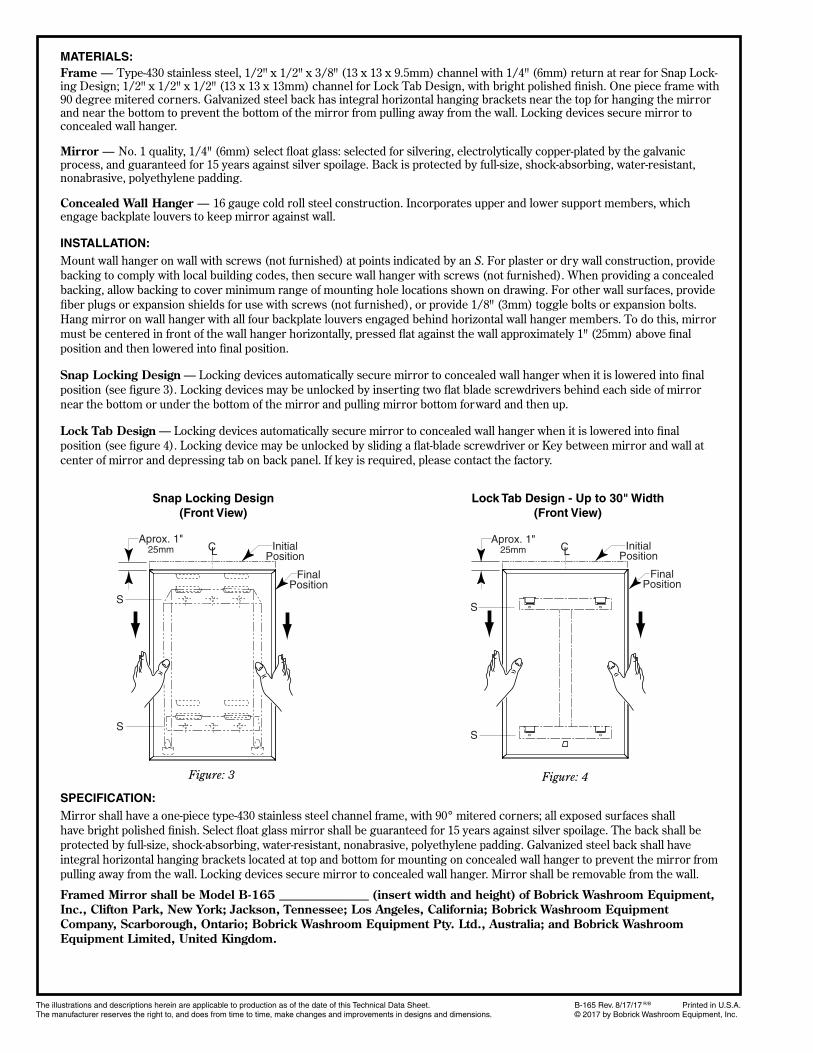
MATERIALS:
Frame — Type-430 stainless steel, 1/2" x 1/2" x 3/8" (13 x 13 x 9.5mm) channel with 1/4" (6mm) return at rear for Snap Lock-ing Design; 1/2" x 1/2" x 1/2" (13 x 13 x 13mm) channel for Lock Tab Design, with bright polished finish. One piece frame with 90 degree mitered corners. Galvanized steel back has integral horizontal hanging brackets near the top for hanging the mirror and near the bottom to prevent the bottom of the mirror from pulling away from the wall. Locking devices secure mirror to concealed wall hanger.
Mirror — No. 1 quality, 1/4" (6mm) select float glass: selected for silvering, electrolytically copper-plated by the galvanic process, and guaranteed for 15 years against silver spoilage. Back is protected by full-size, shock-absorbing, water-resistant, nonabrasive, polyethylene padding.
Concealed Wall Hanger — 16 gauge cold roll steel construction. Incorporates upper and lower support members, which engage backplate louvers to keep mirror against wall.
INSTALLATION:
Mount wall hanger on wall with screws (not furnished) at points indicated by an S. For plaster or dry wall construction, provide
backing to comply with local building codes, then secure wall hanger with screws (not furnished). When providing a concealed
backing, allow backing to cover minimum range of mounting hole locations shown on drawing. For other wall surfaces, provide
fiber plugs or expansion shields for use with screws (not furnished), or provide 1/8" (3mm) toggle bolts or expansion bolts.
Hang mirror on wall hanger with all four backplate louvers engaged behind horizontal wall hanger members. To do this, mirror
must be centered in front of the wall hanger horizontally, pressed flat against the wall approximately 1" (25mm) above final
position and then lowered into final position.
Snap Locking Design — Locking devices automatically secure mirror to concealed wall hanger when it is lowered into final
position (see figure 3). Locking devices may be unlocked by inserting two flat blade screwdrivers behind each side of mirror
near the bottom or under the bottom of the mirror and pulling mirror bottom forward and then up.
Lock Tab Design — Locking devices automatically secure mirror to concealed wall hanger when it is lowered into final
position (see figure 4). Locking device may be unlocked by sliding a flat-blade screwdriver or Key between mirror and wall at
center of mirror and depressing tab on back panel. If key is required, please contact the factory.
SPECIFICATION:
Mirror shall have a one-piece type-430 stainless steel channel frame, with 90° mitered corners; all exposed surfaces shall
have bright polished finish. Select float glass mirror shall be guaranteed for 15 years against silver spoilage. The back shall be
protected by full-size, shock-absorbing, water-resis tant, nonabrasive, polyethylene padding. Galvanized steel back shall have
integral horizontal hanging brackets located at top and bottom for mounting on concealed wall hanger to prevent the mirror from
pulling away from the wall. Locking devices secure mirror to concealed wall hanger. Mirror shall be removable from the wall.
Framed Mirror shall be Model B-165 _______________ (insert width and height) of Bobrick Washroom Equipment,
Inc., Clifton Park, New York; Jackson, Tennessee; Los Angeles, California; Bobrick Washroom Equipment
Company, Scarborough, Ontario; Bobrick Washroom Equipment Pty. Ltd., Australia; and Bobrick Washroom
Equipment Limited, United Kingdom.
Aprox. 1"25mm Initial
Position
S
S
FinalPosition
CLAprox. 1"
25mm InitialPosition
S
S
FinalPosition
CL
Figure: 3 Figure: 4
Lock Tab Design - Up to 30" Width
(Front View)
Snap Locking Design
(Front View)