adcp.12a.01 - taoglas · spe -19 8 007 /a pf 4 the adcp.12 is produced in a ts16949-compliant...
TRANSCRIPT

SPE-19-98-007-A-PF
ADCP.12A.01.3000K
Part No:
ADCP.12A.01.3000K
Description:
Active 5.9GHz DSRC Patch Antenna 12*12*4mm on PCB 50*50mm 150mm RG-316 SMA(M)
Features:
5850MHz to 5925MHz band
For DSRC and CB2X Applications
Transmit and Receive Amplifiers
Low-EVM Power Amplifier
High-performance Patch Antenna
Robust ISO 16750 Compliant Power Input
AEC-Q Compliant
Manufactured in a IATF16949 approved facility
Cable : 150mm RG-316
Connector : SMA(M)
Cable & Connector Customizable
Dims: 50*50*5 mm

2 SPE-19-8-007/A/PF www.taoglas.com
Taoglas makes no warranties based on the accuracy or completeness of the contents of this document and reserves the right to make
changes to specifications and product descriptions at any time without notice. Taoglas reserves all rights to this document and the
information contained herein.
Reproduction, use or disclosure to third parties without express permission is strictly prohibited.
Copyright © Taoglas Ltd.
1. Introduction 3
2. Specifications 5
3. Antenna Characteristics 6
4. 2D Radiation Patterns 9
5. 3D Radiation Patterns 11
6. Active Antenna Characteristics 12
7. Mechanical Drawing 14
8. Packaging 16

3 SPE-19-8-007/A/PF www.taoglas.com
The Taoglas ADCP.12A is an embedded ceramic DSRC patch active antenna module. At 50*50*5 mm, it is a
high performance, yet compact, 5.5dBi directional antenna designed to operate at 5850 MHz to 5925 MHz for
DSRC (Dedicated Short Range Communications) and C-V2X (Cellular Vehicle to Everything) systems.
DSRC is the communications media of choice for active safety V2V/V2X (Vehicle to Vehicle and Vehicle to
Other) systems, primarily allocated for vehicle safety applications. DSRC supports high speed, low latency,
short- range V2V/V2X wireless communications.
The ADCP.12 active antenna features a circularly polarized ceramic patch with high efficiency of 65% and peak
gain of 5.5 dBi. The circular polarization enables a more stable system signal strength on moving vehicles.
The ADCP.12 enables new, remote placement options for the secondary DSRC antenna. This revolutionary
device packages a high-performance 5.9GHz ceramic patch antenna with a high-linearity power amplifier, a
robust low-noise amplifier, and transmit/receive switches to provide a fully remote front-end.
By including the front-end with the remote antenna, two benefits are found:
• Higher transmit and receive performance is available by counteracting the coaxial cable losses, and
• Smaller-diameter coaxial cable can be utilized, reducing total vehicle weight and cost.
The Rx/Tx path control comes from the module along with DC supply designed to cover the automotive 9-26
V range. DC and overvoltage protection has also been implemented. This antenna is uniquely suited as the
antenna of choice when it comes to V2X automotive applications due to this.
1. Introduction
1. Introduction
1. Introduction
1. Introduction
1. Introduction
1. Introduction
1. Introduction
1. Introduction

4 SPE-19-8-007/A/PF www.taoglas.com
The ADCP.12 is produced in a TS16949-compliant facility and is fully automotive qualified.
For further optimization to customer specific device environments where positioning is off centre or a different
ground-plane size, a custom tuned patch antenna can be supplied, subject to NRE and MOQ. The ADCP.12A is
supplied with 150mm of RG-316 with an SMA(M) connector, both of which can be customized.
Contact your regional Taoglas office for support on how to integrate and test this antenna’s performance in
your device.

5 SPE-19-8-007/A/PF www.taoglas.com
Antenna Specification
Operation Frequency 5850 MHz 5925 MHz
Efficiency >65% >65%
Peak Gain +5.5 dBi +5.5 dBi
Axial Ratio < 5.5 dB
Polarization RHCP
Impedance 50 ohms
Receive Path
Gain +11 dB
Noise Figure 4.3 dB
In-band Input P1dB -8 dBm
Transmit Path
Gain +27.5 dB
In-band Input P1dB (CW) -5 dBm
Electrical
Input Voltage +9 ~ +26VDC
Current Consumption (Receive Mode) 3.5 mA Typical
Current Consumption (Tx Mode) 200mA Typical
Current Consumption (Idle Mode) 165 uA Typical
Mechanical
Ceramic Dimension 12 x 12 x 4 mm
PCB Dimension 50 x 50 mm
Cable Coax: RG316
Control & Power: 3-conductor 24AWG
Environmental
Operating Temperature -40°C to +105°C
Shock, Vibration ISO 16750
ESD ISO 10605, Contact: 8kV Air: 15kV
Power Supply Immunity ISO 16750-2
2. Specifications
3. Antenna Characteristics2. Specifications
3. Antenna Characteristics
4. Antenna Radiation Patterns3. Antenna
Characteristics2. Specifications
3. Antenna Characteristics2. Specifications
3. Antenna Characteristics
4. Antenna Radiation Patterns3. Antenna
Characteristics
4. Antenna Radiation Patterns
4. Antenna Radiation Patterns3. Antenna
Characteristics
4. Antenna Radiation Patterns3. Antenna
Characteristics2. Specifications

6 SPE-19-8-007/A/PF www.taoglas.com
3.1 Block Diagram (Active Antenna)
3.2 Return Loss (Passive Antenna)
3. Antenna Characteristics
4. Antenna Radiation Patterns3. Antenna
Characteristics
4. Antenna Radiation Patterns
4. Antenna Radiation Patterns3. Antenna
Characteristics
4. Antenna Radiation Patterns3. Antenna
Characteristics
4. Antenna Radiation Patterns
4. Antenna Radiation Patterns
4. Antenna Radiation Patterns
4. Antenna Radiation Patterns3. Antenna
Characteristics
4. Antenna Radiation Patterns3. Antenna
Characteristics

7 SPE-19-8-007/A/PF www.taoglas.com
3.3 Efficiency (Passive Antenna)
3.4 Peak Gain (Passive Antenna)

8 SPE-19-8-007/A/PF www.taoglas.com
3.5 Average Gain (Passive Antenna)
3.6 Axial Ratio
9 SPE-19-8-007/A/PF www.taoglas.com
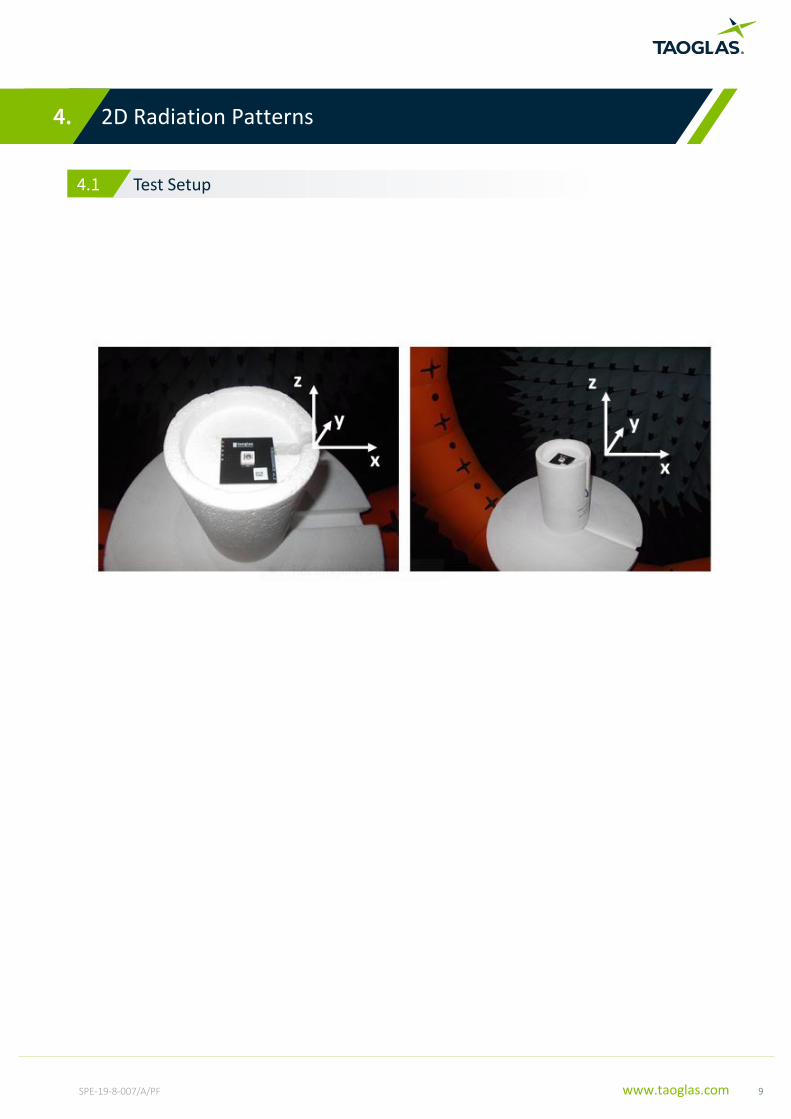
4.1 Test Setup
4. 2D Radiation Patterns
4. Antenna Radiation Patterns
4. Antenna Radiation Patterns
4. Antenna Radiation Patterns
4. Antenna Radiation Patterns
4. Antenna Radiation Patterns
4. Antenna Radiation Patterns
4. Antenna Radiation Patterns

10 SPE-19-8-007/A/PF www.taoglas.com
XY Plane XZ Plane
X Z
YZ Plane
Z
Y X

11 SPE-19-8-007/A/PF www.taoglas.com
5.1 5900MHz
5. 3D Radiation Patterns
4. Antenna Radiation Patterns
4. Antenna Radiation Patterns
4. Antenna Radiation Patterns
4. Antenna Radiation Patterns
4. Antenna Radiation Patterns
4. Antenna Radiation Patterns
4. Antenna Radiation Patterns
dBi

12 SPE-19-8-007/A/PF www.taoglas.com
6.1 LNA Gain and Noise Figure (Active Antenna)
S21 Narrowband Plot
S21 Wideband Plot
6. Active Circuit Characteristics
6. Packaging5. Mechanical Drawing
6. Packaging
7. Application Note6. Packaging5. Mechanical
Drawing
6. Packaging5. Mechanical Drawing
6. Packaging
7. Application Note6. Packaging
7. Application Note
7. Application Note6. Packaging
7. Application Note6. Packaging5. Mechanical
Drawing
6. Packaging5. Mechanical Drawing

13 SPE-19-8-007/A/PF www.taoglas.com
6.2 PA Gain (Active Antenna)
S21 Narrowband Plot
S21 Wideband Plot

14 SPE-19-8-007/A/PF www.taoglas.com
7. Mechanical Drawing (Unit: mm)
6. Packaging5. Mechanical Drawing
6. Packaging
7. Application Note6. Packaging5. Mechanical
Drawing
6. Packaging5. Mechanical Drawing
6. Packaging
7. Application Note6. Packaging
7. Application Note
7. Application Note6. Packaging
7. Application Note6. Packaging5. Mechanical
Drawing
6. Packaging5. Mechanical Drawing

15 SPE-19-8-007/A/PF www.taoglas.com
7.3 Top Solder Mask (Unit: mm)
7.4 Composite Diagram (Unit: mm)

16 SPE-19-8-007/A/PF www.taoglas.com
8. Packaging
7. Application Note
7. Application Note
7. Application Note
7. Application Note
7. Application Note
7. Application Note
7. Application Note

17 SPE-19-8-007/A/PF www.taoglas.com
www.taoglas.com
www.taoglas.com
www.taoglas.com
www.taoglas.com
www.taoglas.com
www.taoglas.com
www.taoglas.com
www.taoglas.com