adaptive building intelligence built on the open services...
TRANSCRIPT

diploma thesis
Adaptive Building Intelligencebuilt on
the Open Services Gateway initiative
Simon Gassmann Patrick Brunner<[email protected]> <[email protected]>
AdvisorsProf. Dr. Rodney Douglas, Institute of Neuroinformatics, ETH/University Zurich
Prof. Dr. Josef Joller, University of Applied Sciences Rapperswil
A cooperation between
Computer Science Department Institute of Neuroinformatics
University of Applied Science Rapperswil University and ETH Zurich
Oberseestrasse 10 Winterthurstrasse 190
8640 Rapperswil, Switzerland 8057 Zurich, Switzerland
http://www.hsr.ch http://www.ini.unizh.ch
May 18, 2005
Typeset by LATEX

OSGi ABI
Prof Dr Josef M Joller (supervisor)
This diploma thesis is a first step in a new ABI direction: the use of well defined services built on top ofa framework (OSGi). Service oriented architectures proved to be very powerful in recent years and the ITworld is still exploring the full potential of this new paradigm.
The delegation of tasks to dedicated services is probably a very natural concept, as can be seen in biologicalsystems; but as it turns out, it also allows the developer to easily expand the system and include morefunctionality or new services and to loosely couple system components.
This diploma thesis opens a whole new ’universe’ we will have to explore in forthcoming term projects andfurther research projects:
• voice driven devices
• mobile devices integration
• fancier graphical representations of the system state
• a more active communication between the user and the system
• and many more exciting things
Several results presented in this diploma thesis give some hints in which direction we will have to make thesystem more ’autonomic’ - self-healing and fault tolerant and more realistic.
The short diploma thesis time frame did not allow to go into too many details. But I believe it points inthe right direction. Some results seem to justify the decision to start ABI from scratch using new and quitedifferent ideas than in the ’old’ ABI.
I look forward to new exciting work and projects and hope both (now ex-) students will have some excitingprojects in their future work life as well. I wish you all the best!
ii

iii
Abstract
Nowadays many modern buildings are equipped with a huge variety of sensors and actors. At the Insti-tute of Neuroinformatics in Zurich a framework for sophisticated controlling of such devices was developed- the Adaptive Building Intelligence System. To improve further extension of the framework a redesign isneeded. The main goal of this diploma thesis is implementing a new software, which uses the well knownOSGi Framework. Stability, reliability, extensibility are keywords for this work. The OSGi Framework pro-vides elaborate concepts that are fully used within the new system.
Additionally, we demonstrate a concept of replaying data using a database connection. This is usefulwhenever new learning algorithm should take over the control of a building. Since it allows deep testingrather than online tests which usually get annoying for inhabitants.
Extensibility is greatly ensured by the OSGi Framework. We introduce an abstract bus model enablingeasy integration of new devices on the fly. Even plug and play mechanism are supported. Moreover, networkavailability is tracked by a general monitoring unit, increasing the overall reliability.
Finally, we present a new learning approach by using goal directed reinforcement learning. This fits perfectlyfor the ambient brightness task needed in adaptive building intelligence. Further concepts are shown in thevery last section describing future elements.
diploma thesis, March 2005

Table of Contents
I Introduction, learning and controlling 1
1 Introduction 2
1.1 Overview . . . . . . . . . . . . . . . . . . . . . . . . . . . . . . . . . . . . . . . . . . . . . . . 2
1.2 This document structure . . . . . . . . . . . . . . . . . . . . . . . . . . . . . . . . . . . . . . . 3
1.3 Related work . . . . . . . . . . . . . . . . . . . . . . . . . . . . . . . . . . . . . . . . . . . . . 3
1.4 Acknowledgments . . . . . . . . . . . . . . . . . . . . . . . . . . . . . . . . . . . . . . . . . . . 3
2 Learning 4
2.1 Reinforcement learning . . . . . . . . . . . . . . . . . . . . . . . . . . . . . . . . . . . . . . . . 4
2.1.1 Reinforcement learning definitions . . . . . . . . . . . . . . . . . . . . . . . . . . . . . 5
2.1.2 R-learning for undiscounted continuing tasks . . . . . . . . . . . . . . . . . . . . . . . 6
2.1.3 R-learning algorithm . . . . . . . . . . . . . . . . . . . . . . . . . . . . . . . . . . . . . 7
2.2 Integration of the r-learning algorithm into building intelligence . . . . . . . . . . . . . . . . . 7
2.2.1 Adapted r-learning algorithm for this project . . . . . . . . . . . . . . . . . . . . . . . 7
2.2.2 Testing the adapted r-learning algorithm for this project . . . . . . . . . . . . . . . . . 10
2.2.3 Punishment for user interactions integrated in the r-learning algorithm . . . . . . . . . 13
2.2.4 Long and short term memory using the r-learning algorithm . . . . . . . . . . . . . . . 13
3 Controlling 14
3.1 Area control of the daylight . . . . . . . . . . . . . . . . . . . . . . . . . . . . . . . . . . . . . 14
3.2 Fuzzy control of the daylight . . . . . . . . . . . . . . . . . . . . . . . . . . . . . . . . . . . . 15
iv

TABLE OF CONTENTS v
II Architecture, Design and Implementation 16
4 Architecture 17
4.1 System components overview . . . . . . . . . . . . . . . . . . . . . . . . . . . . . . . . . . . . 17
4.2 The OSGi Framework . . . . . . . . . . . . . . . . . . . . . . . . . . . . . . . . . . . . . . . . 19
4.3 The ABI System . . . . . . . . . . . . . . . . . . . . . . . . . . . . . . . . . . . . . . . . . . . 21
4.3.1 Infrastructure . . . . . . . . . . . . . . . . . . . . . . . . . . . . . . . . . . . . . . . . . 21
4.3.2 Learning and controlling . . . . . . . . . . . . . . . . . . . . . . . . . . . . . . . . . . . 22
4.4 Other software, and software libraries . . . . . . . . . . . . . . . . . . . . . . . . . . . . . . . 23
4.4.1 MySQL database . . . . . . . . . . . . . . . . . . . . . . . . . . . . . . . . . . . . . . . 23
4.4.2 Jive messenger server . . . . . . . . . . . . . . . . . . . . . . . . . . . . . . . . . . . . 23
4.4.3 Fuzzy Library . . . . . . . . . . . . . . . . . . . . . . . . . . . . . . . . . . . . . . . . . 24
5 Design 25
5.1 ABI core . . . . . . . . . . . . . . . . . . . . . . . . . . . . . . . . . . . . . . . . . . . . . . . . 25
5.1.1 Bus Category . . . . . . . . . . . . . . . . . . . . . . . . . . . . . . . . . . . . . . . . . 25
5.1.2 ABI Bus Service . . . . . . . . . . . . . . . . . . . . . . . . . . . . . . . . . . . . . . . 26
5.1.3 ABI Base Device . . . . . . . . . . . . . . . . . . . . . . . . . . . . . . . . . . . . . . . 26
5.1.4 ABI Log Service . . . . . . . . . . . . . . . . . . . . . . . . . . . . . . . . . . . . . . . 27
5.1.5 Building automation sensors and effectors . . . . . . . . . . . . . . . . . . . . . . . . . 27
5.1.6 Virtual devices services . . . . . . . . . . . . . . . . . . . . . . . . . . . . . . . . . . . 28
5.2 ABI netmonitor . . . . . . . . . . . . . . . . . . . . . . . . . . . . . . . . . . . . . . . . . . . . 29
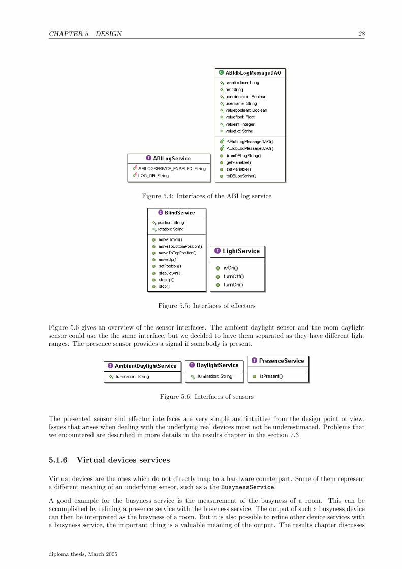
5.3 Dependencies between the ABI bundles . . . . . . . . . . . . . . . . . . . . . . . . . . . . . . 29
5.4 Device - driver concept . . . . . . . . . . . . . . . . . . . . . . . . . . . . . . . . . . . . . . . . 31
5.5 Producer - wire - consumer concept . . . . . . . . . . . . . . . . . . . . . . . . . . . . . . . . . 31
5.6 Asynchronous parts . . . . . . . . . . . . . . . . . . . . . . . . . . . . . . . . . . . . . . . . . 32
6 Implementation 33
6.1 Wireadmin service . . . . . . . . . . . . . . . . . . . . . . . . . . . . . . . . . . . . . . . . . . 33
6.2 Lon bus . . . . . . . . . . . . . . . . . . . . . . . . . . . . . . . . . . . . . . . . . . . . . . . . 34
6.2.1 Detection of manually switched lights . . . . . . . . . . . . . . . . . . . . . . . . . . . 34
diploma thesis, March 2005

TABLE OF CONTENTS vi
6.2.2 Register Lon devices as services upon startup . . . . . . . . . . . . . . . . . . . . . . 34
6.3 Messenger bus . . . . . . . . . . . . . . . . . . . . . . . . . . . . . . . . . . . . . . . . . . . . 35
6.4 Fault Tolerance, Stability and Recovery . . . . . . . . . . . . . . . . . . . . . . . . . . . . . . 35
6.4.1 Netmonitor . . . . . . . . . . . . . . . . . . . . . . . . . . . . . . . . . . . . . . . . . . 36
III Results 37
7 Results and Discussion 38
7.1 Data interpretation . . . . . . . . . . . . . . . . . . . . . . . . . . . . . . . . . . . . . . . . . . 38
7.1.1 Weather condition influence the daylight . . . . . . . . . . . . . . . . . . . . . . . . . . 39
7.1.2 Daylight . . . . . . . . . . . . . . . . . . . . . . . . . . . . . . . . . . . . . . . . . . . . 39
7.2 Virtual devices . . . . . . . . . . . . . . . . . . . . . . . . . . . . . . . . . . . . . . . . . . . . 39
7.2.1 Busyness service and smoothed presence service . . . . . . . . . . . . . . . . . . . . . . 42
7.2.2 Messenger . . . . . . . . . . . . . . . . . . . . . . . . . . . . . . . . . . . . . . . . . . . 42
7.2.3 Fuzzified daytime device . . . . . . . . . . . . . . . . . . . . . . . . . . . . . . . . . . . 42
7.3 Hardware issues . . . . . . . . . . . . . . . . . . . . . . . . . . . . . . . . . . . . . . . . . . . . 44
7.3.1 Blind device . . . . . . . . . . . . . . . . . . . . . . . . . . . . . . . . . . . . . . . . . 44
7.3.2 Daylight device . . . . . . . . . . . . . . . . . . . . . . . . . . . . . . . . . . . . . . . 44
7.3.3 Presence device . . . . . . . . . . . . . . . . . . . . . . . . . . . . . . . . . . . . . . . 48
7.3.4 LNS Server setup . . . . . . . . . . . . . . . . . . . . . . . . . . . . . . . . . . . . . . . 48
7.3.5 Conclusion . . . . . . . . . . . . . . . . . . . . . . . . . . . . . . . . . . . . . . . . . . 48
7.4 Detecting user interaction . . . . . . . . . . . . . . . . . . . . . . . . . . . . . . . . . . . . . . 49
7.4.1 Detection of manual switch changes . . . . . . . . . . . . . . . . . . . . . . . . . . . . 49
7.4.2 Software changes . . . . . . . . . . . . . . . . . . . . . . . . . . . . . . . . . . . . . . . 49
7.5 Chatting with devices . . . . . . . . . . . . . . . . . . . . . . . . . . . . . . . . . . . . . . . . 50
7.6 Wireadmin . . . . . . . . . . . . . . . . . . . . . . . . . . . . . . . . . . . . . . . . . . . . . . 50
7.7 Long and short term memories and reinforcement learning . . . . . . . . . . . . . . . . . . . . 50
7.8 Brithness estimation during night . . . . . . . . . . . . . . . . . . . . . . . . . . . . . . . . . . 52
8 Future work 53
8.1 Data interpretations . . . . . . . . . . . . . . . . . . . . . . . . . . . . . . . . . . . . . . . . . 53
diploma thesis, March 2005
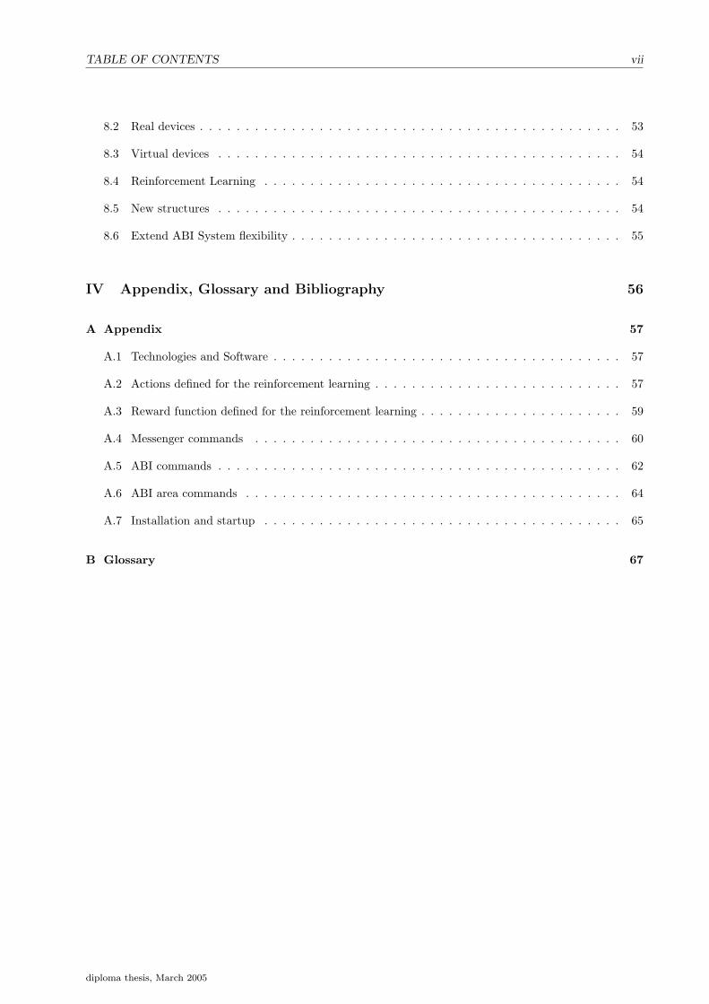
TABLE OF CONTENTS vii
8.2 Real devices . . . . . . . . . . . . . . . . . . . . . . . . . . . . . . . . . . . . . . . . . . . . . . 53
8.3 Virtual devices . . . . . . . . . . . . . . . . . . . . . . . . . . . . . . . . . . . . . . . . . . . . 54
8.4 Reinforcement Learning . . . . . . . . . . . . . . . . . . . . . . . . . . . . . . . . . . . . . . . 54
8.5 New structures . . . . . . . . . . . . . . . . . . . . . . . . . . . . . . . . . . . . . . . . . . . . 54
8.6 Extend ABI System flexibility . . . . . . . . . . . . . . . . . . . . . . . . . . . . . . . . . . . . 55
IV Appendix, Glossary and Bibliography 56
A Appendix 57
A.1 Technologies and Software . . . . . . . . . . . . . . . . . . . . . . . . . . . . . . . . . . . . . . 57
A.2 Actions defined for the reinforcement learning . . . . . . . . . . . . . . . . . . . . . . . . . . . 57
A.3 Reward function defined for the reinforcement learning . . . . . . . . . . . . . . . . . . . . . . 59
A.4 Messenger commands . . . . . . . . . . . . . . . . . . . . . . . . . . . . . . . . . . . . . . . . 60
A.5 ABI commands . . . . . . . . . . . . . . . . . . . . . . . . . . . . . . . . . . . . . . . . . . . . 62
A.6 ABI area commands . . . . . . . . . . . . . . . . . . . . . . . . . . . . . . . . . . . . . . . . . 64
A.7 Installation and startup . . . . . . . . . . . . . . . . . . . . . . . . . . . . . . . . . . . . . . . 65
B Glossary 67
diploma thesis, March 2005

List of Figures
2.1 Service and environment interaction . . . . . . . . . . . . . . . . . . . . . . . . . . . . . . . . 5
2.2 State transition within each row . . . . . . . . . . . . . . . . . . . . . . . . . . . . . . . . . . 8
2.3 State transition within each column . . . . . . . . . . . . . . . . . . . . . . . . . . . . . . . . 8
2.4 States and actions defined for the r-learning algorithm . . . . . . . . . . . . . . . . . . . . . . 9
2.5 Action: daylight wait from state (1,0,0) to (2,0,0). Action at = (st = (1, 0, 0), st+1 = (2, 0, 0))converges with increasing number of matches (numberofmatches >= 50). . . . . . . . . . . . 11
2.6 Action: daylight wait from state (2,0,0) to (1,0,0). Action at = (st = (2, 0, 0), st+1 = (1, 0, 0))converges with increasing number of matches (numberofmatches >= 50). . . . . . . . . . . . 11
2.7 Action: presence change wait from state (1,0,0) to (1,1,0). Action at = (st = (1, 0, 0), st+1 =(1, 1, 0)) converges with increasing number of matches (numberofmatches >= 600). . . . . . 12
2.8 Action: turn light on from state (1,1,0) to (1,1,1). Action at = (st = (1, 1, 0), st+1 = (1, 1, 1))converges with increasing number of matches (numberofmatches >= 300). . . . . . . . . . . 12
3.1 Area controlling . . . . . . . . . . . . . . . . . . . . . . . . . . . . . . . . . . . . . . . . . . . . 14
3.2 Fuzzy control circuit . . . . . . . . . . . . . . . . . . . . . . . . . . . . . . . . . . . . . . . . . 15
4.1 System components overview . . . . . . . . . . . . . . . . . . . . . . . . . . . . . . . . . . . . 18
4.2 bundle states . . . . . . . . . . . . . . . . . . . . . . . . . . . . . . . . . . . . . . . . . . . . . 20
4.3 Overview of the ABI base . . . . . . . . . . . . . . . . . . . . . . . . . . . . . . . . . . . . . . 22
4.4 Overview of the ABI application . . . . . . . . . . . . . . . . . . . . . . . . . . . . . . . . . . 24
5.1 Interface bus category . . . . . . . . . . . . . . . . . . . . . . . . . . . . . . . . . . . . . . . . 26
5.2 Interface ABI bus service . . . . . . . . . . . . . . . . . . . . . . . . . . . . . . . . . . . . . . 27
5.3 Interface ABI base device . . . . . . . . . . . . . . . . . . . . . . . . . . . . . . . . . . . . . . 27
5.4 Interfaces of the ABI log service . . . . . . . . . . . . . . . . . . . . . . . . . . . . . . . . . . . 28
5.5 Interfaces of effectors . . . . . . . . . . . . . . . . . . . . . . . . . . . . . . . . . . . . . . . . . 28
viii

LIST OF FIGURES ix
5.6 Interfaces of sensors . . . . . . . . . . . . . . . . . . . . . . . . . . . . . . . . . . . . . . . . . 28
5.7 Interfaces of virtual devices . . . . . . . . . . . . . . . . . . . . . . . . . . . . . . . . . . . . . 29
5.8 Interfaces of ABI netmonitor . . . . . . . . . . . . . . . . . . . . . . . . . . . . . . . . . . . . 29
5.9 Dependencies of the main ABI bundles . . . . . . . . . . . . . . . . . . . . . . . . . . . . . . . 30
5.10 Overview of the different system updates . . . . . . . . . . . . . . . . . . . . . . . . . . . . . . 32
7.1 Neuroinformatic Institute situation on the campus . . . . . . . . . . . . . . . . . . . . . . . . 38
7.2 Building 55, floor G, Institute of Neuroinformatics . . . . . . . . . . . . . . . . . . . . . . . . 39
7.3 Weather influence on the daylight recorded on the 20th and 29th April 2005 . . . . . . . . . . 39
7.4 Membership functions of the fuzzy daylight linguistic variable . . . . . . . . . . . . . . . . . . 40
7.5 Mapping from hardware to software and then to virtual device services. . . . . . . . . . . . . 41
7.6 Presence, smoothed presence and busyness service . . . . . . . . . . . . . . . . . . . . . . . . 42
7.7 Virtual busyness service, recording time approximately 1 hour, room 55.G.28. . . . . . . . . . 43
7.8 Membership functions for the fuzzified daytime device.. . . . . . . . . . . . . . . . . . . . . . 44
7.9 Daylight recorded on 19th April to 29th April 2005 in room 55.G.74 . . . . . . . . . . . . . . . 45
7.10 Daylight recorded on 1st April in room 55.G.74 between 7:30 a.m. - 8:15 a.m. . . . . . . . . 46
7.11 Daylight recorded on 1st April in room 55.G.75B between 5:50 a.m. - 9:07 p.m. . . . . . . . . 47
7.12 Daylight recorded on 1st April in room 55.G.75 between 5:50 a.m. - 9:07 p.m. . . . . . . . . 47
7.13 Current LNS Server, Lon gateway and host network setup. . . . . . . . . . . . . . . . . . . . 48
7.14 Improved LNS Server, Lon gateway and host network setup. . . . . . . . . . . . . . . . . . . 49
7.15 Long and short term memory overview . . . . . . . . . . . . . . . . . . . . . . . . . . . . . . . 51
7.16 Long term memory q-table recorded in room 55.G.84 from 2nd May - 4th Mai 2005. . . . . . 51
7.17 Short term memory q-table recorded in room 55.G.84 from 2nd May - 4th Mai 2005. . . . . . 51
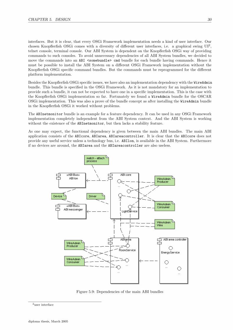
A.1 Type ’help’ for all available commands. . . . . . . . . . . . . . . . . . . . . . . . . . . . . . . 61
A.2 Messenger help dialog . . . . . . . . . . . . . . . . . . . . . . . . . . . . . . . . . . . . . . . . 61
A.3 Messenger main window . . . . . . . . . . . . . . . . . . . . . . . . . . . . . . . . . . . . . . . 61
diploma thesis, March 2005

List of Tables
2.1 States used for the r-learning algorithm . . . . . . . . . . . . . . . . . . . . . . . . . . . . . . 9
4.1 Example device service registration . . . . . . . . . . . . . . . . . . . . . . . . . . . . . . . . . 23
7.1 Weather information provided by MeteoNews Zurich . . . . . . . . . . . . . . . . . . . . . . . 40
7.2 Toggling of daylight values in room 55.G.74 . . . . . . . . . . . . . . . . . . . . . . . . . . . . 45
A.1 States used for the r-learning algorithm . . . . . . . . . . . . . . . . . . . . . . . . . . . . . . 58
A.2 Rewards used in states s[1,0,0], s[2,0,0], s[3,0,0], s[1,1,0], s[2,1,0], s[3,1,0], s[1,0,1], s[2,0,1] and s[3,0,1]
for the r-learning algorithm . . . . . . . . . . . . . . . . . . . . . . . . . . . . . . . . . . . . . 59
A.3 Rewards used in states s[3,0,1],s[1,1,1], s[2,1,1] and s[3,1,1] for the r-learning algorithm . . . . . . 60
B.1 Glossary. . . . . . . . . . . . . . . . . . . . . . . . . . . . . . . . . . . . . . . . . . . . . . . . . 67
x

Part I
Introduction, learning and controlling
1

Chapter 1
Introduction
1.1 Overview
The adaptive building intelligence system (ABI System) was developed during previous term works as wellas diploma thesis. Modern buildings can actively support and assist their inhabitants. The ABI System wasdesigned to learn dynamic environment changes. Different approaches for learning have been introduced. Amajor improvement in the learning task was done by the previous work [TZ04] where a long and short termmemory were presented.
The main goal of the diploma thesis was to develop a new stable version of the existing ABI System. Inour previous term work [BG04] we answered the question how the ABI System can be integrated in theOSGi Framework. We showed the advantages of using a well-known framework, which has the ability ofadapting to dynamic changes. During the evaluation in the term work we also encountered several problems.Complexity of dynamic programming is a drawback and very time consuming. All the same it leads to aeasy extendable system. The OSGi Framework turned out to be fairly complicated to understand. In thisdiploma thesis we built the ABI System from scratch, not using any components from the previous releases.Only the abstract bus concept developed in our term work was taken into consideration.Unlike the term work, which compromises a proof of concept, we implemented here a fully working new ABISystem based on the OSGi Framework [Ini03]. We also solved several major insufficiencies of the old ABISystem. It lacked from occurring exceptions during run-time, which are believed coming from the underlyingLNS Server. To avoid problems of this kind we investigated Londevice specifications and kept strictly togiven instructions and recommendations of [Lon].Moreover a database connection was implemented as a first step to ensure having descent data used fordata mining in the results section and for learning tasks. A concept of replaying situations from the database is also a part of this diploma thesis, which could play a key role in future works. Since new learningalgorithm can be easily tested on recorded data. The OSGi Framework is designed for dynamical changesof any service. Thus the implemented software is a starting point for any following projects.Learning plays a major role in building intelligence. We therefore implemented a new learning approach inthis diploma thesis. A reinforcement learning algorithm which was adapted to the fulfill building intelligencehas been used. Another main task was implementing recovery mechanisms. To achieve that goal many newrecovery concepts are introduced within this work.Apart from hardware devices also the concept of virtual software devices is shown. This is particularimportant if collecting hardware events and upon them producing new output. Implemention of new devicetypes which did not exists within the old ABI System is done to have more input for the learning task, i.e.virtual devices.
2

1.2. THIS DOCUMENT STRUCTURE 3
1.2 This document structure
This diploma thesis contains the following parts and main sections. We start with a short introductionand then give an overview of reinforcement learning. In the controlling section we present a fuzzy controlcircuit and explain the control unit used. Architecture, design and implementation sections describe thenew built ABI System. Finally the results are summarized and discussed in the last section. Project setup,administrative commands, messenger commands, reinforcement implementation details and installationsinstructions are presented in the appendix section.
1. Introduction
2. Learning
3. Controlling
4. Architecture, design and implementation
5. Results
6. Appendix
1.3 Related work
In this section the key parts of all the related works is presented. It is by no means a complete comparison ofthe previous related term works and diploma thesis. In the following list we describe the different approaches.
• Ueli Rutishauser and Alain Schaefer → Learning without additional user input, online learning algo-rithm, learning a maximal structure, fuzzy rule base with anytime learning algorithm and no dynamicstructure detection.
• Jonas Trindler and Raphael Zwiker → Short and long term memory, parallel architecture of the controlunit and multi agent framework.
1.4 Acknowledgments
We would like to thank Raphael Zwiker for many crucial hints and illuminating discussions - Hanno Gassmannfor reading the manuscript. We would also like to acknowledge Matthias Saenger for the weather informationprovided 7.1 and reading the manuscript. Finally we would like to thank Robert Brunner for giving helpfulinformation about brightness calculation for the light devices 7.8.
diploma thesis, March 2005

Chapter 2
Learning
In this chapter we describe the reinforcement learning algorithm we used in our project. First a shortoverview is given and then we explain how we implemented our learning approach. Further informationabout reinforcement learning or machine learning is provided by [RSS98] and [Mit97].
2.1 Reinforcement learning
In this section we first give a short introduction to reinforcement learning. Subsequently the elements ofreinforcement learning are described.
In general, reinforcement learning is a computational approach to understand goal-directed learning anddecision-making. It uses states, actions and rewards to define the interaction between a learning serviceand its environment. A key feature of reinforcement learning are explicit goals. The learner is not toldwhich actions to take, but must discover itself which action yield the most reward by trying them. Sincean action can influence current situations as well as future situations it is important to take both situationsinto consideration while rewarding an action. This leads to two characteristics:
1. trial and error search
2. delayed reward, a reward that is given after an action has been executed
A reinforcement learning system consists of a policy, a reward function, a value function and optionally amodel of the environment. These elements are now briefly introduced.
A policy defines the behaviour of a learning service at a given time. It basically maps from perceived statesof the environment to actions. This means whenever a specific state is perceived an action follows (state -action pair). In simple cases the policy may be a lookup table. More complex cases might need extensivecomputation such as a search process.
A reward function defines the goal in reinforcement learning. It maps the previously explained policy (state- action pair) to a single number, the so called reward. An objective of the reinforcement learning serviceshould be maximizing the total received rewards. In other terms the reward function defines the good andbad events for the learning service.
In contrast to the reward function which indicates somehow what is good in an immediate sense, a valuefunction specifies what is good in the long run. The value function defines the total amount of reward alearning service can expect to accumulate over time when starting in a specific state.
The last mentioned element is the model. Models are used for planning. A model can for example predictthe resultant next state and therefore also the next reward.
4

2.1. REINFORCEMENT LEARNING 5
Figure 2.1: Service and environment interaction
As described in figure 2.1 the reinforcement service interacts continually with the environment by selectingactions and receiving rewards for that performed action. Those actions present then new situations (so calledstates) to the reinforcement learning services. The rewards received are special numerical values that thelearning service tries to maximize over time. A complete specification of an environment such as learningservice, states, actions, rewards and environment defines a task.
2.1.1 Reinforcement learning definitions
We give here the common definitions of reinforcement learning, as well as a description of the activity chainin figure 2.1.
Time steps are defined as:t = 0, 1, 2, 3, ... in a continuing task: t →∞ (2.1)
Environment states are defined as:
st ∈ S whereas S is the set of possible states (2.2)
Actions are defined as:
at ∈ A (st) where A (st) is the set of possible actions available in state st (2.3)
Numerical reward is defined as:rt+1 ∈ < (2.4)
Estimated action values are defined as:
V (st+1) = V (st) + α [V (st+1)− V (st)] where α is a step sizeparameter (2.5)
Estimated action-values are defined as:
Qt (a) =r1 + r2 + r3 + ... + rka
ka(2.6)
To specify more clearly here the t-th play of a action a has been chosen ka times prior to t, rewards receivedare then r1, r2, ..., rka
.
At each time step t, the learning service takes an action at. As a consequence of its action, the learningservice receives a numerical reward rt+1 ∈ R and is then in a new state st+1. To choose an action out of allpossible actions A (st) a policy πt is used.
diploma thesis, March 2005

CHAPTER 2. LEARNING 6
A policy is defined as:
πt where πt (s, a) is the probability that at = a if st = s (2.7)
A common policy used is the ε-policy. Most of the time this policy chooses an action that has a maximalaction value. That means it takes the action with the highest reward so far calculated. With a probabilityof ε it chooses an action at random. It follows that all nongreedy actions are given the minimal probabilityas follows:
ε
|A (s) |(2.8)
Further all greedy actions are given the probability:
1− ε +ε
|A (s) |(2.9)
Such a policy ensures that actions are taken that have a high action value calculated so far (exploit) andfrom time to time with a probability of ε it chooses a new action (explore). It balances the learning taskbetween exploit and explore actions. This makes sense since it is important to see if there are actions thatmight also have reasonable rewards that we don’t know so far.
2.1.2 R-learning for undiscounted continuing tasks
In cases the service-environment interaction does not break naturally into identifiable episodes, the learningis called a continuing task. In such cases it is not possible to calculate the return Rt = rt+1 +rt+2 +rt+3 + ...,as t →∞. A common approach is then using discounts on the return R as follows:
Rt = rt+1 + γrt+2 + γ2rt+3 + ... =∞∑
k=0
γkrt+k+1 (2.10)
R-learning is not using such a discount rate of the return value. One tries to obtain the maximum rewardper time step. This time step must refer to fixed intervals of real time - they can refer to arbitrary successivestage of decisions making. The value functions for a policy π are defined relative to the average expectedreward (per time step):
pπ = limn→∞
1n
n∑t=1
Eπ [rt] (2.11)
Assumption: the process is ergodic, meaning there exists an nonzero probability of reaching any state fromany other. Thus pπ does not depend on the starting state. The value of a state is defined as:
V π (s) =∞∑
k=1
Eπ [rt+k − pπ|st = s] (2.12)
The value of an state-action pair is defined as:
Qπ (s) =∞∑
k=1
Eπ [rt+k − pπ|st = s, at = a] (2.13)
These values are called relative values since they are relative to the average reward under a chosen policy. R-learning is a Temporal-Difference learning (TD) approach, since it uses differences V (st+1)−V (st) betweenestimates at two different times. In the R-learning algorithm this is done by calculating differences betweenQ (st+1, at+1)− Q (st, at).
diploma thesis, March 2005

2.2. INTEGRATION OF THE R-LEARNING ALGORITHM INTO BUILDING INTELLIGENCE 7
2.1.3 R-learning algorithm
The r-learning algorithm is defined as follows:
Initialze p and Q(s,a) for all s,a
Repeat forever:
1. s <- current state2. Choose action a in s using behaviour policy (e-greedy)3. Take action a, observe r, s’4. Q(s,a) = Q(s,a) + a [r-p+max{Q(s’,a’),a’} - Q(s,a)]5. If Q(s,a) = max{Q(s,a),a} then:
p = p + b[r-p+max{Q(s’,a’),a’}-max{Q(s,a),a}]
whereas max{Q(..),a} means seeking for (s,a)-pairs that maximize the Q(..) value.
Parameters a := α and b := β are step size parameters.These step size parameters have only an influence onthe Q(s,a) values and how they are taken into consideration when a state change is performed in terms ofst → st+1 for a specific action at.
2.2 Integration of the r-learning algorithm into building intelli-gence
Depending on hardware devices many states can be possible. To cut down the amount of states and thereforethe computation power used, we decided to use the following devices that define our states:
1. daylight, depends on light given by the environment (sun and electrical light).
2. presence, indicates the attendance of a person.
3. light, electrical light, can be turned on and off.
For further information see also 6. We give here just a general overview.
2.2.1 Adapted r-learning algorithm for this project
We first describe our approach by explaining what states we defined for the learning service. We definedstates as follows:
si = [x, y, z] (2.14)
x =
1 daylight range 12 daylight range 23 daylight range 3
y ={
0 somebody is present1 nobody is present
z ={
0 light is off1 light is on
diploma thesis, March 2005

CHAPTER 2. LEARNING 8
To make things clear we give here an overview of all states in table 2.1. First we introduce the state transitionsoccurring within each row and each column, then the states overview is given, omitting the former introducedtransitions. The figure 2.2 shows the row transitions, whereas figure 2.3 shows column transitions. A rowis arranged in a way that only the daylight changes are possible, thus the transitions are restricted to waitfor these daylight changes. Column transitions described in figure 2.3 though show changes that occur onthe presence level. One must bear in mind that in every state there is also the implicit transition to itselfpossible, the wait self transition. Transitions for the lights are showed in figure 2.4 excluding the abovementioned daylight, presence and wait self transitions.
Figure 2.2: State transition within each row
Figure 2.3: State transition within each column
Actions at are defined as at = (st, st+1). The problem we encountered with the r-learning algorithm wasthat we have only a few actions we can really take such as, turning lights on or off. All other input comesdirectly from the environment i.e. daylight changes. That means we can not change the daylight value bytaking an action. This leads us to change the algorithm and allow sudden state changes invoked by theenvironment to take place. In such cases we don’t reward the action at all, except the wait actions weintroduced. Wait actions are different from actions that have an impact on the environment. Generally theyare used to learn also to wait for a state change invoked by the environment. For example if we wait for adaylight change at = (st = (1, 0, 0), st+1 = (2, 0, 0)) in a certain state st = (1, 0, 0) and the daylight changesto state st+1 = (2, 0, 0) invoked by the environment results in a reward given. In other situations where theaction chosen does not match the state we suddenly encounter from the environment, we simply adjust ouralgorithm and bring it to the appropriate state. For example the current state is st(1, 0, 0). Let us assumethe action we choose to perform is at = (st = (1, 0, 0), st+1 = (1, 1, 0)). Unfortunately the next state invokedby the environment is st(2, 0, 0). In this situation we do not give rewards at all, since the action does notmatch. We believe this must work as the r-learning algorithm is not depending on its starting state.To simplify the algorithm’s complexity we also decided to have only a small amount of states and actionsare not allowed being built on run time (for an overview of states and actions see table 2.1 and figure A.1).In addition states and actions have been chosen to give a simple but effective learning for our ambient roomlearning task.
diploma thesis, March 2005

2.2. INTEGRATION OF THE R-LEARNING ALGORITHM INTO BUILDING INTELLIGENCE 9
Figure 2.4: States and actions defined for the r-learning algorithm
State daylight presence lights1 = [1, 0, 0] daylight is in range 1 nobody is present the light is offs2 = [2, 0, 0] daylight is in range 2 nobody is present the light is offs3 = [3, 0, 0] daylight is in range 3 nobody is present the light is offs4 = [1, 1, 0] daylight is in range 1 somebody is present the light is offs5 = [2, 1, 0] daylight is in range 2 somebody is present the light is offs6 = [3, 1, 0] daylight is in range 3 somebody is present the light is offs7 = [1, 0, 1] daylight is in range 1 nobody is present the light is ons8 = [2, 0, 1] daylight is in range 2 nobody is present the light is ons9 = [3, 0, 1] daylight is in range 3 nobody is present the light is ons10 = [1, 1, 1] daylight is in range 1 somebody is present the light is ons11 = [2, 1, 1] daylight is in range 2 somebody is present the light is ons12 = [3, 1, 1] daylight is in range 3 somebody is present the light is on
Table 2.1: States used for the r-learning algorithm
diploma thesis, March 2005

CHAPTER 2. LEARNING 10
2.2.2 Testing the adapted r-learning algorithm for this project
We first developed a test environment to ensure our slightly adapted r-learning algorithm works as expectedand fulfills the given requirements. We have chosen a random starting state st=random(1−12) = s1 and thenwe chose one of the possible actions in this state randomly a(s1, st=random(1−12)=s2∗), whereas this actionwas only rewarded if the following state st=random(1−12) = s2 was the one predicted previously s2 = s2∗.This was repeated for 500’000 times. It is obvious that matching a state predicted by an action is not verylikely thus out of these 500’000 trials only 41’672 rewards were given. All Q(s, a) have been initialized withzero.
The following example helps understanding the test set up.
1. choose a starting state randomly → sstart = (1, 0, 0)
2. actions possible in state sstart are:
• awaitself (100, 100)
• awaitdaylight(100, 200)
• awaitdaylight(100, 300)
• apresencechangewait(100, 110)
3. choose randomly an action → awaitdaylight(100, 200).
4. repeat forever (in this example only one cycle is showed):
• choose a next state randomly → snext = (2, 0, 0)
• if action predicted this as the following state → yes → do reward
• else if check was not successful do not reward
Step size parameters were set to the following values:
• step size parameter α=0.1
• step size parameter β=0.0
• ε-greedy = 0.1
The reward function which denotes reward to matched actions is described in the appendix A.2 and A.3.We chose a reward function that gives always the same reward for a matched action. Some of the results areshown in following figures 2.6, 2.6, 2.7, 2.8. An important fact is that all q-values of a certain state-actionpair converge to a real number. Even though some actions matched more than others, depending on thereward function and the ε-greedy choosing algorithm, it is shown that all q-values converge. As mentionedearlier (2.1.2) this is exactly what we expected since the r-learning algorithm is not depending on its startingstate. Assume that π is the estimation policy, then the action-value Q is an approximation of Qπ. It followsfrom the definition that the average reward p is an approximation of pπ. In this test run we calculated anaverage reward of p = 5.875000000000019.
diploma thesis, March 2005

2.2. INTEGRATION OF THE R-LEARNING ALGORITHM INTO BUILDING INTELLIGENCE 11
Figure 2.5: Action: daylight wait from state (1,0,0) to (2,0,0). Action at = (st = (1, 0, 0), st+1 = (2, 0, 0))converges with increasing number of matches (numberofmatches >= 50).
Figure 2.6: Action: daylight wait from state (2,0,0) to (1,0,0). Action at = (st = (2, 0, 0), st+1 = (1, 0, 0))converges with increasing number of matches (numberofmatches >= 50).
diploma thesis, March 2005

CHAPTER 2. LEARNING 12
Figure 2.7: Action: presence change wait from state (1,0,0) to (1,1,0). Action at = (st = (1, 0, 0), st+1 =(1, 1, 0)) converges with increasing number of matches (numberofmatches >= 600).
Figure 2.8: Action: turn light on from state (1,1,0) to (1,1,1). Action at = (st = (1, 1, 0), st+1 = (1, 1, 1))converges with increasing number of matches (numberofmatches >= 300).
diploma thesis, March 2005

2.2. INTEGRATION OF THE R-LEARNING ALGORITHM INTO BUILDING INTELLIGENCE 13
2.2.3 Punishment for user interactions integrated in the r-learning algorithm
The problem to solve is answering the question how punishment can be integrated into the r-learning algo-rithm. A simple but effective approach is to adapt the static reward function to a dynamic reward function.So far we had for any action at a constant reward value. For example an action aturnlighton(110, 111) ischosen. Then the light in a certain room (area) is turned on, but the user is not satisfied with this decisionand turns the light off immediately. The learning system can detect such user interaction and then adaptits reward for the given action to a smaller value - even negative rewards would be thinkable. To do so adelayed reward has to be implemented, because the reward can only be given correctly if we wait for timeoutand then do the reward. Another approach is to change the calculated Q(s, a) value i.e. to a smaller one.This is a more direct way than the first described idea, since it has a more direct influence on the futureaction chosen.
2.2.4 Long and short term memory using the r-learning algorithm
It makes sense having a short and a long term memory in adaptive building intelligence (see related work[TZ04]). Assume that all Q(s, a) values are stored in a table over a certain time period , e.g. Monday morning.The short term memory could be simulated by saying, all Q(s, a) values experienced and calculated so farrepresent the short term memory. If the time period changes, e.g. to Monday afternoon, a new short termmemory period is evoked. The Q(s, a) calculated for the period Monday morning is then merged into thelong term memory, which could be also a table of Q(s, a) values. Merging can be done by calculating anaverage value for each entry in the table. Decision can then be done by taking into consideration both, theshort and long term memory.
diploma thesis, March 2005

Chapter 3
Controlling
In this section we describe the general controlling mechanism used. Our first approach was using a fuzzycontrol circuit, which turned out as an inadequate solution see 3.2. The second approach is more sophisticatedand works fine, see 3.1 for more details.
3.1 Area control of the daylight
The area room service is responsible for recording the current state given by its connected devices. It thensends the perceived state to the area decision controller unit, which in turn asks each connected sub controllerunits for an action proposal. Based on the received actions it must decide what action to choose and pass thisaction back to the area room service. Ambient controller or energy controller uses reinforcement learning,i.e. also short and long term memories are thinkable. This way of controlling is strongly goal directed.
Figure 3.1: Area controlling
14

3.2. FUZZY CONTROL OF THE DAYLIGHT 15
3.2 Fuzzy control of the daylight
Our first approach was to build a control circuit to achieve a certain luminance in an predefined area.Controlled devices include lights and blinds. We used a fuzzy library for our control circuit. For furtherinformation about fuzzy and the used fuzzy library see [Tra02] and [Fuz]. Figure 3.2 shows the control circuitused.
Figure 3.2: Fuzzy control circuit
The fuzzy control unit is feed with light, blind and daylight input from the process (environment). Basedon the input values it produces then output for the blind and light devices. Generally this worked finecontrolling the daylight in a room, the problem we were faced is that the blinds can get out of sync andreturn false input for the fuzzy control unit. In such cases the system crashes, i.e. results in unexpectedbehaviour. Hardware blind issues are discussed further in section 7.3. We decided not to use the fuzzycontrol circuit for our learning task, since it turned out to be not stable in terms of the wrong behaviour ofthe blind devices.
diploma thesis, March 2005

Part II
Architecture, Design andImplementation
16

Chapter 4
Architecture
This chapter defines the system architecture and its goals. Furthermore we introduce the chosen softwarecomponents. Whenever possible we were searching and integrating high quality components implementinga standard, and released as open source.
We start with an overview of the system components and how they play together. Later in the chapter werefine the descriptions of the different system components. For a better understanding of the ABI Systemsarchitecture we introduce the OSGi Frameworks concept beforehand. Issues, problems and their solutionare discussed in the implementation chapter 6 and the design chapter 5 respectively.
4.1 System components overview
The whole considered system, is a heterogeneous distributed system of hardware and software components.From now on we use the term ABI System for the components designed and implemented by ourself, and alsofor the open source components1 adapted for our needs. The overall goal of the here presented architectureis to provide an open, flexible, and service oriented architecture. We made an effort for a solid base usingstandards2 and applying standard procedures3. Most important, the architecture must meet the AdaptiveBuilding Intelligence task requirements. Roughly speaking, these are:
Bus abstraction: to interconnect different field buses, and virtual buses feeding information into the ABISystem.
Device abstraction: separate the real device from its provided information input, and also to allow virtualdevices without hardware representation.
Collecting data: collect all the raw information by sensing the building and its environment.
Learn from data: extract features, learn patterns from the collected data. Moreover classify a new situa-tion, resulting in a decision for an action to take.
First of all there is a hardware network of sensors and effectors in a building. These are interconnected witha hardware field bus. Typically such an installation is delivered with a software to configure the networkstructure. The problems of such a configuration are stated in the chapter 1. The ABI System starts wherethe static rule configuration ends.
From the above stated it is clear, that there are software components abstracting the hardware in such away that different field bus technologies and different kind of devices can be handled by the ABI System.
1Namely the Wireadmin Service Bundle, and the Fuzzy Library.2Telnet Protocol, SQL, XMPP, XML, URI, LDAP filter string RFC19603procedures as described in the [Ini03], knopflerfish programming documentation, software design and patterns
17

CHAPTER 4. ARCHITECTURE 18
The abstraction is one part, on the other hand, each bus hardware technology requires a specific softwarecomponent to make it accessible from the ABI System. Besides of the hardware abstraction there is alsothe need for a structural abstraction. This structure component should be flexible enough to handle both,static4 and dynamic5 structures. Or at least it should allow the coexistence of dynamic and static structures.Typically, such components have an administrative6 side besides the functionality they provide. Thus thedemand for an administrative component. As with all distributed heterogeneous software system, it is veryimportant to have a central information or log facility. In fact in a system trying to do machine learningit is of most importance to have a possibility to gather, save, and retrieve information in a structured way.From this follows the claim of an information storage component.
The so far enumerated components do not bring in the adaptive building intelligence part, but they are theneeded infrastructure for the machine learning and controlling component.
Our container for the outlined ABI Systems components is the OSGi Framework, a java application container.The key features of the OSGi Framework architecture are introduced in the section 4.2.
Figure 4.1: System components overview
The figure 4.1 serves as a high level overview of the previous described components, whereas the componentshave the names according to the ABI System. The following list matches the components to the names.Bundle is the term for component used in the OSGi Framework environment.
bus and device abstraction The ABIcore Bundle provides an abstract bus and device abstraction foreach sensor and effector.
4Dependencies like building - floor - room5Discovering related sensors and effectors without prior knowledge of a static structure.6Define configurations, showing an internal status, startup, shutdown
diploma thesis, March 2005

4.2. THE OSGI FRAMEWORK 19
bus technology component The ABIlon Bundle is a specific bus technology implementation for connect-ing the ABI System to the LonWorks field bus. It is also responsible for the Lon specific imple-mentations of the sensor and effector devices. The ABImessenger Bundle is the bridge for the ABISystem to the instant messenger server – a Jive Messenger server in our case. Actually it implementsa presence sensor.
structural abstraction The ABIarea Bundle represents the static building - floor - room structure, andfinds devices in a plug and play fashion. Furthermore it coordinates the learning and controlling aspect.
administrative component Instead of having one monolithic administrative component, it is dividedinto the ABIcoreCmd Bundle and the ABIareaCmd Bundle. Each of these bundles is a command-lineproviding administrative bundle for its corresponding service bundle.
central log component The central log component is placed in the ABIcore Bundle as it is seen as corefunctionality.
information storage We decided to use the MySQL database as information storage. But this is notmandatory, as the logged information is written to a file if a database is not available. Although it ishighly recommended to use a database.
learning component The ABIlearning Bundle makes different machine learning approaches accessibleto the ABI System.
controller component The ABIcontrolling Bundle offers controlling mechanisms to the ABI System.
4.2 The OSGi Framework
This section introduces the OSGi Framework as far it is needed to understand the resulting ABI System ar-chitecture. It explains the OSGi Framework terms bundle, service, service reference, and service registrationproperties. The section ends with the OSGi Framework concept of filters.
OSGi stands for Open Service Gateway initiative.
The OSGi Framework is a lightweight framework providing the infrastructure for hot plugging7 softwarecomponents, while the framework is running. It is designed to be stable robust and long running. Theinterested reader can find more details about the framework in our term work [BG04]. Here we focus on thekey features for a better understanding of the whole architecture.
A software component in the OSGi Framework is understood as a bundle providing one or more services.Other software components use the available services to combine and refine them to a new service. Anapplication is viewed as a, more or less, loose coupled collection of services.
The OSGi Framework provides the infrastructure to install, uninstall, update, start and stop bundles. Andthe bundles use the OSGi Framework to register and deregister their services, and also to look up and trackother bundle’s services. One has to bear in mind, that services can appear, disappear and change duringruntime. Each bundle must take care to handle this dynamic aspect correctly.
One can see the OSGi Framework as a registry of services, providing the infrastructure which
• fires events when a bundle is installed, deinstalled, updated, started stopped
• fires events when a service is registered, deregistered, changed.
• helps to look up services with the help of a filter facility
• helps to track services
7plug in and out software components
diploma thesis, March 2005

CHAPTER 4. ARCHITECTURE 20
As the OSGi Framework is a specification only, there exists different implementations - commercial oneson one hand, but also open source ones on the other hand. Besides the core framework, the specificationdescribes in detail useful bundles in the context of gateways8.Our term work [BG04] points out the detailswhy the OSGi Framework is a good choice for the Adaptive Building Intelligence application, and whichdescribed bundles to take as base pillars.
Technically spoken, application units like the ABIcore Bundle, are deployed as bundles. A bundle is aJAR-file9 containing a MANIFEST.MF file10. The manifest describes the contents of the jar file Within theOSGi Framework a bundle has a life cycle as illustrated with the figure 4.2. When a bundle is started it is
Figure 4.2: bundle states
initialized with a bundle context object which serves as interface from the bundle to the OSGi Framework.It allows the bundle to access methods from the framework. And the OSGi Framework uses the bundlecontext for book keeping various things concerning the started bundle.
A closer look on how the OSGi Framework service concept works, is as follows. It is recommended to definean interface describing the services. This interface is exported to the OSGi Framework and imported byother bundles. The bundle providing the service, creates one or more instances of classes implementing thisinterface. It makes this service implementation instances available by registering them within the OSGiFramework under the interface’s fully qualified class name. Other bundles query the OSGi Framework witha filter interface provided by the framework. Applying a filter to the frameworks registry does not return therequested services, instead it returns the descriptive portion of the service - the service reference. A servicereference holds a dictionary describing the requested service. If the description satisfies the needs of therequesting bundle, it can obtain the service through the bundle context and the service reference. Potentiallya service reference can exist without an available service, this case must always be handled appropriate bythe requesting bundle. It is up to service registering bundle to provide a useful set of properties in the serviceregistration.
The service descriptions, or more formally the service registration properties, are mission critical. Thesedescriptions act as the glue between services, and bundles respectively. Viewing an application as a collectionof related services, the registration properties are responsible for relating the services. Thus these propertiesare part of the applications architectural design, or the applications complexity. The service registrationproperties are stored as key - value tuples, whereas key is a string constant and value is any object, or anarray of objects.
Last but not least the OSGi Framework overview is completed with the important filter feature. As theOSGi Framework is mainly a registry for services, along with their service registration properties, it is ofutmost importance to have an easy way to filter for services. The filter syntax string is based on the RFC1960. This RFC defines a representation of LDAP search strings with the following grammar:
8the primary target was the gateway in the broadband connected home.9Java archive file, a zip compressed form of a file structure
10it is a configuration file holding key,value pairs.
diploma thesis, March 2005

4.3. THE ABI SYSTEM 21
filter ::= ´(´ filter-comp ´)´filter-comp ::= and | or | not | itemand ::= ´&´ filter-listor ::= ´|´ filter-listnot ::= ´!´ filterfilter-list ::= filter | filter filter-listitem ::= simple | present | substringsimple ::= attr filter-type valuefilter-type ::= equal | approx | greater | lessequal ::= ´=´approx ::= ´~=´greater ::= ´>=´less ::= ´<=´present ::= attr ´=*´substring ::= attr ´=´ initial any finalinital ::= () | valueany ::= ´*´ star-valuestar-value ::= () | value ´*´ star-valuefinal ::= () | value
The attr is a key in service registration properties and the value the extracted value object. If the valueobject is of type array of objects, or vector, the filter is applied recursively. Also numeric and string objectsare handled according to their types. More details can be found in [Ini03].
4.3 The ABI System
This section covers our ABI Systems architecture within the OSGi Framework. Choosing the OSGi Frame-work as application framework implied breaking down the Adaptive Building Intelligence application intobundles and services. The section cuts also in the two main aspects learning and controlling (4.3.2) andinfrastructure (4.3).
4.3.1 Infrastructure
The infrastructure part has two major responsibilities:
• abstraction of real buses and devices
• collecting information
The figure 4.3 shows the part of the ABI System providing the infrastructure for the Adaptive BuildingIntelligence application.
On one hand the abstraction is achieved by specifying an ABI bus service which describes how a bus isaccessed in the ABI way. On the other hand there are abstractions for the most common devices used in thebuilding automation. For each technology bus we want to connect with the ABI System, we have to providea bundle with the specific bus access technology. In most building automation cases the devices are tightlycoupled with the used bus. Hence the implementation for a bus will also carry the implementations for thedevices. But the architecture does not prescribe to have the bus and device implementations in one bundle.One can argue having the bus and its devices in one bundle helps structuring the software, but we see it asan unnecessary restriction. As it is too specific to field buses. If we extend the ABI System beyond the fieldbus we can take office buses into account. Office bus examples are the Ethernet, or the USB. And it is clearthat there are far more possible devices for these office buses, than we can think of now.
diploma thesis, March 2005

CHAPTER 4. ARCHITECTURE 22
Figure 4.3: Overview of the ABI base
In principle we see the bus as the administrative component to the network of devices. As a consequence theABI bus service is the administrative bus to all connected buses, thus it is multiplexing requests to theABI infrastructure. We are using the OSGi Framework infrastructure of devices and drivers. In our systemwe have the ABI Bus Multiplexing Service acting as a driver. The different specific bus technologies aredevices and get collected by the ABI Bus Multiplexing Service.
If we look from above to the ABI infrastructure we see only a cloud of device services ready to be used,but we are not aware that they are connected to different bus technologies. To choose now the right deviceservices from this cloud we need additional information. This information is stored in the different serviceregistration properties. For example table 4.1 shows the service registration properties of a busyness deviceservice.
Although the devices are abstract, the information they provide is not. It is very important that the collectedinformation is structured, and stored in the most raw form possible. To meet this requirements we use theOSGi Framework log service facility in combination with a database. Which information is written to thedatabase is decided by each service. Logging is not restricted in any way. A structure of the log entries mustbe defined application wide as a convention.
4.3.2 Learning and controlling
The learning and controlling part uses the infrastructure part as the source of information. In buildingautomation we want to learn and control a specific area. This area service or structure abstraction is theinterface between the learning and controlling and the underlying infrastructure.
Figure 4.4 gives an overview of the Adaptive Building Intelligence application, which resides on top of theABI System infrastructure part.
The ABIarea bundle contains the services related to the static structure abstraction. It is responsible tomanage the appearing and disappearing of services related to an area. The area then produces an areastate information from its sources. This area state information is broadcasted to interested area controllerresulting in an action command for the area. If more then one action command is returned, as more controllerare connected, the area must provide some logic to decide which action to take. This decision can be done
diploma thesis, March 2005

4.4. OTHER SOFTWARE, AND SOFTWARE LIBRARIES 23
Key Value Remarksservice.pid [email protected] a String object identifying the
service within the OSGi Frame-work instance.
wireadmin.producer.flavors {String.class} an array of Class objects defin-ing the formats, e.g. classes, sup-ported by the service to distrib-ute its value. This service sup-port String values only.
ABILOGSERIVCE ENABLED empty String[] if this key is present, log mes-sages sent to the OSGi Frame-work log service are also speciallylogged within the ABI System,e.g. written to the database.
STATIC LOCATION 55.G.74 a String object specifying a lo-cation of the service
objectClassProducer.class.getName(),ABIVirtualDevice.class.getName(),BusynessService.class.getName()
an array of String objectscontaining fully qualified classnames under which the service isregistered.
Table 4.1: Example device service registration
with a decision controller.
4.4 Other software, and software libraries
Besides the OSGi Framework and ABI System parts, figure 4.1 shows the server services MySQL, JiveMessenger and LNS Server. This sections covers the functionality of the different server services and howthey are included into the ABI System
4.4.1 MySQL database
The need for a database was quite clear from the beginning of the project. First of all we need to collectthe data from the sensors and actuators in a structured way. Being able to access the data with SQL is verypowerful, as it is easy to try out different views to the data within a short time period.
We are using MySQL as database server software as it is available on most operating systems and opensource. Furthermore we had already experience using a MySQL database from Java.
The ABIcore Bundle exhibits a log reader service which catches all the ABI System relevant data. This logreader uses the database to save the log events in a structured and easy queryable way.
4.4.2 Jive messenger server
The Jive messenger server provides instant messaging server facilities. An instant messaging server allowsclients to register and connect. Connected clients can exchange instant messages or chat with each other.More important for our application is, that the clients can have different presence states, i.e. on line, off line,away, extended away. This presence states are set automatically by the client software after some timeout,or can be set manually.
diploma thesis, March 2005

CHAPTER 4. ARCHITECTURE 24
Figure 4.4: Overview of the ABI application
The instant messenger server is seen as additional presence sensor and also as a user interface (GUI) to thelights and blinds in room. This is accomplished by sending a chat message with commands to a specializeduser, who is part of the ABI System.
We are using the Jive messenger server as it is open source and implements the XMPP protocol. The XMPPprotocol is standardized by the IETF, and also open and freely available.
The ABImessenger Bundle is seen as a bus from the ABI System and registers presence devices, representingthe connected users. It connects the ABI System to a running Jive messenger server.
4.4.3 Fuzzy Library
Fuzzy is a mathematical construct allowing to deal with the fuzziness of language terms like hot, cold, warm.The idea is to be able to calculate with such fuzzy terms. Our predecessor were using the fuzzy architecturefrom the ABLE framework. Our system also needs a fuzzy library as it is not part of the OSGi Framework.We were using the fuzzy construct by defining a fuzzy daylight and a fuzzy daytime service.
A search on the internet for existing fuzzy libraries revealed lots of different implementations. We havechosen open source fuzzy inference engine for java library [Fuz]. Its key features are the clear and conciseway of representing rules, fuzzifying values, and a working fuzzy or-operation.
diploma thesis, March 2005

Chapter 5
Design
The architecture chapter 4 provides the high level aspects of the ABI System, whereas the implementationchapter 6 reveals the most detailed view of the ABI System. This chapter is situated in the middle, thusnot dealing with all details, but being more specific than the architecture description. The ABI System isdivided up into bundles, and each bundle is a collection of related services. A service in turn is preferablyan interface. Hence the following sections are bundles and the subsections services, in most cases.
5.1 ABI core
Viewed from the hardware side, the core of the ABI System is the mapping of the field bus and devices tosoftware counterparts. But it goes a step further in abstracting the field bus and the real devices into anAPI1. It clearly separates the hardware aspect from the information aspect of devices and buses.
Furthermore we are using the concept of connecting devices with drivers, as it is described in the OSGiFramework specification. The benefits are automated discovery and connectivity management of deviceswith a corresponding driver. This mechanism is used to attach a field bus, implementing the BusCategoryinterface, to the bus multiplexing driver installed by the ABI core bundle.
Besides of the bus there is also the ABIBaseDevice interface, which is used to define the greatest commondivisor among devices providing services for the ABI System. The ABI core also defines the most commonused sensors and effectors in the context of building automation. It would be possible to move the automationspecific devices out of the core to achieve an even more general view. We decided to have them within thecore, as they are core services in our application, and it is without restriction of any kind possible to havedifferent devices defined from other bundles.
5.1.1 Bus Category
Each service registered as BusCategory (5.1) gets automatically collected by our ABI bus multiplexing driver.This automated attachment works only if, the bus service is setting the BusCategory.DEVICE CATEGORY NAMEin its properties. Each service acting as a bus for the ABI System has its own way to connect() anddisconnect() respectively.
As a bus normally has a number of devices connected, it must also provide a mean to identify these deviceswith ABI System wide unique device identifiers. The getDeviceidentifiers() must return these identifiers.Once the identifiers are known in the system, the bus can be asked to register a device with a given identifier asa service. Thus a service appears within the OSGi Framework and provides access to the device information
1Application Program Interface
25

CHAPTER 5. DESIGN 26
after a call to registerDeviceAsService(). Symmetric to this is the deregisterDeviceAsService()method call, removing a device from the service space.
Figure 5.1: Interface bus category
5.1.2 ABI Bus Service
The ABIBusService interface (5.2) extends the BusCategory (5.1) with more administrative methods. Thisspecial bus is not attached to the ABI multiplexing driver, to the contrary it is very tightly coupled withthe multiplexing driver.
The idea of the ABIBusService is, that the clients of the ABI System see only one bus. Thus the connect()and disconnect() method have now the meaning of connecting, disconnecting all bus devices attached to themultiplexing driver. The registerDeviceAsService() and deregisterDeviceAsService() are multiplex-ing the call to the correct bus. To see the registered devices, interesting for the ABI System, one can list themwith the showRegisteredDevices(). Once having the unique identifier of a device, it is possible to send itcommands through the sendCommandToDevice(), or sendCommandToDeviceWithoutExistingWire().
As the ABIBusService is an administrative service it provides some extra methods to address the differentattached bus technologies separately, connectToBus() and disconnectFromBus(), and getStateForBus().Thus the need for each registered bus to have a unique identifier. The current active bus identifiers can belisted with the getDeviceIdentifiers()
The methods addMonitorToHost() and removeMonitorToHost() allow the creation of a host monitoringtool. Typically this is used for monitoring the availability of a bus technology.
5.1.3 ABI Base Device
The ABIBaseDevice (5.3) is, as it is stated in the name, the base for all devices which want to play arole in the ABI System. Mainly it demands for the getLocationString() as it is a structural valuableinformation. The corresponding keys expected in the service registration properties are STATIC LOCATIONand STATIC DETAILED LOCATON. The deregisterDevice() assumes, that the implementing device knowsbest how to unregister itself.
diploma thesis, March 2005

5.1. ABI CORE 27
Figure 5.2: Interface ABI bus service
Figure 5.3: Interface ABI base device
5.1.4 ABI Log Service
The interface ABILogService with the concrete class ABIdbLogMessageDAO (5.4) and together with the OSGiFramework’s log service are the powerful ABI System log mechanism. Each service in the ABI System canlog to the central database or log file by adding the ABILOGSERVICE ENABLED constant as key in its serviceregistration properties. And then use the default log service from the OSGi Framework.
As the log service only allows String object to pass as log message, we created the ABIdbLogMessageDAO towrap the logged information. It provides several getter and setter methods of property fields. Then havingcreated and initialized such an instance, it can be serialized, e.g. by calling toDBLogString(), into a Stringrepresentation, which can be passed to the default log service. The ABI core bundle registers a log readercapturing all these messages, and deserializes them, e.g. by calling fromDBLogString(), for writing to adata base or file entry.
5.1.5 Building automation sensors and effectors
As already stated in section 5.1, the following sensor and effector interfaces could also be placed in a separatebundle.
Figure 5.5 gives an overview of the effector interfaces. Blinds can move up and down and may have thepossibility to be set a certain position. The most simple effector for the lights are switching them on andoff.
diploma thesis, March 2005
CHAPTER 5. DESIGN 28
Figure 5.4: Interfaces of the ABI log service
Figure 5.5: Interfaces of effectors
Figure 5.6 gives an overview of the sensor interfaces. The ambient daylight sensor and the room daylightsensor could use the the same interface, but we decided to have them separated as they have different lightranges. The presence sensor provides a signal if somebody is present.
Figure 5.6: Interfaces of sensors
The presented sensor and effector interfaces are very simple and intuitive from the design point of view.Issues that arises when dealing with the underlying real devices must not be underestimated. Problems thatwe encountered are described in more details in the results chapter in the section 7.3
5.1.6 Virtual devices services
Virtual devices are the ones which do not directly map to a hardware counterpart. Some of them representa different meaning of an underlying sensor, such as a the BusynessService.
A good example for the busyness service is the measurement of the busyness of a room. This can beaccomplished by refining a presence service with the busyness service. The output of such a busyness devicecan then be interpreted as the busyness of a room. But it is also possible to refine other device services witha busyness service, the important thing is a valuable meaning of the output. The results chapter discusses
diploma thesis, March 2005

5.2. ABI NETMONITOR 29
further details in the section 7.2.
Figure 5.7: Interfaces of virtual devices
5.2 ABI netmonitor
The ABInetmonitor (5.8) interfaces show the factory pattern. This bundle offers the possibility to monitor ahost on some port. The NetMonitorFactory is used to create NetMonitor services. From the interfaces theintention should be clear, that per (host,port) tuple only one NetMonitor should be created. The factorypattern controlls the created services. The ABInetmonitor provides a service to the OSGi Framework whichis totally independent from the ABI System.
Figure 5.8: Interfaces of ABI netmonitor
5.3 Dependencies between the ABI bundles
Up to this section we have described the different bundles comprising the ABI System. It is clear that thereare dependencies between the bundles which can be seen from the figure 4.1. We distinguish different typesof dependencies:
• library dependency
• OSGi Framework implementation dependency
• feature dependency
• functional dependency
In this section we want to explore these dependencies from the design point of view.
The simplest dependencies are between the library bundles and the rest of the ABI System. These de-pendency consists of exporting and importing packages. There is also no dynamic involved in this kindof dependency. The fuzzy and reinforcement learning libraries provide data structures and computationalservices which can be compared to a mathematical library. From this it is clear, that they are not servicesin the OSGi Framework sense.
As a next level we want to state the OSGi Framework implementation specific dependency, and also howwe decoupled this dependency in a way that the reusability, in an other OSGi Framework implementation,for most parts of the ABI System is given. The OSGi Framework specification does not specify the user
diploma thesis, March 2005
CHAPTER 5. DESIGN 30
interfaces. But it is clear, that every OSGi Framework implementation needs a kind of user interface. Ourchosen Knopflerfish OSGi comes with a diversity of different user interfaces, i.e. a graphical swing UI2,telnet console, terminal console. Our ABI System is dependent on the Knopflerfish OSGi way of providingcommands to such consoles. To avoid unnecessary dependencies of all ABI System bundles, we decided tomove the commands into an ABI <somebundle> cmd bundle for each bundle having commands. Hence itmust be possible to install the ABI System on a different OSGi Framework implementation without theKnopflerfish OSGi specific command bundles. But the commands must be reprogrammed for the differentplatform implementation.
Besides the Knopflerfish OSGi specific issues, we have also an implementation dependency with the WireAdminbundle. This bundle is specified in the OSGi Framework. As it is not mandatory for an implementation toprovide such a bundle, it can not be expected to have one in a specific implementation. This is the case withthe Knopflerfish OSGi implementation so far. Fortunately we found a WireAdmin bundle for the OSCAROSGi implementation. This was also a prove of the bundle concept as after installing the WireAdmin bundlein the Knopflerfish OSGi it worked without problems.
The ABInetmonitor bundle is an example for a feature dependency. It can be used in any OSGi Frameworkimplementation completely independent from the ABI System context. And the ABI System is workingwithout the existence of the ABInetmonitor, but then lacks a stability feature.
As one may expect, the functional dependency is given between the main ABI bundles. The main ABIapplication consists of the ABIcore, ABIarea, ABIareacontroller. It is clear that the ABIcore does notprovide any useful service unless a technology bus, i.e. ABIlon, is available in the ABI System. Furthermoreif no devices are around, the ABIarea and the ABIareacontroller are also useless.
Figure 5.9: Dependencies of the main ABI bundles
2user interface
diploma thesis, March 2005

5.4. DEVICE - DRIVER CONCEPT 31
An overview of the dependencies between the main ABI bundles is given in figure 5.9. The green coloredremarks indicate the usage of wires and services being producers, consumers respectively. In addition tothe producer - wire - consumer dependency, figure 5.9 shows also the dependency with the device - driverconnection.
5.4 Device - driver concept
The device - driver concept as it is described in the OSGi Framework specification was very well suitedfor our abstract bus concept. We decided to define a multiplexing driver and the different bus technologysoftware counterparts as devices. With this setup we are able to make use of the device - driver concept toits full extent. As a consequence bringing up a new bus technology requires four steps:
• bus access bundle, registering a service as a ABI Bus device
• install and start the bundle.
• issue a connect command, either manually or automatic
• register devices as services, either manually or automatic
By installing and starting such a bundle it is automatically detected by our multiplexing driver, and the busis available in the ABI System without stopping, or restarting it.
Additionally the device - driver concept can also be used to refine device services. This concept is verypowerful as we can see from the following example. Let us consider the presence service, the softwarerepresentation of the movement detector. The most raw form of this service brings in all peeks from movementupdates. Whereas a peek is a recognized movement resulting in a message carrying a 1. In a busy roomthis results in a lot of movement peeks during a short time. To extract the presence information from thismovement detector a refinement is needed in a way to smooth the information. This can be accomplished bydefining a driver refining the raw presence service to a smoothed presence service with a configurable timeout. Thus the driver gets attached to the presence service device, and in turn registers a smoothed presenceservice.
5.5 Producer - wire - consumer concept
Application sensors are producers generating values which are consumed by interested services. Effectorsare clearly consumers, as they receive values initiating an action, i.e. setting a light level, or moving blindsin a position. But they are also producers in the sense that they generate status messages.
Producers and consumers are connected with a wire object which is managed by the WireAdmin bundle.Using wires instead of the observer pattern has several advantages:
weaker coupling producer and consumer are not coupled by having references to each other, instead theyshare the wire object.
central managed persistence creation, deletion and changes on wires are managed by the wire admin,also responsible for the persistence of the wires.
hand shaking for the best supported value exchange format producer and consumer have to agreeon a format how to exchange data. The handshaking is established during the set up of the wire.
long living connection the wire is even surviving if both of the wire ends, producer and consumer, vanish.But the wire comes back with the appearing of the producer and consumer.
diploma thesis, March 2005

CHAPTER 5. DESIGN 32
5.6 Asynchronous parts
As already stated in the architecture chapters section 4.1, the whole ABI System is a highly heterogeneousdistributed system. Now we are bringing together all the described parts, e.g. the bundles and the infrastruc-ture connecting the different bundles, services, and parts. The OSGi Framework specification is pointing outthat care must be taken with the asynchronous nature of the problem domain. But it does not prescribe orspecify asynchronous concepts. As a consequence there must be a concept to handle asynchronous messagesat various places in the ABI System.
raw updates are the events from real hardware or virtual devices
wire updates are the update calls to the wires from the producers.
log messages are captured and written to a database or file.
Potentially the ABI System contains a few hundreds of devices which are receiving updates totally indepen-dent from each other. They process the update and generate a new update to be propagated in the ABISystem. The figure 5.10 clarifies these different update sources and sinks.
Figure 5.10: Overview of the different system updates
We postulate in the ABI System that the update receiving part is responsible to return immediate fromthe update method call. Hence the receiving parts fetch the information from the update, putting it on anintermediate stack. With this approach we want to improve system response time and avoid the lost updatesproblem encountered with earlier versions of the ABI System. A drawback is the lots of threads running.Future works can focus on optimizing the number of threads.
diploma thesis, March 2005

Chapter 6
Implementation
This chapter shows parts of interesting implementation details in the ABI System. It should serve asadditional documentation to the javadoc1.
6.1 Wireadmin service
Its responsability is the administration of wires, e.g. creation, persistency, and handling connectivity. A wireis used to connect a consumer with a producer: parties can negotiate the best way of exchanging values.The producer then uses the wire to update its connected consumers.
Thus having a network of sensors and effectors, we are using the wireadmin service bundle for connectingthe sensors with the effectors as producer - consumer pairs. Moreover there is the possibility of creatingconverters which act as consumers and producers at the same time.
Originally designed for the OSCAR OSGi implementation, the wireadmin service bundle was succesfullydeployed in the Knopflerfish OSGi implementation. The availability of the wireadmin service bundle wasmission critical, because otherwise we would had to implement it ourself. During the development of thesystem we had to fix some bugs and inconsistency in the existing implementation. It is no longer a third-party-only library as we were hard working to fix the critical problems:
• zombie threads after stopping, restarting
• inconsistency with services registered as WireAdmin.Producers and WireAdmin.Consumers at the sametime.
We shortly present our patches here. The thread problem is solved in the inner class AsyncMethodCaller ofthe class WireAdminImpl. The stop method was adapted to set a stop flag and send an InterruptedExceptionto terminate the thread.
The problem with services registered as WireAdmin.Producers and WireAdmin.Consumers at the same time,was showing up in the following case. The situation was having a wire created and connected from a produceronly with a service registered as consumer - producer. When we tried to send updates over that wire it wasnot working. In short, the problem was an if --- then --- else --- statement. The solution was totransform the former into two if --- then --- statements, with all the consequences to related code.
The wrong if --- then --- else --- was found in the WireAdminImpl.serviceChanged() method check-ing first if a registered service is a consumer, e.g. the if (m consumerFilter.match(serviceRef)). In theelse clause it was checking for the producer, e.g. else if m producerFilter().match(serviceRef)). We
1generated java code documentation
33

CHAPTER 6. IMPLEMENTATION 34
changed it in such a way, that a service is checked for its consumer property, and the consumer specificactions are taken. Next in the control flow the producer property is checked, and the producer specificactions are taken. These changes also had an impact on the inner class AsyncMethodCaller. Before thechange there was one m methodCallStack which we had to split up in a m methodProducerCallStack andm methodConsumerCallStack.
6.2 Lon bus
The Lon specific bus and device implementation is found in the ABIlon bundle. Several libraries concerningthe Lon accessibility are used. These libraries are not above suspicious. We want to point out our imple-mentation of user input detection in the case of turning on and off the light. And also how to bring up thedevices automatically when connecting the OSGi Framework to the Lon bus.
6.2.1 Detection of manually switched lights
It is of utmost importance to know if a light is switched on by the system or if it was a real user interaction.User interaction means pushing a the button on the wall socket.
6.2.2 Register Lon devices as services upon startup
Registering devices as service is done with the registerDeviceAsService() method from the LonServiceImpl.Either this is called from another service in the OSGi Framework or as it is normally the case, from theABIbus service, the abstact bus.
One special case is the startup phase. Whereas startup is seen as the moment, when the ABI System connectsto the Lon bus. We have a xml configuration file containing all the information to create the services forthe different available devices. This file is read by a thread registering each of the encountered device as aservice in the OSGi Framework. An example entry in the configuration file for the room 74 looks as follows:
<area type="room" name="INI Room 74" location="74"><area type="room" name="INI Room 74_" location="_">
<device type="occup"><nv>Y355G-4174_-HTS_ECO.nvoOccup.2</nv>
</device><device type="light" location="corridor">
<nv>Y355G-4174_-PHI_LRC_A.nvo0102LampVal.26</nv><nv>Y355G-4174_-PHI_LRC_A.nvi0102irSetting.14 </nv><nv>Y355G-4174_-UPL_LT_A.nvoSetting[2].2</nv>
</device><device type="light" location="window">
<nv>Y355G-4174_-PHI_LRC_A.nvo0102LampVal.27</nv><nv>Y355G-4174_-PHI_LRC_A.nvi0102irSetting.15</nv><nv>Y355G-4174_-UPL_LT_A.nvoSetting[3].3</nv>
</device><device type="daylight">
<nv>Y355G-4174_-HTS_ECO.nvoDaylightLux.5</nv></device><device type="blind" model="big" location="middle" function="single">
<nv>Y455G-4174_-MS_STA_G19-20.nvoPositionFb.14</nv><nv>Y455G-4174_-MS_STA_G19-20.nviSettingLcl.12</nv>
</device><device type="blind" model="big" location="left" function="single">
diploma thesis, March 2005

6.3. MESSENGER BUS 35
<nv>Y455G-4174_-MS_STA_G19-20.nvoPositionFb.15</nv><nv>Y455G-4174_-MS_STA_G19-20.nviSettingLcl.13</nv>
</device><device type="blind" model="big" location="right" function="single">
<nv>Y455G-4174_-MS_STA_G18.nvoPositionFb.14</nv><nv>Y455G-4174_-MS_STA_G18.nviSettingLcl.12</nv>
</device></area>
</area>
As we can see, some devices have more then one network variable2, this is typical for effectors. An effectorhas input and output ports which are represented by the various network variables.
6.3 Messenger bus
The ABI System must have an instant messenger account on the messenger server to which it should beconnected. In fact, the messenger bus is logged in ABI System having the building’s people as contacts inits contact list. The messenger bus then registers the contacts as presence device services with a locationinformation. As the contact list is organized by having group names which correspond to the room identifiers.It is an easy task for the messenger bus to use the group name as location information. Moreover this givesalso an easy administration utility. If people move from one room to another, this can be on line administratedin the messenger bus by moving the contact from one group to another group, e.g. move the person fromone room to another.
In addition to the presence information which is extracted with the help of the instant messenger setup italso gives the possibility to send commands. For example people can turn on their room lights, or movingdown the blinds without touching the wall sockets. The people are also aware whether the service is notavailable, either because the messenger bus sends them back an instant message, or they are aware that theABI System is not on line.
6.4 Fault Tolerance, Stability and Recovery
From the discussions with our predecessors and people from the institute it was clear that it is a must forsuch a system to ensure stability. Stability in the sense of a system which is not turning off the lights andmoving down the blinds, in the case where no more inputs are detected. And also to bring the system back,once inputs are detected again.
Fault tolerance is expected from such a distributed system, as we had in mind the well known Eight Fallaciesof Distributed Computing by L. Peter Deutsch
The Eight Fallacies of Distributed ComputingPeter DeutschEssentially everyone, when they first build a distributed application, makes the following eightassumptions. All prove to be false in the long run and all cause big trouble and painful learningexperiences.
• The network is reliable
• Latency is zero
• Bandwidth is infinite
• The network is secure
• Topology does not change2Lon specific way of addressing ports on installed devices.
diploma thesis, March 2005

CHAPTER 6. IMPLEMENTATION 36
• There is one administrator
• Transport cost is zero
• The network is homogeneous
6.4.1 Netmonitor
Indeed we expected to have a reliable local area network, which turned out to be false when one of our twoswitches had a failure. This failure lead us to design the netmonitor as described in the section 5.2.
The netmonitor is implemented as thread. It has a heartbeat at which it checks the availability of a(host,port) tuple. If a socket can be opened it sends out a true message on its wires. Otherwise the creationof the socket fails with an exception and a false message is sent out.
Consumers of the netmonitor information can take countermeasures when a host goes down and reactappropriate if it is available again. Netmonitor clients defer the polling of a host to the netmonitor. If thereare more services interested in the same (host,port) tuple the system connects them automatically with thesingleton instance.
diploma thesis, March 2005

Part III
Results
37

Chapter 7
Results and Discussion
In this Chapter we present the main results of this diploma work.
7.1 Data interpretation
Data was collected right after the start of the diploma work. But not all this data can be evaluated as astable version of the software had to be worked out first. In this section we are focusing on the data collectedduring the last three weeks of our diploma work (Monday 18th April 2005 till Wednesday 4th May 2005).Data mining and interpretation takes place in the Institute of Neuroinformatics, building 55 floor G, situatedas shown in the following figure 7.1.
Figure 7.1: Neuroinformatic Institute situation on the campus
The weather conditions during this time changed from cloudy and rainy to sunny. If appropriate, thesubsections describe the particular meteorological situation in more details, see 7.1.
We have chosen the rooms 75, 70, 84, 27 and 54 for the further discussion. Room 74 is used for testingpurposes. Hence it is not reflecting the needs of inhabitants. The following reasons influenced the choice ofrooms:
1. purpose (working, meeting storage)
2. orientation (west, east)
38

7.2. VIRTUAL DEVICES 39
Figure 7.2: Building 55, floor G, Institute of Neuroinformatics
7.1.1 Weather condition influence the daylight
The brightness of a room is very subjective in terms of its users. In figure 7.3 we show the difference betweena rainy and a sunny day. It makes sense to integrate the weather information into the new ABI System.This can improve the learning task once more for follow up works.
Figure 7.3: Weather influence on the daylight recorded on the 20th and 29th April 2005
7.1.2 Daylight
One problem we encountered at the start of the work were reliable definitions for the daylight’s membershipfunctions. This fuzzy variable plays a major role in our whole ABI System, because it defines the darkness,or brightness in an area. Thus the main task is to decide whether to turn on or off the light devices. Theblinds were not taken into account, due to the hardware issues not solved till the end of our diploma work,see 7.3 for further information. The values for the membership functions are shown in figure 7.4 and havebeen evaluated on previous collected data.
7.2 Virtual devices
Beside the hardware devices which are represented by software services, we defined also virtual services. Theterm virtual service is used for a specific service type. For example one can think of a virtual service whichsummarizes all attendant persons in a building and displays the occupied rooms on a screen. Such a serviceis using different presence sensors. In other words, a direct mapping from a hardware device to any software
diploma thesis, March 2005

CHAPTER 7. RESULTS AND DISCUSSION 40
date min. temp.[Co] max. temp.[Co] wind [km/s] rain [l/m2] sunshine [min] daylight [lux]2005-04-19 6.1 10.9 39.66 3.8 17 14002005-04-20 5.2 6.5 31.0 16.4 0 4302005-04-21 3.0 11.6 29.9 0.6 303 56202005-04-22 0.3 15.1 22.3 0.0 746 35202005-04-23 5.4 17.1 48.6 6.6 232 53702005-04-24 8.5 13.2 25.9 6.3 24 10902005-04-25 7.6 11.4 47.9 5.2 9 8902005-04-26 8.1 16.5 38.9 0.0 335 34402005-04-27 8.26 10.3 30.2 8.6 0 4002005-04-28 8.2 18.2 19.1 0.1 259 56202005-04-29 11.6 23.6 28.1 0.0 526 36002005-04-30 11.0 25.2 22.0 0.0 768 36002005-05-01 12.8 26.9 20.5 0.0 767 35202005-05-02 13.7 26.9 62.6 0.0 560 33702005-05-03 9.7 20.1 67.0 14.9 69 3930
Table 7.1: Weather information provided by MeteoNews Zurich
Figure 7.4: Membership functions of the fuzzy daylight linguistic variable
diploma thesis, March 2005

7.2. VIRTUAL DEVICES 41
is called a device service and depending services which make use of them are called virtual device services,see figure 7.5.
Figure 7.5: Mapping from hardware to software and then to virtual device services.
diploma thesis, March 2005

CHAPTER 7. RESULTS AND DISCUSSION 42
7.2.1 Busyness service and smoothed presence service
A common problem with raw data is that it has to be adapted to the needs of a service. Raw data providedby the hardware presence device is a set of (true, false) values indicating a persons attendance. Mappingthe hardware presence sensor into software leads to a presence device service. Based on values provided bythe presence device service we created two virtual devices:
1. a busyness device, which tells us how busy a room is, see figure 7.6.
2. a smoothed presence device, which indicates whether a person is present or absent using a certaintimeout, see figure 7.6.
We show in figure 7.7 a data sample provided by the busyness device recorded in room 55.G.28 duringapproximately one hour. The busyness service counts the number of movements within a adjustable timelimit and logs this number to the database. In our example a lot of movements were counted so we can statethis room as busy.
Figure 7.6: Presence, smoothed presence and busyness service
The major problem with the presence sensor is that in some cases it is not able to detect the attendance ofa person correctly. Mainly if the sensor’s view on the person is hidden by any furniture or if the movementof a person is very little. In order to get more reliable presence detection we used a common messenger andintegrated this presence value in our system.
7.2.2 Messenger
A messenger per user has to be installed to improve our presence detection. Once this is done we then havea more reliable input for our learning module, since the messenger detects any keystrokes or movementsinvoked by the attached mouse. This messenger device can be seen as a virtual device service, although itis attached via a bus connected to our new developed ABI System see 7.5 and 6.3 for further information.
7.2.3 Fuzzified daytime device
The fuzzified daytime device service divides the day into episodes. This can be useful for the learning tasksince it is then possible to learn for different time periods. That way the daylight is not one precisely definedvalue of brightness. It is depending on sun azimuth and elevation, as well as cloud cover.
diploma thesis, March 2005

7.2. VIRTUAL DEVICES 43
Figure 7.7: Virtual busyness service, recording time approximately 1 hour, room 55.G.28.
For example daylight situations are certainly different in terms of early morning and late afternoon. Thelearning task could adapt these information and result in a more precise learning. This daytime device isalso considered as a virtual device.
diploma thesis, March 2005

CHAPTER 7. RESULTS AND DISCUSSION 44
Figure 7.8: Membership functions for the fuzzified daytime device..
7.3 Hardware issues
In this section we discuss the hardware issues encountered with several hardware devices and state whatimpact results for the learning task.
7.3.1 Blind device
The blind hardware devices cause a lot of problems, mainly because they can get out of sync, which is veryhard to detect. If a command is sent to a blind device that is out of sync , it results in a unpredictablebehaviour such as moving blinds down or up randomly. This leads to another problem with the blind device.Whenever getting out of sync the current position of the blinds is returned wrong by the device. It is prettyobvious that such a device is not adequate for learning since it causes wrong input to the system. We decidednot to use the blind device for our learning task. All the same it is possible to send commands to the blinds.We integrate a work around for the blind problem as we defined, that it is only possible to move blinds upor down, and stop moving - in those cases we are neither interested in the correct position of the blindsnor do we care about wether the movement is working correctly, as the user can stop the issued commandat any time. This is similar to the wall switches used. In other words, we mapped the behaviour of thewall switches into software, although our software blind service is able to handle many additional commandssuch, stepping up or down, move to a exact position and many more. We considered this hardware issueas a drawback for the overall goal of learning, as it is not possible to actively control daylight in a room.Actions that can be issued by the learning system are cut down to the light device, which can be turned onand off. All other environment changes are then issued by the user, since for example he can move downthe blinds completely even if this might be not adequate to the outer brightness conditions at all. Henceit makes no sense to use the ambient daylight neither, unless the hardware issue on blind devices is solved.Imagine a situation with sunny weather but the blinds are completely down and the light is turned on inthe considered room. In this case the indoor and outdoor daylight do not correlate at all. Therefore it isimportant to know the correct position of the blinds at any time.
7.3.2 Daylight device
Figure 7.9 shows the daylight values in the period of 19th April to 29th April 2005. At first glance it leadsto the conclusion that this is a quite reasonable behaviour of the daylight. Without worrying about details
diploma thesis, March 2005

7.3. HARDWARE ISSUES 45
one can see that the values raise in the morning and then slowly decrease in the late afternoon, except forsome spikes. Taking a closer look to the daylight values, shows a surprising behaviour of the sensor, seefigure 7.10. Within minutes the daylight value increases and decreases from values 13333 to 2916, see table7.2. It goes without saying that such value oscillating is very hard to handle. Smoothing the daylight valueswould be a simple but not very effective solution, since we have experienced oscillation in many differentsituations. It seems that reflecting material outside of the building can have a great influence on the sensor.
Figure 7.9: Daylight recorded on 19th April to 29th April 2005 in room 55.G.74 .
time daylight value2005-05-01 07:54:31 133332005-05-01 07:55:31 88882005-05-01 07:56:25 50002005-05-01 07:57:23 61112005-05-01 07:57:38 88882005-05-01 07:58:36 50002005-05-01 07:58:54 29162005-05-01 07:59:23 41662005-05-01 07:59:30 61112005-05-01 07:59:45 88882005-05-01 08:00:10 133332005-05-01 08:08:09 11111
Table 7.2: Toggling of daylight values in room 55.G.74
Better performance of the sensor has been recorded in ares where the sensor is located far away from thewindows as shown in figure 7.11 and 7.12. Using the equation 7.1 we calculated the difference between themaximal and minimal value. The room 55.G.75 is equipped with a daylight sensor which is located faraway from any window, in contrast to room 55.G.75B where the daylight sensor is located approximately 3meters away from the window front.
δdaylight = |maxdaylight(t)−mindaylight(t)| t ∈ time{7 : 30− 8 : 15} (7.1)
diploma thesis, March 2005

CHAPTER 7. RESULTS AND DISCUSSION 46
Figure 7.10: Daylight recorded on 1st April in room 55.G.74 between 7:30 a.m. - 8:15 a.m.
δdaylight55.G.75B= 3122 room 55.G.75B (7.2)
δdaylight55.G.75 = 206 room 55.G.75 (7.3)
The daylight sensor is very important in the learning task, since turning on and off the lights is mostly basedon the daylight input.
diploma thesis, March 2005

7.3. HARDWARE ISSUES 47
Figure 7.11: Daylight recorded on 1st April in room 55.G.75B between 5:50 a.m. - 9:07 p.m.
Figure 7.12: Daylight recorded on 1st April in room 55.G.75 between 5:50 a.m. - 9:07 p.m.
diploma thesis, March 2005

CHAPTER 7. RESULTS AND DISCUSSION 48
7.3.3 Presence device
As described in the previous section 7.2 the presence sensor should be seen more as a movement detector thanas a presence detecting device. It actually detects only movements of a person in a certain range. Problemsoccur if movements are very little or the sensor has no intervisibility with the person. Different settings arepossible on the hardware, we decided not to smooth the movements detection by the sensor itself. We evencreated different software services which do smoothing and busyness detection. It is then possible to extractmore information about the attendance of persons in that way. To ensure further inquiries we recorded theraw data as well as all extracted information in the database.
7.3.4 LNS Server setup
Another hardware problem we found was the setup of the LNS Server and the Lon gateway. The currentnetwork connections are as follows. The Lon gateway is connected to a public IP switch. From this networkswitch a connection is laid to the LNS Server. Other network hosts (clients) are connected to the beforementioned switch as well, see figure 7.13. This raises a network traffic problem, since any updates issuedby devices connected to the Lon gateway are sent via a network connection first to the switch and then tothe LNS Server. In general all communication between the LNS Server and the Lon gateway is done via anetwork switch. Since a lot of updates and messages are created within the LNS Server and the Lon gatewaythis setup is completely wrong. An improved setup is presented in figure 7.14, where the Lon gateway isdirectly connected to the LNS Server using a secondary network interface in the server. The network trafficwould be reduced significantly and the overall speed increases in such a setup, resulting in a more reliablesystem. A common problem with asynchronous update messages is that messages not necessarily arrive inthe same order than they where sent. Some update messages we received by the system, had a large delayin comparison with the event causing them, but this is rather a network issue than a LNS Server problem.We strongly recommend to change the network setup (see 7.14).
Figure 7.13: Current LNS Server, Lon gateway and host network setup.
7.3.5 Conclusion
Reliable data input and output from the sensors and actuators is important. It makes no sense to use adevice which gives unreliable input, in particular within a learning task. Wrong data input can lead to
diploma thesis, March 2005

7.4. DETECTING USER INTERACTION 49
Figure 7.14: Improved LNS Server, Lon gateway and host network setup.
incorrect learning. A filter mechanism which gets rid of suspicious data or a rating mechanism for all deviceswould be very useful, see future work 8.
7.4 Detecting user interaction
In this section we describe our approach of detecting user interaction with the system. There exist twodifferent ways a user can interact with the system. First, at any time the user can press the manual switchfor light and blind changes, second it is possible to change the actual state by giving commands throughsoftware, see 7.5.
7.4.1 Detection of manual switch changes
Manual light switches are integrated in every room. The problem we encountered is the way those switchesinteract with the LNS Server. In general an update is created whenever a switch is pressed manually. Incase any software interacts directly with the light device through the LNS Server this update is not created.Updates are created only if the manual switch device and the light device have a different states, i.e. manualswitch ’state = light is on’ and light device ’state = light is off’.We introduce the concept of having more than one LNS Server network variable for a software device service,allowing the detection of manual switch user interactions. On any light change we compare the values givenby the manual switches and light device. More than one manual switch can be connected to a single lightdevice. After comparing we know then whether the user or the system has invoked the light change.
7.4.2 Software changes
Software changes concerning the light device are easy to detect since the LNS Server generates always anupdate on which a listener can be applied. Moreover if the light change is invoked by our software, it is eveneasier to detect (the source of the event is created internally). We found that using timeouts for detectionof manual user changes is not an adequate way, since it is only an approximation. Using the concept of theabove mentioned multiple LNS Server network variables result in a more reliable data input for the learning
diploma thesis, March 2005

CHAPTER 7. RESULTS AND DISCUSSION 50
task. However, what still can happen is that two invoked changes for example a user interaction and asoftware interaction can clash with each other. This is also recognized by our new ABI System generating arace condition event within our framework. Once more this supports the reliability of the system.
7.5 Chatting with devices
Instead of having some additional software for controlling light and blind devices we integrated a messengerfor that purpose. The idea is that messengers are used quite often for communication anyway. Connectingfrom almost any messenger to our system is realizable and enables the user to send commands to thesoftware devices directly. Security issues are solved with this concept as well as communication with oursystem in general. The administrator of the messenger server can add and remove users to any definedareas. Therefore no user is able to send commands to devices which do not belong to the area he is attachedto. Since messengers use SSL for a secure connection we can ensure high encrypted message sending to oursystem. The messenger user interface is easy to manage and minimizes the administrative outlay. Commandslike ’move blinds up’ as well as ’move left blind up’ are handled. For a complete list of all commands seeA.4. The messenger service is not only a command dialog it acts also as a presence device service, see 7.2.2.It detects movements of the mouse and keystrokes of attached devices to the computer running a instantmessenger.
7.6 Wireadmin
As described in section 6.1 we had to deal with incorrect implementation of the Wireadmin provided byOscar OSGi [OSC] (a different implementation of the OSGi Framework than Knopflerfish OSGi [KNO]. Themain problem was that the provided Wireadmin bundle did not support a service which was registered withinthe framework as producer and consumer. Only single service registration such as producer or consumerwas supported. Moreover, the asynchronous event manager did not terminate its threads correctly, thisresulted in creating more and more threads when restarting the bundle (resource exhausting). We workedhard to fix those problem because the Wireadmin is an essential service in our new ABI System. Withouta correct implementation of the Wireadmin we could not create wires for communication between producerand consumer services, see also 6.1. Smaller problems not worth mentioning here were fixed during reviewsof the service. Attention must be paid when importing the Wireadmin service into the framework, currentfixed version is 1.0.1, the API version was not changed and is still 1.0.0, ensuring other versions of theWireadmin service being compatible with our version.
7.7 Long and short term memories and reinforcement learning
Our approach of having two different memories has been implemented with two reinforcement learninginstances. These two reinforcement units are connected in parallel, i.e. they have the same input given bythe environment. Independent from each other they calculate the next action to take if the environmentinvokes a state change, see figure 7.15.
The performed action is then chosen by calculating the difference between the optimal learned policy andthe q-value of the proposed action for each learning unit. The proposed action with the smaller differencewins the competition and is performed. As explained in section 2 an earlier proposed action can match withthe current state. If only one learning unit has a matched action-state pair this is chosen to perform thenext action. In cases where no action matches the long term memory decides what action to choose next.In figure 7.16 the situation for the long term q-values is shown and in figure 7.17 the short term q-valuesrecorded during two days in May. Not all states have been visited yet, and though rewards have been givenonly to certain states and actions.
The optimal policy learnt so far is denoted in the ’Rho-Value’ in figure 7.16 and 7.17. It is obvious that
diploma thesis, March 2005

7.7. LONG AND SHORT TERM MEMORIES AND REINFORCEMENT LEARNING 51
Figure 7.15: Long and short term memory overview
Figure 7.16: Long term memory q-table recorded in room 55.G.84 from 2nd May - 4th Mai 2005.
Figure 7.17: Short term memory q-table recorded in room 55.G.84 from 2nd May - 4th Mai 2005.
diploma thesis, March 2005

CHAPTER 7. RESULTS AND DISCUSSION 52
the long and short term memory learning unit have different optimal policies, since only matched proposedactions lead to a reward and matches are totally independent from the long and short term learning unit.The long and short term memory described above can be reseted or replaced within different areas. We haveimplemented a store and load mechanism to ensure memory replacement.The reward function used is described in the appendix section A.3. Both learning units have so far learnt toturn off the lights if nobody is present in the room, see action aTurnLightOff(101,100), aTurnLightOff(201,200)
and aTurnLightOff(301,300).
7.8 Brithness estimation during night
Very low lux levels have been encountered during the night: lux values within the range of 30-60 lux havebeen recorded even though the lights were on in room. We therefore used an estimation as follows to validatethe daylight device performance.
Assumptions:
• luminous flux 3350 [lm]
• light efficiency 50%
• room area 100 m2
In the considered room 55.G.74 3 light rows each have 4 lamps. Thus the luminous flux is 12 ∗ 3350[lm] =40200[lm]. The light efficiency is estimated to 50% → effective luminous flux:
luminousflux = 0.5 ∗ 40200[lm] = 20100[lm] (7.4)
brightness12Lamps =20100[lm]
100m2= 201[lx] (7.5)
brightness3rows =201[lx]
3= 67[lx] (7.6)
The age of the lamps has also an influence on their luminous flux. Therefore lux values in the range of 30-40are expected. Estimations and calculation has been provided by R. Brunner 1.4.
diploma thesis, March 2005

Chapter 8
Future work
The diploma thesis time is restricted to eight weeks. Six weeks were used to get the described ABI Systemdesigned implemented and tested. Most of the time in the remaining two weeks was used for writing, someminor part was used for bug fixing. The result is now a stable base for future work. There is an elaboratedproject setup giving the possibility to create new projects within a very short time. New created or adaptedsoftware pieces can be easily installed and uninstalled while the ABI System is running.
In this chapter we try to outline all the ideas and possible enhancements we see, having explored the OSGiFramework and implemented the ABI System.
8.1 Data interpretations
The ABI System is collecting a lot of raw environmental data. This data must now carefully be interpretedto gain valuable information for the adaptive building intelligence application. As the data is stored in astructured way in the MySQL database, it is very easy and fast to create different views to the data.
It must be possible to extract very interesting information, which in turn lead to ideas for new virtual deviceservices to be implemented. We think also that trying to extract information reveals more requirements tothe logged information. Hence we clearly see one future work in bringing in more logging details.
With the fuzzified daytime device one idea is already on its way. The collected data has always the timestamp associated, but this information is not yet taken into account. The daytime service implementeddivides the day in different periods like morning, noon, midnight. The idea to take the data and enhance itwith a new attribute denoting the fuzzified daytime. Plotting theses aggregated values is expected to showpatterns describing how the inhabitants of the building are using it. The kitchen has surely some peeks forcertain day times.
8.2 Real devices
It is clear that an ABI System is always placed in an environment with real devices and not with the completereliable devices. A clear concept must be worked out to do machine learning within such an environment.One approach we had always in mind was to learn about the reliability of devices and take this into accountduring the machine learning. This has to be defined in each machine learning context. In our reinforcementlearning approach this clearly would mean to have a dynamic reward function which is also dependent onthe reliability.
Another idea to deal with the issue of the real devices of hardware is to improve their functionality bycombining different hardware devices. To clarify this idea, let us take the example of the non functional
53

CHAPTER 8. FUTURE WORK 54
blinds. Some of the blinds are not usable as they do not provide a position information. Even worse if wesend a up command it moves up to the top, but after hitting the topmost position it moves down to thebottom. As the stop command always worked, we had the idea to connect a USB camera to one of theseever running computers in the room. The camera could then be used as a position sensor for the blinds.
The presence detection is also a harder task than it may look at a first glance. The very best would be beingable to count people which entered the room, or left the room. Hence always knowing how many are in roomat that very moment. The cheap movement detectors which are playing the role of a presence sensor arefar away from even reliably giving the presence information. The assumption of the producers of presencesensors, that there must be free sight to the sensor can not be hold. One enhancement to the present sensorwas made by introducing the messenger bus with its messenger presence service. Another idea is to have aUSB camera installed, to check the area around the door.
8.3 Virtual devices
In a next step we propose to expand the ideas like the busyness device to the other devices besides thepresence device service.
Bringing the pictures of an USB camera into the ABI System opens the field for different refining deviceservices:
• position of blinds
• open windows or doors
• presence in a room.
• counting people enter, leaving a room
The good thing is, that such a service can be developed completely independent from the ABI System. Onceit works as a stand alone solution it is easy integrated.
Most of the computers in a room are equipped with a microphone. Like the instant messenger running oncomputers with people working on it, it may be possible to have a software running which is always listeningthrough the microphone. On one hand this could bring in additional presence signal, on the other hand thiscould be used for speech recognition.
8.4 Reinforcement Learning
The reinforcement learning as it is implemented so far, lacks the possibility of dynamic states. As consequenceall the states have to be statically defined before starting and remain fixed. For an adaptive buildingintelligence application it is a clear demand to have these states dynamic. A nice future work is to turn thepresented reinforcement learning into a framework. The internet search at the beginning of this work didnot bring up a java framework for reinforcement learning. There are libraries around for C and C++ butnot for java.
8.5 New structures
The presented static structure of building, floor, and room is needed for proving the concept, and also totest and compare different learning algorithms. A project of its own should deal with the question of thestructure. Taking the ABI System with its device and data base logging can be a good starting point anddata source for structure discussions. It is a stable base for fast prototyping different structure approaches.
diploma thesis, March 2005

8.6. EXTEND ABI SYSTEM FLEXIBILITY 55
8.6 Extend ABI System flexibility
In the OSGi Framework are a lot more concepts described as were used in the ABI System so far. Addingthe configuration management as it is specified in the OSGi Framework and implemented in the KnopflerfishOSGi would increase the flexibility of the ABI System drastically. Each of the presented bundles needsconfiguration information which is now fixed wired in the program code or resides in a configuration file.Enabling the configuration management as it is defined within the OSGi Framework brings in the possibilityto configure the bundles during run time.
diploma thesis, March 2005

Part IV
Appendix, Glossary and Bibliography
56

Appendix A
Appendix
A.1 Technologies and Software
• Java JSDK 1.4 as programming language and platform for the Knopflerfish OSGi implementation.
• LON the fieldbus technology connecting the sensors and actuators on the Instiute of NeurinformaticsG floor.
• LonMaker 3 software for LON network browsing and configuration tasks
• LNS Server 3.01 server software providing access to the LON network through TCP/IP
• echelon.jar Java software library defining an API for accessing the LON network.
• lonmark.jar Java software library defining an API for accessing sensors, actuators and controller devicesin the LON network.
• stdtypes.jar Java software library defining an API for the standard LON enabled devices.
• OSGi a consortium providing the platform specificaton — a service oriented technology
• Knopflerfish an open source implementation of the OSGi specification in the Java programming lan-guage.
• fuzzy.jar an open source fuzzy library
• MySQL an open source database.
• Eclipse an open source integrated development environment.
• Ant an open source Java-based build tool.
• Jive a jabber instant messenger server
• smack.jar Java library for connection to a jabber instant messenger server
A.2 Actions defined for the reinforcement learning
In this appendix section we show the actions defined for our reinforcement learning approach.
57

APPENDIX A. APPENDIX 58
action source state target state idaDaylightWait s[1,0,0] s[2,0,0] DaylightWait(100,200)aDaylightWait s[1,0,0] s[3,0,0] DaylightWait(100,300)aPresenceChangeWait s[1,0,0] s[1,1,0] PresenceChangeWait(100,110)aWaitSelf s[1,0,0] s[1,0,0] WaitSelf(100,100)aDaylightWait s[2,0,0] s[1,0,0] DaylightWait(200,100)aDaylightWait s[2,0,0] s[3,0,0] DaylightWait(200,300)aPresenceChangeWait s[2,0,0] s[2,1,0] PresenceChangeWait(200,210)aWaitSelf s[2,0,0] s[2,0,0] WaitSelf(200,200)aDaylightWait s[3,0,0] s[2,0,0] DaylightWait(300,200)aDaylightWait s[3,0,0] s[1,0,0] DaylightWait(300,100)aPresenceChangeWait s[3,0,0] s[3,1,0] PresenceChangeWait(300,310)aWaitSelf s[3,0,0] s[3,0,0] WaitSelf(300,300)aDaylightWait s[1,1,0] s[2,1,0] DaylightWait(110,210)aDaylightWait s[1,1,0] s[3,1,0] DaylightWait(110,310)aPresenceChangeWait s[1,1,0] s[1,0,0] PresenceChangeWait(110,100)aWaitSelf s[1,1,0] s[1,1,0] WaitSelf(110,110)aTurnLightOn s[1,1,0] s[1,1,1] TurnLightOn(110,111)aDaylightWait s[2,1,0] s[1,1,0] DaylightWait(210,110)aDaylightWait s[2,1,0] s[3,1,0] DaylightWait(210,310)aPresenceChangeWait s[2,1,0] s[2,0,0] PresenceChangeWait(210,200)aWaitSelf s[2,1,0] s[2,1,0] WaitSelf(210,210)aDaylightWait s[3,1,0] s[2,1,0] DaylightWait(310,210)aDaylightWait s[3,1,0] s[1,1,0] DaylightWait(310,210)aPresenceChangeWait s[3,1,0] s[3,0,0] PresenceChangeWait(310,300)aWaitSelf s[3,1,0] s[3,1,0] WaitSelf(310,310)aDaylightWait s[1,0,1] s[2,0,1] DaylightWait(101,201)aDaylightWait s[1,0,1] s[3,0,1] DaylightWait(101,301)aWaitSelf s[1,0,1] s[1,0,1] WaitSelf(101,101)aTurnLightOff s[1,0,1] s[1,0,0] TurnLightOff(101,100)aDaylightWait s[2,0,1] s[1,0,1] DaylightWait(201,101)aDaylightWait s[2,0,1] s[3,0,1] DaylightWait(201,301)aWaitSelf s[2,0,1] s[2,0,1] WaitSelf(201,201)aTurnLightOff s[2,0,1] s[2,0,0] TurnLightOff(201,200)aDaylightWait s[3,0,1] s[2,0,1] DaylightWait(301,201)aDaylightWait s[3,0,1] s[1,0,1] DaylightWait(301,101)aWaitSelf s[3,0,1] s[3,0,1] WaitSelf(301,301)aTurnLightOff s[3,0,1] s[3,0,0] TurnLightOff(301,300)aDaylightWait s[1,1,1] s[2,1,1] DaylightWait(111,211)aDaylightWait s[1,1,1] s[3,1,1] DaylightWait(111,311)aWaitSelf s[1,1,1] s[1,1,1] WaitSelf(111,111)aPresenceChangeWait s[1,1,1] s[1,0,1] PresenceChangeWait(111,101)aDaylightWait s[2,1,1] s[1,1,1] DaylightWait(211,111)aDaylightWait s[2,1,1] s[3,1,1] DaylightWait(211,311)aWaitSelf s[2,1,1] s[2,1,1] WaitSelf(211,211)aPresenceChangeWait s[2,1,1] s[2,0,1] PresenceChangeWait(211,201)aDaylightWait s[3,1,1] s[2,1,1] DaylightWait(311,211)aDaylightWait s[3,1,1] s[1,1,1] DaylightWait(311,111)aWaitSelf s[3,1,1] s[3,1,1] WaitSelf(311,311)aPresenceChangeWait s[3,1,1] s[3,0,1] PresenceChangeWait(311,301)aTurnLightOff s[3,1,1] s[3,1,0] TurnLightOff(311,310)
Table A.1: States used for the r-learning algorithm
diploma thesis, March 2005

A.3. REWARD FUNCTION DEFINED FOR THE REINFORCEMENT LEARNING 59
A.3 Reward function defined for the reinforcement learning
In this appendix section we show the rewards defined for our reinforcement learning approach.
state action rewards[1,0,0] WaitSelf(100,100) 1.0s[1,0,0] DaylightWait(100,200) 1.25s[1,0,0] DaylightWait(100,300) 1.0s[1,0,0] PresenceChangeWait(100,110) 1.5s[2,0,0] WaitSelf(200,200) 1.0s[2,0,0] DaylightWait(200,300) 1.25s[2,0,0] DaylightWait(200,100) 1.25s[2,0,0] PresenceChangeWait(100,110) 1.5s[3,0,0] WaitSelf(300,300) 1.0s[3,0,0] DaylightWait(300,100) 1.25s[3,0,0] DaylightWait(300,200) 1.5s[3,0,0] PresenceChangeWait(100,110) 1.5s[1,1,0] WaitSelf(110,110) 1.00s[1,1,0] DaylightWait(110,210) 1.5s[1,1,0] DaylightWait(110,310) 1.25s[1,1,0] PresenceChangeWait(110,100) 1.5s[1,1,0] TurnLightOn(110,111) 10.0s[2,1,0] WaitSelf(210,210) 1.00s[2,1,0] DaylightWait(210,110) 1.25s[2,1,0] DaylightWait(210,210) 1.25s[2,1,0] PresenceChangeWait(210,200) 1.5s[2,1,0] TurnLightOn(210,211) 10.0s[3,1,0] WaitSelf(310,310) 1.00s[3,1,0] DaylightWait(310,210) 1.5s[3,1,0] DaylightWait(310,110) 1.25s[3,1,0] PresenceChangeWait(310,300) 1.5s[1,0,1] WaitSelf(101,101) 1.00s[1,0,1] DaylightWait(101,201) 1.5s[1,0,1] DaylightWait(101,301) 1.25s[1,0,1] PresenceChangeWait(101,111) 0.25s[1,0,1] TurnLightOff(101,100) 10.0s[2,0,1] WaitSelf(201,201) 1.00s[2,0,1] DaylightWait(201,301) 1.25s[2,0,1] DaylightWait(201,101) 1.25s[2,0,1] PresenceChangeWait(201,211) 0.25s[2,0,1] TurnLightOff(201,200) 10.0s[3,0,1] WaitSelf(301,301) 1.00
Table A.2: Rewards used in states s[1,0,0], s[2,0,0], s[3,0,0], s[1,1,0], s[2,1,0], s[3,1,0], s[1,0,1], s[2,0,1] and s[3,0,1] forthe r-learning algorithm
diploma thesis, March 2005

APPENDIX A. APPENDIX 60
state action rewards[3,0,1] DaylightWait(301,201) 1.5s[3,0,1] DaylightWait(301,101) 1.25s[3,0,1] PresenceChangeWait(301,311) 0.25s[3,0,1] TurnLightOff(301,300) 10.0s[1,1,1] WaitSelf(111,111) 1.00s[1,1,1] DaylightWait(111,211) 1.5s[1,1,1] DaylightWait(111,311) 1.25s[1,1,1] PresenceChangeWait(111,101) 2.00s[2,1,1] WaitSelf(211,211) 1.00s[2,1,1] DaylightWait(211,311) 1.25s[2,1,1] DaylightWait(211,111) 1.25s[2,1,1] PresenceChangeWait(211,201) 2.00s[3,1,1] WaitSelf(311,311) 1.00s[3,1,1] DaylightWait(311,211) 1.5s[3,1,1] DaylightWait(311,111) 1.25s[3,1,1] PresenceChangeWait(311,301) 2.00s[3,1,1] TurnLightOff(311,310) 10.0
Table A.3: Rewards used in states s[3,0,1],s[1,1,1], s[2,1,1] and s[3,1,1] for the r-learning algorithm
A.4 Messenger commands
The following commands can be used for ’chatting’ with the light and blind devices. Commands for theblind device:
• move up blinds
• move down blinds
• stop blinds
• move [left, middle, right] blind up
• move [left, middle, right] blind down
• stop [left, middle, right] blind
Commands for the light device:
• turn lights on
• turn lights off
• turn light [on,off] corridor
• turn light [on,off] window
Combination of of light and blind commands can be used as follows:
• turn lights off and move blinds down
• turn light off corridor and move left blind down
• ’please turn the light on immediately and move up all blinds now’ !
A short description of all commands is available by typing ’help’ in messenger chat box, see figure A.2 andA.1. The main window of the messenger client used is shown in figure A.3.
diploma thesis, March 2005
A.4. MESSENGER COMMANDS 61
Figure A.1: Type ’help’ for all available commands.
Figure A.2: Messenger help dialog
Figure A.3: Messenger main window
diploma thesis, March 2005
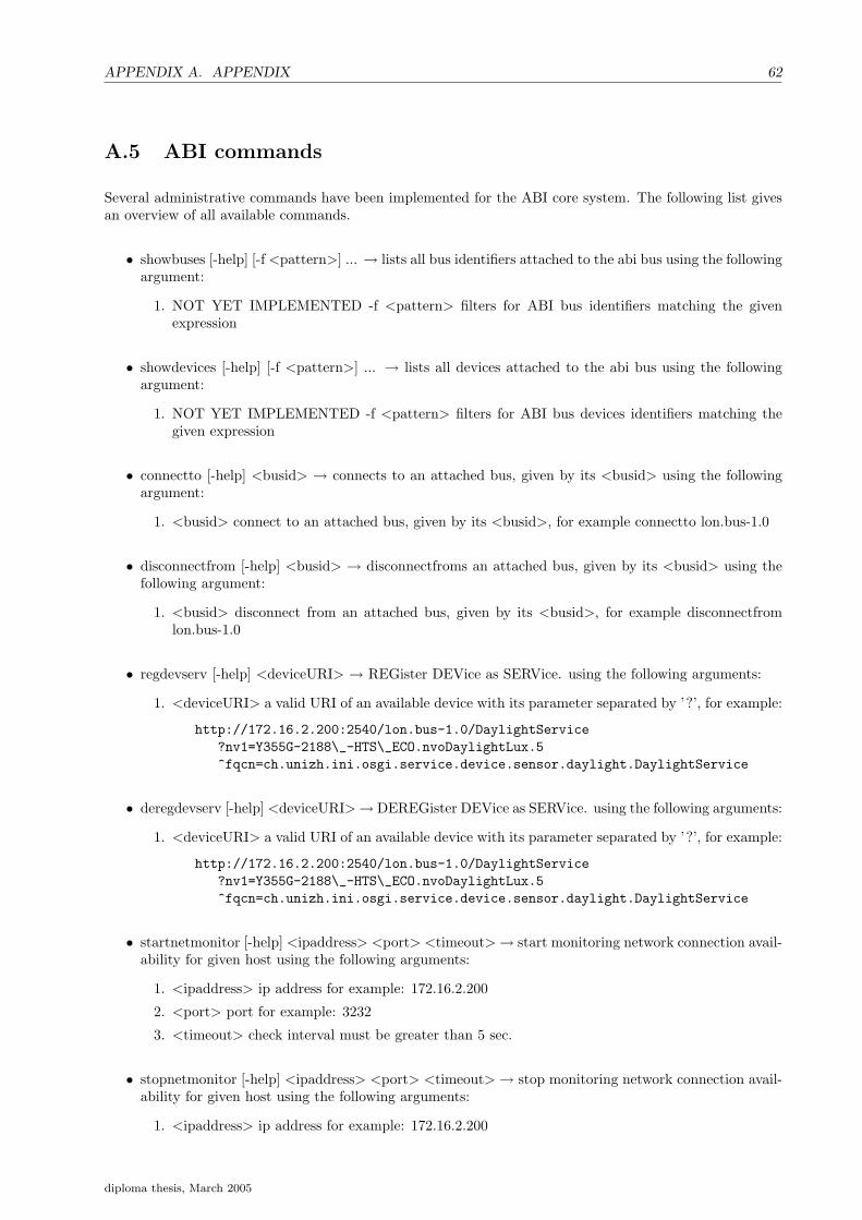
APPENDIX A. APPENDIX 62
A.5 ABI commands
Several administrative commands have been implemented for the ABI core system. The following list givesan overview of all available commands.
• showbuses [-help] [-f <pattern>] ... → lists all bus identifiers attached to the abi bus using the followingargument:
1. NOT YET IMPLEMENTED -f <pattern> filters for ABI bus identifiers matching the givenexpression
• showdevices [-help] [-f <pattern>] ... → lists all devices attached to the abi bus using the followingargument:
1. NOT YET IMPLEMENTED -f <pattern> filters for ABI bus devices identifiers matching thegiven expression
• connectto [-help] <busid> → connects to an attached bus, given by its <busid> using the followingargument:
1. <busid> connect to an attached bus, given by its <busid>, for example connectto lon.bus-1.0
• disconnectfrom [-help] <busid> → disconnectfroms an attached bus, given by its <busid> using thefollowing argument:
1. <busid> disconnect from an attached bus, given by its <busid>, for example disconnectfromlon.bus-1.0
• regdevserv [-help] <deviceURI> → REGister DEVice as SERVice. using the following arguments:
1. <deviceURI> a valid URI of an available device with its parameter separated by ’?’, for example:
http://172.16.2.200:2540/lon.bus-1.0/DaylightService?nv1=Y355G-2188\_-HTS\_ECO.nvoDaylightLux.5^fqcn=ch.unizh.ini.osgi.service.device.sensor.daylight.DaylightService
• deregdevserv [-help] <deviceURI>→ DEREGister DEVice as SERVice. using the following arguments:
1. <deviceURI> a valid URI of an available device with its parameter separated by ’?’, for example:
http://172.16.2.200:2540/lon.bus-1.0/DaylightService?nv1=Y355G-2188\_-HTS\_ECO.nvoDaylightLux.5^fqcn=ch.unizh.ini.osgi.service.device.sensor.daylight.DaylightService
• startnetmonitor [-help] <ipaddress> <port> <timeout> → start monitoring network connection avail-ability for given host using the following arguments:
1. <ipaddress> ip address for example: 172.16.2.200
2. <port> port for example: 3232
3. <timeout> check interval must be greater than 5 sec.
• stopnetmonitor [-help] <ipaddress> <port> <timeout> → stop monitoring network connection avail-ability for given host using the following arguments:
1. <ipaddress> ip address for example: 172.16.2.200
diploma thesis, March 2005

A.5. ABI COMMANDS 63
2. <port> port for example: 3232
• send [-help] <wirePID> <type> <value> → send a new value (command) to a device using an existingwire using the following arguments:
1. <wirePID> wire PID for example: wire.16-14560200878
2. <type> flavour of the wire for example: string
3. <value> message to send, for example: TURN LIGHT OFF,USER
• senddevice [-help] <devicePID> <type> <value> → send a new value (command) to a device notusing a existing wire using the following arguments:
1. <devicePID> receiver PID example:
http://172.16.2.200:2540/lon.bus-1.0/LightService?nv1=Y355G-2187_-PHI_LRC_B.nvo0102LampVal.26^nv2=Y355G-2187_-PHI_LRC_B.nvi0102irSetting.14^nv3=Y355G-2187_-UPL_LT_A.nvoSetting[2].2^nv4=Y355G-2187_-UPL_LT_B.nvoSetting[2].2^nv5=Y355G-2187_-UPL_LT_D.nvoSetting[2].2^fqcn=ch.unizh.ini.osgi.service.device.actuator.light.LightService
2. <type> flavour of the wire for example: string
3. <value> message to send, for example: TURN LIGHT OFF,USER
diploma thesis, March 2005

APPENDIX A. APPENDIX 64
A.6 ABI area commands
Several administrative commands have been implemented for the ABI area. The following list gives anoverview of all available commands.
• create [-help] <structureCategroy> <uniqueID> <location> → creates a new area services using thefollowing arguments:
1. <structureCategroy> a valid structure category either ’room’, ’floor’ and ’building’
2. <uniqueID> area will be registered with this ID, for example 55.G.74
3. <location> well defined location, for example 55.G.74
• remove [-help] <uniqueID> → removes area services using the following argument:
1. <uniqueID> the area service has been registered with this ID
• show [-help] [-f <pattern>] ... → shows all registered area services optional argument:
1. NOT YET IMPLEMENTED -f <pattern> filters for area identifiers matching the given expression
• printqvalues [-help] <areaID> <type> → prints all so far calculated q-values for given area using thefollowing arguments argument:
1. <areaID> the area service has been registered with this ID
2. <type> either ’long’ for long term memory or ’short’ for short term memory.
• memsave [-help] <areaID> <filename> <type> → saves for an area the long term m., short term m.to a file using the following arguments:
1. <areaID> the area service has been registered with this ID
2. <filename> specifies any filename and path
3. <type> either ’long’ for long term memory or ’short’ for short term memory.
• memload [-help] <areaID> <filename> <type> → loads for an area the long term m., short term m.from a file using the following arguments:
1. <areaID> the area service has been registered with this ID
2. <filename> specifies any filename and path
3. <type> either ’long’ for long term memory or ’short’ for short term memory.
diploma thesis, March 2005

A.7. INSTALLATION AND STARTUP 65
A.7 Installation and startup
There are three mandatory installed software packages:
• Java
• Knopflerfish binary, or source distribution
• ABI System related packages must be available in jars folder of the Knopflerfish installation.
The following optional software packages are recommended:
• MySQL data base
• Jive instant messenger
The Knopflerfish framework is started by using the start script which comes with the Knopflerfish distribu-tion. When the Knopflerfish framework is started there are several possibilities how it can be accessed. Thetwo essential ways to interact are described here:
• Graphical user interface, with console
• Telnet console
Installing the ABI System with the graphical user interface is done by choosing the ABI System bundleswith the help of the file dialog. The bundles are then installed and started. The recommended order ofinstalling the bundles is as follows:
• ABInetmonitor
• ABIutil
• ABIfuzzyutil
• ABIreinforcementlearning
• ABIcoreapi
• ABIcorecmd
• ABIare
• ABIarecmd
• ABIlon
• ABImessenger
Installing the ABI System on the telnet console is done by typing the following on the command line:
install file:jars/ABInetmonitor/ABInetmonitor_all-1.0.0.jarfile:jars/ABIutil/ABIutil-1.0.0.jar file:jars/fuzzyutil/fuzzyutil-1.0.0.jarfile:jars/ABIcoreapi/ABIcoreapi_all-1.0.0.jar file:jars/ABIcmd/ABIcmd-1.0.0.jarfile:jars/ABIlon/ABIlon-1.0.0.jar file:jars/ABIarea/ABIarea_all-1.0.0.jarfile:jars/ABIareacmd/ABIareacmd-1.0.0.jarfile:jars/reinforcmentlearningutil/reinforcmentlearningutil-1.0.0.jarfile:jars/ABImessenger/ABImessenger-1.0.0.jar
diploma thesis, March 2005

APPENDIX A. APPENDIX 66
Installing bundles on the command line does not start them automatically as it is the case with using thegraphical user interface. In order to start the previously installed bundles the command line:
start "ABI Net Bundle""ABI Core Bundle""ABI Area Bundle""ABI Area CMD Bundle""ABI CMD Bundle""ABI Lon Bundle""ABI Messenger Bus"
The ABI System is now ready and it can be brought in action by entering the ABI command group andconnecting to different buses available. Try also the help command or command -help to get specific helpfor a command. Check also the appendixes A.5 and A.6 for the ABI commands.
An example output of the showbuses command follows:
> > enter ABI
ABI> ABI> showbuses
----=== .............. ===-------=== Attached Buses ===-------=== jive.bus-1.0 [attached & connected(6)]----=== lon.bus-1.0 [attached & connected(6)]----=== ============== ===-------=== ============== ===---ABI> ABI>
ABI> ABI>
diploma thesis, March 2005

Appendix B
Glossary
Abbreviation Explanation / Comment
ABI Adaptive Building IntelligenceLNS Lon Network ServerLonWorks Field bus network protocol / standardBundles Java JAR archiveManifest OSGi configuration file included in any BundlesWireAmin Bundle originally developed for Oscar OSGiWire Connection object used for producer and consumer conceptsService Interface exportet by the service provider bundleOSGi Open Service Gateway initiativeOSCAR Open source OSGi implementationJSDK Java JSDK 1.4Knopflerfish OSGi Open source OSGi implementationLonMaker Software for LON network allowing browsing and configuring tasksSMF IBM Service Management FrameworkUSB Universal Serial BusJ2ME Java 2 Platform, Micro EditionCLDC Connected Limited Device ConfigurationSR Service referenceSREG Service registrationDA Device AccessSIENA Scalable Internet Event Notification ArchitecturesJMS Java Message ServiceABI Adaptive Building IntelligenceJAR Java ArchiveNV Network VariableEclipse Open source development environmentMySQL Open source databaseRL Reinforcement learningJive Instant messenger serverIM Instant message
Table B.1: Glossary.
67

Bibliography
[BG04] Patrick Brunner and Simon Gassmann. Adaptive building intelligence based on the open servicesgateway initiative, term work. Technical report, University of Applied Sciences Rapperswil, Switzer-land and Institute of Neuroinformatics, Swiss Federal Institute of Technology, Zurich, Switzerland,2004.
[Fuz] Fuzzy Engine by Edward Sazonov. http://people.clarkson.edu/ esazonov/FuzzyEngine.htm.
[Ini03] Open Service Gateway Initiative. OSGi Service Platform Release 3. IOS Press, 2003. ISBN :1-58603-311-5.
[KNO] Knopflerfish. http://www.knopflerfish.org/index.html.
[Lon] LonMark Profile. http://www.lonmark.org/products/fprofile.ht.
[Mit97] Tom M. Mitchell. Machine Learning. McGraw-Hill, 1997. ISBN : 0-07-042807-7.
[OSC] OSCAR an Open Source OSGi Framework Implementation. http://oscar.objectweb.org/.
[RSS98] Andrew G. Barto Richard S. Suttom. Reinforcement Learning. MIT Press, 1998. ISBN : 0-262-19398-1.
[Tra02] Dirk H. Traeger. Einfuehrung in die Fuzzy-Logik. Teubner Verlag, 2002. ISBN : 3-519-16162-1.
[TZ04] Jonas Trindler and Raphael Zwiker. Adaptive building intelligence – parallel fuzzy controlling andlearning architecture based on a temporary and long-term memory. Technical report, University ofApplied Sciences Rapperswil, Switzerland and Institute of Neuroinformatics, Swiss Federal Instituteof Technology, Zurich, Switzerland, 2004.
68

Index
ABI System, 17architecture, 21
bundle, 18, 20context, 20life cycle, 20
filter, 20grammar, 20
Fuzzy controlfuzzy control circuit, 15fuzzy library, 15
Hardware issuesblind device, 44daylight device, 44intervisibility, 48out of sync, 44presence device, 48
Long and short term memorymemory, 13merge Q(s, a) values, 13time period, 13
OSGi, 19bundle, see bundlefilter, see filterservice, see service
Punishmentdelayed reward, 13negative rewards, 13punishment, 13user interaction, 13
Reinforcement learningdiscount, 6model, 4policy, 4R-learning algorithm, 7reward function, 4step size, 5, 7task, 5TD, 6Temporal-Difference, 6value function, 4
service, 20
implementation, 20reference, 20registration properties, 20
Virtual devicesbusyness presence service, 42smoothed presence service, 42virtual devices, 39
69