ad8600 & nb-ad8600 concealed vertical rod exit … bulletins/june 2009... · ad8600 &...
TRANSCRIPT

Copyr ight©1998-2009,Sarge nt Manufa cturingComp any, anASSAABLOYGrou pcompany.Allr ightsreserved.
Reproductioninwholeorinpartwithout th eexp re sswrittenp er miss iono fSargent Ma nufacturingComp anyisprohibited.
AD8600 & NB-AD8600Concealed Vertical Rod Exit Devicefor Aluminum Doors80 Series
640 Top & Bottom Strike
• Steel with Black Nylon Coating
• Machine Screws Supplied
1-800-461-3007 • www.assaabloy.ca24
Door Types Aluminum, 1-3/4" (44 mm) minimum thickness.For doors over 1-3/4" to 2-1/4" thick, specify thickness and order as 31- option4-1/2" (114mm) minimum stile width
Door Widths E Rail - 24" to 32" (61cm to 81cm) No cutting required for 32" doorF Rail - 33" to 36" (84cm to 91cm) No cutting required for 36" doorJ Rail - 37" to 42" (94cm to 107cm) No cutting required for 42" doorG Rail - 43" to 48" (110cm to 122cm) No cutting required for 48" door
Strike 640 Strikes for Top & Bottom StrikeDogging Feature Hex key dogging standard; Cylinder Dogging available (16-)Electric Options AL- Alarm Option - Page 61
BT- Beacon™ Option - Page 59PL- SARGuide Photoluminescent Coated Option - Page 60TL- SARGuide Illuminated Touchpad Option - Page 6053- LX Latchbolt Monitor Option - Page 6054- Outside Lever Monitoring Option- Page 6755- Request-to-Exit Signal - Rail Monitoring Option - Page 6156- ELR Remote Latch Retraction Option - Page 62-6357- Delay Egress Option & Electromagnets - Page 64-6558- Electric Dogging Option - Page 6659- Electroguard – Self Contained Delayed Egress Option (NB- Excluded) - Page 66
Mounting Fasteners Supplied standard with machine screwsTop Bolt Stainless steelDevice Centerline from 41” (1041 mm) for Standard ApplicationsFinished Floor 38" (965mm) for elementary schools and to meet local accessibility standards
when a 100 Series Auxiliary Control is usedDoor/Opening Height Must be specified - 120" (3048mm) Max Door OpeningCenter Case Dimensions 8-3/8" (213mm) x 2-5/8" (67mm)Projection Pushbar Neutral – 3" (76 mm)
Pushbar Depressed – 2-1/8" (54 mm)Fire Exit Hardware Not Available
Specifications for AD8600 & NB-AD8600 Series Exit
Features• Designed for standard width stileapplications on aluminum doors
• Concealed rods for security andaesthetics
• Single and double door applications• Specify NB- for less bottom rod• Devices are ANSI A156.3 – 2008 Grade 1• UL Panic listed only
AD8600 SeriesConcealed Vertical Rod Exit Devicefor Aluminum Doors
2.00in50.80mm
1.21in30.73mm
.25in6.35mm
2"(50.80mm)
.25"(6.35mm)
Ø1.21"(30.73mm)
Note: AD8600 can be used as NB- Device by simply not installingthe bottom rod/bolt.
NB-AD8600 AD8600
100 Series Aux Control
• Available as an 06 or 13function
• Supplied with aSARGENT #41 MortiseCylinder
• Can be used with anySARGENT Mortise KeySystem
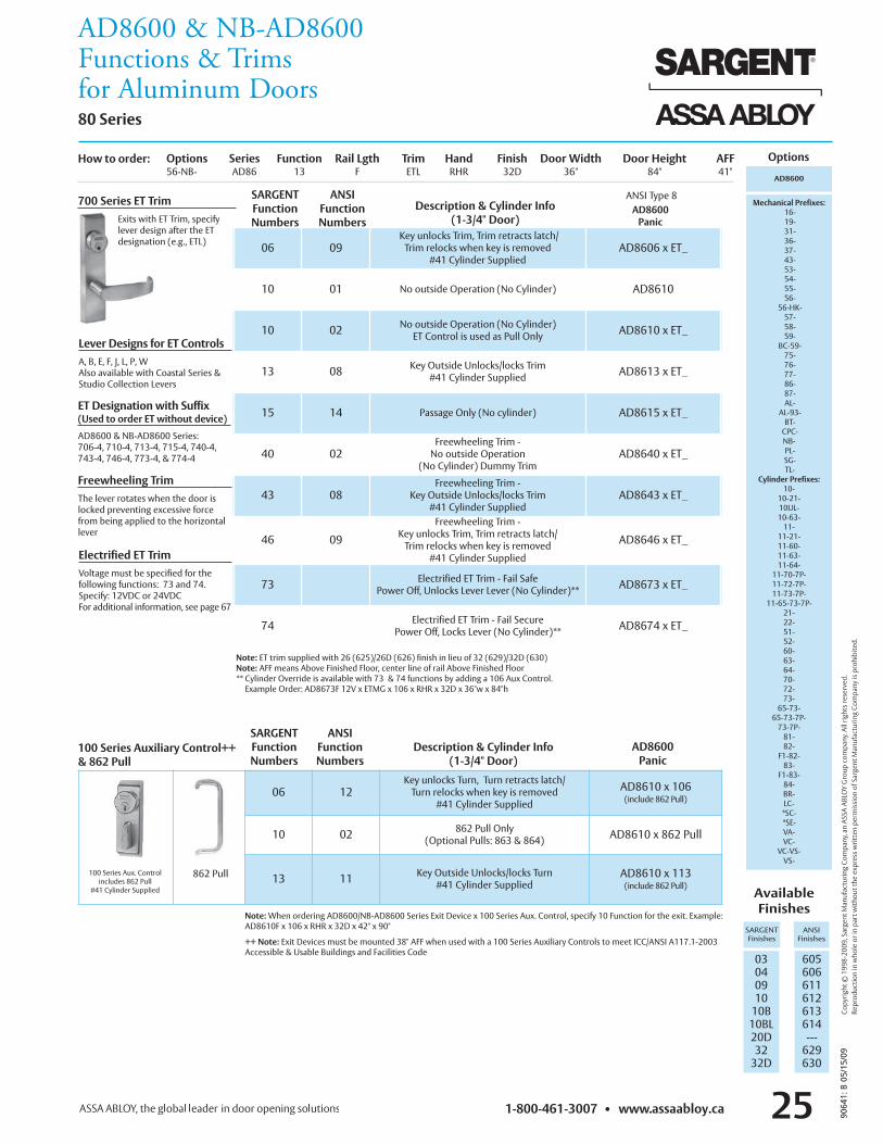
AD8600 & NB-AD8600Functions & Trimsfor Aluminum Doors80 Series
1-800-461-3007 • www.assaabloy.ca 25
ANSI Type 8
Options
Lever Designs for ET ControlsA, B, E, F, J, L, P, WAlso available with Coastal Series &Studio Collection Levers
Freewheeling TrimThe lever rotates when the door islocked preventing excessive forcefrom being applied to the horizontallever
Electrified ET TrimVoltage must be specified for thefollowing functions: 73 and 74.Specify: 12VDC or 24VDCFor additional information, see page 67
Note: ET trim supplied with 26 (625)/26D (626) finish in lieu of 32 (629)/32D (630)Note: AFF means Above Finished Floor, center line of rail Above Finished Floor** Cylinder Override is available with 73 & 74 functions by adding a 106 Aux Control.Example Order: AD8673F 12V x ETMG x 106 x RHR x 32D x 36"w x 84"h
AvailableFinishes
SARGENTFinishes
ANSIFinishes
0304091010B10BL20D3232D
605606611612613614---629630
700 Series ET TrimExits with ET Trim, specifylever design after the ETdesignation (e.g., ETL)
Options Series Function Rail Lgth Trim Hand Finish Door Width Door Height AFF56-NB- AD86 13 F ETL RHR 32D 36" 84" 41"
06 09Key unlocks Trim, Trim retracts latch/Trim relocks when key is removed
#41 Cylinder SuppliedAD8606 x ET_
10 01 No outside Operation (No Cylinder) AD8610
10 02 No outside Operation (No Cylinder)ET Control is used as Pull Only AD8610 x ET_
13 08 Key Outside Unlocks/locks Trim#41 Cylinder Supplied AD8613 x ET_
15 14 Passage Only (No cylinder) AD8615 x ET_
40 02Freewheeling Trim -No outside Operation
(No Cylinder) Dummy TrimAD8640 x ET_
43 08Freewheeling Trim -
Key Outside Unlocks/locks Trim#41 Cylinder Supplied
AD8643 x ET_
46 09Freewheeling Trim -
Key unlocks Trim, Trim retracts latch/Trim relocks when key is removed
#41 Cylinder Supplied
AD8646 x ET_
73 Electrified ET Trim - Fail SafePower Off, Unlocks Lever Lever (No Cylinder)** AD8673 x ET_
74 Electrified ET Trim - Fail SecurePower Off, Locks Lever (No Cylinder)** AD8674 x ET_
AD8600
Mechanical Prefixes:16-19-31-36-37-43-53-54-55-56-56-HK-57-58-59-BC-59-75-76-77-86-87-AL-AL-93-BT-CPC-NB-PL-SG-TL-
Cylinder Prefixes:10-10-21-10UL-10-63-11-11-21-11-60-11-63-11-64-11-70-7P-11-72-7P-11-73-7P-11-65-73-7P-
21-22-51-52-60-63-64-70-72-73-65-73-65-73-7P-73-7P-81-82-F1-82-83-F1-83-84-BR-LC-*SC-*SE-VA-VC-VC-VS-VS-
Note:When ordering AD8600/NB-AD8600 Series Exit Device x 100 Series Aux. Control, specify 10 Function for the exit. Example:AD8610F x 106 x RHR x 32D x 42" x 90"
++ Note: Exit Devices must be mounted 38" AFF when used with a 100 Series Auxiliary Controls to meet ICC/ANSI A117.1-2003Accessible & Usable Buildings and Facilities Code
AD8600Panic
Description & Cylinder Info(1-3/4" Door)
SARGENTFunctionNumbers
ANSIFunctionNumbers
AD8600Panic
How to order:
06 12Key unlocks Turn, Turn retracts latch/Turn relocks when key is removed
#41 Cylinder Supplied
AD8610 x 106(include 862 Pull)
10 02 862 Pull Only(Optional Pulls: 863 & 864) AD8610 x 862 Pull
13 11 Key Outside Unlocks/locks Turn#41 Cylinder Supplied
AD8610 x 113(include 862 Pull)
862 Pull
SARGENTFunctionNumbers
Description & Cylinder Info(1-3/4" Door)
100 Series Auxiliary Control++& 862 Pull
ANSIFunctionNumbers
100 Series Aux. Controlincludes 862 Pull
#41 Cylinder Supplied
ET Designation with Suffix(Used to order ET without device)
AD8600 & NB-AD8600 Series:706-4, 710-4, 713-4, 715-4, 740-4,743-4, 746-4, 773-4, & 774-4
9064
1:B
0 5/1
5 /09
Copyr ight©1 99 8-20 09 ,SargentManu fact ur ingC ompany,anASSAA BLOYGr ou pc ompan y. Allr ightsrese rved.
Reproduct ioninwh oleo rinpartwitho ut theexp re sswritt enp ermissio nofSargentManu fact ur ingC ompanyisp ro hibit ed .

1-800-461-3007 • www.assaabloy.ca349064
1:B
05/1
5/09
Copyr ight©1998-2008,Sarge nt Manufa cturingComp any, anASSAABLOYGrou pcompany.Allr ightsreserved.
Reproductioninwholeorinpartwithout th eexp re sswrittenp er miss iono fSargent Ma nufacturingComp anyisprohibited.
AD8400 & NB-AD8400 Narrow StileConcealed Vertical Rod Exit Devicefor Aluminum Doors80 Series
AD8400 NB-AD8400
AD8400 & NB-AD8400 Features• Designed for narrow stile aluminum door applications (e.g., full glass doors)• Concealed rods for security and aesthetics• UL Panic listed only• Specify NB- for less bottom rod• NB- Devices allows free access for wheelchairs and carts. No bottom strikeeliminates tripping potential• All functions determined by outside trim• Devices are ANSI A156.3 – 2008– Grade 1
AD8400 SeriesConcealed Vertical Rod Exit Devicefor Aluminum Doors
Door Types Hollow or extruded aluminum doors.For doors over 1-3/4" to 2-1/4" thick, specify thickness and order as 31- option1-3/4" (44mm) minimum stile width required. Stile must be hollow withinside dimension of at least 1-3/8" (35mm) square
Door Widths E Rail - 24" to 32" (61cm to 81cm) No cutting required for 32" doorF Rail - 33" to 36" (84cm to 91cm) No cutting required for 36" doorJ Rail - 37" to 42" (94cm to 107cm) No cutting required for 42" doorG Rail - 43" to 48" (110cm to 122cm) No cutting required for 48" door
Strike 640 Strike for Top & BottomDogging Feature Hex key dogging standard; Cylinder Dogging available (16-)Electric Options AL- Alarm Option - Page 61
BT- Beacon™ Option - Page 59PL- SARGuide Photoluminescent Coated Option - Page 60TL- SARGuide Illuminated Touchpad Option - Page 6053- LX Latchbolt Monitor Option - Page 6054- Outside Lever Monitoring Option- Page 6755- Request-to-Exit Signal - Rail Monitoring Option - Page 6156- ELR Remote Latch Retraction Option - Page 62-6357- Delay Egress Option & Electromagnets - Page 64-6558- Electric Dogging Option - Page 6659- Electroguard – Self Contained Delayed Egress Option (NB- Excluded) - Page 66
Mounting Fasteners Supplied standard with machine screwsTop Bolt Stainless steelDevice Centerline from 41” (1041 mm) for Standard ApplicationsFinished Floor 38" (965mm) for elementary schools and to meet local accessibility standards
when a 100 Series Auxiliary Control is usedDoor/Opening Height Must be specified - 120" (3048mm) Max Door OpeningCenter Case Dimensions 8-3/8" (213mm) x 2-5/8" (67mm)Projection Pushbar Neutral – 3" (76 mm)
Pushbar Depressed – 2-1/8" (54 mm)Fire Exit Hardware Not Available
Specifications for AD8400 & NB-AD8400 Exit
100 Series Aux Control
Note: AD8400 can be used as NB- Device by simply not installing the bottom rod/bolt.
• Available as an 06 or 13function
• Supplied with aSARGENT #41 MortiseCylinder
• Can be used with anySARGENT Mortise KeySystem
640 Top & Bottom Strike
• Steel with Black Nylon Coating
• Machine Screws Supplied
2.00in50.80mm
1.21in30.73mm
.25in6.35mm
2"(50.80mm)
.25"(6.35mm)
Ø1.21"(30.73mm)

1-800-461-3007 • www.assaabloy.ca 35 9064
1:B
0 5/1
5 /09
Copyr ight©1 99 8-20 08 ,SargentManu fact ur ingC ompany,anASSAA BLOYGr ou pc ompan y. Allr ightsrese rved.
Reproduct ioninwh oleo rinpartwitho ut theexp re sswritt enp ermissio nofSargentManu fact ur ingC ompanyisp ro hibit ed .
AD8400 & NB-AD8400Functions & Trimsfor Aluminum Doors80 Series
Options Series Function Rail Lgth Trim Hand Finish Door Width Door Height AFF55- AD84 13 F ETL RHR 32D 36" 84" 41"
ANSI Type 6
Options
AD8400Panic
AD8400
Mechanical Prefixes:16-19-31-36-37-43-53-54-55-56-56-HK-57-58-59-BC-59-75-76-77-86-87-AL-AL-93-BT-CPC-NB-PL-SG-TL-
Cylinder Prefixes:10-10-21-10UL-10-63-11-11-21-11-60-11-63-11-64-11-70-7P-11-72-7P-11-73-7P-11-65-73-7P-
21-22-51-52-60-63-64-70-72-73-65-73-65-73-7P-73-7P-81-82-F1-82-83-F1-83-84-BR-LC-*SC-*SE-VA-VC-VC-VS-VS-
Lever Designs for ET ControlsA, B, E, F, J, L, P, WAlso available with Coastal Series &Studio Collection Levers
Freewheeling TrimThe lever rotates when the door islocked preventing excessive force frombeing applied to the horizontal lever
Electrified ET TrimVoltage must be specified for thefollowing functions: 73 and 74.Specify: 12VDC or 24VDCFor additional information, see page 67
Note: ET trim supplied with 26 (625)/26D (626) finish in lieu of 32 (629)/32D (630)Note: AFF means Above Finished Floor, center line of rail Above Finished Floor** Cylinder Override is available with 73 & 74 functions by adding a 106 Aux Control.Example Order: AD8473F 12V x ETMG x 106 x RHR x 32D x 36"w x 84"h
AvailableFinishes
SARGENTFinishes
ANSIFinishes
0304091010B10BL1520D3232D
605606611612613614——629630
700 Series ET TrimExits with ET Trim, specifylever design after the ETdesignation (e.g., ETL)
06 09Key unlocks Trim, Trim retracts latch/Trim relocks when key is removed
#41 Cylinder SuppliedAD8406 x ET_
10 01 No outside Operation (No Cylinder) AD8410
10 02 No outside Operation (No Cylinder)ET Control is used as Pull Only AD8410 x ET_
13 08 Key Outside Unlocks/locks Trim#41 Cylinder Supplied AD8413 x ET_
15 14 Passage Only (No cylinder) AD8415 x ET_
40 02Freewheeling Trim -No outside Operation
(No Cylinder) Dummy TrimAD8440 x ET_
43 08Freewheeling Trim -
Key Outside Unlocks/locks Trim#41 Cylinder Supplied
AD8443 x ET_
46 09Freewheeling Trim -
Key unlocks Trim, Trim retracts latch/Trim relocks when key is removed
#41 Cylinder Supplied
AD8446 x ET_
73Electrified ET Trim - Fail Safe
Power Off, Unlocks Lever (No Cylinder)**Specify: 12VDC or 24VDC
AD8473 x ET_
74Electrified ET Trim - Fail Secure
Power Off, Locks Lever (No Cylinder)**Specify: 12VDC or 24VDC
AD8474 x ET_
AD8400Panic
SARGENTFunctionNumbers
ANSIFunctionNumbers
Description & Cylinder Info(1-3/4" Door)
How to order:
Note:When ordering 8400 Series Exit Device x 100 Series Aux. Control,specify 10 Function for the exit. Example: AD8410F x 106 x RHR x 32D x 42" x 90"
++ Note: Exit Devices must be mounted 38" AFF when used with a 100 Series Auxiliary Controls to meet ICC/ANSI A117.1-2003Accessible & Usable Buildings and Facilities Code
06 12Key unlocks Turn, Turn retracts latch/Turn relocks when key is removed
#41 Cylinder Supplied
AD8410 x 106(include 862 Pull)
10 02 862 Pull Only(Optional Pulls: 863 & 864) AD8410 x 862 Pull
13 11 Key Outside Unlocks/locks Turn#41 Cylinder Supplied
AD8410 x 862 Pull(include 862 Pull)
862 Pull
SARGENTFunctionNumbers
100 Series Auxiliary Control++& 862 Pull
ANSIFunctionNumbers
100 Series Aux. Controlincludes 862 Pulland #41 Cylinder
ET Designation with Suffix(Used to order ET without device)
8400 & NB-8400 Series: 706-4, 710-4,713-4, 715-4, 740-4, 743-4, 746-4,773-4, & 774-4