ad-767 280 the interaction of a hypersonic … · 1442, amendment 2 program code 9e3d the...
TRANSCRIPT

pp i PW IPIIM.MIH.IK ..i in ««IIIIMIIWIH »- , Mf W-|i|IWlW|tWI«IP^WII<UmJ|IUI>UNUWVIUniiWV..I«IIIIIIJIJi ilUWJ^mffP^HIHII ■lll.miV^MQ^^I mVJIIVilJIJ WL^IRPJMM IUIIWPWIJIIJ^U^
.
AD-767 280
THE INTERACTION OF A HYPERSONIC PLUME WITH AN EXTERNAL HYPERSONIC STREAM
John T. Kelly
Polytechnic Institute of Brooklyn
Prepared for:
Army Research Off ice-Durham Advanced Research Projects Agency
July 1973
DISTRIBUTED BY:
KHJ National Technical Information Service U. S. DEPARTMENT OF COMMERCE 5285 Port Royal Road, Springfield Va. 22151
... . : . .■..■■■■■ ■ ■ ' ■
iit.ii.-if—t>fi:..^ .,.■,■-■-....■.^„ rf-^-j^ir ._■...■ - ,>. .-.■.... ■-. ■-,■■.. .-, ,jJ^^\\il^^,<JÜr^,.-MMiä'^tk:ii*AiS.-.y\:y. ■.--■: ■

i^ i iwuniLiuipiLiJiiiumiwiiiii« imiiiii.iiü« ui iu i***mmii*«ß*Mmw\mM!.H.Mi.mmmmuimm *>mn "", wmmmmmmm^m fmm.
$ Ni
w i
I—I ru
00
CO
ft
•35
CONTRACT NO. DAHCD4-69-C-DG77 ARPA ORDER NO. 1442, AMENDMENT 2 PROGRAM CODE 9E3D
THE INTERACTION OF A HYPERSONIC PLUME
WITH AN EXTERNAL HYPERSONIC STREAM
by
JOHN T. KELLY
i«^^,
D D r .„,(■
r-ff
OCT 3 1975-
POLYTECHNIC INSTITUTE OF BROOKLYN
DEPARTMENT of
AEROSPACE ENGINEERING and
APPLIED MECHANICS
JULY 1973 I) APPROVED TOR PUBLIC RELEASE;
OISTRIBUTIOM UNLIMITED.
Reproduced by
NATIONAL TECHNICAL INFORMATION SERVICE
US Department of Commerce Springfield, VA. 22151
PIBAL HEPDHT No. 73-12
Jaüa ...1i.^^1.c,ljrm^l^.^.^iJSi-- —■ ^ -■ ^-■^■^■^ .. ^J.^-„..- --
■--«Mi^—.ll ■ 1
ihHÜiinilil'iriii" n" HI i VM ri-i.

■M''™m>»ww«ij!j»iiii^i^^^
Unclassified ^SecurityClaBsification
DOCUMENT CONTROL DAT^ - R & D (Security r/...f<ic.Hon ol il,„. body ol ah.,„cl .nd lnd,,lnS .nnoHllon mual he ,„,.,.d»h»n the ov,..„ „po,, Is cla.Bllfd)
I ORIGINATING ACTIVITY fCo/po«/« «Ulhorj •J^~^^^" -~ '
Polytechnic Institute of Brooklyn Dept. of Aerospace Eng. & Applied Mechanics Route 110,, Farmingdale, New York 11735
2». FiePORT SECURITY CLASSIFICATION
Unclassified 2b. GROUP
3 REPORT TITLE ——— _
THE INTERACTION OF A HYPERSONIC PLUME WITH AN EXTERNAL HYPERSONIC STREAM
4. DESCRIPTIVE NOTES (Type ol report and Inclusive datta)
Research Report 5. AUTHORIS) (Flrsl name, middle initial, last name)
John T. Kelly
6 REPORT DATE
July 1973 7«. TOTAL N
8«. CONTRACT OR GRANT NO. . — - , „
DAHC04-69-C-0077 6. PROJEC T NO.
=■ ARPA Order No. 1442, Amendment 2
d Program Code 9E30
O, OF PAGES 7b. NO. OF REFS
36 9«. ORIGINATOR'S REPORT NUMBER(S)
PIBAL Report No. 73-12
ab. OTHER REPORT NOIS» (Any other numbers that may be aeelimed this report) '
10 DISTRI BUTIOK STATEMENT
Approved for public release; distribution unlimited.
II. SUPPLEMENTARY NOTES
13 ABSTB^t T
12. SPONSORING MILITARY ACTIVITY
U.S. Army Research Office Box CM, Duke Station Durham, North Carolina 27706
A theoretical study of the gas dynamic interaction between a hyper- sonic plume and the opposed hypersonic external stream is presented. Steady, axisymmetric, inviscid, perfect gas flow is postulated for both the bow and far field regions. Limiting forms of solutions are obtained for the bow region by application of the Newton-Busemann approximation (i.e., ee,eio-0 M0Oe,M0Oio-<» such that M^e^M^ ^e^-O (1) ) to both
the exhaust plume and ambient air flow. Through asymptotic expansions and their matching, it is found that six regions are required to ade- quately describe the bow region. For the far field region, the hyper- sonic small-disturbance form of the Newton-Busemann approximation (i.e., Se-0» MODe-0, i5e-»0 such that M^ e 5^-0 (1)) is applied. From asymptotic'
expansions and their matching, it is found that "entropy wake" solutions are required to adequately describe the exhaust flow and the air flow near the contact surface. Analytical solutions are obtained which (i) define scaling parameters for the bow and far field flow; (ii)esti- mate the accuracy of the Newtonian impact theory in predicting bow region geometry and properties; (iii) establish the variation of bow and far field properties with variation in the primary system design parameters'.
DD FORM I NO V SS 1473 Unclassified
i«/ Security Classification
.'
^..-■■LJI.II^.V.^-I^.....'—--.■.--■^:v1.,-
■
.....l^-.^ ■J^.-. -..,:■■ . _,U ■nAhiü.tfMrrtoftritt'^n IftiMüÜWäMiWfc;

LIU «■'i>c.»"-»»*""i-.'i"<wi ii i ■ .IJJII'JIJI ,iii|iijpiiuiiMijw.iiji4^^RnMPWjuiJi|illluijii^wnMmwM>^H^i^wiiJ i ii iv^^t^mm^m^mm^ti m n—i .1111«
Unclassified Security Classification
KEY K'ONOt HOLE WT nouE
Plume interaction Hypersonic Retro configuration
•b Unclassified Security Classification
fatfarii ^-^--■-v.::..v-->-^..^^.m^—^^it- nil l^lAüV1tt"lnli■iil^"^lli^ im - - ----1 mViTiiiirniiftinirn M .^^.^^^^.^.. L^m,^A;)-1<l^,i.ai-.-/J,v^.;-.J^,^lii.JH«i,-^>^j,.vc -.^.^.„^...^■^i.L^j^^j^^.^-.. ■..;.. ..: : -^ .:.■:..■, .L^.^-v^a;

•■ "■■»'»"'"■'"'"«"""'■•'•'■■"-'-"^^
THE INTERACTION OF A HYPERSONIC PLUME
WITH AN EXTERNAL HYPERSONIC STREAM
by
John T. Kelly
This research was sponsored by the Advanced Research Projects Agency of the Department of Defense and was monitored by the U.S. Army Research Office, Durham, North Carolina under Contract No. DAHC04-69-C-0077.
Reproduction in whole or in part is permitted for any purpose of the United States Government.
Polytechnic Institute of Brooklyn
Department
of
Aerospace Engineering and Appliec* Mechanics
July 1973
PIBAL Report No. 73-12
Approved for public release; distribution unlimited,
fC
hmni'i nr > — -■■■^-■--ii|-i>iiinniMifiirmniJriirr'c—-"-'-'- -""-■•—•■- ^...„.t..^^—^*^^**^^ .■^■^■..■■.■.w^.^....,... ..... ;.W^U-lJ,:ii.i^.;.Au:vit»lc«iv.ii^1il/.L:.-..;.. .,, ..... ,■■,.,....-^'^v.„iijJ.,;.ni1uJ,Aa

HI iaiiu*p..*.«iiuiin4iiii luni.juiiip.iiwwwfwww^mw .uiiiiiMI-iilMlimiMiJIiui -ni|i,iWilP^iJW»iiii||i.Mii*!ii,iWilllWiW«l« IIIIIUi-IJ|ilJWMIUIi«iUllWi|*l!*»t*W«HW*;l
THE INTERACTION OF A HYPERSONIC PLUME
WITH AN EXTERNAL HYPERSONIC STREAMt
by
John T. Kelly
Polytechnic Institute of Brooklyn Preston R. Bassett Research Laboratory
Fartningdale, New York
ABSTRACT
A theoretical study of the gas dynamic interaction between a
hypersonic plume and the opposed hypersonic external stream is
presented. Steady, axisymmetric, inviscid, perfect gas flow is
postulated for both the bow and far field regions. Limiting
forms of solutions are obtained for the bow region by application
of the Newton-Busemann approximation (i.e., e ,e. -0 M „M -oo 2 2 e 10 ooe» ooio
such that M ep»M e. -0(1)) to both the exhaust plume and UJ e •= oo IQ ■LU
ambient air flow. Through asymptotic expansions and their matching,
it is found that six regions are required to adequately describe
the bow region. For the far field region, the hypersonic small-
disturbance form of the Newton-Busemann approximation (i.e., e -0,
Mooe'*0,6e-'0 such that Moo 6eee~0(1)) is aPPlied- From asymptotic
This research was supported by the Advanced Research Projects Agency of the Department of Defense and was monitored by the U.S. Army Research Office, Box CM, Duke Station, North Carolina 27706, under Contract No. DAHC04-69-C-0077.
The author would like to thank Prof. S. G. Rubin, for his invaluable discussions during the course of this work.
Currently at Aerochem Research Labs., Princeton, New Jersey.
ib
.—:. ^.,,. -^ mJAjaaa^ma.... -u.... ^[|....,|I1.,,„.,. -^^ iM.. - ^- ^.■■^^, .■^.■., .:..J^.u1^.^^. .■.■,..-,.--.... ^ ,^._ .,_-■■■..... ,.■■..■. IU^^IMU^JUL-.:, u.. w^.^'i.'. lii.- ■vlitjj.i.-i^iÄj^ö; : i.t .*JiJjfcl.i-k^iii'J.

^■™ .u.i,iiM(inj,iwiwi«.»..iwi,., ..iiAMJ-M»iiij'j!"i.JiJi.,w!^"jj...j(ii.«wiji!«wj,ip^j»i-i«»,wu«i I,I»»,....II.«-. 'OT' r™^wwKj,11,!»^,;um,,mKmiim\.ß^umuu*». ji j.igii.tipiiuwi.mn.wMi npiPM«».«iHWiaun"!.'"..!. ij ij mipfiji
expansions and their matching, it is found that "entropy wake"
solutions are required to adequately describe the exhaust flow and
the air flow near the contact surface. Analytical solutions are
obtained which (i) define scaling parameters for the bow and far
field flow; (ii) estimate the accuracy of the Newtonian impact
theory in predicting bow region geometry and properties; (iii) estab'
lish the variation of bow and far field properties with variation
in the primary system design parameters.
11
' tnv-r n r r !! miM^r-----;J-°^"^-J-'^"--^-^iM^niiiirltfili-ii •■--•■-''"•'",-t-^''^t:^^mi^^ -

Hlij.. Ui,"" i I i .. ii.......»!.!»! ^.uu» Ui ii<il i, m_«iiJ1IP.I<>WJ|i«<i.iliil.> •-."'«'».lu.ii .1.1 ■ i in -ii njaiuLii ;i ..u.KiiiiiiinnuLuuui.« an HIIIIIIIUiKUUVIUI I IJIH J iiaiiujinu.uii^iwii.ui»" milllUiu»
TABLE OF CONTENTS
«I
Section Pare
I Introduction 1
II Jet Exhaust Model 14
III Analysis of Bow Region 19
IV Discussion of Results 69
V Analysis of Corner Region 79
VI Far Field Region Analysis 91
VII Discussion of Results 119
VIII Conclusions 121
IX References ....; 124
Appendix (A) Bow Initializing Scheme 127
111
T aiJfa1Jaw.!^..~i..^^.j.w^.. ....■ -..^.-^^^.^^^w,^^ :M**^^^^*^^ ..w-. ...--■.■•■..^^-■^ . .^
TiniiimMTiOTiirpn-

•^-^..,l|wj^|4^^i.iV:MW.M>*.^rW^
LIST OF FIGURES
Page 1 Schematic of Jet and External Flow
Interaction 130
2 Flow Regimes ......... ^ 131
3 .Undisturbed Plume Model Exponent as a Function of Angle and Distance 132
4 Experimentally Determined Shock and Contact Surface Locations Referred t0 R»«, 133
5 Predicted Contact Surface Shapes 134
6 Comparison of Shock and Contact Surface Positions 135
7 Comparison of Contact Surface Pressure Distributions I36
3 Comparison of Calculated Shocks and Contact Surface Positions with Experi- mental Results of Zakkay I37
9 Contact Surface Pressure Distribution. 138
10 Variation of Bow Geometry with n 139
11 Variation of Bow Geometry with 9<p .... 140
12 Variation of Contact Surface Pressure with 6» 1^1
13 Vari ation of Bow Geometry with Xj ... 142
14 Variation" of Contact Surface Pressure with *) 143
15 Isobars and Streamlines for Bow Region 144
16 Density and Velocity Distributions for Bow Region X45
17 Isobars and Streamlines for Bow Region 1/f5
IV
t"-:':-'--' - —■■■'■-- ;-^"^^^^°^^^^"^"^---,^""-^iiniilirirm ^J1'''^J^''""a,!',"'t"MJ,M*"^^"-^^^ -....l~tJ.^,.,.,..;...<.,.„...,.^i.>,,.^.,..^-..,-1^w,.....:-.,-^.^-;-..- -- .-

■ --.-rvrr-^WT*™.*^***^^*?!^^
LIST OF FIGURES (continued)
10 Density and Velocity Distributions for Bow Region ;u 7
19 Corner Region 1/^
20 .Core Pressure to Ambient Pressure vs. Jet Exit Mach Number , 149
21 Far Field Shock and Contact Surface Position , ]_50
22 Far Field Shock and Contact Surface Position „ -|_c]_
23 Far Field Properties vs. Stream Function 2.52
24 Far Field Properties vs. Stream Function , ^ -jco
■■..^.„„.■...■..„■.■.,^...-^.,..J.,..^, ■ iiijiiiiiiiiiffiimmiinifti^^^^ -..a-...,.^-.J... ■ I IB^IBMMBCMBMMBI'
'-"'" - ■ I - — — -— ■■■-.-- . , ^^^M

ätiB
LIST OF SYMBOLS
t
c Plume model angle parameter
D Body diameter
F Deviation of internal shock from a sphere
Fx Axial force
H Ratio of radius o-J curvature of flow streamlines with- in layer to that of the shock
L Streamwise length scale
M Mach number
n Plume exponent
p Pressure
q Streamline velocity
r Distance measured away from axis
R Radius measured from jet in bow region or distance away from axis in far field region
T Temperature
u Velocity parallel to shock
U Free stream velocity
v Velocity normal to shock
x Distance measured along shock
y Bow region layer thickness
Y Far field layer thickness
ß Shock angle in corner and far field
5 Layer thickness
C Density ratio across shock
if Ratio of specific heats
lo Radius of curvature
VI
• ■ .*•«**
.,.;■■ ,.,,...,^,..-,1 .- ..-,... ^.m:.-.^.,.^a....^.>-..J„.^.WJ...^..,..-.-.l/,.,,-.Hi..,^l...... .. ,..,.... ........U^.... .— -. , .:...,.,..,.....^I..^..-,...1. ...,..,■ ^

i ■»■■" «M Hü — ■ '"•■' "i" '■• ' "*• mmwimm i i lURFMEMMfWRMuwin.ui-' .miim« ■uwii-i \\ \ mwmmmmmmmmmmmmmmmBmmBm
n
ir
LIST OF SYMBOLS (continued)
Ratio of calculated n to analytical approximation
Viscosity
An£;le measured from jet centerline
Ratio of jet stagnation to free stream dynamic pressure
Streamfunction
Shock angle for bow region
Limiting angle for flow into a vacuum
0,1,2.
cs
e
<♦
o
je
s
00
SUBSCRIPTS
Denotes the order of the terra in the expansion
Contact surface
External flow properties
Internal flow properties
Point at which flow has crossed shock
At internal normal shock point
Layer
Shock surface
Free stream condition
Vll
tf«i.»SifiWi-i^^,.;(i,.-.- ...\.\ .■Jiii.«y«^ii.j.' iSi^db'ü&n&Uf a > :,..■ ..■..■ ..:.,.:■.;... ■:■:■... ,....: *.-,-ji«'^3-aL'.i ^-..-.„^■-.-.^■l-iiWi.'Alv. ..i:--&..^t-K,f

■ ■ ■■
INTRODUCTION
A theoretical study of the interaction of a highly underex-
panded jet issuing into a high Mach number free stream that
is opposed to the jet's expansion along its axis is present-
ed. At some distance, characterized by the lengtn R-ai«
the jet and free stream gases interact. The jet flow is there-
by deflected downstream by the external flow. The particular
case of interest to be examined in this study concerns flows
where the typical dimension of the body D is much less
than RsCo (see schematic (1)).
Schematic (1)
- ----- - - ----- -~ »«iiieniU■■"■■'*■ ■. ■ mmm imtä lrllTllif^iTtMl^iliiiif^:•■^^-"'^■--^'■^;^^^^^^■^ ' II I I I Tlllrllllil

"^WI^^IIWWBWHWW^PWWeWPWWW'BS-PWfWW^
For this case, analytical models of the upstream and downstream
gas dynamic interaction processes are formulated herein. The
following approximations are postulated:'
1. Steady Flow
2. Axisymmetric Flow
3. Continuum
4. Inviscid
5. Thermally and Calorically Perfect Gas
In further studies, assumption 4 can be partially relaxed by
applying boundary layer concepts along the shear surfaces for
high Reynolds» number flows. Also, assumption 5 can be re-
laxed quite easily by applying Mollier charts or similar models
for equilibrium gas dynamic properties.
A general schematic of the flow structure under these assump-
tions is given in figure 1, where three distinct flow regions
are discerned. The major characteristics of these regions
are as follows:
Bow Region ,
This region is characterized by nearly normal interior and
exterior shocks and relatively thin layers. The flow within
the layers is then necessarily subsonic and of high density.
Corner Region
The layers thicken markedly and turn in a downstream direc- t
tion. Both interior and exterior layers undergo transonic
expansions about the relatively motionless core region sur-
rounding the plume. The development of the plume ahead of
y.-.,!..:, ...,^:.J. ■■■ ,■■; ,,-.■ ■.>.■: i. ^*j.ii.^.:*-.Ki*^^.,to ■•i.C*,.-^-i*M*i&i*i.r>^ U*i,j«SÄ*t'itert'1ii.,.rt.i;./-rSi^.'. Jv.."r,.'t^:B»Ä .<.■:* .■■;■ . mMmmMH-i"-

- "■iini..ui.«»iwip^«««ni.^i.j.-»u««M<-.i"!WMi"-n i. ^■■••■«««•^««-•u u i..•>. . n^iii<m im i%im 'u^iMnwiuinniiiui.niiiiH,!!!IJU uul||w■|]|,lc^B^ppg|pl■^LIl|l^■l■lll«.l^«p«l<'■■nPlnw«nnnnnF*«p■■n||
the internal shock resembles very closely that of a plume ex-
panding into i quiescent ambient.
Far Field Region
The exterior shocK and interface are at relatively small angles
with the freestream. The flow in all layers is supersonic and
nearly parallel to the axis.
Flow systems of these types are of considerable interest for the
practical applications of force vector control and attendant
surface thermal protection of re-entry vehicles. For force vec-
tor co'. rol, the altered pressure distribution on the body, as
well as the jet thrust, has to be considered in calculating the
total force on the body. For thermal protection, although the
hot external gases are blown free from the nose by the jet, it
is still necessary to consider the heat flux due to the poss-
ible reattachment of this separated gas flow on the body.
In addition to the effects already mentioned, which are mani-
fested near the body, we must also be concerned with the flow
field far downstream of the body. In this wake-like region,
the mixing of the jet gases may affect the chemical processes
occurring in the wake to such an extent that observable prop-
erties and hence detection or communication may be greatly fa-
cilitated or decreased. It is apparent that if such a sys-
tem were to be properly utilized, a detailed understanding of
the physical and chemical processes occurring within the dis-
turbed flow field must be obtained.
-■■ ... ...■
--^;J:^«:./i^i.^ä-J^||'.^ :., .,....,., .. ._, ,.,..- ........ ..„._.,.;- ■.■..-1;,;..-: ...-..:_ ■■,v.,J:.1'_..J.i,..r....^ „...■ . .. ^ijSS. *.,.. u^

vr "w ..,.>■.■■■ j........... .-.^.....i.!.^.-....,.^-«^.! i ni.mni^wB^uiiw ■■. ig»» IIII.HIII.III»I.I.IJ.HIJ.»IWI'IIH'MIII>J IHJIUUI i.. IUHII i wiw;ipiwwa^pi^Bi|;a>pw|WB|jwwWW<ipiW»piH||B| ,
Previous theoretical and experimental studies have added con-
siderably to our basic knowledge in this area. The first stud- 12 3
ies ' * were essentially experimental in nature, applying only
simplified modeling to correlate the data. A significant result 2 3
of these early investigations *J was that two modes of inter-
action v/ere observed to exist. The modes were dependent upon
the jet exit Mach number Mj , free stream Mach number Meat. ,
ratio of jet stagnation pressure to free stream dynamic pres-
sure IT , body size D , and shape. One mode is characterized
by large interaction distances with unsteady shocks and bound-
ing surfaces. This flow regime is designated as the unstable
case.
The second mode of interaction is characterized by a relatively
short interaction length and steady strong shocks. This flow
regime is the case investigated herein. The mechanism for
transition from the steady to unsteady flow was postulated by
Finley ^ to be a result of the development, for low Tt and
l^«0« or high Mj , of a multiple cell structure for the un-
disturbed plume before the" interaction region is reached. In
view of the subsonic flow existing behind the Mach disc sepa-
rating the cells, we have the possibility of upstream influ-
ence from the surrounding gases affecting the interaction re-
gion in a possibly unsteady manner.
.■.,..;I...-:^J—,.i-^....^..^.-l,^.>.J..J-...^....^._.,. ..u.,....^^^^..^^ .^.w....,..^^^.*^^.;.^^ .,■■■■..-.... .^.: ..~^.,-..-:..,.,:.,J,:n,i.,'^..-.y:-.^,.-.]. ■' ■ ■ ■ ■ .- ■■- i •iliJ

...iJ ....lni.!iw>pvlww»!.^lui<nM.i.M».wu.l..M... .^ .. ,, u.1 ...,.,....,., „„ ,1.,,, I. iKHUWHWIII" I I ll■U4^lllml«■l|IV^n-■"<">■",ln■',-"l l<»»>"^W"MPl«IIU"ll"Wl»mBip|BP(ll»S5PI(l«i«^!lpBI|PPPB((B(
The boundary between stable and unstable flow,1»2»3for experi-
ments where the effect of booy size on the flow is negligible
is given by:
M 7.1 7.1 7.1 7.1 2.71 2.71
1.0 4.0 4.Ö5 5.30 3.10 3.90
Tf 2
3
15 20
4 Ö
Thus, to achieve stable flow, the jet stagnation pressure must
be much larger than the free stream dynamic pressure (i.e.,Tf
>^ 1 ) for moderate values of Mj . These are the same con-
ditions under which R5i0 becomes much larger than D (for D
approximately equal to jet exit diameter); therefore, the case
studied herein will always be of the stable type.
It should be noted that one investigator 2 observed a region
for largd values of Tf where the flow became unstable and
continued to be so for all higher values of TT . This result
has not been duplicated by other investigators, and indica-
tions of stable interactions /f'5»7 have been obtained from other
experiments at conditions that fall within the region of un-
stable flow found in Reference 2.
In addition, it has been observed 1»3»^ that the interaction
length RJCO for the stable condition is a function of TT, Vj
^•^Meo^jMj^eand that the contact surface separating the
. ■■■ ..---.■^■■■^■„^■-.■•■-..l .■■-■- r.-.^ .■■■..^..L,- ,..■■ - . ,,*..■■■.„. . :.■,,.,.■.-. ..-■..■, -■ -^-^..t.>..-.J.J-. ^"---n.| f-||||||if h-M|iL|U;,^,^-fcri|i|.i^ ,-.■. (• r n,. ^tiv-,.:,,.^^. ■,-,.,, ,-■■■■,. ^,^...■-1 .,.-,■ ■.•......-i J,^:..,^-^l^£.0IJi,.Vu
iiiMiwif n 11JIPW...W..- -«.. .".«w.u II.. <Mi. ■■ luiiMi 11 M .11» i !■ tmvmimitim»m\mnimmmm*im. jiwiwpituiBPiwiiWBipppiiMPppip.^u^:'^»"^*!»;!
external stream from the jet gases is almost spherical in nat-
ure. These observations have been utilized in constructing
simplified models to describe the flow field associated wich
stable interactions.
Theoretical analyses of this jet interaction problem have ap-
peared only recently. In 1969, Laurmann 6,utilizing the
Newtonian impact theory, calculated quantitative results for
the upstream region. This paper presented general features of
the upstream bow interaction, but did not correctly treat such
areas as the corner region and the far field development of
the flow. In 1971, a time-dependent numerical technique 7 was
employed by Rudman and Vaglio-Laurin to calculate detailed
quantitative dynamic properties of the upstream flow interac-
tion. ■ In the calculations, the jet plume boundary layer in-
tersection with the shock layers was assumed to be a point in-
teraction and the core pressure was assumed to be that of the
freestream. The downstream flow was not considered in the
above report and only the bow region was evaluated.
The present study was undertaken for the primary task of cor-
recting the errors inherent in a Newtonian impact analysis, to
estimate the effect of the corner region on the total flow
field, and to calculate the far field interaction.
An analytic approach was considered since such a method pro-
vides for the' greatest insight into the physical processes and
■— ^ - — - M [1 1 ili^iW"-" —^..J-^-.-I-:.^—.. .^.^^M,^—^t..,,-. ^

.r.-~r^^SfrjWfJ^*^^r7V^^
also defines the accuracy associated with various approxima-
tions. Finally, this study also acts as a model for extend-
ing calculations-to more complicated configurations; e.g.,
where the body influences the flow or where the jet is at an
angle of incidence to the free stream.
We must now determine the operating conditions under which our
simplifying assumptions are satisfied. For a missile or ve-
hicle re-entering the earth's atmosphere, we have the follow-
ing range of conditions from approximately 400,000 ft. alti-
tude down to approximately 50,000 ft. altitude.
Ranze of Typical Operating Conditions for a Re-Entry Vehicle
Uooe (ft/sec) .15,000 23,000
Moo, 10 25
poo* (lbf/ft2) 6.92xl0~5 23.27
Over this range of operating conditions, we generally find
that rarefaction, viscous, chemical or physical effects may be
significant. This would violate our assumptions and therefore
we must examine the relevant parameters and their numerical
values in order to ascertain when our assumptions are fully
satisfied.
The first limitation on the parameters involves the assump-
tion of steady flow and requires that Tf» l,M<o«*> ij Mj s 0(i)
The reasons for this have been discussed previously. A second
limitation relates to rarefaction effects occurring within the

-~'-rwlr*?.7v*'.W'-.r.-m'>T*r* T'^^I^^-.-^-T-»-H^*"4--"fT^T'WT--w'W!ttrw:'-^!-''T.1 iir^.™T.pwT,v^'^^rw'.'vi.rr.^!'w^iww!W7-i..7J>«mLKl,-*'iwii. :i»■'i'i'.'^-w.rP 'M'fi.uiiww^.wJ.'i*,1 ''■■.!'>-Li-^-'i'üT^-ifl"MM'iipfl^-s-j-^>rÄ««c'.'!Ti"r,WP.JiwwvT^,wN^.w<^w^!fiiLp^^rv^^r^.^^wwi^TPw^ji
flowfield. For the upstream region, v/e have three areas where
rarefaction effects may invalidate the application of the ana-
lysis. The first area is the plume core itself where the large
degree of expansion may take the free plume flow into the tran-
sitional regime. From an analysis of a steady spherical source
flow expanding into a vacuum Kamel and V/illis derived an ex-
pression for the distance beyond which the source gar; becomes
collisionless. This is given by
R-t ^ (Re*) f*f
where f^ is the jet nozzle throat radius and Rene is the Rey-
nolds' number evaluated at the nozzle throat. This value is
only a function of the nozzle throat conditions and hence is
a constant for a particular set of chamber conditions. This
can also be simply related to the thrust of our jet
where I«* is the specific impulse, T is the thrust and R; is
the jet chamber pressure. In order that the plume flow for
our problem be a continuum, the interaction distance, Rsta ,
for the interior shock must be much less than the distance R-t«
The interaction distance Rst0 is determined by the condi-
tion of equal stagnation pressures along the axis. Therefore,
8

■^«mwwwwTOr^-^m^Hw™»-^^?^^
This expression is a result of assuming a source like behavior
for the undisturbed plume properties. The occurence of the
various quantities in the above expression will be detailed
in a later section relating to undisturbed plume properties.
The condition for continuum flow for the plume expansion is
then
In terms of the thrust of the jet, the above becomes
= L
Following Reference (9) we take the numerical value of fo ^ 10
to be safely within the continuum region. This bound is in-
dicated in Figure 2 for the representative conditions of
MeDe = lO , Pcj = 50 Otm. yyCUc = S-X »o"6 Ifef s.c/ft*J U* = 300ofps
^t =1«2S ^ X*p = 300 »ec.
We now direct our attention to the internal and external shock
layers where rarefaction effects can result in the thickening
of the shocks and shear layers to such an extent that they
strongly influence the development of the layers. In a paper
by Bush it was illustrated that the thickening of the shocks
and growth of the viscous shear layers are related for the
shock layers; and, therefore, we need only determine the thick-
ness of the shock with respect to the layer thickness to de-
Mlli'illii ^■....■^--■^ ■.■-■■....■ .-^..^..-.-j.i,'. T „^ .■-...■.-.■■.. i,!^.-.1,.,. :--..■■•-■.iJ-vr..^.i,.-i...■»...!,^ ^.^.- ..,;■.,. .--...i.—-■■.:,. .■■.j.^---^--"-ij.ll>j| -iliiHliilMil M-'n'.ti. l-^-w,-wi.J.v^-.>-.*^.-a.,. -.-■■. ■ ■ ., ■...■,.-.. ■ ■ ,■ ........ .... . ■■...■. .. ■:-. ..L .- ... . «.^

p^-.-—,,^«,„.,»..,;.............-...,..-„ ~. , nn^vw.. . -. """""i' " '" 'vm*mmmmmmm*mm*^m*wmmmi!immmmmmmmm*mmmmm
termine where inviscid continuum theory is valid. It has been 11
shown that a continuum inviscid description of the flow is
appropriate when-
where in the above 5 denotes thickness, and X denotes layer,
5 snock and « , «- , external and internal layers respect-
ively. From Adams and Probstein 12 we have for the thickness
of the shock for either external or internal flow
Ss - V>*/C*
Where C* and V^ respectively are the speed of sound and vis-
cosity evaluated at M " 1 ,
After introducing the interaction length Rj;.!0 as a signifi-
cant length, this then reduces to 1^
Vfnere u) is the exponent for temperature in the power law
viscosity model, R« is the Reynolds' number arid M«, is the
Mach number, based on free stream properties. We now intro-
duce the first order thicknesses of the shock layers, which
will be derived in detail in a later section.
r\5tB Ksio
10
-. ....Ll ^.J.L-...- ' - ^ - —' "- —■* ^ ^ ■ -- - -

~T IM inwwiPiwieuMiiiiiiii. i. » '"■■• ■■."—»• •IIMHBHIU ■ in in -iivixii aifi^i ■wwuumiiJi'iijwnniiiiii.Mi u i i.i n iinuuiawwH* 11 n iLimjiii.i IUII I
V/here e«,^ are ths density ratios across the normal part of
the shocks along the axis of symmetry.
Therefore,
i^t — M-tt>* €« ROD, öS« -^«oe
iti- ~ ^gfeZ €t'.Va R 00 (.
where R« is based on the interaction distance Rsio . Using
the source model for the plume properties and the equality of
stagnation pressures to determine Rst'0 , we can reduce the
above ratios to functions of jet thrust,X , jet throat prop-
erties and external flow gas properties. The results of this
3.T*G *
Using values stated previously which are representative of
typical flight conditions, the above can be plotted as a func-
tion of altitude for a given thrust, above which rarefaction-
effects have to be accounted for. This has been carried out
in Figure 2 and it can be seen that for jets of 10 to 10^
pound force thrust, there is a large region of flow where the
continuum inviscid analysis will apply.
V/e must now examine the region where perfect gas behavior or
equilibrium gas behavior will apply. For the external shock
layer, there -are many analyses and data available which indi-
cate when nonequilibrium effects in such general flow fields
11
■ . - . . fcMttftj&Mäg a-—..-*-".. -■■ ^^^MifraaMaaaai^^ - --^---.■..■.^--.■- ■---:-*.-.^^■.t-;.-,-. . , ..,1 ..---■;. -V^ .i-J1 ^-U.. J ..--- ^. ■■■..- .f- ,.
*« t^m

5i~™™jwMifsmw4iw",iw»»reT *.-rnn%'nmwiww»»..iwiw, wnw )#jp.iiHJ,iisi^wi!»i»«iu«^ijJiW!> (■I.)üJI',»**I*IJ«II'I«! ^I>*«!^ä«WWWPWM!,TO,HII^
become important. For the plme and internal flow, this is not
the case. The reason for this is that rocket exhaust chemi-
cal composition,'especially those of the solid propellant va-
riety, varies greatly from application to application and in
each case the bounds of equilibrium are different. Therefore,
we cannot, define a single general condition when nonequili-
brium flow occurs. Therefore, we will set down the bound for
the external flow as the limit for the combined layers above
which the flow cannot be considered to be in equilibrium.
The external layer nonequilibrium bound is adapted from a
paper by Cheng14 and is based on the relaxation processes be-
hind a normal shock. When the distance for relaxation to equi-
librium conditions behind the shock becomes of the same order
of magnitude as the layer thickness, then nonequilibrium ef-
fects must be taken into account. Cheng's results gave a sin-
gle point at high altitude, which when combined with binary
scaling led to the result in Figure 2, above which nonequili- -
brium effects must be considered. Binary scaling derives from
the fact that at high altitude the probability for chemical
reactions to occur by three-body collisions is much less than
that for two-body reactions. Under these conditions, it can
be shown that if density and field dimension are held constant,
then the degree of nonequilibrium will be the same in each
case.
12

^T«™»!^?W"»w<^wF«r7TOr^^
Since the body dimension Rs,'6is related to jet thrust and den-
sity p«« is related to altitude, we can then establish a
relationship between thrust and altitude, which will maintain
the product of density and dimension constant, giving the
same degree of nonequilibrium. The binary scaling principle
only applies to high altitude, for moderate to low altitude
collisions should be prevalent enough that equilibrium flow
is maintained.
Referring to Figure 2, it is shown that for typical re-entry
conditions the extent of the equilibrium, inviscid, continuum
flow is about one half of the complete continuum, inviscid
region; however, there is still a considerable region where
all the assumptions stated previously are fully satisfied.
Now that we have determined our bounds of validity for an ana-
lysis based on several assumptions, we can proceed to outline
the analysis in detail.
13
gfiggg h - ■ -- - —»^-^.^.^..J. .«.-L^,—^".(iniiinii, - - „
■pr^ ' "Ty??1*W*Wl!l*!TOWJB™B<mW«»TO^
JET EXHAUST MODEL
The undisturbed plume which interacts with the external flow
to form the bow layer develops in an environment (the core
region) where there is little fluid motion and hence nearly-
constant pressure. Under these circumstances, the undisturbed
plume is analogous to the case of a jet exhausting into a
quiescent ambient which is at the core pressure. V/e can then
employ analyses developed for plumes exhausting into quies-
cent ambients to our retro plume case. To be consistent with
the analyses for the downstream and bow region, v/e will uti-
lize an analytical approach for the undisturbed plume. There
are many models available for describing the isentropic ex-
pansion of a jet far away from the nozzle exit. Many of them
have the form 15» l6» 17*
p oc co$nC9 (1)
Other properties can be determined from this expression by use
of the isentropic flow relations (No's. 30.2-30.3 from the Bow
Analysis).
*In this reference, an expression for Mach number is given which when substituted into the isentropic relationships for high Mach number gives a result identical to (1).
14
- - - - ^- - - - - -• - --1 ,,1, —— - - - - -■•---- - -■--- - - &iv^-^r^~L'--.:M^...i..':v,:-,.^^. t-^;-i-i .-:.■..» .. ■.,■■. . i-v-.... ....^-^ -, ■..■ ■■*:.... .^*.. ,■■,■{ ■■,,*&**'-*■-■•''■-■-

.MI,lWJ|l«!Ui>..UJJJi,^.i,U...J^
In (1) ÖD is the anp;le measured a.way from the axis of sym-
metry, r\ is radius measured from the nozzle exit and n
and C are constants for a given nozzle and jet gas compo-
sition. Various forms have been proposed for H and C as
functions of plume s^cific heat ratio 8j , exit Mach num-
ber r^j , and nozzle exit angle 0n . Using the form C =
TT/^ooo,where 0co is the sum of the Prandtl-Meyer limiting
turning angle into a vacuum and ©n^gives the correct theo-
retical result of zero density or infinite Mach number when
Op s ©oo . For this value of C , we can extract from a
15 Prandtl-Meyer analysis y near the nozzle lip the value forn.
n * »i-i
(2)
This result can also be obtained from aoplication of the snail 10
disturbance theory to hypersonic jets expanding into a vacuum .
As will be shown in the bow layer analysis section, these va-
lues for n and C give the physically realistic result in the
limit as 6 i0 -♦ O that the density and other flow vari-
ables remain of the same order as we go away from the axis.
For any other choice of C and n as a function of "J the
density would be finite on the axis and either zero or infi-
nite away from the axis. Even though the form of n as a
function of 8j is correct, its numerical value for a given #j
is still not clear. This is because comparisons with numerical
results give different values for Y\ , varying between the value
15
.. - - J.-—__ ^-^ . n . . . . . _..... „__-J___^.

pi mimwt\ mmm
given in (2) and one half that value 19. The difficulty is
that the form of equation (1) is not general enough to be
valid over a full range of R and ^ . This point is illus-
trated in an article by Boynton 15 where he shows for 9<.^
the proportionality constant is approximately one and for
9> -^ the numerical results lie closer to the curve for a
proportionality factor of two. Since the bow shock layer and
downstream layer depend critically on the undisturbed plume
flow, (as will be shown in the bow and dovmstream analyses
sections) then it was felt that a review of numerically cal-
culated undisturbed plumes to give "best" values for H was
justified. The expected value would probably lie somewhere
between the theoretical value S— anci 3 J J
Three sources of numerical plume calculation data were chosen
for examinition to determine "best" values for O . In re-
ference (20) numerical calculation of three plumes from super-
sonic nozzles expanding into a quiescent ambient were presented.
Two of the nozzles (Jfj = 1.15,1.18) are representative of
those used for launch vehicles, and the third ( */ * 1.2*0 is
representative of spacecraft nozzles. The method of charac-
teristics was used in this study to determine, for constant V. J , Mach number contours, and density and temperature dis-
tributions along and perpendicular to the axis of symmetry.
The second reference l6 contained th* calculation of the plume
resulting from the expansion of air through a sonic orifice.
ach number distributions perpendicular to the axis of sym- VI
16
>... -i.i! I'JM t^n^lii^^ne ■ ^JJJCJUL** ■ ...J^^.V .IJ-U.^- ...:...„.. fl ....~-....^LJr-..^ i^.^t^j^i^fotf^fyjfi^-rt-w^. ■ ■■.■,-■■■ i ■ y.i■ ■ . ■■:■.-..

.mi in iiiuii mupiiii. iiiiii.ii,u...,ii™.i»ufmi^ju jiunnn^^^WmiMllJHai ii.i.w^.i.in^i >->«P<I>II li^pja J ■■ Jl I HI »IHUWIMUIW ■■ »i i "I 1 \mim mmvmnmmmmi^mfimmm
metry were given. The third source used 15 contains results
of a numerical calculation, using a finite difference tech-
nique, of the flow from a nozzle representative of a launch
vehicle. Density is given as a function of angle from the
axis in this work. To determinenfrom the above sources for
points away from the axis, we simply use the isentropic re-
lationships and the assumed distribution (1) to determine
for a known value of the constant G« and jo at a given to
and R . However, near the axis this procedure does not
yield good results since large changes in n produce little
measured change in ^p or M in this region. In this case,
we then apply a derivative of the density distribution to ob-
tain a better relationship for determining n . For the first
and second references where properties are given as functions
of T , the distance perpendicular to the axis, the expres-
sion
(3)
establishes n from the density gradient perpendicular to the
axis. For the third reference, we use
" = -(^)^^£^l (4)
17
. Khiin i" ii ...^..^^-^^-._-....^i_^-.^.^.....,^....^-....,^^J..---..^aygflaiaajii .J...- .-.-...^■^■^..1,....^.^,._...■■: ^ -.^ ,^— ...... ....._

•'.^M^W-OT'.r.rr'^^^-'TO.U'-.Ju^^
Values of 7/ , the ratio of H calculated from 3 and 4, to
^/<*j-i) are plotted In figure (3) as a'function of J/ö^and
X/rj . From this graph, it is evident that n is not a con-
stant but varies both as a function of 9/Ö00 and X/r; . If
use is to be made of (1) in calculating retro plumes, then
for each change in X/Tj a new value of n must be determined
from figure (3).
The variation of h u±th<f/emis not as critical as the axial
variation since the bulk of the mass flow, which determines
the plume external stream interaction, lies near the axis and
therefore the behavior for J/Go^'S is not significant to the
interaction. Also, for 9/6« near zero the density is near
one for any value of h . Noting this, we then take the value
of n found at^/e^-.^b to be the "best" value for a given
^/Tj . Characteristic retro plume calculations have been
carried out with values of H determined from figure (3). Re-
sults of these calculations will be discussed in the sections
on bow and downstream analyses.
18
— -- ■- --- - — ■ - i-^

«"" —^~--^^^^^^»^^'^^—------^—^^-™^~^'"-^w^»»ww>—ww»^«»™™™-«-w-»^^^ " I' ""^i
ANALYSIS OF BOW REGION
For the problem studied here Moo« , Moo^ ^ 1 and ^e.A-^
The flow within the internal and external shock layers are
determined by a perturbation theory for strong shock waves
and small layer thicknesses. The procedure involves a limit*
of the governing equations and boundary conditions when
^ej€iö-*>0 Hooe,Noo:e-*oo and h«t€« ^oo^e^r Ofcjwhere
^e, €:C0 are the density ratios across the shocks at the
axis. To elucidate some detail of the flows within the la-
yers, the coordinates normal to the shocks are expanded in sd »Ti
powers of €e , €i0 where 4^ are to be determined.
The orders of magnitude of the various flow quantities in terms
of €ej €t6 and Mooe^-e ).M<oic6Le are derived from the
requirement that the shock relations and flow equations yield
a nontrivial system which includes all the physical effects
of interest as ee,^-> O . The coordinate systems are
shock oriented and are illustrated in schematic (2)
Tet
Schematic (2)
*This limit will be denoted the N-B limit after Newton-Bus emann
19
.■
i*^ ..,...■.■;.,.., ■...:,-..■■--...-. L^ iflmaaiMt ....... -: aal - - „^ .. ■. ^ ^...i^^-^^^L^atti^n^^ ^a»*^^^^^^^-»* v.^ ^.....,. ^J,, ,^_ y,^ ^„^ „.„..,, ..,„.^.JJJ.„., ..-

—■ i qn •...umn .p.ii.p.M. ..,...,.._, ,,, ,., ,n-mmmm^^mmi™™waiiimmi*u^^mmm*mmmmm**mm&nmmmimm\iH.iuiiiiuwmmmmmmimmm*iimvfi^mmimmm
Upon application of the. N-B limit mentioned above., it is found
that the flow field divides into several regions within which
unique asymptotic expansions for the dependent variables must
be determined. 'It will be shown in the following analysis
that four regions characterized by two major effects are re -
quired to describe adequately the external flow and two re -
gions characterized by two major effects are needed for the in-
ternal flow. In both the internal and external layers, a re-
gion characterized by constant density to first order is formed
near the axis of symmetry. Away from the axis, the density
and other properties vary both along and across the layers.
For the external layer, a region characterized by non-constant
stream velocity is formed near the contact surface in both the
near and away from axis regions. This contrasts with the char-
acter of the region near the shock where the velocity is con-
stant to first order.
The regions are numbered one through six in schematic (2)*,
Once the flow properties are established in each of» these re-
gions, then matching between the expanded properties will be
demonstrated to show their consistency and where necessary,
composite expansions will be formulated. The final step in the
solution to the bow region problem will consist of the numeri-
cal matching of contact surface pressure and position (i.e.,
flow deflection) between the external and internal shock layer
flows.
* These regions, of course, are not drawn to scale.
20
■--•--—"■^i- ^■-,-:*.,^~*i*^L-t . w.^-..■■■.. -»-•--.-■-- '■ ■~.~^- — -- lliiilinaiiri ■-- — -—-■■-■--■ -"-MI^.. »i i ,.^;. L^-A . - -■■, ^i.i .i.-ii-iiji'J.. ,„■ -..■ i '._

-— «uiiii.i niiüiii.iPi.i.ii-.ijiip.^^.-i.. imwuwammimmmm" m mmmmm " >' < <~»~*m***mmmmBmmmmi^mmmmim*mmil*mmmmimmm**,*i*'*
To achieve this result: (i) initial radii of curvatures and
positions of internal and external shocks will be found from
a scheme which uses solutions obtained for regions 1,3» and
5 (this scheme will be outlined in appendix (A)); (ii) shocks
will be extended away from the axis utilizing these radii of
curvature;(iii) external and internal contact surface pres-
sure and position will then be calculated, using solutions
from regions 2, 4 and 6. The pressures and positions are then
compared to determine if numerical matching is achieved; (iv)
if equality to a certain tolerance is not found, then the ra-
dii of curvatures are iterated until matching is achieved.
Having accomplished matching, the procedure starting from
step (ii) will be repeated using the newly found radii of cur-
vatures as the initial values.
A brief outline of the regions considered and their major
characteristics is now given.
For region two, which is of 0(6«) in thickness and O(l) in
length, the N-B limit gives the familiar hypersonic blunt body
result, which has been investigated in whole or in part by
10 21 22 many authors * ' . The orders of magnitude of the flow
quantities in this region are the same as those directly be-
hind the shock. A major characteristic of the solution found
is that the velocity along streamlines is constant in the
first order approximation. This result, adequate for points
near the shock, has been shown to be incorrect near the
21
'it rtMiinrn
■
..■■..^.■.w.....,..i...-...:_. ..i—■.,....
■ .

■—~'''","""''l"'""''",-"^'--'--™'''-,"--^~^^
contact surface in region 4; and, therefore, a new expansion
must be sought. In reference (10) the initial orders of mag-
nitude of the flow variables in region U were established as
well as the thickness of this region, which is OC€« /. To
first order when the N-B limit is applied, the constant stream-
line velocity result of the region 2 analysis must be replaced
by an expression for velocity which accounts for pressure gra-
dients along streamlines which are found to be the same for all
streamlines in this layer. After determining expressions for
the flow variables in region 4 matching with region 2 is then
demonstrated and a composite expansion is then formed which
is valid throughout regions 2 and 4. For general shock shapes
these expressions must be numerically integrated to yield va-
lues for the flow variables of interest. Having established
results for distances of 0(l) away from the axis, we now wish
to determine expansions valid near the axis in the N-B limit
for use in the initial radii of curvatures of the shocks
scheme.
In this study, unlike in past investigations,10' 21* 22 atten-
tion is focused on this near axis region because we are seek-
ing accurate and simple analytic expressions for the layer
thickness and contact surface pressure distribution as func-
tions of shock radius of curvature to be used in the initial-
izing scheme. It will be shown that the near axis region 1
22
.„^^^.i.^^:^:^-....-^.^.^.^'.^^^ j.j^^j.,!^.^«^^..-^-.-.. '■itinii*J,\l-miM,ua-M ■ ■- ■'...-■.-■----.■■^■.■■.v.>- .^w.^-:^-^ ■-t.-;,.....-. ■ - ■ ■ .r,■■:■..-.■.„<....\.-?-.^..-..^.< s. ..■:.■■-.■ .. . .,., ...„-..•■■„..mai

iinwmwjw'p«" < — • ■ „..,.,._,.. , j „ . IüUH. nun i ■ in i ■ ai mi iiiii«MMiPpaianr7n*^«wv» m^mmmmmm
will be ofO(€»)in thickness andOC^4jin length. This region is
characterized by constant density to first order. As in the
region away from the axis, the first order velocity along
streamlines is constant. Consequently, as in the away from
axis case in region 3 near the contact surface we must mod-
ify the expansions to include the effect of non-constancy of
velocity along streamlines. The dimensions of this region
are 0(€^) in thickness and Ofe) in length. The variables
found in this region are demonstrated to match with those of
region 1. A composite expansion for region 1 and region 3
is then formulated. Finally, matching between 1, 3 and 2, 4
is demonstrated for the specific case of a spherical exter-
nal shock.
For the internal layer analysis, more details will generally
be included than for the external flow since this work ap-
pears here for the first time. For region 6, which is 0(l) in
length, the N-B limit leads to the results that the layer thick-
ness and streamline velocity to first order, for non-trivial
results, must be of 0(€i"oA) . Also, the internal shock is
spherical in form and the first order pressure and density are
constant across the layer with an error 0(€t/*) These re-
sults will lead to interesting conclusions, which will be dis-
cussed at the end of the analysis. The solution found in 6
unlike the external flow case is valid throughout the shock
layer for distances of OU) . For general shock shapes, these
23
■■iMA&XMltr&tt rt^>^-4w^^i««ii»«wW^ ^ —• -■■■■ ~ '-■■■■■■--■■■-^- - ■■■■■ a ■■■:-..-^..—.^—■^- I • ^"■■nnt.iiiliüiMB.y ■diü

i '■■ ■•'" ■•■»»-■—•—p— ..l.... .1 .! i^=— PWII.I iHjii I-.IH.I . ■. .1 ma-ii ■«■■>i. J II.I ■^ai.nnpa.ii.u l i ■■iRwaOTjp>wM)«n<qi«aiBfinmaaMKini^^n^w^mvuni
equations must be numerically integrated away from the axis.
As in the external flow case, a region of 0(€v» ) ±n thick-
ness and of OC^i© ) in length is required near the axis to
be used in the initialising scheme. As for the external la-
yer, the near axis region 5 is found to have constant density
to first order. A solution technique is then applied which
makes use of this "characteristic to determine analytic expres-
sions for internal layer thickness and contact surface pres-
sure distribution near the axis to be used in the initializ-
ing scheme. Having found solutions for the variables in re-
gion 5i we then match these to the variables obtained in re-
gion 6 for the specific case of a spherical shock.
The detailed analyses for each of the six regions will now be
given.
24
- - - — ■-■ ■■- I I I IM • - - J.—^—^-^ ^..^..^.^■^... . „...., ., , ^ , . . . . Lj^fcÄ

*q*in*^*W'9WmW*~~irrr~~*mirw*~~wrT-~l~-~7~r^*^Tr*TWWr^
External Layer - Region 2 Analysis
Following previous investigations,21 we obtain the orders of
magnitude of the variables inside the layer from the values
obtained from the shock relations. These relations are:
V = U«oe £" S^n^•
(1.1)
(1.2)
(1.3)
(1.4)
Non dimensionalizing the pressure byjo^U«^ velocity by
U«t and density by ^)eot , we obtain from (1.1-1.4)
y^eK *• «oe -*■(>-£) singer
«^ = COS O"
Taking the NB limit, we find from (2.1-2.4)
(2.1)
(2.2)
(2.3)
(2.4)
z «^ sin cr
U s ooscr
o GeSIKlO'
J> 'S V€e
(3.1)
(3.2)
(3.3)
(3.4)
25
^^iiiBiiiMBiiBiiii^ mm Hmma* -'■• ■'-■'-'■ -]-j" -

v^.i,!J.^jiuiiv^-^,^-^wvw'y^'.'i^.v,-?^^"-.wf..'*- ■yu-**~wx^.'rnzr7rrS!*xrWp^^
Using the orders of magnitude established by (3.1-3.4), we
can now write the following expansions:
(4.1)
(4.2)
f> ■= p«, H- e« px + • • • (4.3)
(4.4)
In order that the flow variables described previously lead
to a meaningful description of the flow, we must stretch the
normal coordinate y. From the continuity equation we find
for y
•
Since rt:o(f<SdlJ which is set as the unit length scale, then
jr ^Ofee). Therefore, to obtain non-trivial results, we must
stretchy byO(€.). The expansions of the variables and the
stretched coordinate y should now be applied to the govern-
ing equations
^^F + ^^i = 0 H^x-fc^ tj— " w • ■ * ^ (5.!) U^C + HV1| ^ KUV + > |g = 0 ^.2)
^T -^ ^ (5.4)
26
"■:-'- ""'' ^"■-^^■■^- ■■- ^-wu^-u ^Wj^^^uLtJ^t»^,.^^^.^^»..,^......, .. r ■■ _ . - -

ffy*PWiw»^vr^v7T'ji^<.jii»«jmi^^^ Di. .1 .UiJiWlUBpi
Before substituting in the expansions of the variables, it
will be advantageous for final integration of the equations
to change the above system to one employing the stream func-
tion as an independent variable.
Define "
1£ = Hrpv
The above system under the transformation
(6.1)
(6.2)
then becomes
H bx (7.1)
(7.2)
(7.3)
(7.4)
The distance across the layer in terms of V is obtained from
(7.5)
. ..--..a^- "■■--■^r"-ftrmnil-imii.rmi-»ni-*ü.«rtni
27
. . ..„-^..o.. ■- - -—- -■'—■"— -■— —■- - 1 a -• -■■■■- ■

■■*?^*vis*?i*^-**F*jvvFwr*y^
In this system we then must add
r = To ■+ ^eTa. + • • ■ (3tl)
H = 1 - K.oJj.cee t .- • • (Ö.2)
Expanded boundary conditions at the shock are:
u = cos^ (9.2)
V « £«Cl+cot2£.) Sin^- (9.3) Mt»««-^
P ^ l/(€e(l+ coüf )) (9.4)
This then gives the result for first and second order boun-
dary conditions:
po « smxff (10.1)
Uo - COS^ (10.2)
Cfe - (l ^ c6i'c/Ml^6e)s»^o: (10.3)
^ - l/Ci+ Cd-t^/fl^e) (10.4)
pt a VM«fee - (A + «t*(Sf/Maa€eOsm,ö: (10.5)
v. = o (10-7)
^ = o (10-ö)
Substituting (4.1-4.4) into (5.1-5.4) and then collecting
terms of like order in €e we obtain
28
"'--—---"-:-- -^"■■^"■^-"'i^^ --■' ^....^:.,...^..^,..v-,..,..„..,.-..--:...........J... ...■.,-^;..^.-....,-,..,.-,.......,....J .^M

First Order Problem
Second Order Problem
V
(11.1)
(11.2) ■
(11.3) |
(11.4)
(11.5) i'i
Pi = Pl- fttSsUi -O-^i + tiAUaCfe^re+^coSfl-)]^ (12.1)
Ui = - Pa-»- I n pfc/pb} (12.3)
(12.4)
(12.5)
/»oUoro
Equations (11.1)to (12.5) describe all the properties of in-
terest near the shock, with an error 0(c« j.
External La\er - Region 4 Analysis
Bush has determined from these results that equations
(11,1) to (12.5) are rot valid at the contact surface due to
the change in order of magnitude of streamline velocity and
hence another expansion is required. Following his results,
we derive the system of equations' valid in the contact sur-
face region with an error Ov€e /,
29
■
^mm

• • ■
The expansions for the variables in this region are;
^ = p; + e«. pi -^ * •' "
I- = To H- €eVa r^. +• • • ■
H ^ 1 + Kofr €eVa + • •
. - < VatTT
(13.1)
(13.2)
(13.3)
(13.4)
(13.5)
(13.6)
(13.7)
(13.8)
These will be substituted into the governing equations (5.1)
to (5.4). The resulting systems of equations are:
First order system of equations
* i*W=0 1| = o
Second order system of equations
(14.1)
(14.2)
(14.3)
(14.4)
W = O
•bsr Sx ^tr sjf
o* Po*
30
(15.1)
(15.2)
(15.3)
■ ■- 1— —i —- ■..-.. -. -,. ...,._ - i..

We can extract from (14.1) to (15.4)
First order results
Uo = Uo* - 2po*/fi* In Ro/f^c
Second order results*
(16.1)
(16.2)
(16.3)
pi * flex) (17>1)
2.u.at = ^Qu - ^ (. ^ - (17.2)
^^^ T.^?{ (17.3) Po« ffe«
These body layer results must be matched to the external la-
yer region 2 results in an intermediate region where both ex-
pansions are valid.
* Vp is not considered since it does not affect the calcu- lation of P*^ to error greater than ofee^and is itself very small of OCc«*)?
31
■■—-' ~ — ^■■■„L-.-^.——..* ^.-J—, >...„^——. -■ -— a ■

We now demonstrate matching for the variables p»P and U.
Matching occurs within the intermediate region defined by 77 .
In this region
oo
-^ *1 In terms of the variables ^^and^^with^ ^ of 0(l)we have
from the expression for layer thickness, (7.5),
The order of ?[ must then fall in the range
OCÄ ^ < 0(L)
23 Following Cole -% matching will be achieved if for each power
of €c we have
W C? - f) ^ o
where T is the variable of interest to be matched. Taking
the matching of the pressure first
i.™ (pel) - pcf;9*^o)) ^ o
32
- — -■- - - -.-—■- -~ ■ ■ -: ^-.J..^J.;..^-^..-u.^J^J.. ,.;—-. : ,. .~~M

Therefore, the pressure in the body layer is equal to the
pressure at the inner boundary of the external layer. A com-
posite expansion valid in both regions can be determined by
subtracting the common term to both expansions which is the
pressure at the contact surface. The correct pressure dis-
tribution will then be that derived from the external flow.
For matching of the density, we must have
u (f cf,9s-?po -£(§>%■*ncp*J}$o
From (16.3) and (17.3) we have
^%*
Since p* and pi are just functions of ^1 then PX®) ; there-
fore
The density within the body layer is then equal to that at
the inner boundary of the external layer. As in the case of
the pressure distribution, the uniformly valid density distri-
bution is simply given by that derived for the external layer.
The velocity now has to be matched. Once again, as for p and
p , we must find
33
.-., MWMMOUMttU • .
■ -— L..^....,.,..^..■■..^■..,.^,.,.J, ..^J1..M.,^^„^...J : ., -.. .^ 1 ..- ....... . '

l^^-^-^rrw-Fim^nTWBT-iwi^^^
For the body layer, we have
Ufo« = *§* ^.^ ■= fa* * 1 U^ = O
f 1« = o
Under the above conditions U, from (16.2) and (17.2) becomes
~ - ''a, / •A' « - 2. In ^„Cf ^
The near shock expression for the velocity is from (11.3) and
(12.3)
u = e* - ^ ^ In fVp^
For matching in the intermediate region f\ we transform the
independent variables such that
34
- !— - —-■ ■ ,..^.,A^^. im-imifcaiirrt 1, - 1 -

^■•-■-^^S.W.Mf'(W.i«F-»^i^^
The matching condition then becomes
©»7,71
The above can be seen to match to error 0\6e ) . A compo-
site expansion valid in both regions is then
£c(^Vh,JnP0/Po» - I^F^o)) (e*2 - ^€e In poC9;0)) »/2.
(18.1)
The layer thickness can now be calculated from
Once the radius of curvature and position of the shock are
known, then all the layer properties may be calculated.
35
j
»■- . —^— — — ... ._ ..

:^L."iw^-..\j^^R'.n-|r'«'*w?n^'*i?-i:t'fjp .i! .v.. y\i'ivwfliujuiwx^^li!^m^^^^rHm>^m^^^w^wm!v^''m-m^'smimiwiw«ui^wiwaffWWIWW'IMWJ^W^W^W'W.WIJIiiiiiwiM^^>JWPi!J|'W«^*fl»*H«w^B5iW!w^w!!.|iivu^giiii^wpiii»^AHH^Iiipiii
Now that we have the results for the external flow away from
the axis, we will now determine if they apply in the region
near the axis. 'From the external flow, the velocity parallel
to the shock is given by
As we approachthe axis both f and ^ , as well as 6^ be-
come smaller than 0(1) . For this situation, the expansions
based on the above quantities being of order one are then no
longer valid and new expansions must be obtained. It is of
importance to develop an accurate solution in this near axis
region as the final matching of the external stream layer flow
and jet layer flow depend on knowing the initial locations
and radii of curvature of the shock surfaces near the axis of
symmetry. 1
External Layer - Region 1 Analysis
To establish these initial values for the external flow, it
is convenient to determine the shock layer thickness and con-
tact surface pressure distribution in an analytic form. This
leads us to describe the external shock as an expansion in
even powers of 9 for the region near the axis. The expan-
sion is
R - 1 + CU^ + be ^ +
36
- •- - - —~^——^J.—^^^-^.—^—w - _ ■■ - - ■*«

rj.,-,,.,,.VB),^H1T(,W),WjliWHW(„r_1,l ,.., , ,„,.,,, s^v, Kfr„,rrmnrrwr~r?rrr*fw-n*.twt*K**■»'!-*WWLU^i^v-^.T^.V¥WVSW«W;wj^r^T"s^w;v»jwf 17'•(.iwi 11 ,«?J ^. U M,V»HP, »vw j «P»w ,,..1 ..^-r>i i^■,.«- ^...."J.IWM ^IWu..^...^ .^-.W,.-,VIwWP^-^^»«««'I'iwp'.w'i'n'.w .? mmftH
It is sufficient to retain only the first two of the above
terras for accuracy consistent with the number of terms in the
dependent variable expansions. The expansions for the de-
pendent variables which give the relevant physical behavior
in the near axis case and are consistent with the shock re-
lations are
P f U.
V
pö + ee. pi + • • •
jV/sc + pi' + ••••
^ - e^
Inserting tho above in equations (7.1) - (7.5), we obtain for
the first order results
U, / „
s Uoj(f
jf o' - f iai!
For the second order, we obtain
^-C^+fe'--fe)^4
(19.1)
(19.2)
(19.3)
(19.4)
(19.5)
(20.1)
(20.2)
37
■ ■

^^v%Tu,...^^^^^,-.^.--^R»|,.,ifiiSP^'HlWfl'fSWH^WWW iw«..i-i»i...^. i^j r*~urwm?Vwlwfy*rrr.w-.W'.*'•Wmwr.Wmm*>-wwwmrriW™rwy™*V*"^VVV*Wi'K I,",-WJi«"«il^4IP^WW"«•!■'; »■ 1^7 !W'n».:WfW'l^f.tVTi'lJ^H^.ifMKI^I
ÄU.'Ul' -.V^* = ZU^UU+V<£ -*-(&- ^) (20.3)
u.' = r^^ (fi.' + ^ + rV) (20-4) a ■J0/
;>.'u<>'r«' -f1' "•' r»'
The boundary conditions obtained from (1.1) - (1,4) are
pt; = - c i +• 9« ^i - ;ia•)^ - V M-*. e. )
For R»l + ae9' (^.l to 19.5) and (20.1 to 20.4) give for
first order
Uo = Cl - X-ae ) 9«
V,' = (9*/^')a
,' =_L (1 - xa»)
For second orderi we have
0- - &/$')
(21.1)
(21.2)
(21.3)
(21.4)
• f22 1^
?; = u-^>,a + c^'-r^-i«.)4 - (22.3)
38
If ~J .....■.■,..J.^.^.^.,.^.>,.^.t^,.^.....,..^.^-,.-^.......,..^ ^^^...^^^^^.^^.^^^.JlM|m :.. i^ .^J,......a ,J.^J^,.^^...^^i.,

ffT1^ * '' ^^.?^.:^^!^Vi^fWI?■-VW»:W[T7r^ir? T;t^ra^rw^JK«7r»T-7W'^-TT"?r^^v-5^"i (>, >.■ i«,. ..iflj»^ «r^'iT^iTTTTTnW^i^ns^^
External Layer - Region 3 Analysis
As in the case away from the axis, we must develop a body
layer solution near the contact surface. The relevant ex-
pansions for the variables in this region are
p = po" + €e pa." +
a = £e Uo" +
X = 6eX" u. = €*'»-"
V = ee'Vo" +
a-= ^~z Substituting the above in the equations (7.1) to (7.5), and
collecting terms of like power in 6« , we obtain for first
order results
**&' (23.1)
RoVfc'' = P**/po* (23.2)
For second order results
lEi' -o W (24.1) Uo"1 = U."^ + zCPxI -Pi") (2t.2)
p.;' ^Po" p,;/ Rf The boundary conditions which must be applied are
39

r—— i ""i"' !■—-"—w« ■»Jim ; in laimn^^vmiiimii i i i. Miiiii.in i ■■ 11 J i «mini» ■ i ■■■■>■■ M i in iinwiijuiu i.iin mpppgppippigaMapp^^pw^HI
pi» - VMAde -1
The final results which must be matched to the near axis outer
region.case are then
po - po CX)
pi" = PI'CK)
fa." =/t"Cx)
(25.X)
(25.2)
(25.3)
(25.4)
(25.5)
Following the same procedure as in the away from the axis
case, matching requires that
po'cx) ^ po' = 1-
JD0"CX) = po' = 1 (26.1)
(26.2)
(26.3)
(26.4)
The values obtained for (26.3) and (26.4) are simply those de-
rived from the near shock region expressions evaluated at the
contact surface. The value of Uo'is then
40
*.-.■.-. M.--; „%■.■--■--■■. MUMiniVTH'J'liii'l ' ' i ' 1 '■ ii iV •|,"i 'i ■<' ■■■■... -■■-....,. ■ ..t.

f i ..•pa.>.l>..u.< 1.^'j.,. . .1 •>•- .1.11. .omi [„m mil 1..1 WJR J-I ui imtmxiH.ii i i iniiiiiii u i ii II>I«I«>II>>JI'" u ' i.m mwwmmi'm^^mimmmmimimmmmmminmim'^Hmiinim
Matching to outer layer results, we require that
l\^ ( u' - u" ) ^ o
, (- f ti-^ - ci-^rcri - <Pnsr/p ')/3 -
^ ' ^,(1-20«) g^^ 3/ /
Expanding the square root
** From boundary conditions derived on the basis of mass flow through body layer
41
^«*-'t-'">—"■•'•- ■ ■■■-■ ■ ■ ■■■ ' —■ '■•■ ■ -■-■ - -■ ■■■■■ ■ ■ ■■ ■ ■■'■■■—
^:^;i;uf^M^^fe^*<^^-^)irt^^

— «< ijipvijiiKxi^Kiiiiiia-xuii-j' ijpi>iii..».>pi IU.^I.»««» i . i,lli|,uniiljinia.pliiB i ..jiji P1.1.1U m-t ■iinijwi-iuiupaum'ppnifCTOTiii.iiLniiiiiii l"1 ,l""l«l"'«"l".H»llH"0«WB«PPWr3W><,?WW«WI"^l^""-»«lulW».i
It is seen that matching is assured. A uniformly valid re-
sult for velocity in both regions is then 1/2
^(Cl- vufqC* ^eeC^,Cl-2A.^ i)f(27.i)
Using the uniformly valid results, we calculate the layer
thickness from (22.2) (27.1) and (7.5), which gives
The contact surface pressure distribution is given by (21.1)
and (22.1)
Pcs - 1 - ^~(l-*ae)*£.9'le + -IS— (28.2)
Expressions (28.1) and (28.2) are then used in a scheme, out-
lined in Appendix A, which determines the external shock ra-
dius of curvature and position along the axis of symmetry,
for given external flow and jet conditions. These values are
then used as initial conditions for determining flow proper-
ties away from the axis.
42
^'^u^..^,,..'. . ..^^-l.^.--.-^ ^..^-^r .^- > ^..^t^ ^ a.^., ^.■■..„■„^ J^.... .„■■..;... ^.. • .^J.-.^ * -iiL-^■.-l.—^. .A^- ■ .-^ ■-»'.: ■'■- . W^ .■,■.. .^I. .,-■ ,■■1,- w... "•^"^■-tjtfliitiUidinililiHii ' t ^ i HIIAI- ( ~l--* . »■■^■^ -^^.i-- .^.^ ^- ■ ■- --:- .,— ,.-,.■:.->■-...■■ L ^.., -.:,.,. ^. V.> ■:../..-,^.!...J^^...J ^..J.^.^-y^i..,-:-^ ... .■-. ■..:.■.--. .Li^JI>^

«Sf^traro^B ■ ----T-TTTI v-JuM*!mW4^^vyi*^,.CT''-w«iw?.iPW-W'^■ U»«JWfvw*«rff^iy^JW'sw^1.■»''!^l^'MP^jwP«Jiy*(>wjj*w»w^!^J < ..^ ■ J ,sw' «^ifif-wi,™!u. -itPviiv.ppjNJw.vw^w^urw, -.i-,^?«^111: -..■'■"»' i- J1 Mi JWpi
The solutions found for regions 1 and 3 as the variable
(^ tends to infinity must match the solution found for re-
gions 2 and 4 as <p vanishes.If matching is achieved, then
we have proof that the expansions for the region near the
axis was the correct one.
For this analysis, a composite expansion for the near axis
and away from axis regions is not sought. Therefore a match-
ing of these regions for the special case of a spherical shock
will demonstrate the consistency of the expansions and will in-
volve a much smaller calculational effort than if the general
shock case were attempted.
The away from axis results, equations (12.1), (12.2), (10,1),
for a spherical shock and small U? are
u» = 9,* - yj/z + *6e(f*% -9*3/5f - 9»a)
- i - Z 3r 3f 12.7 figel
3 m* 2
9" O 'g^
2
43
. .. . •■ .-^„..■.^.«.«««^—«iiw^^ ,.,■•. .^ -..«»iiÄ-iu «nu^^AMMiiij^^,

—-. ■■i.-ipiii.- ■....PPWIM.JI. i.n mmmmmmmi iMiiiiiiu mmm^mmmmmm*mmm*m wmmmmmm
The near axis results for a spherical shock, CU = 0 » from
equations (27.1), (21.1), (22.1) and (22.2) are given by
u»= €e 9;x + ae^C-^ -xC-f'V ^zSt^r)
- (l -(J»^')'*))
Following the same matching procedure as was outlined for re-
gions 1 and 3 and 2 and 4, we define a variable 7? which des-
cribes an intermediate region where both the away from axis
and near axis expansions are valid. For this case,0(fe VKOQ)
and therefore for U matching
lim €e^O
Matching is assured for U'
44
Main mm-in ii in inn — — ---' --" - - •-■ -— "- ^ i J^—■ ■■ .:■ „tt^... ^.^. L;. ■.,.■..... -■■ •-•--■--.«lit^Maltr ■ -r ..^^^^-■i^vm^atffnTir1-1-1-^"-""--'^---^!- im .1 i! i [HnHlMM

■ -. ■■.•-„r.^jtmi fVMJvwpwi^ -..I ...^vMw^^wiy^.ww-s^i'^! H^!^«^™viJ' f-■"■"■' '> J•!■'-»■WT?W■- '• ^V5■"WT^-'»r™^M■ f wmu-tw ■ ■ i.j-! i -i. i»>-;» ,'. uji'. ■' ■ i-.', ,^■l9ll!W^5fl|^CT.,i.P-WI^'AlVV»Pp■,W',,' J■-'r-Pf*';!, W*'W'>*w-i.™.J.™mvfWrv**mXUV ■■ * ■."■'.'«'' I' n n T-"TW':^.'WJnT-rr.w^
For p we have
Therefore, matching of p to this order is assured.
For p we have
Therefore, matching p to this order is assured.
45
. - ■
■^■^._..... .......M^.^.^^^^^^ MtttWKMRUlMA
lftfliniln'fii'd«'«1iüi1ii-"^>-1-t-J—

^WTWWWWWWUU^' ■ ".^ i' irv-v-rvviwviwm 'i^rH^r-P??w^P!^TO5^pBi(>iw.^^^
Internal Layer - Region 6 Analysis
We start the analysis from the shock relations, which are:
(29.1)
r " F9*1 /e (29.2)
U « Ufloi CöS>ö (29.3)
V » € Uooi Sin.ö (29.4)
Unlike the external uniform stream case Jw,fu^ pfc,; are not
constants but functions of the undisturbed plume flow. Their
functional relationships are determined by the assumed source
distribution
n ^ jpw 'JW-jprH,, (30.1)
p»i - fwQW^».-.)*' (30-2)
^ -c^(fiuni+^^)-ri(3o-3)
where n = b/(^t- l)
We now expand the boundary conditions for€4-»0/V*<» such that
CioMc^;-» O(l) . This will then indicate the orders
of magnitude of the variables within the layer near the shock.
46
.^.^..^■^.^.^.■^.^.-.^.^^^ , .v-.^,..^.... .^W~...-..-T...', ...,.„....^., w>.,^.^ ■—■■■: . :,. ... - .

^^T^^j^^^wB^Hif^^i.^i^iin^T.«i.,jji!i i.,.i.,v.|^M<^i,q<i^.MW?L.,.>.?HU^v>;iK!!i.v^JniK-tH"'!Mf>n■'.l■"w'JF-W"T-w'.i....vHi,.1.7.^*¥!-.«y!-.,,,if,,^..1,,.*.,^<f^«^T.nrKfi^Jn^^M.'Wr^-^fHW.^«.^V'VMiiiff-^A^.-j 1.^IV.*I|U.I. -^UiN,.,. «^iWJWRTW.W'S^y.'ÄiMlWWW,WWlWSMPW.Ai-'..!.^ ...,.L 1 -Vljl.iq|
It is hoped that the orders of magnitude found for the vari-
ables will be valid through to the contact surface. If this
is not the case, then the solution based on the orders of mag-
nitude near the shock will break down and a second expansion
valid near the contact surface will be required. Expanding
the undisturbed plume parameters, we find that
When applied to (30.1),(30.2) and (30.3), we obtain
f«; V-'o-flllL ~ "^ (3i.i) £»i » f<6Ä> *§£!$„ ~ od) (31.2)
The first order expressions, (31.1), (31.2), and (31.3), are
then introduced into the expanded form of the Rankine-Hugoniot
relations, (29.1), (29.2), (29.3), (29.O and (29.5), which
then give the order of magnitude results
ü - oCe) Ucoc v ~~ ofeco) Uoot
where 9 is the angle the free stream makes with the direction
normal to the shock.
47
■- - - *^~~s~^u :. „...^ ._.. ..^....^ _.a .....^....... „. :-■.-...

a^rB^^wrTOr!^r»P7rr?T^T?^^
At the axis of symmetry, 6co is the density ratio across the
. Up to shock and is given by 610 = 'JJizJs. •+- vj ^"
this point, the magnitude of the velocity U parallel to
the shock has not been determined in terms of ^Jo ; however,
its lower bound can be determined from the condition that the
shock layer is of zero thickness in the limit as €co"*0 and,
therefore, the flow must be turned 90 degrees upon crossing
tht shock. The deflection angle is given by
-tan S = JM&L&nlÄ - l)co-tS
where ^ - 1L - © for near normal shock 0<<* 1M001 ^ ^■
"tan § = C6<;ttft ha^e = 6 OO
This then yields
«IV* e 1 ^ OÖ
V/e can conclude that G ^ OC^i'o) and is obviously less than
OO«) • This result can be written as
u = oieio*1) 1 > hn > o
The dependent variables can now be expanded in terms of 6LO »
48
— - ■- "" ——'■'—"•*- .«■ >.-,.^fc-^.1-^uJ.^J^H^.....J^»-lJ. ■■ • ■ • ■■■■■■■ ■-■-'-' ' ■■■; ,-■■■ ■
■■.. . ■.... 3....,.^.l..i ■..-.-- ■/.■- ; ■■■ ■ ■■- -■■^^!■ ■ :-- ■ u

.I.J»IIIIWPI.IWIMW'J»>«"—«»••»«»".■••■-.■•.»"I..I' "■■ ■■.••MI III«MJ>P«<>I » "■■'■ •!- ■■'..'. - ■■i,ij.m> i I.IUJI »i.nii, ijiiiLiiiiiu.ii.iiuj iimnip*nm««Pinm<nnMit*4BBii|ipnmBnpnip>imiM|
following the first order magnitudes found from the shock re-
lations. The non-dimensionalized expansions will then be:
^/foOiM^i = Po + «EtV^pi +■ 6i0 pa + XHl.X
to /x+ ...
+ St'o^Ui + €t'03^ Ua +
+ e^V, ■»- € a,hi+i
(,« ^ +
It is assumed that X will be of order one, from geometry,and
«^ will depend on €cö to some power n' The unknown pow-
ers in and n will be determined by requiring that the govern-
ing equations, when written in terms of ec* , yield a physic-
ally reasonable non-trivial system of equations. The govern-
ing equations are:
^ un oX continuity
X momentum
u. momentum
energy
•bx ^-
where IC is the radii of curvature of the shock surface and
H=l-K.^ is ehe ratio of the radius of curvature of a constant
y. surface, with respect to the shock curvature at a given
value of X.
49
.. ■ . •
■■-■■ -• ■ ■■ ■ - ■. ■ -■•■■■■ ■--■ ,>.j^v..i.., L-, ,:.:*ml^.<L.-iäi^. mtflaaaaaa ■■-.-—: -.- .- ■ ■ .— ■'«■-M;,.. L-,AÄlU*Mfc*.»».<

' ■" ■IIIW«.^IIWU." -i -i " ..p......pJvvi.i"j.« nil jimiHiiipimnwnmpaipiiHiiijiwiOT<iininwivijiuiiiijiiiin^«wi^«m*«pm*npv^mmtM^m^mmmmmmammiminmimmmi'mmmmmmmmm
Substituting the expansions into the governing equations, we
obtain the following results relating the unknowns m and n:
^X " v \ x momentum
4U~' = oieu1'") £ momentum
continuity-
Applying the source condition l^at: 0(l}we find that m = i. ox
It then follows that n = I from the other two relationships.
Sinceö^H-yö is now found to be proportional to €io^ t
then in the limit as €to->e , ß must equal Wz . The
shock surface is then a spherical shell which is centered at
the jet exit. The magnitude of the perturbation from this
spherical shell will then be derived b] the use of the known
value of 6-0(6io ). The radius can be written as R=i-«-GCx)
From this, the value of 6 can be calculated R'Cx) = G'O<) = 6^9
• The magnitude of (Sex) is then 0(6c*Va) which then leads to
the result RCx) * 1 + FCx)> 6^ . This will be the
form used for ROO . With the values of m and n'established
the expansions are
f - fo/€Co + fx/€C0Vz + Pz+ "•
Ü = €t6V2 Uo + ^co Ui -•- 6^* t(l -t- • • •
50
-■'■■- j ■- - ■■■■■■-■■■■■ ■■■ ■■ '■■-■' ■ ■ ■-■■ ■■■■ -■■■■-■■ -.■■^-■. ■ ■■■: ^ ..-■ . ^^ .. ■-, -. ■,,.,:.^..^,.,^^-^^^^*::^.^..■:■....., ,.,.:.,- i... ..,.,,. . . ; , t-J..m^._^ - ■- - : : , , ■ ■ - ■ ■■ ; . ; ^ ; i ■ ■■■ - ..- ■-■ ■ ■■ .--.'■■.. - -

........ ,, „..-i.., , r^—^~, , -,———.......„,,„.,„,.,,, „ i i liai! ii j|. iiiiui>ui.uiiiij«iuiii>wwuii«npvninniiiijijii .inii «QwanwniHip^'^
The flow equations become considerably simplified for inte-
gration across the layer if they are written in terms of the
Mises variables X,, V .
The distance downstream is X and S^ is the streamfunction.
The flow equations in this coordinate system are
K^lE. = K.U -1- "^ (32.1)0. momen- ö^ a?c turn equation
VLi+y-* +-^a. - CM (32.2) inte- « -f grated X mo-
mentum
p/p^ = bC^) (32.3) energy equation
"by,, - - _J (32.Zf)stream- ^^7 ~ jau»- function defi-
nitions which satisfies con-
H ~ 1 - K^ tinuity direct-
After substitution of these expansions and introducing an ex-
pansion for ^ and K in terms of X and 4^ and collecting
terms of like order, we then develop the following system of
equations.
First Order Expressions
Momentum equation across layer
"^ft. = O (33.1)
51
■ ■-■■-■-■

' ■■' ■ ■ ■—i—■ -.^..i.—iiwipiii ia.i.iiiiMiiwiimiu w i.ii -....i • .... ■IUIIII [■iiiii.iiHM.inwHui iiuii «m. iji juin^«*n«paim,iiua«iwnii i ii iii«i . mi i i JW
Integrated momentum equation
(33.2)
Integrated energy equation
po - /b (33.3)
Definitions of streamfunction equations
Definition of streamfunction
(33.4)
"bus. _ Vo iJJ ""■ 77"
(33.5)
For the second order results, we obtain for the momentum
equation across layer
(34.1)
Integrated momentum equation
ßo* Po (34.2)
52
MB '^.-..■^-■...,, ^Ju^^a.iiiu.t. .-.:,...^-.:.:,:.i.,...:*i..x .. .Jj.^l-^Wu»---^^--i.--"-'-'' •■■-ii|^^f|Trtllf|t-ll|-|>|i|r-l'"-^*^-'--''^*^;--*---"-■■■-■ ■ - ■■ -■ ■■■■■ ■■ . '-■■ ■ - ■- .-.■■■-■....- L.--... .., , , :. ...i .. .... . „,■:■ , - .■.,-...-.^ . -,...u.;-..-..,. :..... ;_■■ . ■ ..... . :- -.rHUfl

'■w.—»^»-IWIW^IW-WWH ,m* .,.H.,W.,«.^..,.,«,L H,« •■■^■r>'uii|BV,NiuiiajpnnpJiiVViiiMW««-uvji>-MwiiiHip>.i ■iUnH«ji iRjiuuiJMBijainfn^pnpni>i|ii.wiiw|ui'|tn." JJIJMII« «ijBwiiiiL^iuiiiiHPPiwiiuiiiuqjwmcnvnvwipp'Rpv^fvw^^ ■ ■■■■■n
Integrated energy equation
pi - f 1 (34.3)
Definition of streamfunction equations
>>^i - 1 r0 \ J^o Uo r© / (34.4)
Definition of streamfunction
(34.5)
For the third order results, we obtain momentum equation
across layer
-)
Integrated momentum equation
Ui* + 2.UzUQ + Vo1, = 2.Ma*Uo^ + MxÄ* + (35.2)
/t»* ^* /fc* ^*
53
... ■.q^^.^ww.-i-t,.:,.
...

-^•^rrew^^fK-^p^ir"^^
Integrated energy equation
Definitions of streaaifunction
We must apply the expanded shock boundary conditions to the
outer edge of the layer. In the limit as Ct'o"*© , Moo^-^oo
such that €-00 ^eo^0 -* Oi^-J ^Q obtain
First order results
fo - COS (36.1 )
jp. - ^"m (36.2)
; Uo = F'C$>) (36.3
Vo ^ 1 C36-4)
^e =. O (36.5)
Second order results
px = '^F7"^^ . (37.1)
^ ^ -^F cos" USi (37.2)
54
I .. .,.,.„...^^.::..ll.J,...,-.,.:.n:^-.w-,.j-..<c^,.i..-J....-i .■^,;,^.:,,..^.^I.^1>^^.^^JI^^.^ .. ^.. ..... .,^..^.. . ,v.,.,.. .,..; ., w. ^. . ...^ - ,-.., .■.. . L-^ .:: - ■ ^^__ ■ ■■■■■ ■■ ^'■ ■ ■-■ ■■ .:■■■■ - .■ __ka±,

' "■—'--''■■■'""'»--•■'"'■•■"--^-"'-"^^'--"-■"^-'-■"^^
Ui = - F'F (37.3)
CU - O (37.4)
Third .order results
?a..^n|ft(3F^i.F- + Tt_:ft) (38.13
b^ÖTc-iy^C^ - F/a) (3Ö.2)
CJt= FF' - F'V* (3a.3) u;2 = o (30.4)
Before we integrate the equations, we introduce another
transformation of the independent variable T . This vari-
able describes the strearafunction in terms of the position
at which the streamline has crossed the shock. It is de-
fined from the source conditions as:
H7 ={ cos* Eton sm9* 49* (39.1)
A point within the layer will then be described by the co-
ordinates ( 9 > T* ) • Substituting (36.1 to 39.1) in the
equations (33.^ to 35.4) and integrating across the layer
we obtain
55

r- ,,m„w i.u.n , ,■„„—.w^.-™ , „mmii*-. IIUJ..... P..- H n I. I.I. ... I .>•.■».■» LMM IB iiULawiiiii in i^n m | I wrmHCM|gr£K>PMIPn«m^
First order system
p. -
Us
Vo
s. COS
= co& 2©oo
•= CF - Z\yy Po/Po*)
9«
Second order system
p! - -2Fco5W SU^
Third order system
(40.1)
(40.2)
(40.3)
(40.4)
(40.5)
(41.1)
(41.2)
(41.3)
(41.4)
(41.5)
pa = COS CSF1-!- F" (42.1)
56
'■ ■-■^■■i ■-■■ ■- ' ..--•■.,.i-i ■■ ....... ..■■■■ ...■■...-.-■..■..—....-■-..■..-... .■■ ........„■.^.---. v. ....i. i.-^. ... ^^^.Vtl.! .>-.V ,.. ■■■--■ ■ 1^ I ■■ --■ • ■■ - ■■■—"**

(p»*/po* - ?**/fGm ^ ^ln^)) (42.2)
ro J3«»^ /oUo UoTej ^yr t[^
f) (42.4)
Examining the above integrals, we note that the calculated
variables remain finite and non-zero from the vicinity of
the shock through to the contact surface. This indicates
that the solution is uniformly valid. V/e now must exam-
ine the behavior of the solution as v/e approach the axis
of symmetry. This is important since in order to evaluate
the matching of the shock layers we must determine the ini-
tial radius of curvature of the shock surface, as well as
57
iMna MMH - - - --'■"--' -■'-.■-^ —

its position in space. This requires that we know both la-
yer thickness and contact surface pressure in an analytic
form so that tho matching of contact surface pressure and
position can be determined. For the case when ROO * i.O
the variables can be expanded in even powers of (D near the
axis, and then integrated across the layer. These results
will then be used to illustrate the change in order of mag-
nitude of some of the dependent variables near the axis of
symmetry.
From the source conditions, we can write for small ^, $
f. - 5 - i - ^r which then leads to the first order results
Vo = (9../f )*
The second order results then become
58
Ül*r~. ■l-.^.^^J^. --riiimlllilil-l^--'-'-^^M^t..^^..-^.^^Uw.^.»^^.^-■..r....w 1 ■ ^ v..^^.:^..^v-H^.■„^.i.^.i;■ ^-J ^^s^.■.^..>„■.-..;.■.,.rw,.,^..^.^,-...,.^ij^.^.^ .^^,., ..;.^,-,-,.._ ^.,,..^.^^..^■.J;,^..r...: ,:._ ,.,_..■.,■„.^.......... i -... . ■:..■■. ^.......■-:L ....,^^.-.^

It can be seen that as we approach the axis <$*>§-*■ ofeX*)
and
U ^ € J^Uo ^ 0(6,0
v ^ euVo - O^eco)
The change in orders of magnitude of the variables then ne-
cessitates that a new expansion procedure be applied. To
first order p,^ and V do not change; however, U and ,*
are altered and the new expansions must reflect this.
59
■^■i.!:.--^-;^ „ :. ^^^.^L^..r^i.,.-.r--......^^..■.^-.-.,.J..^^,1L..^ -.■ -■ ^-.^■.^. -.,. J^^^^...^. ....■-. .„■^:-...^.-^.---:^^t..-u .;■...■:;..^ ^k.k^,:^„h^.^.:.^,^,^:1 ...■.:■:... ■.■■..■.......^ . . , ^ ■ --^^-^..■TV/.vattW^a^^g,^^^^^

Interual Layer - Region 5 Analysis
The shock position in this region is described by an expan-
sion in terras of even powers of y away from the axis;i.e.,
R = i + a,6c'o94-f ai.£uz<pH+ •
Based once again on the shock relations, we can expand the
dependent variables in the form
U - dtoUo + €U*Ui, 4- - •
p = Po + €copt + • ' " f> ~ fo/e to + p* + • * '
to
Substituting the above in the governing equations, we obtain
the first order system
These are of the same form as the constant density flow equa-
tions.
60
.......-..„....■..■■■...^^.^...■.■v. ..■.^^.^.^...>1.^<^^,^^,^,. ,^^,„-^:,...^„..1.„.^„. .,^.,.J.;^QJ^...-,1 J-..^.;..^t.^,..,^.^,-^'--^-'--'-':-.^...^J.,_, ■„....■.■■ .:

We therefore apply a constant density flow solution method
to this first order system. A streamfunction is defined
which \^ill satisfy the continuity equation identically. This
is
"^ = -Foüo "äiE = r.vfc
If ^f is known throughout the layer, then Uo and Vo can
be calculated. The equation for ^ to this order of approxi-
mation is
V/here S is the vorticity within the layer. For an incom-
pressible flow, the circulation must remain constant through-
out the flow region and this leads to the constancy of the
product of vorticity and distance away from the axis. Not-
ing this, we can then develop the vorticity inside the layer
in terms of its value at the shock and its radial position
within the flow. The result is
The equation that must be solved is then
61

Substituting in a strearafunction of the form
(44.1)
we find from (43.1) that
From the definition of the streamfunction we have
From (45.1) we find
-^(jL^+HaAcp^o* -f- ZCQ + ^.69^0 = ToVo
(46.1)
At UQ =• O which is the shock surface, we have Vo = L
which then gives from (46,1) C - V^L
From (45.2) we find - («^^^a»)^ ^ D + G?*- -n,Uo
at the shock Jo = O Uo « ^ai<f and from (47.1)
we obtain
5 = O G = - -2.at
62
IMMMi-il*iii*imMriii>iiiin^»imilllMMi«IMitlilti^ii-*lnii«tiiiiaiaMiin>^ _. .^.

These results then give us the first order velocity compo-
nents in this region.
vo = i - Haty. - OÖ^T+^i) V (43.1)
and p© = p© - J-
The normal coordinate £- to first order as a function of <£>*
and O can now be calculated from
IXs. =- 4^8- C49.1) V<5 Ue
Substituting in Vo and Uo in (49.1) and integrating, we
obtain after applying the shock boundary conditions
or
u0. ,^ W^^HC^V^I^I; )
The pressure field can now be calculated from the known ve-
locity field given by (48.1) and (48.2). We must integrate
the streamwise momentum equation to obtain the variation of
pressure along the streamlines with velocity. This result is
üo^Vc1 - UoJ ^ Vo: - ^CPI - Pi*) ^^
63
-■■'- *—'• —.*.■..,■,—^■■■,. ^--.. ^.—^ ,-J—-~— -niMi i -■ - ■ ■ ■- i ■ m* i i i i t^iMH

From the shock relations
Applying this to' (51.1), we then obtain
^i. /
- (i -^^o-C^^Wj^)^ (52.!)
From the conservation of entropy along streamlines relation-
ship, we also have
fi~fi~ fx* +f^ (53.1)
Making use of thejalue of pt-p^and noting from the shock
relations that pL^ " C^^^j)^ we can then write
for (53.1)
■^ *
%
The complete expansions for the dependent variables in the
near axis region can now be written
v = euvc + OUc*) (55.2) (55.1)
64
■^■■„..J..;-,...^... ^.^.^.. .., ^■■....w^^^,...^....,.. .,..J,-..-...J...^^^.u..^.,^.,,^.^^,,.......,....^^^M.i^m..Mj.,...... ,...,.., J,..J.,.-......;.^.1...^.,.. ,■.......,,.„„..

(^-(gj^^Of** ^ OCete) (55.4)
These variables in the limit as ^^ tend to infinity must
match the variables obtained from the equations away from
the axis as the variablesf,^ vanish. If matching is ac-
hieved, then we have proof that the expansion for the region
near the axis was the correct one. Since in this analysis
a composite expansion for the near and far away from the axis
regions is not sought, then a matching of the solutions for
a special case will be adequate to indicate the correctness
of the expansions and will be easier to perform than a gen-
eral matching procedure. The special case chosen is that
for a spherical shock. For this case ai" - 0 and lthe inner
expansions can be written as
P-1 - «£ - ^i^^Ci-^VV ?&)^ 56. D
-P-V #-^-^T)HW#-^^ (56.2) u = ei.nfe.yjy. + o(et'.')
1 ' (56.3)
65
■■■■■■■ "r- r Xamt*.
■-nn«iMiir ^^^.-i^-rf^i.^ ....- — ■- 1 .■.., ._ .- .— . .

For the away from axis region, we have the following equa- ^
9,9« tions for small
P = L-*k{%£$' ^O<€t0 (57.1) f =C1 " Sfe)z9a>co + ofeJ2) (57.2) U = €^ ^(g^^C1 -^^r^ 0^) (57.3) V = €to(3Wf)a +- 0(6^) (57-4)
Following the same matching procedure as that for the exter-
nal layer flow, we define a variable^ which describes an in-
termediate region ^vhere both the away from axis and near axis
expansions are valid.
Since 9 = OCl) and f - O^^) then 0(^ ^ < ^^
In this region, we have
then hi^ ^ -♦ O and liyyi g> -* 00
Applying the above limiting procedure in the region of common
validity, we must have
€10 -* o
V/here fo and fc denotes the various expansions for the vari-
ables for the outer and inner region respectively.
66
■---J- ■-- a ... --^-~-.-^—f—" maaflMy—.^.„w....... „.^...■..■*.„...:,.■.. ■■..:-,.i...,..-■. '■.»»...■i - .■..■;-^.-J^.^......—...........—..,_..,...-...,.,....^.^.....^„■„.■i^v,,.J.J.,., .,~-.i,*tik

Matching V
In the-intermediate region, it is known that
Therefore the above is zero in the limit, assuring matching.
Matching U we can write
Again, making use of the expression for 'jL we obtain match-
ing for U .
Matching p
+ (1-M(^)^) - t^Wf. ) Introducing (j0 again, we then achieve matching for P
The above matching process has demonstrated the correctness
of the near axis expansion. V/e now use the more general ex-
pansions, (55.1to 55.4) to determine the layer thickness and
contact surface pressure distribution near the axis. The
results are •
67
aa i i— — ■■ —^..■~....^^^.——1..^.....-.,...-;-.. ■■ — -.,..-,.,. -..■,.■.,..,...;.. . .... „,-, „.^..^w.. - ; ^ tj.^-.-- i.,.^.-....,;.,.. ....L-MI

These expressions ( y. and p ) will then be used in
Appendix (A) to derive matching conditions for the internal
and external layer near the axis of symmetry. From this pro-
cedure, we can extract internal shock and external yshock ra-
dii of curvature and the positions of the shocks in space.
This information will be sufficient starting conditions for
an integration across the layer of the away from the axis
equations. By this procedure, the full bow region, from the
axis to the corner region, may be calculated. ■
68
^ .. .■ - .>■-,..-.■^.^..■^.-,.JJw....,...-^.-..^...■...■.„.■ ■ ..^^ ...j Jjl.-..t?J..^,..Jj..^.:...,...A:t.-;..l.--;^^Jf^..,. ^.u^..-.:..,^-,..-.^.0...■.■.. ^-.^ ■- ■ . ■ . . ■■ .. .. _!, , „^j U , __„. lifau, *l*IX&i>L*äi*

DISCUSSTOn OF RESULTS
From the analytical bow region results scaling parameters are
defined which can be used in experimental simulations and in
extensions of calculated results to other conditions. They
can be "obtained by examining the first order results of the
bow analysis. For the internal flow, we find to the first ap-
proximation that the geometry of the layer (i.e., shock posi-
tion and layer thickness) depends on the parameters h , S;0
öeaCMj^ön, ^j) and Rsi0 (Tt,8oo , n , *,') . To this list,
we must add external layer parameters €e and Rse . How-
ever, from the matching of contact surface position, it is
determined that R9e is a function of Rs».^»^^^ and there-
fore only €e is added, giving as the significant defining pa-
rameters of the bow region 6»^ n^ 6i0 ^ ^e , Ksdo • These
may be further reduced if we consider very high Mach number
flow for which €zit and €e reduce to &j' and Xe . The geo-
metry of the flow is now independent of stream Mach number.
For a correct experimental simulation, all of the above para-
meters should be matched between the actual system and the ex-
perimental setup.
Also, for a given system with fixed ambient and exhaust gas
composition (i.e., fixed ^jj ^t ) and nozzle conditions (i.e.,
fixed ©»»n ) the bow geometry will scale with Rstoor ^ -or
all flight conditions (i.a«, altitude, velocity) and system
69
. .-..^^ ^^-^■^...^■■^. ^-_>^^—^- . - ■^,^..—...^—n,,,,. , ^ ..._.. ^ ._■— ^.^
thrusts (i.e.jFoj). This last effect is illustrated in figure
4 which compares in a coordinate system which is reduced by
the scale ixsio experimentally determined ^»7,24 bow region
geometries obtained at different values of TT . Also shown
in figure (4) is a comparison between experimental results
carried out at nearly the same TT but with different exter-
nal flow Mach numbers. As can be seen, the agreement in
positions both for varying IT and Mooe is very good, indi-
cating that the scaling parameters are correct, and also that
for high Mach numbers the geometry is effectively independ-
ent of stream Mach numbers.
The correctness of the scaling is further substantiated by ex-
amining figure (6) in Charwat and Faulmann . In this figure,
many experimental values of axial bow layer thickness divided
by r<Stoare plotted versus Tt . For both 1^»«= 2.75 and 7.1
it is shown that the above ratio becomes constant as Tf becomes
large, indicating the correctness of the scaling parameter
Rsio . It should also be mentioned that the value of the
ratio reached forTY»! and M«je = 7.1 is in agreement with
the value obtained from figure (4).
Having established that the geometries of the shocks and con-
tact surface are fixed in a reduced coordinate system, we then
note that to first approximation all the nondimensionalized
flow variables will also scale since they are only functions
of <p> R/R-sio , ^©oo^j^ev/hich are fixed quantities for any
70
--•— -- ■*—— ■ -■■- -- - ■ ■■ - —. ■ - . _ .. „-, , ,

t™™aHP!w«p»TfTWf'r^--'™»^^
given point in the flow if the nozzle conditions and exhaust
and ambient gas composition are fixed.
Another result of the analytic analysis of the bow region is
that it defines the accuracy of the Newtonian impact approxi-
mation which was applied by Laurmann6 to this problem. In
his technique, the contact surface position is determined by
the balancing of Newtonian impact pressure along the contact
surface.
This approximation has been shown to yield good results for
surface pressure for the external bow region flow 25.
For the internal bow region layer flow, we must examine our
analytic solution to establish the accuracy of the Newtonian
impact theory in describing the surface pressure. From the
first order results, the layer thickness is a constant. Also,
to first order pressure is constant across the layer. The
actual contact surface pressure will then be determined by the
shock shape, which for constant layer thickness is ythe same
as the contact surface. Therefore, we would expect the New-
tonian impact analysis to give reasonably good results for
the internal as well as the external flow contact surface pres-
sure. The contact surface shape in the bow region,as deter-
mined by the matching of the impact pressure across it, should
then be reasonably well predicted by Laurmann1s6 analysis.
71
„ , -^ .,._. -■^...^■■■^ ^ -... trz^n^^ i-^^i:-- .;-.-.. .-»wia

> iwmmmmmi^m^^mKmmmmmmimmmmmmmm mc^^m^tmi^^m^mm^mmmmmmmmimmmmmmm
'I
To test this hypothesis the contact surface position predict-
ed by Newtonian impact analysis is compared in figure (5) with
the predictions made in this study and in reference (7) for a
characteristic bow interaction. The agreement shown is very
good, indicating the usefulness of this approximation to quick-
ly obtain bow region geometry. The success of the technique
in this axisymmetric case gives one confidence in extending
this simple technique to asymmetric bow region flows where
the angle of attack of the jet to the free stream is not large.
For the transonic corner and supersonic far field regions,
Laurmann's ' technique must necessarily fail due to the tnick-
ening of the layers and the acceleration of the flow in these
regions.
A number of calculations of the bow region flow have been car- ■
ried out, utilizing the analyses outlined in the preceding
section and in Appendix A. These calculations have attempted
to: (i) compare predicted bow interactions with results from
an existing numerical technique; (ii) compare predictions
with an experimental result by Zakkay7; (iii) determine the
variation of bow region geometries and pressure distributions
with variations in 6«. and *j (primary jet flow parameters);
(iv) give detailed predicted properties for two cases which
are characteristic of "cold" jet and actual jet operation.
72
Ba-.i.v.w;.. . . ■ .. .. U«*aUfMUü<iMCM«tk4MtiAäs( ■■.. lüÄfc tlXSAäÜuk* r-w-Urtac^vI'^:..--;.. ............

-- «.p. F*I>—•"F ■—'" ■ i i ■ I" ii i in ii i 11 i ■ M i i ii ii i i i i| i I»PI !■ t\m ■ "IW^
In the comparison of the present predictions with those of
Rudman and Vaglio-Laurin^ identical stream and undisturbed
plume parameters were utilized. Predictions, which included
terms with errors 0(€to) and o(€S%ere made of flow field
geometry and pressure, as well as the other variables of in-
terest. As can be seen from figure (6), the present results
and those calculated by the nuraeriikl technique of reference
(7) do not agree very well in position, although shapes are
similar. Also, the comparison of pressure distributions in
figure (7) do not agree very weH. There are two possible
sources of error which could cause the poor agreement shown.
The first possibility is that the example calculated, with
^•^j = 1.4 is just too difficult a test for the present the-
ory, which is based on having »e^y t: 1.0. Since the internal
flow solution proceeds in half powers of €i0 then for the ex-
ample calculated terms higher than the first are really not
very small. This causes poor convergence of the solution,
which is indicated by diminishing oscillations of the vari-
ables about their correct values as higher order terms are
added to the solution. This type of behavior is observed in
figure (7). However, figure (6) does not show this effect;
and, therefore, this cannot be the total explanation for the
lack of agreement.
A possible source of error in the technique of reference (7)
is the imposition of a point interaction (i.e., non penetra-
73
;
-. ^ _^.„^,._J^^>^>^__^MM^_^_^^^^„ - - , ••.—i

»^•«^•■WWi^lMK^SWWlWII^^WIW^
tion) for the corner region in the calculations of reference
(7). As will be explained further in the section on the cor-
ner region, the point interaction assunrption puts a constraint
on the bow region calculation, which could possibly over-em-
phasize the corner region flows upstream influence on the bow
layer properties. This could result in the large difference in
internal layer thickness which is observed in figure (6). Tak-
ing the above two effects together, it is possible, within the
bounds of error of the present results, to show agreement bet-
ween geometry and pressure distribution.
It should be mentioned that the results of reference (7) have
been comparea favorably with the experimental results of Zak-
kay . However, the comparison is not definitive since the
analytical plume flow model used had an exponent of 2.5, which
has been shown in the section on jet exhaust models to be in
larga error for the case calculated.
Good agreement between the prediction of bow region geometry
and the experimental results of Zakkay7 is shown in figure
(Ö). No linear scale was given in the experimental schlieren
photograph; and, therefore, it was necessary to arbitrarily
scale the experimental and predicted results by setting the
jet to internal shock distances equal to each other. The
contact surface pressure distribution for this same case is
74
It ; '"■-■ .:...■..,..~*^^«-.:.:, I . .^^^^^^t^^^jJ^^j^^^^^^^^^^^J^^^^^,, ,.,...,„. .,„„.. .„.^ ..... ^^ ■...,■-,.„,, ......_.,. .,. ■,..-, ■ - ■ , .„.....,. ; ....^ .^^

» .,J..I.«.»«.PI..PP-.. i » .._.... •liinii-nva u^jinpimn;»!'■" . .1 JI iinwnn i i njiJJ u ii> 1.1,» mmm .11 iij iiuiiiw^n^w ii« 1 mtmmmmtm^jufggfg^mummfn
shown in figure (9). Two other calculations were made for
these same conditions with the only difference being that
in the analytic plume modelj exponents H = 5.0 and 2.5 were
used instead of the more correct 4.17 value. In figure (10),
these predictions show a marked sensitivity of bow region geo-
metry (i.e., shock and contact surface position) to plume
model exponent. The variation of the bow geometry with plume
exponent is larger than the error bounds of the solution in-
dicating that if accurate predictions of bow region properties
are to be obtained then the plume model used must also be very
accurate.
In noting the good agreement between the predicted and experi-
mental geometry, one is tempted to state that the calculated
flow properties must also be in good agreement with experi-
mental values. However, this is risky in that experience with
co-flowing plumes and the good agreement of the calculated
results of reference (7), using an incorrect plume model, with
experimental results show that the coarse geometry of the
interaction (i.e., shocks and contact surface) can be pre-
dicted relatively easily but in all probability the detailed
experimental flow properties are not so easily matched by cal-
culations.
Figures (11), (12), (13) and (14) show the effect of varying
©oo and Qj on bow geometry and contact surface pressure
distribution.
75
.■.■...■^-■. ..,.-... ... .- ^ —... ... _..... ■*-"—----w^w^MHwwuwifc

H«IPJ»P«II.IIIJWIUI]1IH»I.»I™.I»"I"WIM<I«..»I.I.I«. . i .■jiijMiiLiHmnmpwnjiiniiiaiauiii.iiii.Niaii .iiiiuwillWl J^wmni«aCI|POTRIMmnWMmn9lilHI|PH|HmPnWiH«ipi
From figure (11) it can be seen that increasing ©oo from 125.5
degrees to 135.0 degrees, which could be accomplished by eith-
er increasing Ön or decreasing Mj , results in a definite
increase in layer thickness both for the internal and external
flow. ■ Since external layer thickness is directly proportion-
al to contact surface radius of curvature, then an increase of
layer thickness indicates an increase in radius of curvature.
Consistent with the increase in contact surface radius of cur-
vature, we note from figure (12) an increase in contact sur-
face pressure with an increase in ©«. In general increases
in 0«D with all other parameters fixed give increases in
contact surface radius of curvature, yielding a more blunt bow
region interaction. In figures (13) and (14) we can see the
effect of increasing Yj with all other parameters fixed. In-
creasing Xj from 1.2 to 1.4 in figure (13) causes a definite
thickening of the internal and external layers. Also, from
the contact surface pressure curves in figure (14) we note
that increasing tfj results in an increased pressure level.
Both of these effects are primarily the result of an increase
in radius of curvature of the contact surface. In conclusion,
an increase in either Gaoor ^j for all other parameters fixed
causes an increase in radius of curvature of the contact sur-
face resulting in a more blunt bow interaction. In this case,
pressure, density and temperature within the layers do not
decay as rapidly as in the less blunt interaction case.
76
^^-..^-.^■■^....^... .v.-.-.., ■;:, . :...-. ..^-^ .■^.■J...U,;.^.^- ..■■-^J.J^..,.,..■/-,■■ ■■■ .^^.^:.^r..^^.^-^^...^:^^.,^,: -.....■. .^-.^, ^,.. j^U. ^.-.^^J ^^.V.^vw^..,::^ w-^ . W^l.-..^^

■■-*=--^'^w'7r!,"^'"'wr«T^^ ■■"^-*WJV .W-^WK.,**"W-.PJU.^Htf.^u.,..'-^^.1 ^npnfffiinQiVipgppBiiRfvm'! ■■ ^ ^'^«vwffliwwHW« ^ivnvnim<V9n!pVfW'.»-^w^^w*r»ww.?'^.-»^.'U..!HWTOWP
In figures (15-13) detailed distributions of flow properties
for a "cold" jet and actual jet operation are given. The cold
jet case, shown ■ in figures (15,16) would be representative of
a wind tunnel simulation where the ratio of jet to freestream
stagnation temperature is 2.0 and air is used as the jet gas.
The actual jet case shown in figures (17,10) is representative
of a real system that is operating at 150,000 ft. altitude,
whose jet gases are composed primarily of H20 and C02 which
is modeled by setting ^j = 1.24 . The ratio of jet to free-
stream stagnation temperature is .75, which is representative
of the actual system.
As can be seen from figures (15) and (17), the flow geometry,
streamlines and isobars for the two cases are very similar.
However, from figures (16) and (IS) we note wide differences
between the two cases. In figure (16) it can be L:een that
the velocity discontinuity between the internal and external
flow is very small at the contact surface and consequently,
mixing effects along it will be small. ':Je also note a mode-
rate jump in density as we go from the external to internal
flow. Since pressure is equal across this surface, then the
above result indicates that we have a less dense and hotter
external layer flowing past a more dense and cooler internal
layer. In figure (10) we note some significant differences
from the "cold" jet case of figure (16). Here, we find that
there is a large velocity discontinuity which leads to strong
77
*-■-■ -■ - -- — — — i ■"-'*■—- ——■—---— - - —

' ^^^^^-^•Twr-^n«^»^-!rnr,m^^^
mixing effects. Also, the very large discontinuity in den-
sity indicates that a very hot and low density external layer
is flowing past a much cooler and denser internal layer.
If heat transfer were allowed, there would be a heating up of
the cooler internal layer by the hot external layer. It can
be concluded that in the actual case mixing and heat trans-
fer effects will be much larger than the experimental simula-
tion case.
78
imiiiiiiiTf iniini 11 iiniTiftiiiiiiiii"' ii inMiiiiii«ii t in iriininiiaMlilllMlMMi—miililfciMtmiimiriiiir' -- - ■■ — - - m

V^^W^^rrjr^w^^^-^rr^^rrrr^^^
ANALYSIS 0? CORNER REGION
For an exact treatment of this region, the inviscid external
and internal layer bow flows, as well as the relatively mo-
tionless cor*- and the viscous mixing region separating the
core and bow flows, must be simultaneously calculated. The
reasons for utilizing this coupled approach have been discus-
sed previously in references (2) and (3). Such a complex
treatment is beyond the scope of the present study and sim-
plified analyses are applied. Unlike the bow region and down-
stream region analysis (to be discussed), the corner region
flow is not amenable to analytic treatment because of its
transonic nature and complicated coupling with the core flow
and the viscous layer separating these regions.
An approach is then taken which will provide an estimate of
some of the flow characteristics within the corner region and
will also assess the significance of the corner region flow
on the bow and downstream region solutions. In brief, this
section will outline: (i) the significance of the corner
region flow on the bow region and downstream flow properties
as calculated by their respective analyses; (ii) an engineer-
ing estimate of the pressure level in the core region; (iii)
the location of the plume boundary based on this core pres-
sure; (iv) the qualitative penetration of the intercepting
shock layer mass flow into the internal layer, and the loca-
tion of the internal layer sonic line.
79
- ■ - - - ■ um- MI ■— - i - -- „..i -■--■ - , .. » , i,«___

Wr-'--^.'m*T***f*ri^i-mP^^
Before establishing the significance of the corner region flow
to the bow and downstream flow solutions, a brief description
of the flow in the corner region will be given. Referring to
figure (19), the jet gases upon exiting the nozzle expand in-
to the' low, nearly constant pressure core flow. An intercept-
ing shock and shock layer form which are identical to those
for a plurae in a quiescent ambient of the same pressure. This
intercepting shock and layer eventually intersect the strong
internal shock, resulting in a triple point shock configuration
similar to that found at the Mach disc for plumes in a quies-
cent or co-flowing ambient. A complex system of shocks and
expansions are then generated within the internal and inter-
cepting shock layer, which accelerates and turns the flow in
the downstream direction. The viscous layer separating the
core and internal flow reattaches at a downstream location,
recompressing the flow to a pressure greater than that of the
core. All of the above flow processes interact, establish-
ing a unique geometry for the corner region. '
Having defined the corner interaction an order of magnitude
assessment of its effect on the bow and doi^mstream flow so-
lutions will now be given.
30
aHMaUMUUMM^IMI iiiiMHimiHir""'-- : ■-'-■■- ■iHBlMMttilMWMllUMaUIH^Hk - ■ -■ -

^VP^#M»MW«WW.W!WH'.<i'*fli -,-1 o-WilWflTl-W,'!": »'W* TV^'M(«!C^«W^li.W !J|JWJH|IIAV?*IWMIWU|8»I li'U!! J1 I IJ.i'l. i .■ ,l Jmm. 'I «m fUlftJl^iy WiWWAlW.rfL^^l^lW?!'WW»-J■^W.',l*ftlW^W,tp?,l,»•■'!.'" !'"^W».l «SillI»WW^'J l.li li, I, .*■ J«.J l.,.l S: t,H| WW jnOpppiiqVpminPnnpniPqni
Significance of the Cornor P.eräon en the Dow and Down st r e an Solution """"" ' —
Since the bow region layers are thin and bounded by strong
shocks, then the flow properties within the layers are strong-
ly influenced by the local shock conditions and only weakly
influenced by the conditions in the corner region near the
sonic point. V/e can therefore conclude that the bow layer
properties can be calculated independently of the corner re-
gion without incurring serious error. Since, as is discus-
sed in the next section, the downstream flow depends on the
balancing of jet and external flow interaction forces along the
contact surface, then the significance of the corner region
flow on the downstream solution is assessed by determining the
axial force balance that would occur if the corner region flow
is included or neglected. For the case when it is neglected,
the jet flow is assumed to expand to its vacuum limiting angle,
Qto •
The particular example studied herein is that given in a report
by Rudman and Vaglio-Laurin . The axial force created by the
jet flow is given by
Fx = - jf % C^.- nx) ^ A - ( p n» c< A
Applying this to the cases with and without the corner region
and taking their difference divided by the total force of the
jet, we obtain ^ e<B
**tM f cc>s*msMycos$Ay O
81
^--'— - m -^—. _______ J, _„. . ... __ ._ ^jj

lm„r.. ^,.^,,^^l...^.,wmm„A,. T^~^-., jMiuiiwaniiui.ii iii.imii.i jiiiiiii uii ii mi 111 IL.IMI uiii LI ^wpn^mjiuiiiu •• i 4 m-umi n in jnm^w^^^i i i .mn imm^^m
where ' ± < f < 1 and 0 < V < 9^
Substituting in the numerical values 0»= 130.45, (f^ = 55 de_
grees, H = 4.17jco8>>= * We obtain
'Jl — = .0425 or 4 percent rxtot«J
This error is well below that created by using the approximate
analytical source flow expression (1) which in some cases can
be in considerable error 1^.
Since the details of the corner region flow are not signifi-
cant to the calculation of bow or downstream properties, then
engineering estimates of core pressure, plume boundary and
penetration will be sufficient to approximate the corner re-
gion flow for this study.
Core Pressure
Qualitatively, the external and internal flows do not bend im-
mediately downstream after passing the intercepting shock la-
yer boundary due to the considerable lateral momentum impart-
ed to the layers in the bow region. Instead, the external
shock moves continuously outward along with the bulk of the
external and internal layer mass flow, leaving behind in its
"wake" a low pressure (with respect to the shock value) flow
adjacent to the core region. On this basis, we would expect
the core pressure to be low and of the same order as ambient
pressure.
82
■..^^.at.^^.:^^..^-^.^^^a^Jt^LtI-^jJ^J^^^.^^W.A..^.V^--.W......^.^^^w;;iv^.^^i^-*.^i^^.^^ .- „,-,.„.,,■.,■■, n 1 .^v^„.^,.„.■..^1..,..„.--„^..^......^-^■w^.;. ^^^^^.^^^■^.■^.^.^.^...■.- iM nmftIM

I,l, ■",,, " "'■ " ' ' uj—iiii. ■•uniiiiwiu. mrau ■»(^•i ,HIII.UIIIMIIII.I»I«IM.I mi jinn^mwOTnp«ia||inMHpp!p||HPn(IMWi*«H«mp«il«mf||||MMIIVi
In determinins the core pressure, the experimental results of
Finley ', Gharwat and Faulmann^, and Jarvinen and Adams 26 v/ill
be utilized. From figure (7) of Finley, it can be seen that
as TT is increased, the core pressure drops to a nearly con-
stant value. This behavior is also consistent with figure (11)
in Jarvinen and Adams and figure (15) in Charwat and Faulmann.
In our analysis, which is the limiting case when Tt ^> L , the
core pressure will then be at a constant level for all values
of Tf .
These results are for exit Ilach numbers of 1.0, 2,6, 3.1, 3.9,
and 4.3 and freestream Ilach numbers of 2.5, 2.75, .6 and 2.0
V/e therefore conclude that this behavior with TT does not de-
pend on exit or freestream Mach number.
Noting the lack of dependency of the core pressure on Tt for '
Tl»l we can now correlate all experimental results to estab-
lish the best value for P core. From figure (20), it is seen
that the most general result, especially for high external
Mach number, would be Pcore = 1. This result is reason-
able considering the wide variety of Meo.,Mjuncier which
tjflrR has been obtained and also in consideration of the roo«
nonuniformity in pressure throughout the core region.
83
■ ■-■-1 li hMlliL-iT-rt"!!-!-1'-■•■■■"--■- ■ -'■ '• '■ •■-■ ■^---.■--^--■-'---^—^^^■-■■■^■■■■■■■^ ■.^■A^J.^,iJ.^^.1 j.iJ^.ir....l,^-..M.-:-,--..-.-J^-J.>;,...-J/... -.■:.. .... 1..,.■.■..... .. .■^....-■....^.Cl^^.J:..^^.^ _ ■■■. ....

Plume Boundary
As was mentioned previously, the plume develops in a rec ■-
of nearly constant pressure and, therefore, it is analogous
to the case of an underexpanded jet into a still ambient. Va-
rious analytical approaches describing the location of the
boundary of the plume have been developed . (for eg. see re-
ference 27 and reference 25). Host of them give reasonable
results near the nozzle exit but diverge considerably from
the actual boundary auay from the exit. For this study, an
20 analytical technique ' is used which assumes a fixed plume
shape for all nozzles when the coordinates are nondimension-
alized with respect to plume boundary maximum radius and its
axial coordinate. The advantage of this method is that it
gives the correct boundary location not just near the nozzle
exit but far from it as well. The method relies on setting
up momentum and force balances between the exhaust and core
region gases. The shape of the plume when nondimensionalizcd
is represented well by
J
v/here j =2.5 gives the "best" fit with numerical data. The
balance of lateral and axial momentum give respectively ,7t iv»
Pore TTT^ = Poj A* fz (X^/r«)
84

ii imMniiiwiiiin '^ i .II»J» , i inuuunii IIIUUI wmm u i i> ■ i i i ■<wWüRimnmmiii
where Ja, and J*. are functions of the nozzle geometry and ex-
haust gas conditions. From the above expressions X^/r* and
grrrt/r* can be found for any jet exit and ambient condition,
thereby giving the plume boundary. This technique was uti-
lized in locating the plume boundary for the example given
m Ptudman and Vaglio-Laurin's study. Good agreement is
found with experimental results as can be seen in figure (S).
Since we are dealing with highly underexpanded plumes (i.e.,
Ti>^l ) where the intercepting shock layer is thin, then this
boundary location is also assumed to be a good approximation
for the intercepting shock location.
Penetration of the Internal Layer
Referring to figure (19), we can establish a qualitative des-
cription of the corner region flow. The reflected shock ema-
nating from the triple point, at a, crosses the intercepting
shock layer and intersects the plume boundary at c. Since
the boundary must be at constant core pressure, then the shock
must be reversed and reflected as an expansion c-b. Crossing
the layer, this expansion then intersects the slip stream sur-
face at b, being once again reflected and partially trans-
mitted as an expansion into the slightly supersonic internal
layer flow d. The surface b-a remains nearly straight since
only a small drop to sonic pressure over this region is ex-
pected, which requires very little turning along b-a of the
supersonic flow in region a-b-c. The internal flow sonic
point occurs at b because if it were sonic before this point
85
i.,(,A"it.VKi.-i-:h>ii*-~it,.-KO.;.i»..i-.v,...-r--v., ■■.,■.. ...-^■^■..■i,;,,,,..-j->. •.j-,-- .'^■.v..,,.^,^,...;,.;...,,,,., w!-- *'■■■-..■:- ■
™?rw?»w»»fp8wmww3s^p^|B*«^^ ^^.«Bi^i^9^flmi^*^^HPi^^Hn!^^
the non divergence of the streamlines in this region would
unrealistically prevent the flow from accelerating further.
Also, the sonic point cannot lie beyond b because the di-
verging nature of the flow would not allow sonic velocity
to be achieved from thfe initial subsonic state.
Within the slightly supersonic flow region, d, the trans-
mitted expansions b-c are reflected off the nearly constant
pressure sonic line surface as compressions. These return
to the intercepting shock layer and are transmitted to the
core region. The continual proc?ss of reflection, transmis-
sion and interaction of these waves results in the rapid turn-
ing of the flow in the dovmstreara direction as is illustrated
in figure (19). Some idea of the shape of the jonic line and
its limiting characteristics can be obtained by applying the
ideas developed by Hayes and Probstein 30 for blunt body flows.
Taking u) as the angle that the contact or slip stream sur-
face makes with the sonic line at these respective surfaces,
we can write '
\^>S/b|e
v/here /-. v
and ty^e is streamline velocity, f^ vorticity and S and n
are the coordinates along and perpendicular to the slip stream
and contact surface. At point b we have nearly a straight
86
■-■-■■—'- ■ - -•■^--■■^■■-•■■■•"imhrmMfci.iiiiliiiif iiiirwi^--'----^ ll' jriyaaiiijiiiaa**^ ■^.-.-—»-i. •.■,..,■■ ..■,... ■■ ■ ........... „■,. ■■■.■-.... ■■.■L...,,.......,....,I..L, ■..-....,.. ,.:.■

r -- . -ii'r>.<-^..yFvei^TJW^^»^-lfn-'^m«9ffr?'f>ru'^"'nn''^™*,.«WJPS"!-1^'liHWW!?WWA«»1 i1.?,ffPf III.^WW(W.-wnpii.v i...,..t,»..i.f.i..,1-,.. 1,.. JI. p,«;^ 1 wmmf\v-.*yV'-rM>wl*h-»-'.f.UJ.««.:]..4-.P.4l^n»«'i*! WWV,*!*?.WWlll.p.Ul'-M-WW' WW'Ü'JJJ-WiW»!?'"^'-''^»«'"«^,»!W*W:.*; _>.,[ujljiiqi
slip stream b-a and therefore the second term in /^>Qr\ is
negligible. Also, the shock is nearly spherical and in the
vicinity of point a the vorticity generated is small. Under
these conditions, ^^>St j d O and therefore uJ ^ ^V^. at
b. At the contact surface, point e , different conditions
prevail. Using the first order expressions derived in the
bow region analysis section and assuming for simplicity that
the internal shock and contact surface are spherical in nat-
ure, then we can write in terms of nondimensionalized variables,
7 Using Rudman's exa-nple, wu can write
also, we have
(Hi - ^ S-'- ^ The ratio of these expressions gives
tan cO = l.g5 which for Q =55° gives tO = 62 degrees
Now that the sonic line angles are estimated at both bound-
aries, we can then sketch its location throughout the layc -
as shown in figure (19). The initial turning of the sonic
line in the downstream direction from point bjdue to centri-
fugal pressure gradient effects', is typical of the rapid tran-
sonic expansion occurring in d and gives the sonic line its
87
- - - - ■ — - UM L..-.^^..^^—^.. ^ _ _. . . ..„ ,. _ ... . , ^

i wiiipiiiiiaMpn«iMi"L<»i.< ■•<•■■> ■»•wiNuw 11 in.uiimiHUlMHii nv .ijiwBOTimiwMmnuMmvx^vKOT^vnmH [wmmnmimummmmim^Kmiu uii». i ip t "• ■■
characteristic s shape. The laßt limiting characteristic
lines which originate in regions d and f are also shown in
figure (19). Having obtained a qualitative estimate of the
penetration of the intercepting shock layer into the internal
layer, we can now make an estimate of the actual penetration
for the example calculated by Rudman and Vaglio-Laurin7. The
first step is to estimate the intercepting shock layer thick-
ness which can be determined on the basis of mass flow con-
siderations. Subscripting layer properties by £ and utiliz-
ing standard notation for undisturbed plumc^ quantities, we
can write ©00
es. Substituting in the analytic expressions for jo«^ and Uvi
which can be derived from the analytical plume flow model,
and, letting
we obtain Ä
For 600= 130.45° ©A = 55° and ^ = 1
have Sä, = .0627 Rsu,
This value is characteristic of plumes whereTf»l . The se_
cond step involves determining the reflected shock position
from the triple point solution. Using the initial conditions
ntol = 9.2, ß = 06° for the strong shock and/5= 20°
we
88
•*..nJ\ir,*i\^.-w.i*.-*.. ;'...." ........ •-rlriirt-Vi'i-.iiT-riii ^iif[iiii-THHJ^Irt^fV-itf.iii'tiWn i^-.inT.n-|f'»i.lJitih^^.'...^^^t.)^i^j^-M^t^-^^a.J.^iB^-^^^^ .. . '......",,".. .-'<.. ..■ .\i*\'.<*wAMb&irt4*>'.--*~*---*-.-*-,'--.- •■■. ■■ ■ ... -v mtftiirtTitffriiliftftfr1* H^fTr '" ÜUfM

"j..wv,WW)iWiiWiimi™..u i"'»!™^
for the intercepting shock, we obtain the reflected shock po-
31 sitton from D'Attorre which is shown in figure (8).
Assuming that the Mach number downstre'am from the reflected
shock is constant, we can then determine the initial reflected
expansion wave's position and intersection with the slip stream
surface. The position of this wave as shown in figure (Ö)
defines the extent of the penetration into the internal layer.
Unlike the point interaction or zero penetration model pro- 7
posed by Rudman and Vaglio-Laurin , we note a considerable pe-
netration of the internal layer by the intercepting shock la-
yer flow. This fact is borne out experimentally in a study ^
on the similar problem of a jet impinging normally and at an
angle to a flat plate. The constraints on the numerical so- 7
lution of Rudman and Vaglio-Laurin imposed by their assump-
tioii of a point interaction (i.e., zero penetration) for the
corner region could be a source of considerable error in their
calculation of the bow region.
It should be mentioned that the large penetration indicated in
this study does not necessarily mean that the bow region flow
is strongly influenced by the corner region penetration. This
is because, in the absence of the corner region flow, the inter-
nal flow streamlines would penetrate the layer much like the
slip stream separating the internal and intercepting shock
layer flows. This can be seen by comparing streamlines ob-
tained from the bow analysis in figure (17) with the slip
stream position shown in figure (8).
89

P^^^T«^W™IWW!I»WITH^ W»^IWW?^"»W™!^»ä«^ Kimim>'!>mumhw^"i^*M»v'm***,Mw**¥*v*!mi ..i IUWUHI
From the results presented a scaling criteria for the corner
region is now outlined. The major characteristic to be scaled
is the undisturbed plume boundary, which for a given nozzle
and exhaust gas composition depends on Poj/p«»e . For an
exact simulation of the plume boundary, this ratio must be
matched. If, for a given system, it can be shown that the
plume boundary coordinates are proportional to Bs^ or Tt'^
then the plume boundary will scale like the bow region. The
technique used to locate the plume boundary normalizes the
geometry by »"^ a^ XM the plume maximum radius and its
axial location. When these are plotted as a function of
^j/poDft it is found that
• « Hk
Since V is proportional to P^j/poo.M«,^ then
Thus, if Moo, is fixed, then the plume boundary will scale
with Rs.'o . The scaling of the bow region and plume boundary
then requires that ^ , ^e , 9«, H , ^ 1^ be fixed over
the entire flight range. Since M«c does not vary greatly
over a typical system trajectory, then the above scaling re-
quirements are satisfied for some systems of interest.
This scaling result is substantiated by some experimental'dl^a 24
in which the plume boundary triple point distance away from
the axis, when divided by the scale length Rs^ls nearly con-
stant for values of Tf from 30 to 627.
90
t*'- ■■ -■---. .....-■..- -. ..■■■:..^. -.„■■.. ^ ..,,,...., ...-: ,.:.-.■ fa ,.,.1 — ..-. p. ,_.-;. .J.... .,.,.-».■....; -...■...■. - . J,. ..r.i, .*..,..,: J... 1. ■ 1 ■■>.-.... ...... ...... - .^.O. ..-..a.,.-. .._.

j,-,,.W-JV-rv .1» l-rw *t.*X-*fim*'--m* PS.^W7T*4'lf«i-"'««!-«^»«»« P«W^W K.' -'^ ....>. !l,l. „J^iy lljill^lll ||- ^WW^***>H-».:_«;(P^pww^J«.rW-'tf«,M,.?WW|W-1-1 rfWHflV^-^ ?'.W>^T^Wv^m«**^««,!!»^!«!1 WW^»,-M^.»« FAJt^'^WT'^M?1«^WI?PVTM?«p*'';' 1 I-I'.I UiCÄHllllF^
FAR FIELD REGI0:i ANALYSIS
The dowmstream flov/ region between the external shock and axis
of syniiTietry consists of supersonic layers bounded by mixing
regions and crossed by a wake recompression shock as is illus-
trated in schematic (3)
.mixing region
mixing region
Schematic (3) This general problem cannot be handled by approximate analy-
tical techniques; therefore, we will seek to solve a reduced
problem within the framework of the assumptions listed in the
introduction. This problem will involve:
1) the neglect of all mixing regions (wake
and shear surface)
2) the neglect of the recompression shock
Assumption 1) will be valid at moderate altitudes and 2) will
be reasonable since the recompression shock is weak compared
to the external shock. A schematic of the flow and notation
used is then:
Schematic (1+)
91
■■ '■ i ■ -iiirri'iiriVn.mü>»Hia'^iri-irir'i i aaaBBit t ,.... » ■...**

»i . iioiii.!...! ii ................... , ..„..PIIII iiii.an.i ,i mi ii.jiuii.i i .n jji.i i MI ■■iinnniuiiiii II i ii ii i i ii iii..iiu.ii.ijwini«iii«(ia .•■UIIIIUL i WLIIIIU.HJIIIIU
The numerical matching criteria between the internal and exter-
nal flow requires that static pressure and flow deflection must
be equal at the contact surface. Also, the stagnation pres-
sures will be equal due to the upstream matching condition.
The particular region of interest in this downstream analysis
will be at a point characterized by the distance L , where
L» Rs^ts. The ratio of R9to L will be a significant
parameter for the downstream problem and we denote it by the
symbol 6« a Rs/L . Once again, as in the bow region, we will
be considering the case when M^M»,»! a €i:0j€e«L. ^n ap-
proximate analytical method of solution is available for the
external layer flow near the shock surface in region 1. This
method was first applied by Cole 33 and involves taking the
limits in the inviscid flow equations as the perturbation quan-
tities.
n ooe CO •e O , §
Ma^e-^oo Mo^Sc'-ee
O
oci)
The solution found by this procedure is valid to a distance of
OQCeSeL) measured inward from the shock surface. For attache
shocks, this solution would be valid throughout the external
layer. However, if the shock has a blunt nearly normal for-
ward region, the external layer becomes thicker 'than the above
order of magnitude and the solution breaks down away from the
shock toward the contact surface. This is due to the viola-
92
j.^AfcjiuJiteM^^i^.wlLf,..^.,*.« —- ---^- - - ~ .- - -~ -JJ.._ ::...■^■....-..■.t.—j.^,■r.f.-.y i^.■ ^,.rr ,.,^1. .,,..i>.■■ ^,■ j-i/t-MmlTiffjfialifinaiil^ilii i-imfir' •

™",'Tp!w«fwiwff?*?wwwM!^rKwn^^
tion in the blunt region of the assumption that the shock
makes small angles with the free stream. As was pointed out
by Cheng and Kirsch ^ in the equivalent unsteady case, a
region of thickness o(SeL/ , denoted 2 in schematic (4), is
then found near the contact surface which requires a differ-
ent expansion in order to develop a valid solution in this re-
gion. The solution found in this "entropy wake" matches with
the outer layer, and the composite expansions for the entire
external layer will be given.
For the internal layer, we have two conditions imposed by the
external flow at the contact surface, which can be used to es-
tablish the orders of magnitude of the flow variables within
region 3» the interior layer. They are:
Based on these conditions, we can then prescribe expansions
for the flow variables in terms of perturbation parameters
that will lead to a system of analytical solutions for the
inner layer.
Like the external "entropy wake" the internal layer is of thick-
ness OfSeLj . Utilizing the orders of magnitude found from
the contact surface and upstream bow region conditions, we
93
- .^—— --iM-t i, n Ä _ |, I, if miri .ir-iiii^ .. ...-.^^

" » pwiju|»uillMi"IH.Nl mill, ill ^MH>| ii ill mil •mniai.n m«nMwnm*w^Bmmmmmm*.*n!&tt*m^mmm^mmmm*^mmmmmmmmm^***
then develop expansions which will be solved giving expres-
sions for layer thickness and other variables of interest.
Numerically matching these expressions with those of the ex-
ternal flow, along the contact surface, we then achieve ana-
lytic solutions in the far downstream region. These results
are found to depend on the upstream bow interaction between
the plume and external stream. Taking results from the bow
region consistent with the accuracy of the downstream region,
we then find the complete solution for the downstream flow.
In the following discussion for the external flow, frequent
reference will be made to the work of Cheng and Kirsch ^.
They solved an unsteady problem that in many ways is anala-
gous to our external layer problem by the application of the
hypersonic equivalence principle. For details of the exter-
nal layer analysis, the Cheng and Kirsch paper should be con-
sulted.
94
(^w-wüu'JiwwBi'ywuiuViii«* Mii*asutiazaix*i,.^*&*-*:..^ ■ ,,-. •.■.:.-iWöia..^M»"*i4bft^ii»i^^^

• -.—".WI.-.1II1. ■ p-w'iiMPiiiiuii.ii.i. ii iiiiip *»™.III» -.».i. i .. i npiu.i. i i >-■'^■■v^KWTCa^raptmwRnmmimümnvfBnwnnniraiiPtill
External Layer - Region 1 Analysis
Utilizing the notation illustrated in schematic (4), the fol-
lowing general set of equations and boundary conditions for
the downstream problem in terms of von Mises variables
are •
^Xe Ue (1.1) stream- line slope
m ^ V^l "fTuTRe (I-2* continu-
t^r?- + \^T = 0 (1.3) momentum normal to streamline
(1.4) Bernoulli integral
}>*/$>?* ' f^e) (1.5) entropy integral
Boundary conditions at external shock
U, = U«. C1 - ^.CMooe* sm1^ - 1}.4:^)H^ ) (1.3)
Ve = U^e ( * CMof« »««»A - l) cot^e/fve^a) M«? (1 *9 ^
Boundary conditions at contact surface
Pecs * Pics (1.10)
<lfiec& = aRcas (1.11)
95

?-^7rmwHr*rvnr**rrrp**iri>w^^
Velocity parallel and normal to the shock are:
V = £e' Ufto« s\ytßc
(1.12)
(1.13)
The expanded Rankine-Kugoniot relations lead to the follow-
ing orders of magnitude for the flow parameters near the
shock:
(2.1)
(2.2)
(2.3)
(2.4)
where €& is evaluated at the point where >5e s TT/^. . These
conditions will be the upper boundary values for the external
layer. From the orders of the variables near the shock, the
dimension normal to the shock can be inferred from continuity
considerations.
p. ~- o(f«o» LU\ *<?)
ß' — OCp«a/€e) <** Ue — <3 (u eoe /
- o u t ^e Lleo« )
^ - 0(6e^L-) (2.5)
The dimensions of the streamwise coordinate are easily se^n to
be
x - O(L.) (2.6)
96
■ - mum —-'—■■ ..^^t******^*******,^^ -., , _...-.,.,..._. ;. .,... m— ^..,^..^^..,.^. a

These orders of magnitude, (2.1 to 2.6), are then used to form
asymptotic expansions which are
Pa = J'ooejaoe/Cft +" '*'
Ue - Uaoc •♦" SeaUooe Uoe + • • '
Ve' - Uooe ^e€G Voe + •• •
^e = LSe Gc ^ot -h • • •
Substituting these expansions into the equations of motion,
(1.1 to 1.5), and boundary conditions, (1.6 to 1.13), we can
develop a sequence of equations which can be solved and then
summed to yield the solution to any desired accuracy in terms
of £«,S») Mooe .
The first order system from the above procedure is
l&c ^-J- ^ ^« Rs» ^x
Sc-
1_ CP>e/poe) = O
op. =. r H.
e ^ ^
(3.1)
(3-2)
(3.3)
(3.4)
The boundary conditions on the above at the shock surface are
^ = i^ (4.1)
97
...,■■-
-- ^MMUMIMMi '.*K* ,

7oe. ~ L »'
(4.2)
(4.3)
Integrating (3.1 to 3.4) and applying the boundary conditions
(4.1 to 4.3) > we obtain:
^-m+k.^-^) (5.i; ) (5.2)
(5.3)
(5.4)
Making the substitution
^e* = Ri^/^ (5.5)
in the above, we then obtain results identical to those of
Cole 33
^^r^-irl-a-^) (6,; foe « poe/^i^)4
As previously mentioned, these results are expected to hold
)
(6.2)
(6.3)
(6.4)
98
- — — ■ --—'
——. ..^—. . —■,...,,.... ■...■

near the shock surface; however, their validity near the con-
tact surface has to be examined. From the bow region solution
we know that a blunt interaction occurs. Consequently, as
we follow the shock surface upstream to the vicinity of the bow
region, we note that the shock must become nearly normal in
form. Therefore, it invalidates our assumption of small free
stream to shock angle, initially made in our above analysis.
Under these circumstances, one would not expect our expansion
procedure to be valid in such a region;and this turns out to
be t..j case, as was found by Cheng and Kirsch ^ for the un-
steady problem. What we must do is alter our expansion pro-
cedure so as to be consistent with the strong part of the shock.
External Layer-Rej?:ion 2 Analysis
Following Cher- and Xirsch 3/f we assume that initially/ due
to the strong bow interaction of the jet and external flow,
the external shock moves out in a blast wave manner. This
requires that the external shock take the form:
as Xe-^O where A is a function of the upstream bow inter-
action. A requirement which must be met by the contact sur-
face in the vicinity of the blunt interaction is that:
99
^- ^---^-L^^^^--^-.;.».^:..,.. ...■■.......■...- ^..^■■.-*A^-..„^.,11,>............_, ^..■ji.^^.... ;■....alJ^,,JJ-^^;:„....,;..:;....... ,.. ■ . ..-.. ... ;.■.-■. .... . ,_-...KJ..-- -

This states that initially the contact surface must move out-
ward slower than the external shock, thus guaranteeing the
dominance of the blast wave result for the upstream interac-
tion. . Up to this point, we have paralleled the unsteady-
problem quite closely. The equivalence principle is most ac-
curate near the shock with the streamwise velocity given by:
The error involved in assuming K« "^ Uooeis seen to be small,
of error O^M.ootOej . However, as we approach the contact
surface we have for the streamwise layer velocity, from the
Bernoulli Integral.
U - Uooe + OCUooeS^^^)
The error involved in taking U~Uo)Ä in order to apply the
equivalence principle is seen to be large for Jfe. — J_ of
In order to utilize the equivalence principle, we then must
stipulate that ^c cannot equal one but can be near one as
long as öe is small enough so that the term de *"• does
not become of order one in the downstream region of interest.
If these conditions are met, then we can apply the equival- 34
ence principle and, therefore, make use of Cheng and Kirsch's
100
, hüft ■■■■ .-■- .'..■.-■...-■■..■... ..,J.^.^^,.i_.. ,^.^..1......:-.^-^yi.--^. .^^-l-i... ,.:.. ^.- ^■. .-w^-,^.^,,,^.,:...^^,^^...^.^-: :i,.. .............. „..,.. .,..■. ■ ....... J..,...,...,.^i. ..,..., .. . ^.....-.,^ ■^;^.^.;^^-J.^.L,-^-J--'-.^-...,-.„.,'.._.;.J.

results v;ithin the entropy layer.
Assuming this form of initial behavior, we have then speci-
fied the type of breakdown of the solution due to the near-
ly normal character of the shock in the vicinity of the nose.
It was found that the expansion for u^ based on flow near
the shock for initial blast wave behavior would be of the
form:
^ ~ oO* Yc.) + o OXlnV.,)*)
v/hich would then become infinite and invalid as an expansion
as Yo^O , or as we approach the contact surface. This
form indicates that the expansions cannot be rnade uniformly
valid by simply altering the scale of Yo^ by a power of Gc •
In his analysis, it was determined that the scale normal to
the shock should be in terms of No* to some power which is a
function of €e . V'e can then determine the orders of magni-
tude of the other variables by applying entropy and energy
conservation principles.
Following Cheng and Kirsch ^ we then establish a new set of
variables, fulfilling all the necessary conditions within the
region adjacent to the contact surface. These are:
Ve = Ucoc ^e: Voe -H • • • (74)
101
BMM ■-• .■-■•-^ ■ -—^--■■--- "-■ ■-• --' ■ ■■ ■-■■■■ .■,..-...■ --^-...^-..■v .-. .„^ws..;..,-.--... -.--.■■.-.^ 1 ,,, .J.,.. .,-,...■ _ ..■■■^■..._..^^iJ„^_..^J.-^-......-^--.^H.^--'^.^--------^-.-~-'-

Ue = Ufloe ■»"••
P* = foo* Uo?; 5a* p"oe + •
fe - ^ooc Re,,, p^e/(ge +■
^ = Se L ^o -H • • •
X - Lx 1 = Re^Vo-o2^
(7.2)
(7.3)
(7.4)
(7.5)
(7.6)
(7.7)
Substitutins these variables into the equations of motion,
(1.1 to 1.5), we obtain the following set of first order re-
sults:
- O (3.1)
(Ö.2)
(Ö.3)
(S.4)
The carrying out of the integration in (S.l) and
(Ö.2) gives
got - ^oe'U^O) -^ O-0^/p0e (9.2)
Matching of the inner to the outer solution is carried out by
determining the behavior of the solutions in an intermediate
region where they are both valid. The results
procedure are:
34 of thii
102
l—[Mini«nMI«iiMMl—mil i—lil ■^a^—-^—..^——-.K.^.-!. .^—-^-^-.^ ... .. tm

Equations (10.1) and (10.2) are nonlinear second order dif-
ferential equations for the pressure distribution and shod:
position. If vie can obtain an inner layer solution which
gives r\cs as a function of p0e , then we can combine those
results into the above to determine "Rs«- and Pics •
Internal Layer - Region 3 Analysis
Referring once a^ain to our flow diagram to establish the
system of coordinates, we 'have the following set of equations
and boundary conditions for the downstream internal layer
problem in terms of von Mises variables.
= O
(11.1) stream line slope
(11.2) contin- uity
(11.3) momentum normal to stream- line
(11.4) Bernoulli Integral
(11.5) Entropy Integral
103
:.■...-,. »KMAWMMM ■....-.., .......^uj.

■■■-■-■■.--•-'■■> ---'-.■.- ■^^p^^H»^^T«l^,^w^iJiiii*.., -^r-r^j^^r^-^-^M..', ^.I..P,I^S ^L^^L.f..-. .^.IMW"^ ■wr^. »WI-WJ «(•? ^■.'.T^rr?"1?r.''^T-Tw-«!.!'(.'.»«v ■ ^ i-'j^^q^
Boundary conditions at the internal upstream bow shock are
PC -f»i -^ ÄiCÜ. ^ocCMoJsi^^i ~ 1) (11.6)
Vi = Uooi C 2-CHeAc'si^t - l)«)^/^^!) Roo* ) (11.9)
Boundary conditions at the contact surface are:
Ptc» * Pecs (11.10)
aRics •= aR«cs (n.ii)
At the axis , Re = O , the syraietry conditions are applied.
Also, in the bow region solution, we note the condition that;
P l «K^nabo* - P« «WMA.'KO^ (11.1?)
Fron the external layer results, v;e can infer the order of
magnitude of some inner layer quantities. From the contact
surface condition, (11.10), vie have
P^s ^ Pec» = 0(fe0eUoo*V)
In addition, from the stagnation point condition, (11.12),
^ooi'oUooJ — O C^oocUooe)
where P<K>iQ iG value of density along axis in front of in-
104
.J..^.-... .. - ^—......-.^ ,....,..-^ .- -.....„ ,^... , ......: ., ...„,.....,. ,

■'*™rr**TTrrvrrm**™rrKf^^
ternal shock, v;e find
P L cs = O tj>coiti U^ ^e2) (12.1)
Since entropy is conserved alon^ streamlines, we can es-
tablish the order of magnitude of density in the internal
layer near the contact surface from (11.5)
For Mooi^l , s\y\x Bi ~ 1 the shock conditions, (11.7)
and (11.6),for the streamline which wets the contact sur-
face become
V/here subscript o denotes normal shock location in bow
region. '.Then substituted into the entropy equation, (11.5),
the result is: \
fUs = oCfcoCo ^^Veco) (12.2)
From the second contact surface condition, (11.11), we find
105
• ■ . -.-...■■--.wntiJ-ibi*
■ - • - - -

i—^, ,,„„,.n~ M, .iw iV| nn mi i in mm uii.niai .« ■! • ILI .in mi'ui i Miiiuiiuiii^Ki^p^oiii. ■piuiiiiuiiKiiiiiiia.uiiiin.
This also requires that
Vt/u^ = oCSe.) (12.3)
near the contact surface, v/hich is an upper bound on this
ratio. Another expression v/hich can be utilized is Bernoulli's
equation, (11.4), alon^ a streamline. Substituting (12.1 to
12.3) into this equation and assuming Ui of the form
U t - Uooi -«- Uc"
we obtain
Uco* 4- ZüniUi" + o(S'e*Uoi + zSe'Uo.iUc")
Therefore, we find that
Ui" V (12.4)
Therefore, we can conclude that for U,'to be constant in the
first approximation in the above flow system, it is neces-
sary that Vc," j* 1 and Jj» be small enough so that the term
Oe v. »i y << oCl) . These are the same conditions which
are necessary for the external layer solution to be valid
near the contact surface; therefore, we assume that this will
be the case 'in the present problem. This leads to the result
U't •= O(UOOL) (12.5)
106
- - - ■ 1 •—- m -- - -- --- -- ■

-^..^•■.u.,.^.! MIUI.,11 i, .■m-m..*j,,,wm'.wti-m ill .lllip|,nMaipRWnWl!>BI .»WÜMmipif fii ■.■.■iuilillB!ii«.MJimi>W!Uim.rilin;iW'HJNIIIIl lUimH 4IJW«!W»Wip.p>WI|llll|ipillJTOWI""U,M*B^W!^
Fron the contact surface condition, (12.3), "e find
Vt = O (Uflot oe) (12.6)
V/e have nov; established the orders of magnitude of all inte-
rior variables of interest near the contact surface. V.Te now
postulate expansions for the variables based on these orders
and then substitute them into the equations of motion to yield
a sequence of solutions, which can be summed to give the solu-
tion to any order of accuracy for the internal layer flov:.
The expansions are for £ ^ -^ O 9 Oe -♦ O 5 ^toU ~* co
Pi •= p<*U Se^ol/^to +■ * ' "
Vi - Uoot Se Vot ^ * * '
Ut - Uoot +• • • •
The first order set of equations is
c-_^ R.9V
(13.1)
(13.2)
(13.3)
(13.4)
107
..-...■■^.■.■.i..,:.,- ---■»^' - '-.■^J^.U,-.-:;*^..- ■"-;-■ ■■ ^--
■ ■ - ■ .. ,
fAHftgiiin i^iiJiAlHuAU.ufeu ■■■■^---■"--■- UKUi . ,.-^

^*uwi!|*^■fF.fcWi.»,*!«? *!;",'-■ M.'' ^-"-r v .., WWV. ■,',^*MJ iJ^'iR'-^.JWrwv^n^^VHlJTO^^JMIB.IW^- ?i«»rPW>^-r-rTii^?^rT?!TTT^^^^ ^i^WTflwrrirwTSrw^TFTT^T!^?^^
Integrating, v;e then have
pot - poCCx)
1 Jö foi
Combining (14.1, 14.2 and 14.3), v/e obtain
Res1 - 2. B^4 Poc
(14.1)
(14.2)
(14.3)
(14-4)
Now that we have results for the internal and external flow,
.ve can combine then to determine the location of the shock
and contact surface, as well as find the values of the pro-
perties across the layers.
From the external flow, we have the results:
Jse |d ^R Se (10.2)
(10.1)
Also from the internal flow, v/e have the result
pDlCX^ = Tjex.
R.CS -^O /^i*- (14.4)
Since footU(Ä = J^aotoUc?^ from thG stagnation point con-
dition, then poets = -po^Cx.) • •■'e can now combine
108
"■'"-'—- --—-^-■^- ■...-.-^^.^■^^^..■-^.■.^^■■^■^^^.^^■^s.x... aayjaa—.:..■■...■...-.,.::,.,..■■..-. ■M.;..^.^^t^-,1(V'tl'^MliMMii,ii''»nimfiiir""'^i^~'-'L-: ■-- Ül

ii i ii jMiiiiiw«mM«qmw>iMiiiuuJuiiiiiujwiiiuiiiiii i ■ ■(■■■■HWWH-"» iii.iiiiiiuij-iiiipiBH9WiM"m"w)"w»»iiM i,» HI iinm, i ■•«» ntmmmmim lui^iWLaiiiiiaiii i iiini.
these relations (10.1, 10.2 and 14.4) from which property-
variables can be determined.
Taking (10.1) and (14.4) we have
Poees or
Combining (15.1) v/ith (10.2), v;e then obtain for the shock
shape a second order non-linear differential equation
f(4jLy ^ i^L^jRu = ^ H- ^l^01^ C15.2)
For "X/R.stj, >V i , which is in the downstream region of
interest, (15.2) admits a solution of the form
Rs« = C x Vz (15.3)
When (15.3) is substituted in (15.2), we find the value of
C to be given by
VH (15.4)
109
. . ■. ■ ■
- -. • ■ 1 iiliiWririiiiiT'ii'fiftMriliiViriilViiiA^iii.irrtfrtfttfti AMiimn^ .^.^ ^-.—;..,.^.^...^^^^^-..u... .^-u .„■„ -....■ .L.--: :. :.,.■..,.:.,. ■ -... ■ ......... .._,„... :.,^::/,virt.Ä^.,.;..^«f,.^,-..j. .,-: _.. - .

4u(>uKwmmfcvy^MW'l)M>m
Using (15.4) in (10.2) to find Po^Cx) (14.4) then be-
comes
fPc^J^t (15.5) 8fvc* Re»*" *o J^tV
Combining (15.4) and (15.5), we tnen obtain the following
expression for the contact surface shape in terms of the shock
shape
RC8 = ^e/CÄ^c + 1}Va (15.6)
V/e now have determined the values of Rs« > fves in terms
of the functions Ca and J -^J^. «^t . These
expressions are functions of the blunt interaction between
the external and internal layers at the extreme upstream
position in the bow region and are a result of the matching
of pressures across the upstream contact surface.
We, therefore, must postulate an upstream interaction based
on our solution for the bow region flow which is consistent
with the approximations made in this downstream region.
For the downstream analysis, we require €^,€e-*Q MODJ.', M»--»®.
These limits must also be applied to our bow region matching
conditions which are the equality of pressure and flow deflec-
tion along the contact surface. Since our bow region internal
no
■ . -^ ....■.-- —-■i>..». i-ihM-.iJ.. ,■ .. , .^—. ■.,i.._-i.._:i.kiJ-.—jfc^-,- '■ n n^ i .mi i -in »f.i--jii ■■ inif. '■'-• •-—'--*^*i—-—*. ••■■—■■■-■ ■ ■-. ^-n--. .tJj*kai

~T>^WfT^nw™i<B?»W!?5(^^ -TI^TTW^^T^T^^IW^
flov; is a perturbation of the case where the shock and body-
surf ace are a spherical shell, for Gco - 0 , then v.re
make the approximation that the upstream interaction region
is spherical in nature. For the external flov/, it is a well
35 established fact that the downstream shock surface does not
depend on the details of the pressure distribution along the
contact surface,but only on the total integrated pressure dis-
tribution (i.e., drag) in the axial direction, adding further
validity to the use of the above assumption. Along this sur-
face, the pressure induced by the internal flow must match
that of the external flow. To first order, which is the de-
gree of accuracy for the downstream region, the pressure change
across the shock layer is zero and, therefore, we can calcu-
late the pressure on the contact surface by simply finding
the pressure level behind a spherical shock surrounding the jet
flow source. For the case Heo,;»^ 1 ^ s*^ y&c ä 1 ,
the expression for pressure behind the shock reduces to
Poo to Non-dimensionalized with respect to the external conditions,
this relation becomes
From the equality of stagnation pressures, this then reduces to
111
.....^..1.wJ-^-.-..:-:■.. .■■.-:r:;..-..-,--...^..... •^-.- '■■■ njtBHMj ..,n^..,,^.....^J^^.,.„--,^.,....^^.,^.c..^.... '-•■■• ■^■w^MtuW.Mm,i,,, ^ ..^..^^^.^^^^.^ ■■.^■.. ,... ....: -.:,.. ■-.......■... ,..—..^..-. .......^-^ _. . ' - M

lyijlij.DWiinnnni i u.-...«..^«.!^» <•• u ... M ■ i>iiiiaMiHi<>w>iii. i "' ■ ■ p^ -ii.n.n. I»II.»I ■.. L.I.IW—, i«< •!•'•■' > .L i.iki uu iiijiui. JII u ii IIIJHI mmRininBnmcwmniimq
From the source conditions, we have
fee « <^hm 2.01 co
V/ith the pressure level and contact surface shape determined,
we have satisfied our matching criteria and our next step is
to calculate the functions cr0 and 1 Ffei« cl^t Jo Pot*
Evaluating the integral from the internal layer solution, we
find
/ cos^iaL 61^9 d^
In this result, the upper integration limit requires some dis-
cussion. Strictly speaking, in order to calculate the pres-
sure and density distributions over the full range of CP
one would have to take account of the effect of the plume
boundary "nd the mass flowing in the plume boundary layer on
the internal shock. However, for highly underexpanded jets,
there is relatively little mass flowing in this layer and,
therefore, the integration of the above to the vacuum limit,
<J ■= ©eo creates only a small error in the downstream
analysis.
Ue now seek to determine the value of cr< o • It can be shown
that for ^/Ks«'« <* 1 our postulated initial blast wave be- 36
havior for the shock shape can be written as
112
.;.■ -■■■ ■-■■■.■ ■ . .- ■■■ ■..;,.v.,i.■.-;■.',i ,.;.i\>—Cu-jv^iiH-ij- -|-;-. ' -r ■ -.'i i iVTr-yi^rt^^rVirariv-'-*---''''-'--"'■■■-■ '■■ •■■--^i-^-.^-i.;v^--i-w....;.. .■■■-. ^. ;■■■.,..-..■ ...... ■,.,.,-.■.■>—i.....-^,f^^,:,^..~.-^S"-y-'&M^i\.i-':.-y'->\-<'. ..V..-.;.-<L'>V—-IM^-V.-:.. ■..,,..-...... ■■-,..■
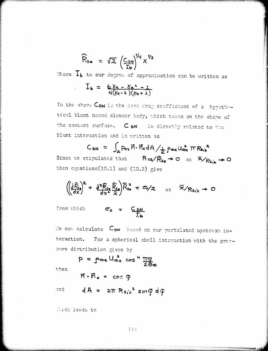
^W^raHWW^w^OP^nrwflW^TWw^^ iMLiu-^TMW^i
V/here lb to our desreo of approximation can be written as
lb = fc^- fre* ^1
In the above CON is the none dra^ coefficient of a hy^jth--
tical blunt nosed slender bod-/, which takes on the shape of
the contact surface. C t>N is directly related to the
blunt interaction and is written as
Since we stipulated that ^ csj/Rs "* O
then equations(10.1) and (10.2) give
as *i /R. CO
c^r^-^i-)^^^ X/RSl.0 ^ O
from which o-« ■= lb
'..Te now calculate CbN based on our postulated upstream in-
teraction. For a spherical shell interaction with the pres-
sure distribution given by
ien
anc
2.000
n • m x ■= cor. (^
dA - 2.Tr l^ste1 stncj c|(p
• '.ich leads to
i i j

i i'i.iji™iu]i»uij(«impiiu»wiium.iHi»i...(iiiijiJuijüijji1iiii lim. pp . m.iip »n i iibii ■ ipiiwunitiuii «WHWW ■H^CMwnMmnRmpanwmnmwiu nua
C^N = H r COS II$!!LSIH9* ^S^K» ^9*
As in a previous inteGration, we use Goo as the upper limit of
integration instead of the exact result. In this case, v/e art
further substantiated in this approximation by the fact that
near öco^^tl he contributions from the above integrand t o •bN
are near zero due to the cos 9* factor in the above.
V/ith the previously calculated values, the shock shape can
now be written as
Geo wQD vVV 1/2
Also from (15.6) we have
Res = S, /fi^lif-''"^^ . ^
V-'e are now in a position to calculate layer properties based
on these results. For the external flow wa have
V.'ith ^ v \Ks,/ /
This distribution will bo valid throughout the external layer
The density distribution is given by
114
. ■■---.;-.-,.- ^-^ ._ ■■. ^ _ ^-..^— --.. . ^- .^ .- - ^--- >.-- . .. a.^^»-,.^. :*,.=.* ^^,..—^■^.. ■ ^^^■,. ■-..■. ^„„^ ^^^^^w^ ^A, ^^^^-'i- ^' ■ ^ -i--. ■ '^ ■■■ .. - v...^ .■■.■„... .^wi^^vi^j^täiitÜM

^»^eW"IM«?™!WP!l««WW«IIW>W?«mP»WWW^»>™w»JpBiPll^^
Q0 = (l + ^*/?>)%/2.?'
The result is not strictly valid since the density is not
zero at the contact surface.
V/hen referenced to values at the shock, the results become
p./p= - Pe/fe
Te/fe
** (16.1)
= V* C^/^)(l + W4/Cp) do.2)
= HVy* ** (16.3)
For the internal flow, we have the following results:
pct = Ca/8X (l6.4)
foi = CVSX (16.5)
VCH r ^/C/^V^^^^V (l6-6) c ex>
V/hen referenced to values at the shock, the above become
pi/pe - V^ (16:7)
fl6.8)
(16.9)
»«.
** Not valid at contact surface
-— - — "— -■-— -^ -^^—"■^—^—^•-^^-—-^ .-. ^— — —.— —

7-.*MVHUiHwmiiiiiii « ■•■ P» mmti .* ■»■"•■P-^III . iu.ui tmmimm ti IIVMI /■ mw ■«■ I<<.MIWIMWI»V>II w•»•,IIJWH»»W"<«IP.« ■■■■> — ■ i -■ ■ > i*"<•■■. M >wif«-<ai «««wi^iBiHipv^i^npinBnq^nmmfOTmnpvw
The first order solution obtained thusfar from the hypersonic
small disturbance form of the Newton-Busemann approximation,
is adequate to describe layer thicknesses, pressures, and den-
sities in the far field region near the contact surface. How-
ever, due to the assumption of ^"»Ithe temperature to the
first approximation is in considerable error for "x/p .>>1.
This is because the expression for temperature, 3=" -(■&) **
gives the unrealistic result that for all ^o , ^L+las ^->1
This result is acceptable for small X/^, , where p/p is of
order one, however, for X/^l & is smaii and even for ^
near one X. << l. Ts
To obtain a more accurate value for temperature near the con-
tact surface, the unexpanded forms of the variables in terms
of iS will be retained. Referring to Cheng and Kirsch34, the
unexpanded for S' results for the 'entropy wake* are
(17.1)
J=>e= fe'Vs*^ (17.2)
The retention of the exponent, /*., in a?.1), (17.2) is justified
because the relative errors are smaller than any integral po-
wer of 6e . Applying the same reasoning to the internal la-
yer expressions, (14.3), (14.4), we obtain
V ptW
116
«iit'„v...,.r'.V:ivi, , ..- ■ ■■■' ■ '■■■■■ ■' ■■- ■■■■■-■■--■ .-.•..■■-,•.-.■ ...■■■..- ^ ,....■■.,:■. --,..,:.-^,- v ..■..--..: ■.- -..- .- ^--'t.-b-^^.:M.t.|U^ft],.t^|ll-,iV|||iM|rtini,t^'>t,irrii • f i - -■..■■■.■■.- - ' y- n t ■ ■■, ■■:.,■■ ■ ■ ...... '.■ -... :.....-.. ..,/.-./i.„ti^»J^4iUF^«AijAL'k.'i^<-<>&>vi,vV>rf.>',-',

^■^W'VTWBJPBWWWWSW^^^
Matching (17.1) to the near shock layer results (6.1) and
then combining v;ith (17.4) we obtain
plA'(fU -R«) - o-/^ This is the same form as expression (10.1) with Po replaced
by p« . To the accuracy needed for X/fe,• ^> 1 it is ade-
quate to use the formal result (10.1) which utilises po in- '/fee
stead of pc . However, for the distribution of temperature,
we use
ti
^ - fe)/ (17.5)
for both the external near the contact surface and internal
flow. This expression will give accurate values of -3=" for Is
small P/ps as well as for p/p5 near one. To be consistent,
we also use the density expression
instead of p = ps p/p^
Making use of (17.5) and (17.6) and the expression for pres-
sure (16.1) the temperature and density distributions near
the contact surface for the external flow and within the in-
ternal layer are
T = Ts (^_\
117
:
■ ■ ■ ■ ■ ■ ■ ■ - ■ ■ ■ ■ ■....-..,.,
V,T^-,l.l-'!-'".>-T^«'in.-'—"1—^T IIIMIIUWU^^ MM II W W-^u».<, .Jtflwn; n W-«. y-i.-i ^(»■^■iw.irifHf.iiB-T .fi^..
The above expressions, as well as those previously found, are
used to predict geometry and flow properties in the far field
region for typical systems of interest.
118
—^-..^--.^.■^—,- ..^ . -— .-.- ^ ....-i.-^*——.— - - ■-^■•■■^•—-^-^'-- ■■•' " r-.-..-f-.w.^l..ii,..-

!.■■■ .i.«....! -,.,,._,^.»1^,^_ ' in " iiiiiiwm™mi>^mm«mmnmrmmmmmm*mm*mmimninHtmm^mmimm*mmmmim[tmf*mwnw\liu>vi*^wiKfmi*mmit
DISCUSSION OF RESULTS
Examining the far field analytic solution, we find that an
experimental simulation of an actual flow requires matching
Sj , ife , 0», n and Rsto f the same scaling parameters used
in the.bow region simulation. If, in addition to the above,
roj/Pooe i5 matched then the bow, corner and far field geo-
metry will be simulated. For a given system with fixed am-
bient and exhaust gas composition (i.e. ^e,^' fixed) and noz-
zle conditions (i.e.,6co,n ) the flow geometry will scale as
does the bow region with Rst'0 or Tf /*. If Moo« is also as-
sumed to be fixed, then the bow, corner and far field regions
will all scale with Rs^ . Calculations of far field flow
geometry and properties have been carried out and the results
appear in figures (21) to (24). As in the bow analysis, the
far field geometry is sensitive to the exponent used in the
exhaust plume model. From figures (21) and (22) it can be ob-
served that the internal layer occupies a large fraction of the
shock layer flow. This is due to the greater amount of str-
ongly shocked, and hence lower density, gas in the internal
flow compared to that in the external flow.
As shown in figures (21) and (22), increasing 0» or *j re-
sults in the moving outward of the shock and contact surfaces.
This behavior is consistent with the results from the bow re-
gion. Also, near the contact surface, temperature, pressure,
and densityfor the internal and external flow increase for
increases in Goo or ^1
119
M --•■-——•■■——-—^ .iWwMt««„^....„ ^nmmmmm -

' —' ■■—-.w^w i mm ■»-...PM^. mmawiNuu MIUI«II i p«jvv^7pwi«i UIIIMIIIVW;« . m P«MJ nwn« ■!■«■■ «W «»-..«...-....I—*-I^I^.UP,|.IH^III IW«>I ^w^^nw^matl WIl.PliiUllpJIIJl! U MIinW^pqmpiV^R«
The effect of the internal layer flow on the external flow
pressure, density, and temperature is to maintain them at a
higher level than that created by just the bow interaction.
This can be seen from expression 15.4 in the far field analy-
sis section where the coefficient for the pressure decay
expression consists of the normal bow interaction term plus
the effect of inner layer thickness.
In figures (23) and {2U.) the detailed property distributions
across the layers are given for the same "cold" jet and actual
jet cases that were analyzed in the bow section.
Consistent with the bow region results, we find that the act-
ual jet case shown in figure (24) has a hot, low density ex-
ternal layer, which flows over a cooler and more dense inner
layer. If allowed, considerable heat transfer and mixing bet-
ween the external and internal layers would occur. The "cold"
jet case does .not exhibit as sharp a change in flow proper-
ties across the contact surface as that of the actual case.
This indicates that "cold" jet experiments must be interpreted
carefully in light of the greater mixing and heat trans-
fer effects for the actual system versus the "cold" jet simu-
lation.
120
^^.■.■■.-^uj..ij^v\L.^ttj^^fc^J<^j:<.k-i4d>!ibJ^,.^....f...J.■,-,.■_■■......ii .^.....:.,-,...., ,c.,. rjivrffrii'fä^awmiTilim'iaitBlhiiHn'liT'ii'iji

'mr*-Vt*rr**'*ir?v™rPW7rr^^ ,rvw^.»^^ ^-«.^lIMÄMIi«.!^!..! W^
CONCLUSIONS
Analytical techniques for predicting flow properties in the bow
and far field regions of an opposed hypersonic plume in a hy-
personic stream have been developed. It has been shown that
they are valid for a wide range of altitude and jet thrusts
for typical systems. The influence of the corner region flow
on the bow and far field flow predictions has been shown to be
negligible. Consequently, only a qualitative outline of the
flow processes in this region are given.
Some of the major results of the analyses and calculations
are:
1. Experimental simulation depends on the matching of
^e > *l ^0O ^ n ^ ^*io ) Fkj / pooe
2. For a given system with fixed ambient and exhaust
composition, external Mach number and nozzle con-
ditions (i.e., fixed ye,Vj,6eD,n,Mooe) the entire flow
geometry will scale with Rsieor «T
3. This analysis confirms the good accuracy of,the
Newtonian impact analysis when applied to the axi-
symmetric bow region, and suggests that the extension
of this simple technique to predict asymmetric bow
geometry might be successful.
4. The bow and far field solutions are sensitive to the
exhaust plume model exponent used and consequently
for accurate predictions of flow properties an accu-
rate plume model must be utilized.
121
... . ■ ..■.....■ ...
■.■.,.--.^,..-..-^^.,L.,,..,-J.1J....--.....-.'—----■.■^.■.^.■.■..1-.-... ^..„..-.■^■„■;.-^-.^.lJJ^.^..^^-.. A. 1iatB|ja^Ya||iiMt^|-j|^ ■;,, ,f.>........-J..,-.,.„j;...,i.,.M^:^K..; : ^■-l. --^^

rwwwPTEws^wwP'»^CT'T,r!^^ ^»•-TTiTTT^^r-^r^.^^-KT'Ti'TTTTOT^^
5. Penetration of the intercepting shock layer flow into
the internal layer is considerable. However, the
influence on the bow and far field properties is
small.
6. Good agreement is found between a calculated bow re-
gion geometry and an experimental result.
7. Calculations show that mixing and heat transfer ef-
fects between the hot external and cooler internal
layers are more pronounced in the actual case than in
the experimental "cold" jet simulation.
Ö. Increasing the primary system design parameters &oo
and &j with all other parameters fixed results in
a. The thickening of internal and external layers
in the bow and far field regions
b. An increase in radius of curvature of the con-
tact surface and thereby an increase in bluntness
for the bow region
c. An increase in the angle between the far field
external shock and free stream direction
d. A higher level of pressure density and tem-
perature both across and along the internal and
external layer flows.
■^ 0a;, is related to noaalc exit Mach number anä angle and exhaust gas conposition. For a fixed composition, increasing nozzle exit angle or decreasing exit Mach number gives in- creases in öco . Vj is related to exhaust gas composition which in general will decrease as the degrees of freedom or the complexity of the exhaust molecules increase.
122
*- ■ ■ - ■„.... .; ■....,- : , ._*_,_!__*.,**»_^—„——llrfl

— uiiinwiiKIUHIIi wmmmnwmwjumtiuu I «xipxan^nmmimi^np^a I1IJ m UIU II IPIJI.UIIIII WPWWmBOTmpa^nn^üK"""-' "»Um I W^P Uli 111 ■ 11«1I.1IHH»W»»!WWW^I
9. The effect of the internal layer on the far field
region properties is to maintain the pressure, den-
sity, and temperature of the flow at a higher level
than that which would be created by the bow region
interaction with the far field internal layer flow
absent. i
For high Reynolds' number flows the present technique may be
extended to treat mixing effects along the contact surface
by the use of boundary layer methods. Also, equilibrium chem-
istry effects may be easily incorporated into the present mo-
del through use of Ilollier charts.
Further extension of the bow layer technique to include vis-
cous chemically reacting and merged layer effects requires
considerably more effort than the above extensions. In this
regard, an advantage of the present technique over the numer-
ical technique of reference (7) is that a complete solution of
the bow region requires approximately 13 seconds on an IBII
360-65, whereas the numerical technique requires 120 seconds
on the much faster CDC 6600. This economy may prove to be
significant in extending the above techniques to be able to
predict viscous chemically reacting or merged layer bow pro-
perties where an order of magnitude increase in computational
times is expected. This makes the technique of reference (?)
uneconomical for use in parametric calculations whereas the
present technique would still fall within the practical time
limitation for these calculations.
123
■.. .■■

W^W«WIW»*J™W>J»»ä^^
REF5RE:ICES
1. Romeo, D.J. and Sterrett, J.R., "Exploratory Investiga- tion of the Effect of a Forward-Facing Jet on the Bow Shock of a Blunt Body in a Mach 6 Free Stream", NASA TN - D-1605 (1963)
2. Char-vat, A.F. and Faulmann, D., "Investigation of the Flow and Drag Due to Control Jets Discharging Upstream into a Supersonic Flow", Proceedings of the XVth Inter- national Congress, V/arszawa 1964» Vol. Ill pp. 85-114
3. Finley, P.J., "The Flow of a Jet from a Body Opposing a Supersonic Free Stream", J. Fluid Ilech., 26, pp. 337- 36Ö, (1966)
4. Cassanova, R.A. and V/u, Ying-Chu Lin, "Flow Field of a Sonic Jet Exhausting Counter to a Low-Density Supersonic Airstream", The Physics of Fluids, 12, pp. 2511-2514 (1969)
5. Smithson, H.K., Price, L.L. and VJhitfield, D.L. , "v/ind Tunnel Testin-1: of Interactions of High Altitude Rocket Plumes with the Free Stream", AEDC-TR-71-llbv, July 1971
6. Laurmann, J.A., "Elementary Mewtonian Theory for the In- teraction of Two Opposing Hypersonic Streams", Institute for Defense Analysis, Research Paper P-509, July 1969
7. Rudman, 3. and Vaglio-Laurin, R., "Flow Pafterns and Re- gimes for Retro-Plumes", Advanced Technology Laboratories, Inc., Report ATL-TR-154, January 1971
8. Hamel, B.B. and V/illis, D.R., "Kinetic Theory of Source Flow Expansion with Apolicaticn to Free Jet", The Physics of Fluids, 9, pp. 829-341, (1966)
9. Simon, G.A., "Rarefaction Effects in High-Altitude Rocket Plumes", A.I.A.A. J., 10, pp. 296-300 (1972)
10. Bush, V/.B., "On the Viscous Hypersonic Blunt Body Problem", J. Fluid Llech., 20, pp. 353-367 (1964)
11. Probstein, R.F., "Shock 7,7ave and Flow Field, Development in Hypersonic Re-entry", ARS J., 31, pp. 185-194 (1961)
12. Adams, M. and Probstein, R., "Jet Propulsion", Vol. 28, pp. 86-39, 1958
124
- ■ ■ - - — - - - .—.^..M»^«—.^ ^..^-^^-faM. -^.L».-., .v .......... . ,. ^.^ ^_ „.„..., -m nitti^iilur' — - -- --■-- iir ■■■■!

RSFEREMCSS (continued)
13. Van Dyke, Milton, "Second-Order Compressible Boundary Layer Theory with Application to Blunt Bodies in Hyoersonic Flow", Hypersonic Flow Research , Progress in Astronautics and Rocketry, Vol. '/, ed. F. R. Riddell, Academic Press, N.Y., 1962 . ' '
14. Cheng, H.K., "Recent Advances in Hypersonic Flow Research", A.I.A.A. J., 1, pp. 295-310 (1963)
15. Boynton, F.P., "Highly Underexpanded Jet Structure: Exact and Approximate Calculations", A.I.A.A. J. 5, pp. 1703-1704, (1967)
16. Ashkenas, H., and Sherman, F.S., "The Structure and Utiliza- tion of Supersonic Free Jets in Low Density V/ind Tunnels", Rarefied Gas Dynamics, Vol. II, ed. J. H. de Leeuw, Acade- mic Press, N.Y., 1966
17. Albini, F.A., "Approximate Computation of Underexpanded Jet Structure", A.I.A.A. J. 3, pp. 1535-1537, (1965)
10. Hirels, H. and Mullen, J.F., "Expansion of Gas Clouds and Hypersonic Jets Bounded by a Vacuum", A.I.A.A. J., 1, pp. 596-602, (1963)
19. Hill, J.A.F. and Habert', R.H., "Gas Dynamics of High Al- titude Missile Trails", MITHRAS Inc., Report No. MC61-13- Rl, 1963
20. Andrews, E.H., Jr., Vick, A.R. and Craidon, C.B., "Theo- retical Boundaries and Internal Characteristics of Exhaust Plumes from Three Different Supersonic Nozzles", TN j-2650, March 1965, NASA Washington, D.C.
21. Chester, ',7., "Supersonic Flow Past a Bluff Body with a De- tached Shock, Part II, Axisymmetric Body, J. Fluid Mech.. 1, pp. 490-497, (1956)
22. Freeman, N.C., "On the Theory of Hypersonic Flow Past Plane and Axially Symmetric Bluff Bodies", J. Fluid Mech., 1, pp. 366-337, (1956)
23. Cole, J.D., Perturbation Methods in Applied Mathematics. Blaisdell Publishing Co., Mass., 1968
24. Romeo, D.J. and Sterrett, J.R., "Flow Field for Sonic Jet Exhausting Counter to a Hypersonic Mainstream", A.I.A.A. J., 3, pp. 544-546, (1965)
125
---■•
^.^.—..-., —■...-.. ,

REFSREMCES (continued)
25. Chernyi, G.G., Introduction to Hypersonic Flow,Academic Press, N.Y,, 19^1
26. Jarvinen, P.O. and AdaraS; R.H., "The Effects of Retroroc- kets on the Aerodynaaic Characteristics of Conical Aero- shell Planetary Entry Vehicles", A.I.A.A. Öth Aerospace Sciences Ileetinr-,, *Iev; York, N.Y., A.I.A.A. Paper No. 70- 219, 19-21, January 1970
27. Charv.rat, A.F., "Boundary of Underexpanded Axisymmetric Jets Issuing Into Still Air", A.I.A.A. J. 2, pp. I6I-I63, (1964)
23. Latvala, E.K. and Anderson,T.P., "Studies of the Spreading of Rocket Exhaust Jets at High Altitudes", Planetary and Space Science, 4, PP' 77-91, (1961)
29. Luce, R.VJ. and Jarvinen, P.O., "An Approximate Method for Predicting Plume Sizes for Nozzle Flow into Still Air", A.I.A.A. J., 6, pp. 182-184 (1968)
30.
31.
32.
33.
34.
Hayes, V/.D. and Probstein, R.F., Hypersonic Flow Theory, Academic Press, New York, N.Y. , l^p^ ""
D'Attorre, L., "Experimental and Theoretical Studies of Underexpanded Jets Near the Mach Disc, - Appendix", Gener- al Dynamics Astronautics Report GDA-DBE-64-OO8, Febru- ary 1964
Sterrett, J.R. and Barber, J.B., "A Theoretical and Experi- mental Investigation of Secondary Jets in a Mach 6 Free Stream with Emphasis on the Structure of the Jet and Se- paration Ahead of the Jet", Separated Flows Part 2, AGARD Conference Proceedings, No. 4, May 1966
Colev J.D., "Newtonian Flow Theory for Slender Bodies", J. Aero. Science, 24, pp. 448-455, (1957)
Cheng, H.K. and Kirsch, J.VM, "On the Gas Dynamics of an Intense Explosion with an Expanding Contact Surface", J. Fluid Mech. 39, pp. 289-305, (1969)
35. Cox, H.H. and Crabtree, L.F., Elements of Hyoersonic Aero- dynamicst Academic Press, New York, N.Y., 1 -jo5, page 135
36. Mirels, H,, "Hypersonic Flow over Slender Bodies Associated with Power-Law Shocks", Advances in Aopliej MGchanics, Vol. VII, Academic Press, New Xor.c, N.Y. 19C2
126
■ - — -....- ,.,„.—-..—-..T.^..-^—u - -iiiimimi 1 ,.;...-.,..■..■ ■JJ.^..,.,^..,.-...i...J „,.;-; .■„,.■..„...

Appendix (A)
Bow Initializing Scheme
To integrate the bow region equations for points away from
the axis, we must first obtain the initial radii of curva-
tures and positions of the shocks at the axis. Writing equa-
tions (2Ö.1), (28.2), (5Ö.1) and (58.2) in the form
^ *.
ceo + bCaO ft* (1)
(2)
(3)
(4)
we develop expressions for <£t/^ and shock radii of curva-
tures R5io/f?st . The geometry which relates the internal
flow parameters to those of the external flow is illustrated
in schematic (5)
Schematic (5) i-r-A
127
— - ■UM^tMMMMiMIM --'-- ■ ..^--^-^ "-■"-^""tuaiilriaiiKilftiin'ir-rrlii

■
In the above illustration
Re - Rst Cl + Q^-ÄC^^- BCqc^e) (6)
Referring to schematic (5) we can write for
Angle matching
^t - $e + 2.(.Q.C + B,-2(ac'A)9c/Cl + ^ ■+
Pressure Matching
-0/2.
9e/^ 'C||)
(7)
(Ö)
V/e now have two equations with three unknovms 9e/$ J > ^«i ^t
Consequently, we must relax one of the parameters a;, Qe
in order to obtain a unique solution. Choosing Qi = 0 the
expressions for A (0.0, B ( <aj), C ( Oi) and D ( di) simplify
considerably.
Substituting (8) into (7) we obtain q« which also gives <pe/&l .
From these results the ratio of shock radii of curvatures at
the axis, Ks^/f^ , and the relative position of their cen-
ters must be obtained. Referring once again to schematic (5)
we have from geometry
sth frr- "(fri) - gin o^. = sioC^t z$kl Re RC J/
For small values of the angles we can write
128
...„J.^„^»„.....-...„ .. .^.^ ... ..,,...^,,....,^,I.....„.J.,:.J.J ...^.,,^..,..^J,,J.-, ,„;.,t,. _..■■,,... ,.,, , , ■^:;.^.^.J..„.,.,.. .... „v. . ..^J..^..^J-.

^ "rw^ww^rrPffw^irowipwwjr^^"^^
For the initial point, Rsft/Rsto can be obtained.
The distance between their centers is then given by
Having obtained the ratio of the radii of curvatures and
their relative positions at the axis, we then use these quan-
tities as input data to the computer program, which predicts
bow properties for regions away from the axis of symmetry.
129
■^...w,-..■-:..;..:■■
■ ■
■—--—"■" MftHjMUm ■..>.L^..-^>_-iL,iln_'.lJ. ^-fil-iMriHIM- ■L">-t"'L1Jt^"'-*'1—

i~~~~-*mmm*iwmmmm~~~ mmmnmmm, in.i luniMHMWIOTWUiiiininwHia.aiiiUHBPa ■mi ■ immmmimn^ aiiij uim ui i ■! ^H^nnwmillMPnm^lMNPWn
z o o < QC UJ
UJ
X UJ
o Z <
UJ
o o
o
130
. ^ ■■■--..— -^ — -- ^--*^ ... _- -. _.^ 1—■..._..—. .. ■ ._ .^._, ^ ■*iiäl*iim)*ia- ■ ■•■--' .^■.i^.■.■^^■^^^^'^l■-■^^^^^.-■J^Ä^llUl^■^!^■^.v.^:

HM miWIWIIUlUUIII IIH»W1«'. •'■■'-"""»•«'"■■'"" "■' 1 IJlllWI»llll].i 1IWBIII1 HMIiÄ»Wi^»i^»l 1 in Mj! i i min» w i , nv n,^^*^m^mnammmmmmmm*vm****mm
V)
UJ ÜC
o
CM
6
(*ifioi) aaniinv 131
tttek. ■,....■■ ■ - -■ -. ^..u.-^^^.^.^^. ■ ^^^^..^^^.^^^^^^^^^A^^^-i^ii^.^^^^.. ,. .* ^*i:^* ■ '.^v^^ - ■■ •»■■--•^ -.- -.^.^i.^-- — ■

^Mpr^^TT« i&mrt^mi&'&WB**^^
o
t^. o o o o o «M ♦ ♦ ♦ T W
si P
CM
• x ODO <
o Ui x o
s<
Z u. u. o o o
\
\
\
\
\
\ \
N \ a >> \ \a
x O
\
No\ \ \ \
J- (D (\J CD
Ö o
2/ (I - rX) u. d
cn CJ <
fe
^Ui q
EX
PO
ST
AN
C
o a> o o o o 5
8 2< Q5 v.
6
PLU
ME
A
NG
LE
^• gfe o cr z
30
P 9z <\j Z 3 Ö 3U.
fO
r\ 6
132
- ■ 1 IMMi fcHltfliMiMMIiillMlilMlllh it -' ^-'-" "" —■ 1ir, . ,,,

■■*^™jK!f!B<m**&***nr*!mB<*^
SOURCE MODEL CENTER
Mi",0 /j1 roo'"4
TT »627. MJO^O (9) if «313. Mflo-e.O (26) —X—TT «30.0, MQO «7.1 (2)
— tt h- — X —
H
FIG. 4 EXPERIMENTALLY OETERMWEO SHOCK AND CONTACT SURFACE LOCATIONS REFERRED TO Rsio
133
l ~^ !- ' ""

jTPspcsw^DPTWTrfYT'rfF^^ ■,Mj.ifljri--^'Pt«.-.v* .I-7TO,>W". mnw*!**B.}m*miymym^wM*..^w~w-mu*^.iHnJi,iw!»ii?iiHP^isi"^-iw.w«,(T«■'w*"-'>ü*•■■*•".■■■■' ■-■"•^i■^■■,iwwJ-^^'IJ» : ,..1 u Jiip^pi
^:
^
o m
d •^ H
N ^ <
N
c
q c* 8 =
8 ".. 2 2
N
l5
H ^ ^ > UJ Ul Ul Z (t Z I- 0.
I X
I g _J
<
DC C I
UJ QL
en
I o:
a o o o
o UJ o: QL
io 6
134
■ M ■ - --- -■ - ~-. .-— ^ — J1-^.alA>-.^.1..u..1 ^^:J1^-!.J>^.: ;.;, .,..,.., ,.„. . ,:. ;,,..w ,. ^,L^....;...:„V.U..^„^i.i.^>^..t...^. ,„„,

1 IJMI.II lULIIIIII I- ~**mmmmiim^* ' 11 i «n. »M iiiiiin iiiiiuiaimiwii.iHiMmij|i#<npmi|pn<iiiwHw.iiw " " '■' " ■ m
> o 3 fe z (/) 2 X n 1- 3 « t a:
* <—
m ^
•0 >
X N IO o o ST H
w~ w" o o c O o 15 iß O K C ->
tl <o o 2 o &
H N a: a: _i
*5 •—' a: a: <
2 2 UJ UJ o
0) z o t 0)
£ UJ
QC
in
z o o o z <
o o X en
o </>
E g O o
CO
o
135
ttfaiMwafa|»WMii>Mte> " -—-- -^-^ --J " ^- -' —

W*"■■• ■."^T™-»riij,*u.j#iA. 4*Mii>^nnn^^""WWi'TiWnWMi'W^^.'.'i.^iL^Vi<»UiJil^ip^RaR W-^fW]H(«»)!WJ»fJjww(«■.^.»»^WWAJW«"^W^OTO-'WI!MI' »MA«!-^"W.»^.1 W-•■-,««""TIT.«WT'Wl.(J,W.-W.MP!1'.ftn»»T-''JT^VTt-,JW^^J^AW'WIPBW.AiJf ISBIWilf 'V^.^W.'AUff",..M11j.|i. mi.ill ,iij .nMl ■ U.i.M«<K|M
N0liVN9VIS
Lü (T D (/) cn Lü Q: Q.
UJ o S
§ O O
o
o a: s o o
(!)
d/d
136
■ - ■ - ■■-■-- ...■. ■—--— —'-" -■ -- . ..■.,■■- (aJUtuül - .■«■-ii

^*'r*r*7?77v***vrr*r*r^!~rr^^ IW'W.'^^W.M vt^i-Mif 11,.. mpfp^ip ifi p ■ HPJ i .Li 11 H-.».-P- m i f i'i"- '* i p nipnmi
o (S z o o
to
Id
^ Lü
X O ÜJ UJ ferl
< z o 0(75
o Sou
Q. U.
O 3 ü- o </) o
00
o Ü.
5 < M
137
..jt.^...^^-^...^-^-M.1.-.^-jf.^.K.-w,..--i.:.v^. .■^■.:....^^l.t,^^^w^,t^V^^^^^a^J^J.u^^^^^^ ^-^.^t.M-l^wuJ...-i---M;.^»*j.uj-;..;,^

-TTr-rirrrtW**?*?*!**-^^ .^P^fW^n^fTW^WW^Ff^
to
5 <r
o D s 5 15 o
oc 0) (/) UJ a: a.
(/>
13 z o o
o li.
N0I1VN9VLS d/d
138
-■■-■ ■■ -"—- - -''--" aMail I MM riiriiiliiriii'riiiliilllniiiiiiriiiiiirTrtiiiiiiiliiiriMlilliliiiiiihirii -■ ■ - "■

F"^ , -ijjipuwuii»iu.,m^w«ww»iN,B|y"H*i|w
o >^?
« b O CSi ♦ « M " * c c c 1 1 1
«> 0- o ii y to 1
1 •
>-
Lü
O tu o
o CD
5 s
u.
139
— - ■..,._■■.- - , .^. ^ .-^i...—..-.^^...t^^—^.■^^-^-.— --"••—--iH«iiiiyiMdiii■ II- i i ..^-.::-,.—^I^-..^..-:-^.-.^^-,.^. iv i- -• iii' ii- ifii^iiiiH'itcntiiüi'i'iifaytln'ii

^mmmmmmmmmm mmmmmm ^mmmmmmmam
m in * in in _: <• M eo 7 CJ — — V«» -
•-.CD CD O Ö K
e CD
X b
UJ
s o CD
140
■- ■ -,-:■. .:-.^.^^^,;..;'i-, - -.-.■-.-. .^ «»ji™^^^a^^l-,uJ;.yi^,-t.L'^,>/..,*-.r.v-.J. ■-. . ,

py^~.- - ,. ,,,..,*.i.^,,«,,„„^.^v«^.,, MM.'.'■ V!.?.?T'? ^"«•A^hWWWVt«."■ ■ ■■ ^-rtl'. ';P^™i N..I 4U HH H»>.N.JJ.k,'.! (I.Im ■ '"WIT "WWH! ilfiU,»JftJIW.MiJllfl-M^ mWW^m »H MP ^WfW««ifW«W^M'.TWJfP!^,'"W,..'il^'^'-P.|'JJ-»p,!!(.? ■ *■--■T" •^^•V.T".IW»T. r.1«-*1.-^--'.'"*W«r^'Bl"!Ji■"_■-'-v«.'IJ.^ii
•
y~
*
s
s /
/
s s
• •
/ 4
/ / / / / / / /
/ f 7 ^ N C
n •
5) a 1 1 1
1
0 1
8
//
//
[/
= CM N« (0
8 ^ 2 N
0J
00 d <
Q < a:
d
d
d
8 Q>
i a: <n u rr a. UJ
I QC
Z o o ü. o
00 d d d d
5 <M
N0I1VN9VIS d/d u.
141
...i.J.- -■ ■ ,. ^>: ^..'^^. .■.^■.-■,........:..,-....^.-.i.....;.-.-^-jl.-J-'-.,.,.-..^ ,,..i,.,„^^._lLj.iA^J'J5jrt,;„J-... ■—^■-; -^■"-
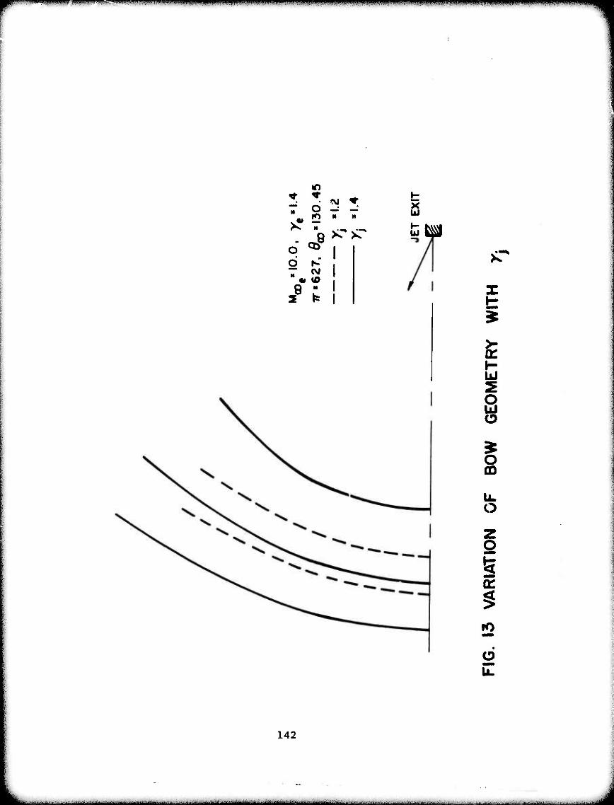
■'■ ■•," ","1 i '■ •<••"•• ■i>" ~*'^*9mmmmmfmmmmmmim*mmimmmmmmm^'>'imimmmimm MJ i immamamr^miimmt.u«mm
r ^ ♦ O - -
H
X UJ
o ^ I 8 ^ >-
t m|
8 I K £
U
s I CD
UL O
Z o i QC
rO
2
142
—^^'-'^'■*" -....■■.■■■■ ^^^^JU^^M^^^^^^^^J^^^^^,*^^^.^ u..-...^. ■ ..^ . ..^ . ■-..-... „ .^..„^^^.v^^.-—.;a-..JJ.rt,^.LL.^.^.^ -J.t..... ■tJ.. ^■. ^^.Bt.Jiaital

W "■ i .iiiiiiuiii^iiiuiJiiKitvra .imii>L<uuui ■ . t.UP unai ■■nHWiiH.piuiijnuiui> m .«Min mini«.. •!! i.u«! uiiaii.in nj. niiwui ■« '■ "i ■!■ i>igwimpnnn>rpa^m*Mvin<P<Hmw«iin"W«v«m^
/
/ 1
s
/ S / s / / 1
/ / / /
/ A / s / / / / / / •
/-t / / 7 Q
1 / v« 2 CNJ ^r
/ /
// o Q? >r >c
. 2 N" i // « <0 1
// 8 " i 2 ^ 1
1 1
CNJ
V)
SI
CD d
a.
-6-
d
CVJ
d
I
UJ QC D (/) i/> UJ o: CL
UJ
cr 3
Z o o u. o
CD
d (0 d d
Cvi
d
NOIIVNOVIS d/d
143
■'■'■*■■-• '-■■--•-'■- .A«Mfii>AkM» UüOtfÜaU^MlBltai^WUa^kHUW ■-■'■*tt"-t*'aM*>>d'**'fc^-A*-^*a-^*'**JI**'MtttMinM**t^t**i^^ - . ^ .-.^ . .f. -ii.yftll ml-i ii

.'un»-^^^'^^'''^^^.^^^^^ •"" > «. UM liMi.lii ■■* lupiiu»! i.i.Ki ■. -w; -<««■
IT * f».
c ^r . o
q UJ O
ÜJ
I CD
e en u
2 <
o z <
en <
o en
144
-~-*-~*~-~*~—~~-—~*~ MMMMMfe« -i--.. -.. - - - .~ ...- -.- ...^^j

^^awp,,'i'i^»w«'*w*i':"'iM '!n^^y'.«^.^rM mmrmmmwirf^mmmFmwmmmiimff
lO
o
♦ * r^ d) 8
v* —.^ O ^ ^ c ^
Q O K: ¥
8 — " •-. a 2 N K0
Q8 8 UJ
g o UJ
CD
£ cn z g
CD
£ in o >
Ü
3 UJ >
UJ o
6 u.
145
.■.■^■..^..■^^■...-^--„■.^^^■..>.,^.1- ..^■■.-.....-..^■„^^.^w^,..- -—- - -— - iiliiiniiimiiiiiiniiMiliilm i
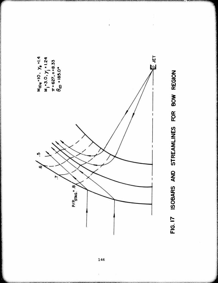
«»PWWPffHWIWIPpWWHfJWTTWJ^^
^ * -— (M ro M ro ^ H 00 •
o It
ST m
O c o
oo
4« ro (0 N
8 H u p 2 2 ^ CD
Ui
O O
i Q
< ui
o z <
Q: < CD O
6
146

"' ■■ ■ ... ..^»^..W.^^M.^-r,^--—™".----«^
o O lO 00
8 "-. " - 2 2
Ui
ÜJ
CD
Q: D
CO z o 3 GO E
5
b o
§ >
o z <
I- (?) z UJ o
s 6
147
■
■■ --- ■
■■"■..^^^.'^^«^M^WWl^^th.»4^«WW ^

' J IHUI 1IJ1U •.n.i»ll^.»li»niluiww^«»p«B»Wll I I I., IIIII.I.I.IUJI.,I.1I«I|IIIII1U »ii mMP.iwiu 11 an uaiii w WJMWJIH ■ ■ i. npi i w PiMwq
o 5 UJ cr
a: ÜJ z cr
2 6
148
Ihiii iriii------ -— - —■——■--- ■•■ ^.^^.-^ii.^^-^^»^-^^ . ^ .. — ■■^•"-- ..^.^-.i ^ ^u^l,^.^. ^ , -^..^.-..^ J...... J„^,^ L^- ■■—■-■■■.■ ...-J^.l ^ x.-^.^ H-.L.:. - , - .. .^...^-■v.^JJH

Il,l,l,,,l•" "Il1" "-" ■" ' ' -' iiiiiiinii« ii UM. miw.-.MPi jinaiu iiiwi^annni i iiiiuiiiiiiraiji» iiiiniiiiiw"«w»«w»«ü»pBwnm!wn»^w»*^»«^wTT"—w^»™«^""—«w^l«
u: bJ K
8 -: - - S N r- s
o « o .-. o oo "? 3 ^ ^ in
u: u: it #
N r>* if» « <0 O oi (\i rvi rj 6 N
— a> u> O K> K) ro ro cvi — * *
• ■ ♦ o a O < VA
n X z
I I
O
o
CJ o
a8
CO d
<o
m
K)
(\i
d
UJ
>
UJ cc D (n en u oc a.
CD
<
pa H UJ
CD
uii a: ^ en </) ui a: a. UJ a: o o
o M
o ill
o < 2
X UJ
a.0
149
Ihfa^- .„ -, ^.^ .. "w"-'":j-"- ■ ----
11 •■■u' i.»ii.i«ii.inw» limn \\ntmm*mm^^***p*nm.mmimu\^mimammmmmmwmmmmmmi mm mm
cn o o. LÜ o i2 a: (/>
i-
o o
o
o o X 0)
o -J U1'
6 u.
150
- ■— ■ - - - I iim-r'iniimMMiM

^"""•"■'W"»"'«'r»W»W!««"-?'"«""W"-'>"-™"--"W^'^»W^
Q fc (/> o Q.
(/)
o .<
o z <
CO
o UJ
a: (2 CM CM
6
o «
a:
151
-■ ■ ■■,...-.-..,
. «MMWMHMMMMMMMaaail ■ ■ -
-•- - I I !■!

'WWi»k«i|«,«VJWJSMH"u«-^.i.i»WMW
0.8
Ui V <r _i 0.6-
ul
-r
0.4
0.2
M ooes»0./e=l.4
^ = 130.45°, y. =1.4
Toj/T0e=2.0,7r=627
x/Rsio=IO
0.2 04 0.6 0.8 i.O
FIG.23 FAR FIELD PROPERTIES VS. FUNCTION
STREAM
152
■: -, -..^jf.a. ..v. i. .^^if.c* ^ I ■ ..: .....^1-...J^..--l^^... ..-:..-...-..K-^,.1.....-^.^ ^...^ ...-■-.V^:;-. ■-■:...J .J..- ... . . ..- . .. ... ., ■ ■ . ■ ■ ■ ■■...■...^— i ■ ■- ■.-.--■.:- .■ ■ , - . ■ -■ - '. -■■■■U

a:
5 -I
a: UJ
MaDe',0.>t"«4
0<3D-I85.0*,x. «1.24
To'\9mJ5, 7r«627
x/R SK> •10
0.2 0.4 0.6 0.8 1.0
FIG. 24 FAR HELD PROPERTIES VS. STREAM FUNCTION
153
———II IMI1 lllllllllMMHIltlllll—ll—IHMII1I ■- -