actuators & dampers - kele
TRANSCRIPT

ACTUATORS & DAMPERSA
CT
UA
TO
RS
&
DA
MP
ER
S
ML61xx | p. 25
GMA/GCA Series | p. 36
KAS Series | p. 28
CDRS25 Series | p. 59
LMB, NMB, AMB, | p. 11GMB Series
TS-470 Series | p. 4
Kele Carries All of the Major Manufacturers, Including Fire and Smoke Solutions.

MODEL/SERIES PAGEProducts manufactured in the United States
Products that are new to the catalog
ACTUATORS & DAMPERS
kele .com
GND Series | p. 48
KA-44 Series | p. 9
VD-1300 Series | p. 63
AC
TU
AT
OR
S
& D
AM
PE
RS
AccessoriesKLNJ-A2 — Whisker Switch . . . . . . . . . . . . . . . . . . . . . . . . . . . . . . . . . . . . . . . . .3LS45M91B11 — Whisker Switch . . . . . . . . . . . . . . . . . . . . . . . . . . . . . . . . . . . . .3TS-470 Series — Damper Position Switches . . . . . . . . . . . . . . . . . . . . . . . . . . . .4TS-475 Series — Non-Mercury Damper Position Switch . . . . . . . . . . . . . . . . . . .5TT-470 Series — Solid State Tilt Transducer for Damper / Valve Position
Feedback . . . . . . . . . . . . . . . . . . . . . . . . . . . . . . . . . . . . . . . . . . . . . . . . . . . . .6Actuator Accessories — Mechanical and Electrical Accessories . . . . . . . . . . . .7 Fire/SmokeGND, GGD Series — Fire and Smoke Damper Actuators . . . . . . . . . . . . . . . . .48MS4xxx, MS81xx Series — Fire and Smoke Damper Actuators . . . . . . . . . . . .53FSLF, FSNF, FSAF Series — Fire and Smoke Damper Actuators . . . . . . . . . .55 Non-Spring Return ActuatorsKA-44, KA-88, KA-175, KA-301 Series — Kele Revolution™ Direct Coupled
Actuators Non-spring return . . . . . . . . . . . . . . . . . . . . . . . . . . . . . . . . . . . . . .9LMB, NMB, AMB, GMB — Direct Coupled Actuators Non-Spring Return . . . . .11MN Series — Direct Coupled Actuators Non-Spring Return . . . . . . . . . . . . . . .17GBB, GDE, GEB, GIB, GLB, GAP Series — Direct Coupled Actuators Non-
Spring Return . . . . . . . . . . . . . . . . . . . . . . . . . . . . . . . . . . . . . . . . . . . . . . . .19M9100 Series — Direct Coupled Actuators Non-Spring Return . . . . . . . . . . . . .21MF4, MS4 Series — Direct Coupled Actuators Non-Spring Return . . . . . . . . . .23ML61xx, ML71xx Series — Direct Coupled Actuators Non-Spring Return . . . .25 Rectangular DampersCD40, CD50, CD60 Series — Rectangular Dampers . . . . . . . . . . . . . . . . . . . . .61VD-1300 Series — Rectangular Dampers . . . . . . . . . . . . . . . . . . . . . . . . . . . . .63 Round DampersD690 Series — Round Dampers . . . . . . . . . . . . . . . . . . . . . . . . . . . . . . . . . . . .57CDRS25 Series — Round Control Dampers . . . . . . . . . . . . . . . . . . . . . . . . . . .59 Spring Return ActuatorMEP Series — KMC Actuators . . . . . . . . . . . . . . . . . . . . . . . . . . . . . . . . . . . . . .13KAS-27, KAS-44, KAS-88, KAS-175 Series — Kele Revolution™
Direct Coupled Actuators Spring Return . . . . . . . . . . . . . . . . . . . . . . . . . . . .28TF, LF, NF, AF, EF Series — Direct Coupled Actuators Spring Return . . . . . . .30MS Series — Direct Coupled Actuators Spring Return . . . . . . . . . . . . . . . . . . .34GMA, GCA, GQD, GNP Series — Direct Coupled Actuators Spring Return . . .36M9200 Series — Direct Coupled Actuators Spring Return . . . . . . . . . . . . . . . . .39MA, MF, MS Series — Direct Coupled Actuators Spring Return . . . . . . . . . . . .41GK Series — Direct Coupled Actuators Fail-Safe . . . . . . . . . . . . . . . . . . . . . . . .43NKQ Series — Fast-Acting Fail Safe Actuators . . . . . . . . . . . . . . . . . . . . . . . . .46

WE MAKE IT EASY.
NEW!
1
ACTUATORS & DAMPERSACTUATO
RS & DAMPERS
1
kele.com 888-397-5353 USAMarch 2014
DIRECT-COUPLED ACTUATORS TORQUE AND DAMPER AREA RATINGSDIRECT COUPLED ACTUATOR CROSS REFERENCE CHART NON-SPRING RETURN
Brand Torque Supply Voltage Control Signal ModelDamperArea (ft2)
Kele 44 in-lb (5 Nm) 21-27 VAC 50/60 Hz, 24 VDC Two-position, floating KA-44-2T 6.3Honeywell 44 in-lb (5 Nm) 21-27 VAC 50/60 Hz, 24 VDC Two-position, floating MN6105A1011 6.3Johnson 35 in-lb (4 Nm) 20-30 VAC, 50/60 Hz Two-position, floating M9104-AGA-2S 5.0Johnson 53 in-lb (6 Nm) 20-30 VAC, 50/60 Hz Two-position, floating M9106-AGA-2 7.6Siemens 44 in-lb (5 Nm) 20-28 VAC, 50/60 Hz Two-position, floating GDE131.1P 6.3Schneider 35 in-lb (4 Nm) 21-28 VAC 50/60 Hz Two-position, floating MF4E-60430-100 5.0Schneider 35 in-lb (4 Nm) 21-28 VAC 50/60 Hz Two-position, floating MF41-6043 5.0Belimo 45 in-lb, (5 Nm) 20-28 VAC 50/60 Hz, 24 VDC Two-position, floating LMB24-3 6.4Kele 44 in-lb (5 Nm) 21-27 VAC 50/60 Hz, 24 VDC Prop. 0/2-10 VDC, 0/4-20 mA, two-pos., floating KA-44-M 6.3Honeywell 44 in-lb (5 Nm) 21-27 VAC 50/60 Hz, 24 VDC Prop. 0/2-10 VDC, 0/4-20 mA MN7505A2001 6.3Johnson 35 in-lb (4 Nm) 20-30 VAC, 50/60 Hz Prop. 0-10 VDC, 4-20 mA M9104-GGA-2S 5.0Johnson 53 in-lb (6 Nm) 20-30 VAC, 50/60 Hz Prop. 0-10 VDC, 4-20 mA M9106-GGA-2 7.6Siemens 44 in-lb (5 Nm) 20-28 VAC, 50/60 Hz Proportional 0 to 10 VDC GDE161.1P 6.3Schneider 35 in-lb (4 Nm) 21-28 VAC 50/60 Hz Proportional 0-10 VDC MS41-6043 5.0Belimo 45 in-lb, (5 Nm) 20-28 VAC 50/60 Hz, 24 VDC Prop. 2-10 VDC, 4-20 mA LMB24-SR 6.4Kele 88 in-lb (10 Nm) 21-27 VAC 50/60 Hz, 24 VDC Two-position, floating KA-88-2T 12.6Honeywell 88 in-lb (10 Nm) 21-27 VAC 50/60 Hz, 24 VDC Two-position, floating MN6110A1003 12.6Johnson 70 in-lb (8 Nm) 20-30 VAC, 50/60 Hz Two-position, floating M9108-AGA-2 10.0Siemens 88 in-lb (10 Nm) 20-28 VAC, 50/60 Hz Two-position, floating GLB131.1P 12.6Schneider 70 in-lb (8 Nm) 21-28 VAC 50/60 Hz Two-position, floating MF41-6083 10.0Belimo 90 in-lb (10 Nm) 20-28 VAC 50/60 Hz, 24 VDC Two-position, floating NMB24-3 12.9Kele 88 in-lb (10 Nm) 21-27 VAC 50/60 Hz, 24 VDC Prop. 0/2-10 VDC, 0/4-20 mA, two-pos., floating KA-88-M 12.6Honeywell 88 in-lb (10 Nm) 21-27 VAC 50/60 Hz, 24 VDC Prop. 0/2-10 VDC, 0/4-20 mA MN7510A2001 12.6Johnson 70 in-lb (8 Nm) 20-30 VAC, 50/60 Hz Prop. 0-10 VDC, 4-20 mA M9108-GGA-2 10.0Siemens 88 in-lb (10 Nm) 20-28 VAC, 50/60 Hz Proportional 0 to 10 VDC GLB161.1P 12.6Schneider 70 in-lb (8 Nm) 21-28 VAC 50/60 Hz Proportional 0-10 VDC MS41-6083 10.0Belimo 90 in-lb (10 Nm) 20-28 VAC 50/60 Hz, 24 VDC Prop. 2-10 VDC, 4-20 mA NMB24-SR 12.9Kele 175 in-lb (20 Nm) 21-27 VAC 50/60 Hz, 24 VDC Two-position, floating KA-175-2T 25.0Honeywell 175 in-lb (20 Nm) 21-27 VAC 50/60 Hz, 24 VDC Two-position, floating MN6120A1002 25.0Johnson 140 in-lb (16 Nm) 20-30 VAC, 50/60 Hz Two-position, floating M9116-AGA-2 20.0Siemens 132 in-lb (15 Nm) 20-28 VAC, 50/60 Hz Two-position, floating GEB131.1P 18.9Schneider 133 in-lb (15 Nm) 21-28 VAC 50/60 Hz Two-position, floating MF41-6153 19.0Belimo 180 in-lb (20 Nm) 20-28 VAC 50/60 Hz, 24 VDC Two-position, floating AMB24-3 25.7Kele 175 in-lb (20 Nm) 21-27 VAC 50/60 Hz, 24 VDC Prop. 0/2-10 VDC, 0/4-20 mA, two-pos., floating KA-175-P 25.0Honeywell 175 in-lb (20 Nm) 21-27 VAC 50/60 Hz, 24 VDC Prop. 0/2-10 VDC, 0/4-20 mA MN7220A2007 25.0Johnson 140 in-lb (16 Nm) 20-30 VAC, 50/60 Hz Prop. 0-10 VDC, 4-20 mA M9116-GGA-2 20.0Siemens 132 in-lb (15 Nm) 20-28 VAC, 50/60 Hz Proportional 0 to 10 VDC GEB161.1P 18.9Siemens 177 in-lb (20 Nm) 20-28 VAC, 50/60 Hz Proportional 0 to 10 VDC GBB161.1P 25.3Schneider 133 in-lb (15 Nm) 21-28 VAC 50/60 Hz Proportional 0/2-10 VDC MS41-6153 19.0Belimo 180 in-lb (20 Nm) 20-28 VAC 50/60 Hz, 24 VDC Prop. 2-10 VDC, 4-20 mA AMB24-SR 25.7Kele 301 in-lb (34 Nm) 21-27 VAC 50/60 Hz, 24 VDC Two-position, floating KA-301-2T 43.0Honeywell 300 in-lb (34 Nm) 21-27 VAC 50/60 Hz, 24 VDC Two-position, floating MN6134A1003 42.9Johnson 210 in-lb (24 Nm) 20-30 VAC, 50/60 Hz Two-position, floating M9124-AGA-2 30.0Johnson 280 in-lb (32 Nm) 20-30 VAC, 50/60 Hz Two-position, floating M9132-AGA-2 40.0Schneider 300 in-lb (34 Nm) 21-28 VAC 50/60 Hz Two-position, floating MF41-6343 42.9Belimo 360 in-lb (40 Nm) 20-28 VAC 50/60 Hz, 24 VDC Two-position, floating GMB24-3 51.4Kele 301 in-lb (34 Nm) 21-27 VAC 50/60 Hz, 24 VDC Prop. 0/2-10 VDC, 0/4-20 mA, two-pos., floating KA-301-P 43.0Honeywell 300 in-lb (34 Nm) 21-27 VAC 50/60 Hz, 24 VDC Prop. 0/2-10 VDC, 0/4-20 mA MN7234A2008 42.9Johnson 210 in-lb (24 Nm) 20-30 VAC, 50/60 Hz Prop. 0-10 VDC, 4-20 mA M9124-GGA-2 30.0Johnson 280 in-lb (32 Nm) 20-30 VAC, 50/60 Hz Prop. 0-10 VDC, 4-20 mA M9132-GGA-2 40.0Siemens 310 in-lb (35 Nm) 20-28 VAC, 50/60 Hz Proportional 0 to 10 VDC GIB161.1P 44.3Schneider 300 in-lb (34 Nm) 21-28 VAC 50/60 Hz Prop. 2-10 VDC, 4-20 mA MS41-6343 42.9Belimo 360 in-lb (40 Nm) 20-28 VAC 50/60 Hz, 24 VDC Prop. 2-10 VDC, 4-20 mA GMB24-SR 51.4
*Maximum damper area assuming 7 in-lb/sq . ft damper torque
WHEN YOU NEED IT RIGHT, RIGHT NOW, CALL KELE.
NEW!ACTUATORS & DAMPERS
2
NEW!AC
TUAT
ORS
& D
AMPE
RS
1
kele.com888-397-5353 USA March 2014
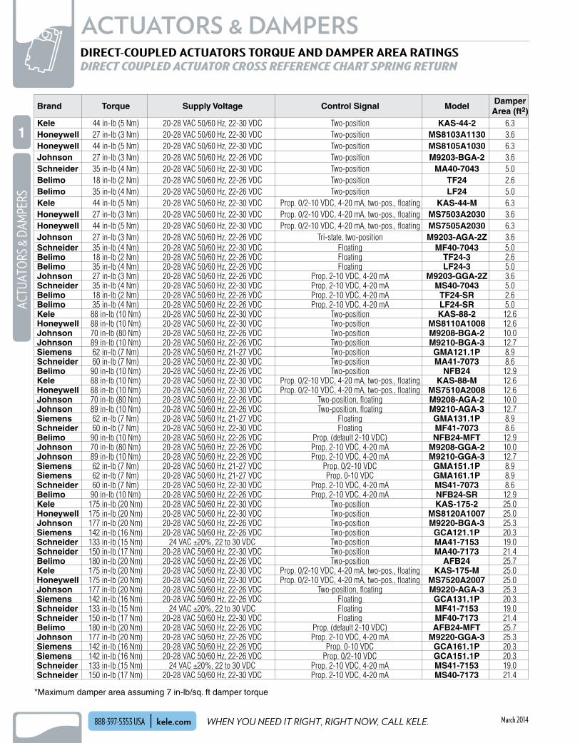
*Maximum damper area assuming 7 in-lb/sq . ft damper torque
DIRECT-COUPLED ACTUATORS TORQUE AND DAMPER AREA RATINGSDIRECT COUPLED ACTUATOR CROSS REFERENCE CHART SPRING RETURN
Brand Torque Supply Voltage Control Signal ModelDamperArea (ft2)
Kele 44 in-lb (5 Nm) 20-28 VAC 50/60 Hz, 22-30 VDC Two-position KAS-44-2 6.3Honeywell 27 in-lb (3 Nm) 20-28 VAC 50/60 Hz, 22-30 VDC Two-position MS8103A1130 3.6Honeywell 44 in-lb (5 Nm) 20-28 VAC 50/60 Hz, 22-30 VDC Two-position MS8105A1030 6.3Johnson 27 in-lb (3 Nm) 20-28 VAC 50/60 Hz, 22-26 VDC Two-position M9203-BGA-2 3.6Schneider 35 in-lb (4 Nm) 20-28 VAC 50/60 Hz, 22-30 VDC Two-position MA40-7043 5.0Belimo 18 in-lb (2 Nm) 20-28 VAC 50/60 Hz, 22-26 VDC Two-position TF24 2.6Belimo 35 in-lb (4 Nm) 20-28 VAC 50/60 Hz, 22-26 VDC Two-position LF24 5.0Kele 44 in-lb (5 Nm) 20-28 VAC 50/60 Hz, 22-30 VDC Prop. 0/2-10 VDC, 4-20 mA, two-pos., floating KAS-44-M 6.3Honeywell 27 in-lb (3 Nm) 20-28 VAC 50/60 Hz, 22-30 VDC Prop. 0/2-10 VDC, 4-20 mA, two-pos., floating MS7503A2030 3.6Honeywell 44 in-lb (5 Nm) 20-28 VAC 50/60 Hz, 22-30 VDC Prop. 0/2-10 VDC, 4-20 mA, two-pos., floating MS7505A2030 6.3Johnson 27 in-lb (3 Nm) 20-28 VAC 50/60 Hz, 22-26 VDC Tri-state, two-position M9203-AGA-2Z 3.6Schneider 35 in-lb (4 Nm) 20-28 VAC 50/60 Hz, 22-30 VDC Floating MF40-7043 5.0Belimo 18 in-lb (2 Nm) 20-28 VAC 50/60 Hz, 22-26 VDC Floating TF24-3 2.6Belimo 35 in-lb (4 Nm) 20-28 VAC 50/60 Hz, 22-26 VDC Floating LF24-3 5.0Johnson 27 in-lb (3 Nm) 20-28 VAC 50/60 Hz, 22-26 VDC Prop. 2-10 VDC, 4-20 mA M9203-GGA-2Z 3.6Schneider 35 in-lb (4 Nm) 20-28 VAC 50/60 Hz, 22-30 VDC Prop. 2-10 VDC, 4-20 mA MS40-7043 5.0Belimo 18 in-lb (2 Nm) 20-28 VAC 50/60 Hz, 22-26 VDC Prop. 2-10 VDC, 4-20 mA TF24-SR 2.6Belimo 35 in-lb (4 Nm) 20-28 VAC 50/60 Hz, 22-26 VDC Prop. 2-10 VDC, 4-20 mA LF24-SR 5.0Kele 88 in-lb (10 Nm) 20-28 VAC 50/60 Hz, 22-30 VDC Two-position KAS-88-2 12.6Honeywell 88 in-lb (10 Nm) 20-28 VAC 50/60 Hz, 22-30 VDC Two-position MS8110A1008 12.6Johnson 70 in-lb (80 Nm) 20-28 VAC 50/60 Hz, 22-26 VDC Two-position M9208-BGA-2 10.0Johnson 89 in-lb (10 Nm) 20-28 VAC 50/60 Hz, 22-26 VDC Two-position M9210-BGA-3 12.7Siemens 62 in-lb (7 Nm) 20-28 VAC 50/60 Hz, 21-27 VDC Two-position GMA121.1P 8.9Schneider 60 in-lb (7 Nm) 20-28 VAC 50/60 Hz, 22-30 VDC Two-position MA41-7073 8.6Belimo 90 in-lb (10 Nm) 20-28 VAC 50/60 Hz, 22-26 VDC Two-position NFB24 12.9Kele 88 in-lb (10 Nm) 20-28 VAC 50/60 Hz, 22-30 VDC Prop. 0/2-10 VDC, 4-20 mA, two-pos., floating KAS-88-M 12.6Honeywell 88 in-lb (10 Nm) 20-28 VAC 50/60 Hz, 22-30 VDC Prop. 0/2-10 VDC, 4-20 mA, two-pos., floating MS7510A2008 12.6Johnson 70 in-lb (80 Nm) 20-28 VAC 50/60 Hz, 22-26 VDC Two-position, floating M9208-AGA-2 10.0Johnson 89 in-lb (10 Nm) 20-28 VAC 50/60 Hz, 22-26 VDC Two-position, floating M9210-AGA-3 12.7Siemens 62 in-lb (7 Nm) 20-28 VAC 50/60 Hz, 21-27 VDC Floating GMA131.1P 8.9Schneider 60 in-lb (7 Nm) 20-28 VAC 50/60 Hz, 22-30 VDC Floating MF41-7073 8.6Belimo 90 in-lb (10 Nm) 20-28 VAC 50/60 Hz, 22-26 VDC Prop. (default 2-10 VDC) NFB24-MFT 12.9Johnson 70 in-lb (80 Nm) 20-28 VAC 50/60 Hz, 22-26 VDC Prop. 2-10 VDC, 4-20 mA M9208-GGA-2 10.0Johnson 89 in-lb (10 Nm) 20-28 VAC 50/60 Hz, 22-26 VDC Prop. 2-10 VDC, 4-20 mA M9210-GGA-3 12.7Siemens 62 in-lb (7 Nm) 20-28 VAC 50/60 Hz, 21-27 VDC Prop. 0/2-10 VDC GMA151.1P 8.9Siemens 62 in-lb (7 Nm) 20-28 VAC 50/60 Hz, 21-27 VDC Prop. 0-10 VDC GMA161.1P 8.9Schneider 60 in-lb (7 Nm) 20-28 VAC 50/60 Hz, 22-30 VDC Prop. 2-10 VDC, 4-20 mA MS41-7073 8.6Belimo 90 in-lb (10 Nm) 20-28 VAC 50/60 Hz, 22-26 VDC Prop. 2-10 VDC, 4-20 mA NFB24-SR 12.9Kele 175 in-lb (20 Nm) 20-28 VAC 50/60 Hz, 22-30 VDC Two-position KAS-175-2 25.0Honeywell 175 in-lb (20 Nm) 20-28 VAC 50/60 Hz, 22-30 VDC Two-position MS8120A1007 25.0Johnson 177 in-lb (20 Nm) 20-28 VAC 50/60 Hz, 22-26 VDC Two-position M9220-BGA-3 25.3Siemens 142 in-lb (16 Nm) 20-28 VAC 50/60 Hz, 22-26 VDC Two-position GCA121.1P 20.3Schneider 133 in-lb (15 Nm) 24 VAC ±20%, 22 to 30 VDC Two-position MA41-7153 19.0Schneider 150 in-lb (17 Nm) 20-28 VAC 50/60 Hz, 22-30 VDC Two-position MA40-7173 21.4Belimo 180 in-lb (20 Nm) 20-28 VAC 50/60 Hz, 22-26 VDC Two-position AFB24 25.7Kele 175 in-lb (20 Nm) 20-28 VAC 50/60 Hz, 22-30 VDC Prop. 0/2-10 VDC, 4-20 mA, two-pos., floating KAS-175-M 25.0Honeywell 175 in-lb (20 Nm) 20-28 VAC 50/60 Hz, 22-30 VDC Prop. 0/2-10 VDC, 4-20 mA, two-pos., floating MS7520A2007 25.0Johnson 177 in-lb (20 Nm) 20-28 VAC 50/60 Hz, 22-26 VDC Two-position, floating M9220-AGA-3 25.3Siemens 142 in-lb (16 Nm) 20-28 VAC 50/60 Hz, 22-26 VDC Floating GCA131.1P 20.3Schneider 133 in-lb (15 Nm) 24 VAC ±20%, 22 to 30 VDC Floating MF41-7153 19.0Schneider 150 in-lb (17 Nm) 20-28 VAC 50/60 Hz, 22-30 VDC Floating MF40-7173 21.4Belimo 180 in-lb (20 Nm) 20-28 VAC 50/60 Hz, 22-26 VDC Prop. (default 2-10 VDC) AFB24-MFT 25.7Johnson 177 in-lb (20 Nm) 20-28 VAC 50/60 Hz, 22-26 VDC Prop. 2-10 VDC, 4-20 mA M9220-GGA-3 25.3Siemens 142 in-lb (16 Nm) 20-28 VAC 50/60 Hz, 22-26 VDC Prop. 0-10 VDC GCA161.1P 20.3Siemens 142 in-lb (16 Nm) 20-28 VAC 50/60 Hz, 22-26 VDC Prop. 0/2-10 VDC GCA151.1P 20.3Schneider 133 in-lb (15 Nm) 24 VAC ±20%, 22 to 30 VDC Prop. 2-10 VDC, 4-20 mA MS41-7153 19.0Schneider 150 in-lb (17 Nm) 20-28 VAC 50/60 Hz, 22-30 VDC Prop. 2-10 VDC, 4-20 mA MS40-7173 21.4

WE MAKE IT EASY.
NEW!
3
ACTUATORS & DAMPERSACTUATO
RS & DAMPERS
1
kele.com 888-397-5353 USAMarch 2014
Wiring Terminations Screw terminalsConduit Connection 1/2" NPTContact Rating 10A @ 24 VAC, 10A @ 120 VAC,
6A @ 24 VDCContact Arrangement 1 N .O . and 1 N .C .Switch Angle 15° make, 6° resetOperating Temperature -13° to 131°F (-25° to 55°C)Dimensions 8 .0"H x 1 .6"W x 1 .7"D (20 x 4 .0 x 4 .2 cm)Weight 0 .5 lb (0 .2 kg)Enclosure Rating IP67Approvals CE, cUL recognized, NRNT8 .
E117960Warranty 1 year
Wiring Terminations Screw terminalsConduit Connection 1/2" NPTContact Rating 10A @ 24 VAC, 5A @ 120 VAC,
2 .8A @ 24 VDCContact Arrangement 1 N .O . and 1 N .C .Switch Angle 14° make, 6° resetOperating Temperature -13° to 158°F (-25° to 70°C)Dimensions 7 .9"H x 1 .6"W x 1 .8"D
(20 x 4 .0 x 4 .5 cm)Weight 0 .5 lb (0 .2 kg)Enclosure Rating NEMA 4XApprovals CE, UL Listed, CSAWarranty 1 year
DESCRIPTIONThe KLNJ-A2 whisker switch is a high-quality, multi-directional contact switch with a plastic coated spring-rod whisker . It is perfect for sensing damper blade position and can be used to provide position status of valve linkages or other mechanical devices .
FEATURES
• Plastic coated spring-rod whisker for long life• Captive wiring cover screws to save time• Heavy duty 10A @ 120 VAC contacts
DIMENSIONS
WHISKER SWITCHKLNJ-A2
SPECIFICATIONS
KLNJ-A2
ORDERING INFORMATION
MODEL DESCRIPTIONKLNJ-A2 Whisker switch with coated spring-rod and 10A @
120 VAC contacts
M6x15
1.7" (4.2)
0.25" (0.65)
5.5
"(1
4.0)
2.3
" (
5.9)
1.2" (3.0) 1.6" (4.0)
.20" (.52)
8.0
"(2
0.3)
1.1" (2.9)
in (cm)
DESCRIPTIONThe LS45M91B11 whisker switch is a multidirectional, metal limit switch . This spring rod whisker version allows flexibility when applying to damper, valve, and other HVAC applications that need position sensing .
WHISKER SWITCHLS45M91B11
SPECIFICATIONS
LS45M91B11
0.05 Ø(0.13)
0.275 Ø(0.7)
0.63(1.60)
5.12 (130)
7.87 (200)
3.15(8.0)
1.58(4.0)
1.77(4.5)
ORDERING INFORMATION
MODEL DESCRIPTIONLS45M91B11 Whisker switch with steel spring-rod and 5A @
120 VAC contacts
DIMENSIONS
in (cm)

WHEN YOU NEED IT RIGHT, RIGHT NOW, CALL KELE.
NEW!ACTUATORS & DAMPERS
4
NEW!AC
TUAT
ORS
& D
AMPE
RS
1
kele.com888-397-5353 USA March 2014
Wiring TS(1)-470 3' length, AWG 18, 3-conductor
cable; green = common, black = N .C ., white = N .O .
TS(1)-470-2 3' length, AWG 18, two 3-conductor cables; green = common, black = N .C ., white = N .O .
TS(1)-470-P 3' length, plenum AWG 18, 3-conductor cable; black = common, blue = N .C ., red = N .O .
Switch Type Encapsulated mercury switch, contains 0 .03 cc mercury
Contact Rating Non-plenum SPDT; 2A @ 120 VAC, 1A @ 240 VAC -P models SPDT; 1A @ 120 VAC, 240 VACSwitch Angle Makes at 15° below horizontalOperating Temperature -30° to 130°F (-34° to 54°C)Dimensions TS- 1 .4"H x 1 .0"W x 4 .4"L (3 .6 x 2 .5 x 11 .1 cm) TS1- 1 .5"H x 1 .8"W x 5 .5"L (3 .8 x 4 .5 x 14 .0 cm)Weight TS- 0 .46 lb (0 .21 kg) TS1- 0 .8 lb (0 .36 kg)Mounting TS- 1/2" (1 .3 cm) damper shaft TS1- 1" (2 .5 cm) damper shaftWarranty 1 year
DAMPER POSITION SWITCHESTS-470 SERIES
1/20 .5 dia(1 .27)
1/24 .375
(11 .11)
Cord 3'(91 .4)
TS
-470
in(cm)
11 .0 dia(2 .54)
15 .5
(13 .97)
1/21 .0
(2 .54)
11 .75
(4 .45)
DESCRIPTIONThe TS-470 Series damper position switches consist of an encapsulated mercury switch mounted on a 1/2" (1 .3 cm) damper shaft crank arm . The TS1-470 Series includes the same switch, mounted on a 1" (2 .5 cm) crank arm . They are mounted on a horizontal damper shaft to provide opened/closed indication . Switch contacts are normal when the cable end of the switch is horizontal or above, and makes when the cable end drops more than 15° below horizontal .
FEATURES
• Easy to install• Easily adjustable
WIRING / DIMENSIONS
SPECIFICATIONS
TS-470-2
ORDERING INFORMATION
MODEL DESCRIPTIONTS-470 Damper position switch with SPDT switch, for 1/2" shaftTS-470-2 Damper position switch with two SPDT switches, for 1/2" shaftTS-470-P Damper position switch with SPDT switch, for 1/2" shaft, stainless steel housing, and plenum-rated cableTS1-470 Damper position switch with SPDT switch, for 1" shaftTS1-470-2 Damper position switch with two SPDT switches, for 1" shaftTS1-470-P Damper position switch with SPDT switch, for 1" shaft, stainless steel housing and plenum-rated cable
TS1-470
RELATED PRODUCTS PAGEKLNJ-A2 Whisker switch with coated spring-rod and 10A @ 120 VAC contacts 3LS45M91B11 Whisker switch with steel spring-rod and 5A @ 120 VAC contacts 3TS-475 Non-mercury damper position switch, SPDT, for 1/2" damper shaft 5TT-470 Tilt transducer with 1/2-in crank arm, 4-20 mA loop powered 6TT1-470 Tilt transducer with 1-in crank arm 6

WE MAKE IT EASY.
NEW!
5
ACTUATORS & DAMPERSACTUATO
RS & DAMPERS
1
kele.com 888-397-5353 USAMarch 2014
Wiring 3' length, AWG 18, 3-conductor plenum-rated cable; black = common, white = N .C ., red = N .O .
Switch Type Mechanical roller ball, SPDTContact Rating 5A @ 120/250 VACSwitch Angle N .O . makes at 20° above
horizontal, breaks at 15° below horizontal
Operating Temperature -30° to 130°F (-34° to 54°C)Dimensions TS- 1 .5"H x 1 .5"W x 4 .4"L (3 .8 x 3 .8 x 11 .1 cm) TS1- 1 .8"H x 1 .5"W x 5 .5"L (4 .5 x 3 .8 x 14 .0 cm)Weight TS- 0 .4 lb (0 .2 kg) TS1- 0 .7 lb (0 .3 kg)Mounting TS- 1/2" (1 .3 cm) damper shaft TS1- 1" (2 .5 cm) damper shaftEnclosure Rating UL 94V-0 flammability ratingWarranty 1 year
DESCRIPTIONThe TS-475 Series damper position switches use a roller ball and mechanical switch to provide open/closed damper position status . The TS-475 Series offers a non-mercury alternative for applications and for projects which do not allow mercury .
NON-MERCURY DAMPER POSITION SWITCHTS-475 SERIES
SPECIFICATIONS
ORDERING INFORMATION
MODEL DESCRIPTIONTS-475 Non-mercury damper position switch, SPDT,
for 1/2" damper shaftTS1-475 Non-mercury damper position switch, SPDT,
for 1" damper shaft
TS-475

WHEN YOU NEED IT RIGHT, RIGHT NOW, CALL KELE.
NEW!ACTUATORS & DAMPERS
6
NEW!AC
TUAT
ORS
& D
AMPE
RS
1
kele.com888-397-5353 USA March 2014
Supply Voltage 9 to 40 VDCWiring 30" plenum-rated cable, 2-conductor 16
AWG unshieldedSensor Measurement Range
Programmable from ±10° to 360° rotation
Sensing Technology Solid state orientation sensorSignal Output 4-20 mA, 2-wire loop poweredOutput Resolution 0 .8 mA @ 90° rotation, 0 .2 mA @ 360°
rotation, ±0 .1 mAMaximum Output Impedance
1000Ω @ 24 VDCLamps Red LED for programmingOperating Temperature -20° to 150°F (-29° to 66°C)Dimensions TT-470 1 .4"H x 1 .0"W x 4 .4" L (3 .4 x 2 .5 x 11 .1 cm) TT1-470 1 .4"H x 1 .8"W x 5 .5" L (3 .4 x 4 .4 x 13 .9 cm)Weight TT-470 0 .5 lb (0 .2 kg) TT1-470 0 .8 lb (0 .4 kg)Installation TT-470 1/2" round shaft TT1-470 1" round shaftEnclosure Rating Indoors only, not suitable for outdoor
installationRoHS Statement YesWarranty 1 year
SOLID STATE TILT TRANSDUCER FOR DAMPER/VALVE POSITION FEEDBACKTT-470 SERIES
DESCRIPTIONThe TT-470 Series solid state tilt transducer is a programmable, 2-wire, 4-20 mA loop-powered device specifically designed to provide positive feedback of damper or valve position to a building automation system . The transducer is quickly and easily field programmed, using an integral pushbutton, to span any shaft rotational range between 10° and 360° (one full rotation) .The TT-470 contains no mercury or other hazardous substances and meets or exceeds all current RoHS environmental standards . The transducer includes an integral crankarm style mounting bracket and is available in 2 models; the TT-470 fits a 1/2" shaft and the TT1-470 fits a 1" shaft . The transducer must be mounted on a horizontal shaft, typically a damper shaft or a globe valve linkage shaft (for example the Honeywell Q5020 linkage) .
WIRING
DIMENSIONSSPECIFICATIONS
TT-470
ORDERING INFORMATION
MODEL DESCRIPTION TT-470 Tilt transducer with 1/2-in crank arm TT1-470 Tilt transducer with 1-in crank arm
TT-4700 .5 dia(1 .2)
TT-4704 .375(11 .1)
Cable 30"(76)
TT-470
in(cm) TT1-470
1 .0 dia(2 .5)
TT1-4705 .5
(13 .9)
TT-4701 .0 (2 .5)
TT1-4701 .75 (4 .4)
9-40 VDCPower Supply
30" Cable
4-20 mA Signal
+ –LED
Black
Red ±
Note: Transducer must be oriented in the snap-in clip as shown in the drawing; the TT-470 text must be visible .
Note: The calibration button is near the LED, concealed under the flexible plastic end cap . DO NOT REMOVE THE END CAP .
RELATED PRODUCTS PAGEDCP-1.5-W Power supply, 24 VAC IN to 24 VDC OUT 995

WE MAKE IT EASY.
NEW!
7
ACTUATORS & DAMPERSACTUATO
RS & DAMPERS
1
kele.com 888-397-5353 USAMarch 2014
MECHANICAL AND ELECTRICAL ACCESSORIESACTUATOR ACCESSORIES
ESK050-K
AV10-18-K
ZG-NMSA-1-K
DMPR-KC008DMPR-KC003 (shaft only)
205830A
KC-1405L-K
ZS-100 ZS-150
ZG-DC1-KDMPR-KC054
ZG-DC2-K
DMPR-KC005-K
BJ-809-K KG8-K
Model Description
DAMPER ACTUATOR WEATHER SHIELDS
ZS-100 Galvanized weather shield for Belimo AFB/NFB/LF/TF/GMB/AMB/NMB/LMB
ZS-150 Polycarbonate weather shield for Belimo AFB/NFB/LF/TF/GMB/AMB/NMB/LMB
DAMPER SHAFT CRANK ARMS
KH6-K Crank arm for 3/4" shaft, 3-1/2" length, use with BJ-809-K ball joint
KH8-K Crank arm for 3/4" shaft, 3-1/2" length, use with KG8-K ball joint
CA-1 Crank arm for 1" shaft, 3-1/2" length, use with BJ-809-K ball joint
205830A Crank arm/ball joint kit for KA-44, KA-88 actuators
KC1403S-K Crank arm for 3/8" shaft, 2-7/8" length, use with BJ-809-K ball joint
KC1405L-K Crank arm for 1/2" shaft, 4-3/4" length, use with BJ-809-K ball joint
BALL JOINTS
BJ-809-K Ball joint, straight, use with 5/16" diameter pushrod
KG8-K Ball joint, 90° angle, use with 5/16" diameter pushrod
DAMPER BLADE CRANK ARMS
ZG-DC1-K Universal damper blade crank arm, 3-1/2" length
ZG-DC2-K Universal damper blade crank arm, 6" length
DMPR-KC054 Damper blade crank arm for JCI CD1300 dampers
SHAFT EXTENSIONS
AV10-18-K Shaft extension for 3/8" to 9/16" diameter shafts, 9-1/2" length
ZG-NMSA-1-K Shaft extension for 1/2" diameter shaft, 2" length
DMPR-KC008 Shaft extension for JCI damper square shaft, 7" length
DMPR-KC005-K Shaft extension for 1/2" shafts, 4 5/8" length w/coupler
ESK050-K Ruskin damper shaft extension kit
DMPR-KC003 Shaft extension for 1/2" shafts, 7" length
KH8-K
KH6-K CA-1
KC-1403S-K

WHEN YOU NEED IT RIGHT, RIGHT NOW, CALL KELE.
NEW!ACTUATORS & DAMPERS
8
NEW!AC
TUAT
ORS
& D
AMPE
RS
1
kele.com888-397-5353 USA March 2014
Model Description
PUSH RODS
SGA24 Remote control dial, proportional, surface mount
PR-24 5/16" dia. 24" (.61m) length push rod
PR-48 5/16" dia., 48" (1.2m) length push rod
FLOOR MOUNT BRACKETS
50001194-001 Universal surface mount bracket with crank arm and 1/2" shaft
ZG-103 Right angle horizontal mounting bracket for Belimo GMB, NMB, AMB
ZG-104 Right angle vertical mounting bracket for Belimo GMB, NMB, AMB
ZG-107 Floor mounting bracket, horizontal, for AF actuators
ZG-108 Floor mounting bracket, vertical, for AF actuators
ZG-112 Floor mount bracket, vertical, for LF actuators
DAMPER MOUNT BRACKETS
ZG-100 Right angle mounting bracket for AFB/NFB and AMB/GMB actuators
ZG-101 Right angle floor mount bracket for AFB/NFB and AMB/GMB actuators
ZG-102 Tandem actuator mounting bracket for AF/AFB/GMB actuators
DMPR-KC255 Internal-mount bracket for JCI M9000 actuators
POWER AND SIGNAL ACCESSORIES
ZG-R01 500Ω, 1/2W, 1% resistor
691-K0A Control transformer, 120:24 VAC, 40 VA, Class 2
691-U100 Class 2 control transformer, 120:24 VAC, 96 VA
SGF24 Remote control dial, proportional, flush mount
MECHANICAL AND ELECTRICAL ACCESSORIESACTUATOR ACCESSORIES
DMPR-KC255
50001194-001
SGA24SGF24
ZG-R01
691-KOA691-U100
ZG-107
ZG-108
ZG-112
ZG-103
ZG-104
ZG-101
ZG-100ZG-102
PR-24
PR-48

WE MAKE IT EASY.
NEW!
9
ACTUATORS & DAMPERSACTUATO
RS & DAMPERS
1
kele.com 888-397-5353 USAMarch 2014
Supply Voltage 21-27 VAC 50/60 Hz, 24 VDC (VAC only for KA-175-2T, KA-301-2T)
Motor Synchronous with magnetic clutch (2-pos, floating), Brushless DC (proportional)
Wiring Enclosed terminalsAction Switch selectable direct/reverse
actingRotation 95° ± 3°Drive Time 95 seconds @ 60HzManual Override Disengage button
Noise -44, -88 <35 db @ 3' (1m) -175, -301 <40 db @ 3' (1m)Resolution 400 stepsLife Expectancy 60,000 cycles, 1 .5 million repositionsOperating Temperature -5° to 140°F (-20° to 60°C)Operating Humidity 5 to 95% RHApprovals cULus, CE, C-tick, plenum rated,
E4436/E179109Warranty 5 years
KELE REVOLUTION™ DIRECT COUPLED ACTUATORS NON-SPRING RETURNKA-44, KA-88, KA-175, KA-301 SERIES
DESCRIPTION
The Kele Revolution™ KA-44, KA-88, KA-175, and KA-301 Series actuators are designed and tested to provide reliable non-spring return control for dampers and valves . They are powered by 24 VAC/VDC and accept tri-state/two-position and proportional control signals .
FEATURES
• Switchable drive direction • Service/Off switch (tri-state/two-position models) • Auto-adapt switch (proportional models) • Manual override • Self-centering, reversible hub • Adjustable mechanical rotation stops • Dual SPDT auxiliary switches available• 60,000 cycles nominal
COMMON SPECIFICATIONS
KA-175-P(KA-301 Higher torque)
KA-44-M(KA-88 Higher torque)
INDIVIDUAL SPECIFICATIONS
Model TorqueSupply
VAControl Signal Input Impedance Feedback
Auxiliary Switch
KA-44-2T 44 in-lb (5 Nm) 5.0 VA Two-position, floating None None
KA-44-M 44 in-lb (5 Nm) 5.0 VAProp. 0/2-10 VDC, 0/4-20 mA,
two-pos., floating100 kΩ @ 0/2-10 VDC; 500Ω @ 4-20 mA 0/2-10 VDC None
KA-88-2T 88 in-lb (10 Nm) 5.0 VA Two-position, floating None None
KA-88-M 88 in-lb (10 Nm) 5.0 VAProp. 0/2-10 VDC, 0/4-20 mA,
two-pos., floating100 kΩ @ 0/2-10 VDC; 500Ω @ 4-20 mA 0/2-10 VDC None
KA-175-2T 175 in-lb (20 Nm) 6.0 VA Two-position, floating None SW2 accessory
KA-175-P 175 in-lb (20 Nm) 6.0 VAProp. 0/2-10 VDC, 0/4-20 mA,
two-pos., floating100 kΩ @ 0/2-10 VDC; 500Ω @ 4-20 mA 0/2-10 VDC SW2 accessory
KA-301-2T 301 in-lb (34 Nm) 9.0 VA Two-position, floating None SW2 accessory
KA-301-P 301 in-lb (34 Nm) 8.0 VAProp. 0/2-10 VDC, 0/4-20 mA,
two-pos., floating100 kΩ @ 0/2-10 VDC; 500Ω @ 4-20 mA 0/2-10 VDC SW2 accessory

WHEN YOU NEED IT RIGHT, RIGHT NOW, CALL KELE.
NEW!ACTUATORS & DAMPERS
10
NEW!AC
TUAT
ORS
& D
AMPE
RS
1
kele.com888-397-5353 USA March 2014
54
123
0/2-10 VDC Feedback
0/2-10 VDC or0/4-20 mA,* 500Ω resistor
S1S2S3S4S5S6
CN.C.N.O.CN.C.N.O.
234
234
KA-44-2T, KA-88-2T, KA-175-2T, KA-301-2TTwo-position Control
KA-44-M, KA-88-M, KA-175-P, KA-301-PProportional Control
0 or 2-10 VDC / 0 or 4-20 mA Signal(500Ω resistor required)
SW2 Auxiliary Switch Kit
KA-44-2T, KA-88-2T, KA-44-M,KA-88-M, KA-175-2T, KA-301-2T
Floating Control
24 VAC/VDC
24 VAC/VDC
24 VAC/VDC
Service/O
Dir
Re v
Control Switch
Service/O
Dir
Re v
Control Switch
Service used for manual adjust
Service used for manual adjustService used for manual adjust
DirService/O Rev
2. . . 10 V0. . . 10 V
10. . . 0 V10. . . 2 V
CCW switch
CW switch
Switch ratings: Adjustable between 5 and 85degrees, 24 VAC/VDC, 5A resistive, 3A inductive
Floatingcontroller
WIRING
KELE REVOLUTION™ DIRECT COUPLED ACTUATORS NON-SPRING RETURNKA-44, KA-88, KA-175, KA-301 SERIES
ORDERING INFORMATION
MODEL DESCRIPTIONKA-44-2T Non-spring return, 44 in-lb (5 Nm), two-position or tri-state (floating) controlKA-44-M Non-spring return, 44 in-lb (5 Nm), proportional, two-position or tri-state (floating) controlKA-88-2T Non-spring return, 88 in-lb (10 Nm), two-position or tri-state (floating) controlKA-88-M Non-spring return, 88 in-lb (10 Nm), proportional, two-position or tri-state (floating) controlKA-175-2T Non-spring return, 175 in-lb (20 Nm), two-position or tri-state (floating) controlKA-175-P Non-spring return, 175 in-lb (20 Nm), proportional, two-position or tri-state (floating) controlKA-301-2T Non-spring return, 301 in-lb (34 Nm), two-position or tri-state (floating) controlKA-301-P Non-spring return, 301 in-lb (34 Nm), proportional, two-position or tri-state (floating) control
Model Torque Dimensions Maximum Shaft Diameter
Minimum Shaft Length
Enclosure Rating
Weight
KA-44-2T 44 in-lb (5 Nm) 2.4"H x 2.6"W x 5.3"L (6.2 x 6.6 x 13.4 cm) 0.6" (1.6 cm) 1.6" (4.1 cm) NEMA 2 (IP54) 1.0 lb (0.4 kg)
KA-44-M 44 in-lb (5 Nm) 2.4"H x 2.6"W x 5.3"L (6.2 x 6.6 x 13.4 cm) 0.6" (1.6 cm) 1.6" (4.1 cm) NEMA 2 (IP54) 1.0 lb (0.4 kg)
KA-88-2T 88 in-lb (10 Nm) 2.4"H x 2.6"W x 5.3"L (6.2 x 6.6 x 13.4 cm) 0.6" (1.6 cm) 1.6" (4.1 cm) NEMA 2 (IP54) 1.0 lb (0.4 kg)
KA-88-M 88 in-lb (10 Nm) 2.4"H x 2.6"W x 5.3"L (6.2 x 6.6 x 13.4 cm) 0.6" (1.6 cm) 1.6" (4.1 cm) NEMA 2 (IP54) 1.0 lb (0.4 kg)
KA-175-2T 175 in-lb (20 Nm) 3.9"H x 3.6"W x 8.8"L (10.0 x 9.2 x 22.3 cm) 1.06 in (2.7 cm) 0.87 in (2.2 cm) NEMA 2 (IP54) 3.2 lb (1.45 kg)
KA-175-P 175 in-lb (20 Nm) 3.9"H x 3.6"W x 8.8"L (10.0 x 9.2 x 22.3 cm) 1.06 in (2.7 cm) 0.87 in (2.2 cm) NEMA 2 (IP54) 3.2 lb (1.45 kg)
KA-301-2T 301 in-lb (34 Nm) 3.9"H x 3.6"W x 8.8"L (10.0 x 9.2 x 22.3 cm) 1.06 in (2.7 cm) 0.87 in (2.2 cm) NEMA 2 (IP54) 3.2 lb (1.45 kg)
KA-301-P 301 in-lb (34 Nm) 3.9"H x 3.6"W x 8.8"L (10.0 x 9.2 x 22.3 cm) 1.06 in (2.7 cm) 0.87 in (2.2 cm) NEMA 2 (IP54) 3.2 lb (1.45 kg)
ACCESSORIES 32004254-003 Replacement shaft coupler for KA-301, MNxx34 50000407-001 Tandem mount bracket for KAS-175 actuators 50001194-001 Universal surface mount bracket with crank arm and 1/2" shaft SW2 2X/SPDT/AUX SWTCH/KA/KAS/1000-X ZG-R01 500Ω, 1/2W, 1% resistor
DIMENSIONS

WE MAKE IT EASY.
NEW!
11
ACTUATORS & DAMPERSACTUATO
RS & DAMPERS
1
kele.com 888-397-5353 USAMarch 2014
Model Torque Supply VA Control Signal Feedback Auxiliary Switch Drive TimeLMB24-3 45 in-lb, (5 Nm) 2 VA Two-position, floating P1000A (1 kΩ option) S1A or S2A (option) 95 seconds
LMB24-3-S 45 in-lb, (5 Nm) 2 VA Two-position, floating P1000A (1 kΩ option) 1 SPDT, 3A @ 250V 95 seconds
LMB24-SR 45 in-lb, (5 Nm) 3 VA Prop. 2-10 VDC, 4-20 mA 2-10 VDC S1A or S2A (option) 95 seconds
LMB24-MFT 45 in-lb, (5 Nm) 5 VA Prop. (default 2-10 VDC) 2-10 VDC S1A or S2A (option) 150 seconds
NMB24-3 90 in-lb (10 Nm) 4 VA Two-position, floating P1000A (1 kΩ option) S1A or S2A (option) 95 seconds
NMB24-SR 90 in-lb (10 Nm) 5 VA Prop. 2-10 VDC, 4-20 mA 2-10 VDC S1A or S2A (option) 95 seconds
NMB24-MFT 90 in-lb (10 Nm) 6 VA Prop. (default 2-10 VDC) 2-10 VDC S1A or S2A (option) 150 seconds
AMB24-3 180 in-lb (20 Nm) 5.5 VA Two-position, floating P1000A (1 kΩ option) S1A or S2A (option) 95 seconds
AMB24-3-S 180 in-lb (20 Nm) 5.5 VA Two-position, floating P1000A (1 kΩ option) 1 SPDT, 3A @ 250V 95 seconds
AMB24-SR 180 in-lb (20 Nm) 5 VA Prop. 2-10 VDC, 4-20 mA 2-10 VDC S1A or S2A (option) 95 seconds
AMB24-MFT 180 in-lb (20 Nm) 6 VA Prop. 2-10 VDC, 4-20 mA 2-10 VDC S1A or S2A (option) 150 seconds
GMB24-3 360 in-lb (40 Nm) 6 VA Two-position, floating P1000A (1 kΩ option) S1A or S2A (option) 95 seconds
GMB24-SR 360 in-lb (40 Nm) 6.5 VA Prop. 2-10 VDC, 4-20 mA 2-10 VDC S1A or S2A (option) 95 seconds
GMB24-MFT 360 in-lb (40 Nm) 7 VA Prop. (default 2-10 VDC) 2-10 VDC S1A or S2A (option) 150 seconds
Supply Voltage 24 VAC ±20% 50/60 Hz, 24 VDC ±10%Input Impedance 100 kΩ @ 0/2-10 VDC; 500Ω @ 4-20 mA
(-SR and -MFT models)Motor Brushless DCWiring 3-foot plenum cable, 18 AWG, terminalsAction Non-spring returnRotation 95 degreesManual Override Pushbutton disengage
Noise <45 db @ 3' (1m); <35 db @ 3' (1m) (LMB models)Resolution 100 stepsLife Expectancy 100,000 cycles, 1 million repositionsOperating Temperature -22° to 122°F (-30° to 50°C)Operating Humidity 5 to 95% RHApprovals cULus, CE, plenum ratedRoHS Statement YesWarranty 5 years
DIRECT COUPLED ACTUATORS NON-SPRING RETURNLMB, NMB, AMB, GMB SERIES
DESCRIPTION
The Belimo LMB, NMB, AMB, and GMB Series direct coupled actuators provide control of dampers and valves for non-spring return applications . They come in two-position, tri-state (floating), proportional, and Multi-Function Technology (MFT) models . All actuators include a manual release mechanism for manual override .
FEATURES
• Manual override for testing and verification• Reversing switch for control flexibility• UL, CSA, and CE approved for worldwide application• Plenum-rated housing and cable connections• NEMA 4 models available for outdoor locations
INDIVIDUAL SPECIFICATIONS
COMMON SPECIFICATIONS
LMB, NMB, AMB, GMB Series
DIMENSIONS
Model Torque DimensionsMaximum Shaft
DiameterMinimum Shaft
LengthEnclosure
RatingWeight
LMB 45 in-lb, (5 Nm) 2.3"H x 2.6"W x 7.4"L (5.9 x 6.6 x 18.9 cm) 0.75 in (1.9 cm) 1.8" (4.5 cm)NEMA 2 (IP54)
UL94-5V1.0 lb (0.5 kg)
NMB 90 in-lb (10 Nm) 2.4"H x 3.2"W x 7.7"L (6.1 x 8.0 x 19.6 cm) 1.05" (2.7 cm) 2.4" (6.0 cm)NEMA 2 (IP54)
UL94-5V1.65 lb (.75 kg)
NMB-N4 70 in-lb (8 Nm) 4.9"H x 5.3"W x 10.7"L (12.4 x 13.4 x 27.1 cm) 1.05" (2.7 cm) 2.4" (6.0 cm)NEMA 4/4X (IP66/IP67)
3.8 lb (1.7 kg)
AMB 180 in-lb (20 Nm) 2.5"H x 3.5"W x 8.3"L (6.3 x 8.8 x 21.1 cm) 1.05" (2.7 cm) 2.2" (5.6 cm)NEMA 2 (IP54)
UL94-5V2.2 lb (1.0 kg)
AMB-N4 160 in-lb (18 Nm) 4.9"H x 5.3"W x 10.7"L (12.4 x 13.4 x 27.1 cm) 1.05" (2.7 cm) 2.2" (5.6 cm)NEMA 4/4X (IP66/IP67)
4.4 lb (2.0 kg)
GMB 360 in-lb (40 Nm) 2.9"H x 4.6"W x 9.0"L (7.3 x 11.9 x 23.0 cm) 1.05" (2.7 cm) 2.4" (6.0 cm)NEMA 2 (IP54)
UL94-5V3.0 lb (1.1kg)

WHEN YOU NEED IT RIGHT, RIGHT NOW, CALL KELE.
NEW!ACTUATORS & DAMPERS
12
NEW!AC
TUAT
ORS
& D
AMPE
RS
1
kele.com888-397-5353 USA March 2014
LMB24-3, AMB24-3, GMB24-3Two-position
1 2 3
+ +
24 VAC/VDC or 120 VAC(–) (+)
CO
M
Wire number
Controlswitch
Tri-statecontrol
1 2 3
LMB24-3, AMB24-3, GMB24-3 Tri-state
+ +
24 VAC/VDC or 120 VAC(–) (+)
CO
M
Wire number
LMB24-SR, NMB24-SR, AMB24-SR, GMB24-SR4-20 mA, 2-10 VDC
(–)
(+)
(–)
(+)
Linevoltage
1 Blk
2 Red
3 Wht
4 Grn
Common
+ Hot
Input
2-10V Output2-10 VDCfeedback signal
4-20 mAcontrol signal
500
24 VAC Transformer
L R
*Resistor is 500Ω, 1/4 wattZG-R01, required for 4-20 mA, leave out for 2-10 VDC
*
AMB24-SR, GMB24-SRModulating (2-10 VDC) with slave actuator
Wire number1 2 3
Signal common
2-10 VDC signal
24 VAC/VDC
~COM Y
~COM Y Slave
Parallel connection of four motors is possible. No more than 2 GMB motorson the same shaft.
P1000A/S1A/S2Afor GM, AM, NM, and LM Motors (add-on auxiliary functions)
1
1
P1
P2
P3
P1000A
0
10
S1A/S2A
N.C. S1AandS2A
S2Aonly
1 kΩ1 W potentiometer N.O.
N.C.
N.O.Meets cULus and CSA
requirements without
the need of an electrical
ground connection.
S2
S3
S4
S5
S6
S1
MFT Function Codes
Signal2-10 VDC
0-10 VDC
0-5 VDC
5-10 VDC
2-6 VDC
6-10 VDC
PWM
0.59 - 2.95 sec
PWM
0.02 - 5.00 sec
Floating
Two-positon
CodeA01
A02
A07
A09
A16
A17
W01
W02
F01
J2
Feedback2-10 VDC
0-10 VDC
2-10 VDC
2-10 VDC
2-10 VDC
2-10 VDC
2-10 VDC
2-10 VDC
2-10 VDC
2-10 VDC
WIRING
DIRECT COUPLED ACTUATORS NON-SPRING RETURNLMB, NMB, AMB, GMB SERIES
ORDERING INFORMATION
MODEL DESCRIPTIONLMB24-3 Non-spring return 45 in-lb (5 Nm), 24 VAC/VDC two-position/tri-state controlLMB24-3-S Non-spring return 45 in-lb (5 Nm), 24 VAC/VDC two-position/tri-state control, aux. switchLMB24-3-T Non-spring return 45 in-lb (5 Nm), 24 VAC/VDC two-position/tri-state control, terminalsLMB24-MFT Non-spring return 45 in-lb (5 Nm), configurable controlLMB24-MFT-C Non-spring return 45 in-lb (5 Nm), configurable control, pre-configuredLMB24-SR Non-spring return 45 in-lb (5 Nm), 2-10 VDC proportional controlLMB24-SR-T Non-spring return 45 in-lb (5 Nm), 2-10 VDC proportional control, terminalsNMB24-3 Non-spring return 90 in-lb (10 Nm), 24 VAC/VDC two-position/tri-state controlNMB24-3-T-N4 Non-spring return 70 in-lb (8 Nm), 24 VAC/VDC two-position/tri-state controlNMB24-MFT Non-spring return 90 in-lb (10 Nm), configurable controlNMB24-MFT-C Non-spring return 90 in-lb (10 Nm), configurable control, pre-configuredNMB24-SR Non-spring return 90 in-lb (10 Nm), 2-10 VDC proportional controlNMB24-SR-T-N4 Non-spring return 70 in-lb (8 Nm), 2-10 VDC proportional, terminals, NEMA 4 enclosureAMB24-3 Non-spring return 180 in-lb (20 Nm), 24 VAC/VDC two-position/tri-state controlAMB24-3-S Non-spring return 180 in-lb (20 Nm), 24 VAC/VDC two-position/tri-state control, aux. switchAMB24-3-T-N4 Non-spring return 160 in-lb (18 Nm), 24 VAC/VDC two-pos./tri-state, NEMA 4 enclosureAMB24-3-T-N4H Non-spring return 160 in-lb (18 Nm), 24 VAC/VDC two-pos./tri-state, NEMA 4 encl. w/heaterAMB24-MFT Non-spring return 180 in-lb (20 Nm), configurable controlAMB24-MFT-C Non-spring return 180 in-lb (20 Nm), configurable control, pre-configuredAMB24-SR Non-spring return 180 in-lb (20 Nm), 2-10 VDC proportional controlAMB24-SR-T-N4 Non-spring return 160 in-lb (18 Nm), 2-10 VDC proportional control, NEMA 4 enclosureAMB24-SR-T-N4H Non-spring return 160 in-lb (18 Nm), 2-10 VDC proportional control, NEMA 4 encl. w/heaterGMB24-3 Non-spring return 360 in-lb (40 Nm), 24 VAC/VDC two-position/tri-state controlGMB24-MFT Non-spring return 360 in-lb (40 Nm), configurable controlGMB24-MFT-C Non-spring return 360 in-lb (40 Nm), configurable control, pre-configuredGMB24-SR Non-spring return 360 in-lb (40 Nm), 2-10 VDC proportional control
RELATED PRODUCTS P1000A Optional 1000Ω feedback pot for LMB, NMB, AMB, GMB S1A Optional SPDT auxiliary switch for LMB, NMB, AMB, GMB S2A Optional dual SPDT auxiliary switch for LMB, NMB, AMB, GMB ZG-LMSA Shaft extension for 1/2" diameter shafts, 3.8" length, for LMB actuators ZG-NMSA-1-K Shaft extension for 1/2" diameter shaft, 2" length ZG-R01 500Ω, 1/2W, 1% resistor

WE MAKE IT EASY.
NEW!
13
ACTUATORS & DAMPERSACTUATO
RS & DAMPERS
1
kele.com 888-397-5353 USA
NEW!
13
ACTUATORS & DAMPERSACTUATO
RS & DAMPERS
1
March 2014
Supply Voltage MEP-4xx5 Series 100 to 240 VAC MEP-4000 (all others) 24 VDC/VAC (+20%/–15%),
Class 2 only MEP-7000 Series 24 VDC/VAC (+20%/–15%),
Class 2 only or 22-35 VDCSupply VA MEP-4000 Series 2 VA Tri-state models, 4 VA
Proportional models MEP-750X Series 6 VA MEP-755X Series 8 VA MEP-780X Series 8 VA MEP-785X Series 10 VAControl Signal Floating, Proportional, 2-PositionWiring 14-22 AWG, 12-26 AWGWiring Terminations Screw Terminals, Cable PigtailConduit Connection Yes, dualEnclosure Flame-retardant plasticOperating Torque 25 in-lbs to 320 in-lbsRotation 95 degreesDrive Time 25 to 90 secondsOperating Temperature -22 to 131°F (-30 to 55°C)Operating Humidity 5-95% RH non-condensingMaximum Shaft Diameter MEP-4000 Series 1/4" to 5/8" round, 1/4" to 7/16" square MEP-7000 Series 3/8" to 1 .05" round, 5/16" to 5/8"
squareNoise Level Less than 45 dbA maximum at 1 meter
Approvals MEP-4000 Series SASO PCP Registration KSA
R-103260; UL 873 Temperature Indicating
and Regulating Equipment; FCC Class B, Part 15, Subpart B and complies with Canadian
ICES-003 Class B (MEP-4xx4 models only are Class A)
MEP-7000 Series UL 873 Temperature Indicating and Regulating Equipment; FCC Class B, Part 15
Dimensions MEP-4003 5 .3"H x 2 .6"W x 1 .8"D
(13 .5 x 6 .6 x 4 .6 cm) MEP-4003V 5 .3"H (w/o handle extended) x 2 .6"W x
2 .59"D (13 .5 x 6 .6 x 6 .6 cm) MEP-4002V 5 .3"H (w/o handle extended) x 2 .6"W x
3 .28"D (13 .5 x 6 .6 x 8 .32 cm) MEP-4201, 4501, 4901 6 .0"H x 2 .8"W x 3 .4"D
(15 .2 x 7 .14 x 8 .65 cm) MEP-4000 (all others) 5 .3"H x 2 .6"W x 2 .5"D
(13 .5 x 6 .6 x 6 .35 cm) MEP-7000 Series 10 .1"H x 5"W x 3"D
(25 .7 x 12 .7x 7 .6 cm)Weight MEP-4000 Series 1 .1 lb (0 .49 kg) MEP-7x0x 5 lb (2 .27 kg) MEP-7x5x 5 .4 lb (2 .45 kg)Warranty 5 years
DESCRIPTIONThe MEP-4000 Series are compact but powerful direct-coupled actuators which provide tri-state or proportional control for small dampers or valves in HVAC systems . A minimum torque of 40 (MEP-40xx) or 80 (MEP-48xx) in-lbs . is available over the 95° angular rotation . The MEP-7000 Series are powerful, efficient, durable, direct-coupled actuators which also provide tri-state or proportional control for large control air dampers or valves in HVAC systems . A minimum torque of 120, 180, or 320 in-lbs . is available over the 94° angular rotation . Capacitor-driven fail-safe models provide efficient operation with switch-selectable fail direction .
FEATURES• Proportional models include “anti-jitter” circuitry• Switch-selectable feedback on selected models• Fully adjustable, built-in auxiliary switch on selected
models• Removable terminals and removable 1/2" NPS conduit
fitting (except the MEP-4003)• Direct mounting to standard shaft sizes• Gear disengagement button• Adjustable mechanical end stop• Valve body quick-mount option on MEP- 4002V/4003V• A patent-pending noise reducer provides whisper-quiet
operation on the MEP-4201, 4501, 4901 series• Fast rotation—less than 35 seconds for 90° with 25 or
45 in-lb. of torque or less than 45 seconds with 90 in-lb. torque on the MEP-4201, 4501, 4901 series
KMC ACTUATORSMEP SERIES
SPECIFICATIONS
MEP-4252
MEP-7852

WHEN YOU NEED IT RIGHT, RIGHT NOW, CALL KELE.
NEW!ACTUATORS & DAMPERS
14
NEW!AC
TUAT
ORS
& D
AMPE
RS
1
kele.com888-397-5353 USA
NEW!ACTUATORS & DAMPERS
14
NEW!AC
TUAT
ORS
& D
AMPE
RS
1
March 2014
KMC ACTUATORSMEP SERIES
MEP-4x01/4x13/4x21 Wiring Detail
POWERSUPPLY
~–
–+
CONTROLSIGNAL
–+ FEEDBACK
OUT
MEP-4x02/4x22 Wiring Detail
CW
COMCCW
FEEDBACK POT:
(MEP-4013/4813 ONLY)
– ~
POWER
SUPPLY
– ~POWER SUPPLY
STRAIN RELIEF
MEP-4003 (Only) Wiring Detail 24 VAC/VDCPower In
Feedback Potentiometer
(MEP-7xx3 only)
24 VAC/VDCPower In
24 VAC/VDCPower In 0–10 VDC Control Signal
4–20 mA Control Signal
0–5 or 0–10 VDC Feedback Signal
Control Signal Common
(MEP
-7x5
2 On
ly)
Feedback Potentiometer
(MEP-7xx3 only)
CW
CCW
CW
CCW
MEP-7xx2 Wiring (Proportional)
MEP-7x01/7x03 Wiring (Tri-State, Non-Fail-Safe)
MEP-7x51/7x53 (Normal) Wiring(Tri-State, Fail-Safe)
MEP-7x51/7x53 Two-Position Wiring(Tri-State, Fail-Safe)
24 VAC/VDCPower In
21
Switch/Contact Jumper
Feedback Potentiometer
(MEP-7xx3 only)
1 2
WIRING

WE MAKE IT EASY.
NEW!
15
ACTUATORS & DAMPERSACTUATO
RS & DAMPERS
1
kele.com 888-397-5353 USA
NEW!
15
ACTUATORS & DAMPERSACTUATO
RS & DAMPERS
1
March 2014
ORDERING INFORMATION, NON-FAIL-SAFE MODELS
KMC ACTUATORSMEP SERIES
MEP-4xx2Proportional Control
–
–
–~/+
+Control Signal
2–10 VDC
Power Supply24 VAC/VDC
OU
T (
Gre
en)
2–10
IN (
Whi
te)
T
CO
M (
Bla
ck)
~24
V (
Red
)
+Feedback Output1–5 or 2–10 VDC
MEP-4x51Tri-State Floating Point Control
–Power Supply
24 VAC/VDC
CW
CC
W
T CO
M
~24
V
~/+
–
Switch
Position
1 2
MEP-4x512-Position Control, CW Leg
–Power Supply24 VAC/VDCContact Position:
Closed = CW Rotation
CW
CC
W
T CO
M
~24
V
~/+
Open = CCW Rotation
Switch Position
1 2
MEP-4x512-Position Control, CCW Leg
–Power Supply24 VAC/VDCContact Position:
Closed = CCW Rotation
CW
CC
W
T CO
M
~24
V
~/+
Open = CW Rotation
Switch Position
1 2
MEP-4xx4Two-Position 24 VAC/VDC
MEP-4xx5Two-Position 100–240 VAC
Line/HotNeutral
(L1)
Neu
tral
(B
lack
)
(L2)
Lin
e (
Red
)
100–240 VAC Power
NOTE: Double Insulated. Meets UL requirements without the need of an electrical ground connection.
–Power Supply24 VAC/VDC
T CO
M (
Bla
ck)
~24
V (
Red
)
~/+
WIRING (continued)
MODEL DESCRIPTIONMEP-4001 Non-Failsafe, 40 in-lb, 24 VAC, Tri-stateMEP-4002 Non-Failsafe, 40 in-lb, 24 VAC, ProportionalMEP-4003 Non-Failsafe, 40 in-lb, 24 VAC, Tri-state 90 second no coverMEP-4013 Non-Failsafe, 40 in-lb, 24 VAC, Tri-state w/potentiometerMEP-4021 Non-Failsafe, 40 in-lb, 24 VAC, Tri-state w/auxilliary switchMEP-4022 Non-Failsafe, 40 in-lb, 24 VAC, Proportional w/auxilliary switchMEP-4201 Non-Failsafe, 25 in-lb, 24 VAC/VDC Tri-state or 2 positionMEP-4501 Non-Failsafe, 40 in-lb, 24 VAC/VDC Tri-state or 2 positionMEP-4801 Non-Failsafe, 80 in-lb, 24 VAC, Tri-stateMEP-4802 Non-Failsafe, 80 in-lb, 24 VAC, ProportionalMEP-4813 Non-Failsafe, 80 in-lb, 24 VAC, Tri-state w/potentiometerMEP-4821 Non-Failsafe, 80 in-lb, 24 VAC, Tri-state w/ auxilliary switchMEP-4822 Non-Failsafe, 80 in-lb, 24 VAC, Proportional w/ auxilliary switchMEP-4901 Non-Failsafe, 90 in-lb, 24 VAC, Tri-state or 2 positionMEP-7501 Non-Failsafe, 180 in-lb, 24 VAC, Tri-stateMEP-7502 Non-Failsafe, 180 in-lb, 24 VAC, ProportionalMEP-7503 Non-Failsafe, 180 in-lb, 24 VAC, Tri-state w/potentiometerMEP-7801 Non-Failsafe, 320 in-lb, 24 VAC, Tri-stateMEP-7802 Non-Failsafe, 320 in-lb, 24 VAC, ProportionalMEP-7803 Non-Failsafe, 320 in-lb, 24 VAC, Tri-state w/potentiometer

WHEN YOU NEED IT RIGHT, RIGHT NOW, CALL KELE.
NEW!ACTUATORS & DAMPERS
16
NEW!AC
TUAT
ORS
& D
AMPE
RS
1
kele.com888-397-5353 USA
NEW!ACTUATORS & DAMPERS
16
NEW!AC
TUAT
ORS
& D
AMPE
RS
1
March 2014
ORDERING INFORMATION, ELECTRONIC FAIL-SAFE MODELS
KMC ACTUATORSMEP SERIES
ACCESSORIES MODEL DESCRIPTIONCTE-5202 Proportional thermostat (MEP-4000 series)HLO-4001 Crank arm kit (MEP-4000 series)HCO-1151 Weather shield kit (MEP-4000 series)HMO-4001 non-rotation “t” bracket (MEP-4000 series)HMO-4002 Replacement non-rotation bracket (MEP-4000 series)HMO-4004 Non-rotation bracket kit for VEB series ball valves (MEP-4000 series)HPO-5074 Ball valve to actuator quick mount kit for MEP-400xv onlyHPO-5073 Ball valve to actuator repair kit for standard (MEP-4000 series)CME-7001 Rotary auxilliary cam switch-single (MEP-7000 series)CME-7002 Rotary auxilliary cam switch-double (MEP-7000 series)HCO-1152 Weather shield kit (MEP-7000 series)HLO-1020 Crank arm kit (MEP-7000 series)HMO-4535 Replacement non-rotation bracket (MEP-7000 series)HMO-4536 Adjustable end stop kit (MEP-7000 series)
MODEL DESCRIPTIONMEP-4251 Failsafe, 25 in-lb, 24 VAC, Tri-state MEP-4252 Failsafe, 25 in-lb, 24 VAC, ProportionalMEP-4254 Failsafe, 25 in-lb, 24 VAC, 2-position MEP-4255 Failsafe, 25 in-lb, 100-240 VAC, 2-position MEP-4272 Failsafe, 25 in-lb, 24 VAC, Proportional w/auxilliary switchMEP-4274 Failsafe, 25 in-lb, 24 VAC, 2-position w/auxilliary switchMEP-4275 Failsafe, 25 in-lb, 100-240 VAC2-position w/auxilliary switchMEP-4551 Failsafe, 45 in-lb, 24 VAC, Tri-state MEP-4552 Failsafe, 45 in-lb, 24 VAC, Proportional MEP-4554 Failsafe, 45 in-lb, 24 VAC, 2-position MEP-4555 Failsafe, 45 in-lb, 100-240 VAC, 2-position MEP-4572 Failsafe, 45 in-lb, 24 VAC, Proportional w/auxilliary switchMEP-4574 Failsafe, 45 in-lb, 24 VAC, 2-position w/auxilliary switchMEP-4575 Failsafe, 45 in-lb, 100-240 VAC, 2-position w/auxilliary switchMEP-4951 Failsafe, 90 in-lb, 24 VAC, Tri-state MEP-4952 Failsafe, 90 in-lb, 24 VAC, Proportional MEP-4954 Failsafe, 90 in-lb, 24 VAC, 2-position MEP-4955 Failsafe, 90 in-lb, 100-240 VAC, 2-position MEP-4972 Failsafe, 90 in-lb, 24 VAC, Proportional w/2 auxilliary switchesMEP-4974 Failsafe, 90 in-lb, 24 VAC, 2-position w/2 auxilliary switchesMEP-4975 Failsafe, 90 in-lb, 100-240 VAC, 2-position w/2 auxilliary switchesMEP-7551 Failsafe, 180 in-lb, 24 VAC, Tri-state MEP-7552 Failsafe, 180 in-lb, 24 VAC, Proportional MEP-7553 Failsafe, 180 in-lb, 24 VAC, Tri-state w/potentiometerMEP-7851 Failsafe, 320 in-lb, 24 VAC, Tri-state MEP-7852 Failsafe, 320 in-lb, 24 VAC, Proportional MEP-7853 Failsafe, 320 in-lb, 24 VAC, Tri-state w/potentiometer

WE MAKE IT EASY.
NEW!
17
ACTUATORS & DAMPERSACTUATO
RS & DAMPERS
1
kele.com 888-397-5353 USAMarch 2014
Supply Voltage 21-27 VAC 50/60 Hz, 24 VDC (except MN6120, MN6134)
Motor Brushless DC; Synchronous with magnetic clutch (floating 175,
300 in-lb)Wiring Enclosed terminalsRotation 95° ± 3°Drive Time 95 secondsManual Override Disengage button
Noise 44, 88 in-lb <35 dB @ 3' (1m); 175, 300 in-lb <40 dB @ 3' (1m)Resolution 400 stepsLife Expectancy 60,000 cycles, 1 million repositionsOperating Temperature -5° to 140°F (-20° to 60°C)Operating Humidity 5 to 95% RH Approvals UL, cUL, CE, C-tick, plenum rated,
E4996Warranty 5 years
DIRECT COUPLED ACTUATORS NON-SPRING RETURNMN SERIES
DESCRIPTION
The MN Series actuators are non-spring return direct coupled actuators from Honeywell . They are designed and tested to provide reliable non-spring return control for dampers and valves that require up to 300 in-lb (34 Nm) of torque . The MN Series is powered by 24 VAC/VDC and has an excellent feature set that combines flexibility and simplicity .
FEATURES
• Adjustable mechanical range stops• Auto adapt on modulating models• Internal or field-installable auxiliary switches• Signal mode switch• Adjustable zero and span• Mechanical override declutch• Detachable wiring cover • Consistent wiring
COMMON SPECIFICATIONS
MN6105A1011, 44 in-lbMN7510A2209, 88 in-lb
INDIVIDUAL SPECIFICATIONS
MN6120A1002, 175 in-lbMN7234A2008, 300 in-lb
Model Torque Supply VA Control Signal Input Impedance Feedback Auxiliary Switch
MN6105A1011 44 in-lb (5 Nm) 5.0 VA Two-position, floating None SW2 add-on
MN6105A1201 44 in-lb (5 Nm) 5.0 VA Two-position, floating NoneInternal, dual SPDT, class
II only
MN7505A2001 44 in-lb (5 Nm) 5.0 VA Prop. 0/2-10 VDC, 0/4-20 mA 100 kΩ @ 0/2-10 VDC; 500Ω @ 4-20 mA 0/2-10 VDC SW2 add-on
MN7505A2209 44 in-lb (5 Nm) 5.0 VA Prop. 0/2-10 VDC, 0/4-20 mA 100 kΩ @ 0/2-10 VDC; 500Ω @ 4-20 mA 0/2-10 VDC
Internal, dual SPDT, class II only
MN6110A1003 88 in-lb (10 Nm) 5.0 VA Two-position, floating None SW2 add-on
MN6110A1201 88 in-lb (10 Nm) 5.0 VA Two-position, floating NoneInternal, dual SPDT, class
II only
MN7510A2001 88 in-lb (10 Nm) 5.0 VA Prop. 0/2-10 VDC, 0/4-20 mA 100 kΩ @ 0/2-10 VDC; 500Ω @ 4-20 mA 0/2-10 VDC SW2 add-on
MN7510A2209 88 in-lb (10 Nm) 5.0 VA Prop. 0/2-10 VDC, 0/4-20 mA 100 kΩ @ 0/2-10 VDC; 500Ω @ 4-20 mA 0/2-10 VDC
Internal, dual SPDT, class II only
MN6120A1002 175 in-lb (20 Nm) 6.0 VA Two-position, floating None SW2 add-on
MN6120A1200 175 in-lb (20 Nm) 6.0 VA Two-position, floating NoneInternal, dual SPDT, class
II only
MN7220A2007 175 in-lb (20 Nm) 6.0 VA Prop. 0/2-10 VDC, 0/4-20 mA 100 kΩ @ 0/2-10 VDC; 500Ω @ 4-20 mA 0/2-10 VDC SW2 add-on
MN7220A2205 175 in-lb (20 Nm) 6.0 VA Prop. 0/2-10 VDC, 0/4-20 mA 100 kΩ @ 0/2-10 VDC; 500Ω @ 4-20 mA 0/2-10 VDC
Internal, dual SPDT, class II only
MN6134A1003 300 in-lb (34 Nm) 9.0 VA Two-position, floating None SW2 add-on
MN7234A2008 300 in-lb (34 Nm) 8.0 VA Prop. 0/2-10 VDC, 0/4-20 mA 100 kΩ @ 0/2-10 VDC; 500Ω @ 4-20 mA 0/2-10 VDC SW2 add-on

WHEN YOU NEED IT RIGHT, RIGHT NOW, CALL KELE.
NEW!ACTUATORS & DAMPERS
18
NEW!AC
TUAT
ORS
& D
AMPE
RS
1
kele.com888-397-5353 USA March 2014
24 VAC/VDC
24 VAC/VDC
24 VAC/VDC
MN61xxTwo-position Control
MN61xx, MN75xxFloating Control
Floatingcontroller
23
4
23
4
5
MN75xx/72xxProportional Control
0 or 2-10 VDC or 0 or 4-20 mA Signal*(ZG-R01 500Ω resistor required for 4-20 mA signal)
12
3 +–
+–
0 or 2-10 VDC Feedback
0 or 2-10 VDC or0 or 4-20 mA with500Ω resistor
S1
S2
S3
S4
S5
S6
CN.C.
N.O.
C
N.C.
N.O.
CCW switch
CW switch
DirService/Off Rev
++
–
+–
DirService/Off Rev
DirService/Off Rev
2... 10 V0... 10 V
10... 0 V
10... 2 V
SW2 Auxiliary Switch KitSwitch ratings: Adjustable between 5 and 85 degrees, 24
VAC/VDC, 5A resistive, 3A inductiveModels with internal switches have same contact ratings
WIRING
DIRECT COUPLED ACTUATORS NON-SPRING RETURNMN SERIES
ORDERING INFORMATION
MODEL DESCRIPTIONMN6105A1011 Non-spring return, 44 in-lb (5 Nm), two-position/tri-state controlMN6105A1201 Non-spring return, 44 in-lb (5 Nm), two-position/tri-state, aux switchesMN7505A2001 Non-spring return, 44 in-lb (5 Nm), proportional/two-pos/tri-state controlMN7505A2209 Non-spring return, 44 in-lb (5 Nm), proportional/two-pos/tri-state, aux sw.MN6110A1003 Non-spring return, 88 in-lb (10 Nm), two-position and tri-state controlMN6110A1201 Non-spring return, 88 in-lb (10 Nm), two-position/tri-state, aux switchesMN7510A2001 Non-spring return, 88 in-lb (10 Nm), proportional/two-pos/tri-state controlMN7510A2209 Non-spring return, 88 in-lb (10 Nm), proportional/two-pos/tri-state control, aux sw.MN6120A1002 Non-spring return, 175 in-lb (10 Nm), two-position and tri-state controlMN6120A1200 Non-spring return, 175 in-lb (20 Nm), two-position/tri-state control, aux switchesMN7220A2007 Non-spring return, 175 in-lb (20 Nm), proportional/two-pos/tri-state controlMN7220A2205 Non-spring return, 175 in-lb (20 Nm), proportional/two-pos/tri-state, aux sw.MN6134A1003 Non-spring return, 300 in-lb (34 Nm), two-position and tri-state controlMN7234A2008 Non-spring return, 300 in-lb (34 Nm), proportional control
Model Torque DimensionsMaximum Shaft
DiameterMinimum Shaft
LengthWeight
MNxx05 44 in-lb (5 Nm) 2.4"H x 2.6"W x 5.3"L (6.2 x 6.6 x 13.4 cm) 0.63" (1.6 cm) 1.62" (4.1 cm) 1.0 lb (0.4 kg)
MNxx10 88 in-lb (10 Nm) 2.4"H x 2.6"W x 5.3"L (6.2 x 6.6 x 13.4 cm) 0.63" (1.6 cm) 1.62" (4.1 cm) 1.0 lb (0.4 kg)
MNxx20 175 in-lb (20 Nm) 3.9"H x 3.6"W x 8.8"L (10.0 x 9.2 x 22.3 cm) 1.06 in (2.7 cm) 0.87" (2.2 cm) 3.2 lb (1.45 kg)
MNxx34 300 in-lb (34 Nm) 3.9"H x 3.6"W x 8.8"L (10.0 x 9.2 x 22.3 cm) 1.06 in (2.7 cm) 0.87" (2.2 cm) 3.2 lb (1.45 kg)
ACCESSORIES 32004254-003 Replacement shaft coupler for KA-301, MNxx34 50001194-001 Universal surface mount bracket with crank arm and 1/2" shaft SW2 2X/SPDT/AUX SWTCH/KA/KAS/1000-X ZG-R01 500Ω, 1/2W, 1% resistor
DIMENSIONS

WE MAKE IT EASY.
NEW!
19
ACTUATORS & DAMPERSACTUATO
RS & DAMPERS
1
kele.com 888-397-5353 USAMarch 2014
Model Torque Supply VA Control Signal Input Impedance
Feedback Auxiliary Switch
Drive Time
GDE131.1P 44 in-lb (5 Nm) 2.3 VA Two-position, floatingNone, order GDE132.1P
None, order GDE136.1P
90 seconds
GDE161.1P 44 in-lb (5 Nm) 3.3 VA Proportional 0 to 10 VDC 100 kΩ NoneNone, order GDE166.1P
90 seconds
GAP191.1P 53 in-lb (6 Nm) 28 VATwo-position, floating,
proportional 0/2-10 VDC100 kΩ 0-10 VDC
None, order GAP196.1P
2 seconds
GLB131.1P 88 in-lb (10 Nm) 2.3 VA Two-position, floatingNone, order GLB132.1P
None, order GLB136.1P
125 seconds
GLB161.1P 88 in-lb (10 Nm) 3.3 VA Proportional 0 to 10 VDC 100 kΩ NoneNone, order GLB166.1P
125 seconds
GEB131.1P 132 in-lb (15 Nm) 3.3 VA Two-position, floatingNone, order GEB132.1U
None, order GEB136.1P
125 seconds
GEB161.1P 132 in-lb (15 Nm) 5.0 VA Proportional 0 to 10 VDC 100 kΩ NoneNone, order GEB164.1P
125 seconds
GBB131.1P 177 in-lb (20 Nm) 7.0 VA Two-position, floatingNone, order GBB132.1P
None, order GBB136.1P
150 seconds
GBB161.1P 177 in-lb (20 Nm) 8.0 VA Proportional 0 to 10 VDC 100 kΩ NoneNone, order GBB166.1P
150 seconds
GIB131.1P 310 in-lb (35 Nm) 7.0 VA Two-position, floatingNone, order GIB132.1P
None, order GIB136.1P
150 seconds
GIB161.1P 310 in-lb (35 Nm) 8.0 VA Proportional 0 to 10 VDC 100 kΩ NoneNone, order GIB166.1P
150 seconds
Supply Voltage 20-28 VAC, 50/60 Hz GAP Series 24 VAC/VDC, ±20%, 50/60 HzMotor Brushless DCWiring 3" (0 .9 m) AWG 18 plenum-rated
cableAction DA/RA wire connections (2-pos,
floating), DA/RA switch selectable (proportional)
Rotation 95°Manual Override Disengage button
Noise <45 db @ 3" (1m), (except GAP Series)
Life Expectancy 60,000 cycles, 1 .5 million repositions GAP Series 100,000 full stroke cycles, 7,000,000
repositions Operating Temperature -25° to 130°F (-32° to 55°C) GAP Series 0° to 122°F (-18° to 50°C)Operating Humidity 5 to 95% RH non-condensingApprovals UL, cUL, CE, plenum rated, E35198RoHS Statement YesWarranty 2 years
DESCRIPTIONSiemens GDE, GLB, GEB, GBB, GIB, and GAP Series direct coupled, non-spring return actuators provide actuation for a complete range of HVAC non-spring return damper applications, from terminal units to inlet vane dampers and more . They range in torque from 44 in-lb (5 Nm), handling approximately 11 sq ft of damper area, to 310 in-lb (35 Nm), handling approximately 77 sq ft of damper area . These actuators are available in all standard control signal types and offer a wide variety of options and accessories .
FEATURES• Self-centering shaft coupling• Brushless motor technology on all models• Rugged, lightweight housing
COMMON SPECIFICATIONS
GBB GEB GDE
DIRECT COUPLED ACTUATORS NON-SPRING RETURNGBB, GDE, GEB, GIB, GLB, GAP SERIES
INDIVIDUAL SPECIFICATIONS

WHEN YOU NEED IT RIGHT, RIGHT NOW, CALL KELE.
NEW!ACTUATORS & DAMPERS
20
NEW!AC
TUAT
ORS
& D
AMPE
RS
1
kele.com888-397-5353 USA March 2014
DIRECT COUPLED ACTUATORS NON-SPRING RETURNGBB, GDE, GEB, GIB, GLB, GAP SERIES
1L1
L224 VAC
2
8+
–
G
GO
Y
(red)
Isolation Class 224 VAC transformer.Isolate secondary
from ground. Analogcontroller
0-10 VDCfeedback
(black)
(gray)
9 U(pink)
GDE16x, GLB16x, GBB16x, GIB16x, GAP19x0-10 VDC Control
M
GAP19x2-Position Floating Control
(for 2-position, eliminate connection 8 (gray))
1L1
L224 VAC
2
8+
–
G
GO
Y
(red)
Isolation Class 224 VAC transformer.Isolate secondary
from ground. Analogcontroller
0-10 VDCfeedback
(black)
(gray)
9 U(pink)
M
6L1
L224 VAC 1
7
Y1
G
Y2
(violet)
Isolation Class 224 VAC transformer.Isolate secondary
from ground.
Floatingcontroller
(red)
(orange)
GDE13x, GLB13x, GBB13x, GIB13xFloating Control
M
6L1
L224 VAC 1
7
Y1
G
Y2
(violet)
Isolation Class 224 VAC transformer.Isolate secondary
from ground. Two-position switchopen = full clockwiseclosed = full counterclockwise
(red)
(orange)
GBB17x, GIB17xTwo-position Control with Floating Control Actuator
M
124 VAC
24 VDCOR
2
7
G
GO
Y1
(red)
Floatingcontroller
(black)
(gray)8 Y2
(orange)M
WIRING
ORDERING INFORMATION
MODEL DESCRIPTIONGDE131.1P Non-spring return 44 in-lb (5 Nm), tri-state controlGDE161.1P Non-spring return 44 in-lb (5 Nm), 0-10 VDC proportional controlGAP191.1P Non-spring return 53 in-lb (6 Nm), 2-position, floating or proportional controlGLB131.1P Non-spring return 88 in-lb (10 Nm), tri-state controlGLB161.1P Non-spring return 88 in-lb (10 Nm), 0-10 VDC proportional controlGEB131.1U Non-spring return 132 in-lb (15 Nm), tri-state controlGEB161.1P Non-spring return 132 in-lb (15 Nm), 0-10 VDC proportional controlGBB131.1P Non-spring return 177 in-lb (20 Nm), tri-state controlGBB161.1P Non-spring return 177 in-lb (20 Nm), 0-10 VDC proportional controlGIB131.1P Non-spring return 310 in-lb (20 Nm), tri-state controlGIB161.1P Non-spring return 310 in-lb (35 Nm), 0-10 VDC proportional control
DIMENSIONS
ACCESSORIES PAGEASC77.2U Auxiliary switch kit (DPDT) for GIB, GBB, GEB actuators ASK71.11 Combined foot mount/frame mount kit for GEB/GMA actuators ASK71.1U Floor mount kit for GCA/GBB/GIB actuators ASK71.2U Frame mount kit for GCA/GBB/GIB actuators ASK71.4 Linear stroke kit for GEB/GMA actuators ASK71.6 Universal mounting kit w/ball joints and crank arm, for GDE, GLB ASK75.1U Weather shield for GBB/GIB/GCA actuators ASK75.3U Weather shield for GEB/GMA actuators ASK76.1U 1/2" conduit adapter for GDE, GLB ZG-R01 500Ω, 1/2W, 1% resistor 8
Model Torque Dimensions Maximum Shaft Diameter
Minimum Shaft Length
Enclosure Rating Weight
GDE 44 in-lb (5 Nm) 2.4”H x 2.8”W x 5.4”L (6.0 x 7.0 x 13.7 cm) 0.63” (1.6 cm) 0.75” (2.0 cm) NEMA 2 (IP54) 1.0 lb (0.4 kg)
GAP 53 in-lb (6 Nm) 2.4”H x 3.3”W x 8.4”L (6.0 x 8.3 x 21.2 cm) 0.75” (2.0 cm) 0.75” (2.0 cm) NEMA 1 (IP54) 3.4 lb (1.5 kg)
GLB 88 in-lb (10 Nm) 2.4”H x 2.8”W x 5.4”L (6.0 x 7.0 x 13.7 cm) 0.63” (1.6 cm) 0.75” (2.0 cm) NEMA 2 (IP54) 1.0 lb (0.4 kg)
GEB 132 in-lb (15 Nm) 2.4”H x 3.3”W x 8.4”L (6.0 x 8.3 x 21.2 cm) 0.75” (2.0 cm) 0.75” (2.0 cm) NEMA 1 (IP54) 2.8 lb (1.3 kg)
GBB 177 in-lb (20 Nm) 2.8”H x 3.9”W x 11.8”L (7.2 x 10.0 x 30.0 cm) 1.0” (2.6 cm) 0.75” (2.0 cm) NEMA 2 (IP40) 4.8 lb (2.2 kg)
GIB 310 in-lb (35 Nm) 2.8”H x 3.9”W x 11.8”L (7.2 x 10.0 x 30.0 cm) 1.0” (2.6 cm) 0.75” (2.0 cm) NEMA 2 (IP40) 4.8 lb (2.2 kg)

WE MAKE IT EASY.
NEW!
21
ACTUATORS & DAMPERSACTUATO
RS & DAMPERS
1
kele.com 888-397-5353 USAMarch 2014
Supply Voltage 20-30 VAC, 50/60 HzMotor M9104, 06 Synchronous with magnetic clutch M9108, 16, 24 32 Brushless DCWiring M9104 48" (1 .2 m) plenum leads M9106 0 .25" (6 mm) spade terminals M9108, 16, 24, 32 Screw teminals 22-14 AWGAction DA/RA wiring connections (2-pos .,
floating); Jumper selection (proportional)
Rotation 90°
Manual Override Disengage buttonNoise M9104, 06 <35 dB @ 3" (1m) M9108, 16, 24, 32 <45 dB @ 3" (1m)Life Expectancy 100,000 cycles, 2 .5 million
repositionsOperating Temperature -4° to 122°F (-20° to 50°C)Operating Humidity 0 to 90% RHApprovals CE, cULus, C-tick, CSA (varies by
model)Warranty 5 years
DIRECT COUPLED ACTUATORS NON-SPRING RETURNM9100 SERIES
DESCRIPTIONJohnson Controls M9100 Series non-spring return actuators offer consistent designs and operating features to make installation easy, and they have many built-in features to minimize the need for add-on options . Manufactured in an ISO-9001 facility, these actuators are high quality, reliable, and long lasting .
FEATURES
• Manual override• Electronic stall detection• Travel indicator
COMMON SPECIFICATIONS
M9108, M9116,M9124, M9132
INDIVIDUAL SPECIFICATIONS
M9104 M9106
Model TorqueSupply
VAControl Signal Input Impedance Feedback
Auxiliary Switch
Drive Time
M9104-AGA-2S 35 in-lb (4 Nm) 2.1 VA Two-position, floating None None 60 seconds
M9104-GGA-2S 35 in-lb (4 Nm) 3.6 VA Prop. 0-10 VDC, 4-20 mA100kΩ (VDC input); 500Ω
(mA input)None None 60 seconds
M9106-AGA-2 53 in-lb (6 Nm) 2.5 VA Two-position, floating NoneNo, order -AGC
model60 seconds
M9106-GGA-2 53 in-lb (6 Nm) 3.2 VA Prop. 0-10 VDC, 4-20 mA100kΩ (VDC input); 500Ω
(mA input)0/2-10 VDC None 60 seconds
M9108-AGA-2 70 in-lb (8 Nm) 6.5 VA Two-position, floatingNo, order
-ACD, -AGENo, order -AGC
model25-50 seconds
M9108-GGA-2 70 in-lb (8 Nm) 7.5 VA Prop. 0-10 VDC, 4-20 mA100kΩ (VDC input); 500Ω
(mA input)0/2-10 VDC
No, order -GGC model
25-50 seconds
M9116-AGA-2 140 in-lb (16 Nm) 6.5 VA Two-position, floatingNo, order
-ACD, -AGENo, order -AGC
model70-115 seconds
M9116-GGA-2 140 in-lb (16 Nm) 7.5 VA Prop. 0-10 VDC, 4-20 mA100kΩ (VDC input); 500Ω
(mA input)0/2-10 VDC None 70-115 seconds
M9124-AGA-2 210 in-lb (24 Nm) 6.5 VA Two-position, floatingNo, order
-ACD, -AGENo, order -AGC
model115-175 seconds
M9124-GGA-2 210 in-lb (24 Nm) 7.5 VA Prop. 0-10 VDC, 4-20 mA100kΩ (VDC input); 500Ω
(mA input)0/2-10 VDC
No, order -GGC model
115-175 seconds
M9132-AGA-2 280 in-lb (32 Nm) 6.5 VA Two-position, floating None None 115-205 seconds
M9132-GGA-2 280 in-lb (32 Nm) 7.5 VA Prop. 0-10 VDC, 4-20 mA100kΩ (VDC input); 500Ω
(mA input)0/2-10 VDC None 115-205 seconds

WHEN YOU NEED IT RIGHT, RIGHT NOW, CALL KELE.
NEW!ACTUATORS & DAMPERS
22
NEW!AC
TUAT
ORS
& D
AMPE
RS
1
kele.com888-397-5353 USA March 2014
M9106-GGAProportional
FB + 24VDCmA COM
0-10 VDC, 2-10 VDC
24 VAC
0-10V0-20 mA
FBCCW
M9106-AGATri-state
CCW C CW
24 VAC
COM
CW
COM
24 VAC
BLK RED ORG
CW CCW
M9104-AGA-2STri-state
FB
0-10 VDC
ORG GRY BLK
VDC 24V COM
RED
24V
0-10 VDC
M9104-GGA-2SProportional
0-20 VDC, 2-20 VDC0-10 VDC, 2-10 VDC
0-20 mA, 4-20 mA
COM COMN/C
FB
M9108M9116, M9124, M9132 (GGA)
Proportional
1 2 3 4 5 6
M9108M9116, M9124, M9132 (AGA)
Tri-state/Two-position
1 2 3
24 VAC/VDC
CW CCW24 VAC/VDC
Terminal Description
4 Current input 5 Voltage input 6 Feedback
* Provide constant power to terminal 2 for two-position control.
*
WIRING
DIRECT COUPLED ACTUATORS NON-SPRING RETURNM9100 SERIES
ORDERING INFORMATION
MODEL DESCRIPTIONM9104-AGA-2S Non-spring return 35 in-lb (4 Nm), two-position and tri-state controlM9104-GGA-2S Non-spring return 35 in-lb (4 Nm), 0-10 VDC proportional controlM9106-AGA-2 Non-spring return 53 in-lb (6 Nm), two-position and tri-state controlM9106-AGC-2 Non-spring return 53 in-lb (6 Nm), two-position and tri-state control, aux. switchesM9106-GGA-2 Non-spring return 53 in-lb (6 Nm), 0-10VDC proportional controlM9108-AGA-2 Non-spring return 70 in-lb (8 Nm), two-position and tri-state controlM9108-AGC-2 Non-spring return 70 in-lb (8 Nm), two-position and tri-state control, aux. switchesM9108-AGD-2 Non-spring return 70 in-lb (8 Nm), two-position and tri-state control, 135Ω feedbackM9108-AGE-2 Non-spring return 70 in-lb (8 Nm), two-position and tri-state control, 1000Ω feedbackM9108-GGA-2 Non-spring return 70 in-lb (8 Nm), 0-10 VDC proportional controlM9108-GGC-2 Non-spring return 70 in-lb (8 Nm), 0-10 VDC proportional control, aux. switchesM9116-AGA-2 Non-spring return 140 in-lb (16 Nm), two-position and tri-state controlM9116-AGC-2 Non-spring return 140 in-lb (16 Nm), two-position and tri-state control, aux. switchesM9116-AGD-2 Non-spring return 140 in-lb (16 Nm), two-position/tri-state, aux. switches, 135Ω feedbackM9116-AGE-2 Non-spring return 140 in-lb (16 Nm), two-position/tri-state, aux. switches, 1000Ω feedbackM9116-GGA-2 Non-spring return 140 in-lb (16 Nm), 0-10 VDC proportional controlM9124-AGA-2 Non-spring return 210 in-lb (24 Nm), two-position and tri-state controlM9124-AGC-2 Non-spring return 210 in-lb (24 Nm), two-position and tri-state control, aux. switchesM9124-AGD-2 Non-spring return 210 in-lb (24 Nm), two-position/tri-state, aux. switches, 135Ω feedbackM9124-AGE-2 Non-spring return 210 in-lb (24 Nm), two-position/tri-state, aux. switches, 1000Ω feedbackM9124-GGA-2 Non-spring return 210 in-lb (24 Nm), 0-10 VDC proportional controlM9124-GGC-2 Non-spring return 210 in-lb (24 Nm), 0-10 VDC proportional control, aux. switchesM9132-GGA-2 Non-spring return 280 in-lb (32 Nm), 0-10 VDC proportional controlM9132-AGA-2 Non-spring return 280 in-lb (32 Nm), two-position and tri-state control
Model Torque DimensionsMaximum Shaft
DiameterMinimum Shaft
LengthWeight
M9104-AGA 35 in-lb (4 Nm) 2.6"H x 2.8"W x 5.2"L (6.7 x 7.1 x 13.1 cm) 0.5" (1.3 cm) 1.25" (3.2 cm) 1.0 lb (0.4 kg)
M9104-GGA 35 in-lb (4 Nm) 2.6"H x 2.8"W x 5.2"L (6.7 x 7.1 x 13.1 cm) 0.5" (1.3 cm) 1.25" (3.2 cm) 1.3 lb (0.6 kg)
M9106 53 in-lb (6 Nm) 2.6"H x 4.2"W x 5.9"L (6.7 x 10.7 x 15.0 cm) 0.5" (1.3 cm) 1.75" (4.5 cm) 2.5 lb (1.0 kg)
M9108 70 in-lb (8 Nm) 2.5"H x 3.9"W x 7.1"L (6.5 x 10.0 x 18.0 cm) 0.75" (1.9 cm) 2.25" (5.7 cm) 2.9 lb (1.3 kg)
M9116 140 in-lb (16 Nm) 2.5"H x 3.9"W x 7.1"L (6.5 x 10.0 x 18.0 cm) 0.75" (1.9 cm) 2.25" (5.7 cm) 2.9 lb (1.3 kg)
M9124 210 in-lb (24 Nm) 2.5"H x 3.9"W x 7.1"L (6.5 x 10.0 x 18.0 cm) 0.75" (1.9 cm) 2.25" (5.7 cm) 2.9 lb (1.3 kg)
M9132 280 in-lb (32 Nm) 2.5"H x 3.9"W x 7.1"L (6.5 x 10.0 x 18.0 cm) 0.75" (1.9 cm) 2.25" (5.7 cm) 2.9 lb (1.3 kg)
ACCESSORIES PAGEM9000-103 120/24 VAC, 14 VA inline transformer M9000-151 Floor mount linkage kit M9000-154 Jackshaft coupler, 1", for M9100 actuators M9000-158 Tandem mount kit for M9132/M9220 actuators ZG-R01 500Ω, 1/2W, 1% resistor 8
DIMENSIONS

WE MAKE IT EASY.
NEW!
23
ACTUATORS & DAMPERSACTUATO
RS & DAMPERS
1
kele.com 888-397-5353 USAMarch 2014
Supply Voltage 21-28 VAC 50/60 Hz MS41-6340 120 VAC 50/60 HzWiring MF4E Screw terminals All others 24” (0 .6 m) pigtails, 18 AWGRotation 90°Manual Override 35, 70 in-lb Disengage button 133, 300 in-lb Crank
Resolution 100 stepsOperating Temperature MF4E -22° to 140°F (-30° to 60°C) All others -25° to 130°F (-32° to 55°C)Operating Humidity 5 to 95% RHApprovals cULus, CE, C-tick (varies by model)Warranty 5 years
DIRECT COUPLED ACTUATORS NON-SPRING RETURNMF4, MS4 SERIES
DESCRIPTIONThe MF4 and MS4 Series DuraDrive™ direct coupled, non-spring return actuators are designed to accept tri-state or proportional control signals from a DDC system or a thermostat for HVAC damper applications . Typical applications include air handling unit dampers and inlet vanes, VAV boxes, and unitary equipment . The actuators range in torque from 35 to 300 in-lb (4 to 34 Nm) .
FEATURES• Direct mount to round or square shaft • Manual override on all models• Compact, lightweight design• Tri-state and proportional control models
COMMON SPECIFICATIONS
MS41-6043
MF4E-60830MF41-6343
INDIVIDUAL SPECIFICATIONS
Model Torque Supply VA Control Signal Input Impedance Drive Time
MF4E-60430-100 35 in-lb (4 Nm) 2.0 VA Two-position, floating 90 seconds
MF41-6043 35 in-lb (4 Nm) 2.3 VA Two-position, floating 90 seconds
MS41-6043 35 in-lb (4 Nm) 3.3 VA Two-position, floating 100 kΩ 90 seconds
MF4E-60830-100 70 in-lb (8 Nm) 2.0 VA Two-position, floating 90 seconds
MF41-6083 70 in-lb (8 Nm) 2.3 VA Two-position, floating 125 seconds
MS41-6083 70 in-lb (8 Nm) 3.3 VA Two-position, floating 100 kΩ 125 seconds
MF41-6153 133 in-lb (15 Nm) 3.0 VA Two-position, floating 125 seconds
MS41-6153 133 in-lb (15 Nm) 5.0 VA Two-position, floating 100 kΩ 125 seconds
MF41-6343 300 in-lb (34 Nm) 7.0 VA Two-position, floating 145 seconds
MS41-6343 300 in-lb (34 Nm) 7.1 VA Two-position, floating 10 kΩ (2-10 VDC), 500Ω (4-20 mA) 145 seconds
MS41-6340 300 in-lb (34 Nm) 7.1 VA Two-position, floating 10 kΩ (2-10 VDC), 500Ω (4-20 mA) 145 seconds

WHEN YOU NEED IT RIGHT, RIGHT NOW, CALL KELE.
NEW!ACTUATORS & DAMPERS
24
NEW!AC
TUAT
ORS
& D
AMPE
RS
1
kele.com888-397-5353 USA March 2014
Model Torque Dimensions Maximum Shaft Diameter
Minimum Shaft Length
Enclosure Rating
Weight
MF4E-XXXX 35 in-lb (4 Nm)2.6"H x 3.5"W x 5.8"L (6.9 x 8.9 x 14.8 cm)
0.5" (1.3 cm) 2.0" (5.1 cm) NEMA 1 (IP30) 3.5 lb (1.6 kg)
Mx41-6043 35 in-lb (4 Nm)2.4"H x 2.7"W x 5.4"L (6.1 x 6.9 x 13.7 cm)
0.63" (1.58 cm) 2.0" (5.1 cm) NEMA 2 (IP54) 1.0 lb (0.5 kg)
Mx41-6083 70 in-lb (8 Nm)2.4"H x 2.7"W x 5.4"L (6.1 x 6.9 x 13.7 cm)
0.63" (1.58 cm) 2.0" (5.1 cm) NEMA 2 (IP54) 1.0 lb (0.5 kg)
Mx41-6153 133 in-lb (15 Nm)2.4"H x 3.25"W x 8.4"L (6.1 x 16. 0 x 21.3 cm)
0.75" (1.9 cm) 2.8" (7.0 cm) NEMA 1 (IP54) 2.2 lb (1.0 kg)
Mx41-6343 300 in-lb (34 Nm)4.0"H x 4.0"W x 10.8"L (10.2 x 10.2 x 27.5 cm)
1.0" (2.5 cm) 4.7" (11.9 cm) NEMA 4 (IP56) 10.5 lb (4.8 kg)
MS41-6340 300 in-lb (34 Nm)4.0"H x 4.0"W x 10.8"L (10.2 x 10.2 x 27.5 cm)
1.0" (2.5 cm) 4.7" (11.9 cm) NEMA 4 (IP56) 10.5 lb (4.8 kg)
Unused(wire nut)
(red) 500Ω
(white) (black)
(black/blue)
Ground
(black)
(+) In(–) Common
MS41-6343 (300 in.-lb)2-10 VDC Control
MS41-63432-10 VDCcontroller
(+)
(–)
24 VACTransformer
Line Voltage
0-10 VDC Control
24 VACtransformer
Line voltage
0-10 Vcontroller
(red)
(black)
(gray)
1 Supply
2 Neutral
8 0-10 VDC
Line voltage
(black)
(red)
(white)
COM
500Ω
+In
(green/yellow)
(black/blue)
3
(black)
Ground
24G
24H
MS41-6343
24 VACtransformer
MS41-6343 (300 in.-lb)4-20 mA Control
4-20 mA
(yellow/red)
24 VACtransformer
Line voltage
Floating Control
(red)
(violet)
(orange)
Floatingcontroller
1 Supply
6 CW
7 CCW
1 COM
2 CW
3 CCW
MF41-6043 (35 in.-lb)MF41-6083 (70 in.-lb)MF41-6153 (133 in.-lb)
MS41-6043 (35 in.-lb)MS41-6083 (70 in.-lb)MS41-6153 (133 in.-lb)
MF4E (35 in.-lb)
(black)
(white)
1 COM
2 CW
3 CCW
MF41-6343 (300 in.-lb)
CW and CCW as looking at the top of the actuator.
Select DA/RAby mounting(turn motor over)
Select DA/RAby mounting(turn motor over)
DA/RA switchable
WIRING
DIRECT COUPLED ACTUATORS NON-SPRING RETURNMF4, MS4 SERIES
ORDERING INFORMATION
MODEL DESCRIPTIONMF4E-60430-100 Non-spring return 35 in-lb (4 Nm), two-position, floating, terminalsMF41-6043 Non-spring return 35 in-lb (4 Nm), tri-state controlMS41-6043 Non-spring return 35 in-lb (4 Nm), proportional controlMF4E-60830-100 Non-spring return 70 in-lb (8 Nm), tri-state control, terminalsMF41-6083 Non-spring return 70 in-lb (8 Nm), tri-state controlMS41-6083 Non-spring return 70 in-lb (8 Nm), proportional controlMF41-6153 Non-spring return 133 in-lb (15 Nm), tri-state controlMS41-6153 Non-spring return 133 in-lb (15 Nm), proportional controlMF41-6343 Non-spring return 300 in-lb (34 Nm), tri-state controlMS41-6343 Non-spring return 300 in-lb (34 Nm), proportional controlMS41-6340 Non-spring return 300 in-lb (34 Nm), proportional control, 120 VAC
ACCESSORIESAM-756 Metric to 1/2" NPT conduit adapter for damper actuators
DIMENSIONS

WE MAKE IT EASY.
NEW!
25
ACTUATORS & DAMPERSACTUATO
RS & DAMPERS
1
kele.com 888-397-5353 USA
NEW!
25
ACTUATORS & DAMPERSACTUATO
RS & DAMPERS
1
March 2014
DIRECT COUPLED ACTUATORS NON-SPRING RETURNML61XX, ML71XX SERIES
Input Signal Actuator Drive Relationship1.50 ±0.2 VDC Actuator drives to extreme CCW position2.00 ±0.2 VDC Actuator remains at CCW position3.00 ±0.2 VDC Actuator leaves CCW position10.70 ±0.7 VDC Actuator drives to extreme CW position10.00 ±0.7 VDC Actuator remains at CW position8.50 ±0.6 VDC Actuator leaves CW position
INPUT SIGNAL/ACTUATOR DRIVE RELATIONSHIP
Supply Voltage 24 VAC ±20% 50/60 HzControl Signal Two-position, floating, proportional
0-10 VDC, 4-20 mAAuxiliary Switch NO or NC, 50 VA, 24 VAC,
Differential: 3 angular degree minimum
Action Non-spring returnTorque 35 in-lb, 70 in-lbRotation CW and CCWNoise 45-60 dBA at 1 meter maximum
Operating Temperature 20° to 125°F (-18° to 50°C)Operating Humidity 5% to 95% RH noncondensingStroke Selectable: 45 degree, 60 degree,
90 degreeApprovals UL Recognized: File # E4436;
Guide No . XAPX2, UL 94-5V: meets plenum requirements, CE (select models only)
Weight 1 .3 lb (0 .59 kg)
DESCRIPTIONThe Honeywell ML6161 and ML7161 actuators have 35 in-lb (4 Nm) torque ratings and the ML6174 and ML7174 have 70 in-lb (8 Nm) of torque . These non-spring return actuator families are designed to control VAV terminal unit dampers, or Honeywell ball valves . The ML61xx models take an SPDT/floating control signal and the ML71xx models take a 2-10 VDC (or 4-20 mA, with a 500 ohm resistor) control signal .
FEATURES• Superior A/C synchronous submotor for consistent
timing and long life• Manual declutch lever for override• Two minimum position setscrews included• Perfect for Honeywell D690 Round Dampers• Square shaft input only
SPECIFICATIONS
ML6161

WHEN YOU NEED IT RIGHT, RIGHT NOW, CALL KELE.
NEW!ACTUATORS & DAMPERS
26
NEW!AC
TUAT
ORS
& D
AMPE
RS
1
kele.com888-397-5353 USA
NEW!ACTUATORS & DAMPERS
26
NEW!AC
TUAT
ORS
& D
AMPE
RS
1
March 2014
ML6161 or ML6174 used with T87F inheating-only or cooling-only application
201052B Auxiliary Switch wiring
ML7161 or ML7174 used with 2-10 VDC control
ML7161 or ML7174 used with 4-20 mA control
NOTE: See below for the 201052B Auxiliary Switch wiring.
EXTERNAL SWITCH
R
W
Y
T87F
R8222RED COM
BLUE CW
WHITE CCW
L1 (HOT)
L2
1
2
ML6161, ML6174
SPDTCONTROL
ON/OFFCONTROL
RED COM
BLUE CW
WHITE CCW
L1 (HOT)
L2
1
1
4
2
3
2
3
4
ML6161, ML6174
201052B
L1
(HOT)
L2
1
2-10 VDC CONTROLLER
ML7161, ML7174
T1
T2
––
+ + mA
+ V
L1
(HOT)
L2
1
4-20 mA CONTROLLER
ML7161, ML7174
T1
T2
––
+ + mA
+ V
APPLICATION NOTES:
Auxiliary Switches: The 201052A or B Auxiliary Switch is used in conjunction with the actuator. It allows for control of equipment external to the actuator (for example, electric reheat coils and fan) at an adjustable point in the stroke (0° to 90°) of the actuator.
The 201052A and B Auxiliary Switches are field-addable. For mounting instructions, see form 63-2218, provided with the device.
IMPORTANT: When operating an ML6161 or ML6174 from a two-position controller, a 201052B Auxiliary Switch is required for proper operation.
INSTALLATION NOTES:
Power supply. Provide disconnect means and overload protection as required.
Set switch to close when stroke reaches full CW position.
Set switch to close when stroke reaches full CCW position.
On-off control requires an R8222 SPDT relay in place of the SPDT control.
WIRING
DIRECT COUPLED ACTUATORS NON-SPRING RETURNML61XX, ML71XX SERIES

WE MAKE IT EASY.
NEW!
27
ACTUATORS & DAMPERSACTUATO
RS & DAMPERS
1
kele.com 888-397-5353 USA
NEW!
27
ACTUATORS & DAMPERSACTUATO
RS & DAMPERS
1
March 2014
DIRECT COUPLED ACTUATORS NON-SPRING RETURNML61XX, ML71XX SERIES
ORDERING INFORMATION
MODEL DESCRIPTIONML6161A2009 Non-spring return 35 in-lb 24 VAC floating 90 second stroke time with potentiometer optionML6161A2017 Non-spring return 35 in-lb 24 VAC floating 7 minute stroke time with potentiometer optionML6161B2024 Non-spring return 35 in-lb 24 VAC floating 90 second stroke time set point switchML6161B2032 Non-spring return 35 in-lb 24 VAC floating 7 minute stroke time with set point switchML6161B2073 Non-spring return 35 in-lb 24 VAC floating 3 minute stroke time with set point switchML6174B2019 Non-spring return 70 in-lb 24 VAC floating 90 second stroke time with set point switchML7161A2008 Non-spring return 35 in-lb 24 VAC proportional 90 second stroke time with potentiometer optionML7174A2001 Non-spring return 70 in-lb 24 VAC proportional 90 second stroke time with set point switchML6161C2015 Non-spring return 35 in-lb 24 VAC floating 7 minute stroke timeML6174A2002 Non-spring return 70 in-lb 24 VAC floating 90 second stroke time with potentiometer optionML6161D2006 Non-spring return 35 in-lb 24 VAC floating 90 second stroke time with set pointML6161C2007 Non-spring return 35 in-lb 24 VAC floating 90 second stroke timeML6174D2009 Non-spring return 70 in-lb 24 VAC floating 90 second stroke time with set point switchML6174A2010 Non-spring return 70 in-lb 24 VAC floating 3 minute stroke time with potentiometer optionML6161A2025 Non-spring return 35 in-lb 24 VAC floating 3 minute stroke time with potentiometer option
ACCESSORIES PAGE201052A Auxiliary switch (1 SPDT) for ML6161/ML7161/KA-35 actuators 201052B Auxiliary switch (2 SPDT) for ML6161/ML7161/KA-35 actuators 7640Qw Metal enclosure for attaching conduit to ML61xx, ML71xx

WHEN YOU NEED IT RIGHT, RIGHT NOW, CALL KELE.
NEW!ACTUATORS & DAMPERS
28
NEW!AC
TUAT
ORS
& D
AMPE
RS
1
kele.com888-397-5353 USA March 2014
Model Torque Supply Voltage Supply VA Control Signal Feedback Auxiliary Switch
KAS-27-2 27 in-lb (3 Nm) 20-28 VAC 50/60 Hz, 22-30 VDC 7 VA Two-position None None
KAS-27-2-15 27 in-lb (3 Nm) 20-28 VAC 50/60 Hz, 22-30 VDC 7 VA Two-position NoneOne SPDT, 250 VAC,
8A res., 3A ind.
KAS-27-2-120 27 in-lb (3 Nm) 120 VAC, 50/60 Hz 10 VA Two-position None None
KAS-27-2-120-15 27 in-lb (3 Nm) 120 VAC, 50/60 Hz 10 VA Two-position None
One SPDT, 250 VAC, 8A res., 3A ind.
KAS-27-M 27 in-lb (3 Nm) 20-28 VAC 50/60 Hz, 22-30 VDC 7 VAProp. 0/2-10 VDC, 4-20 mA,
two-pos., floating0/2-10 VDC None
KAS-27-M-15 27 in-lb (3 Nm) 20-28 VAC 50/60 Hz, 22-30 VDC 7 VAProp. 0/2-10 VDC, 4-20 mA,
two-pos., floating0/2-10 VDC
One SPDT, 250 VAC, 8A res., 3A ind.
KAS-44-2 44 in-lb (5 Nm) 20-28 VAC 50/60 Hz, 22-30 VDC 8 VA Two-position None None
KAS-44-2-15 44 in-lb (5 Nm) 20-28 VAC 50/60 Hz, 22-30 VDC 8 VA Two-position NoneOne SPDT, 250 VAC,
8A res., 3A ind.
KAS-44-120 44 in-lb (5 Nm) 120 VAC, 50/60 Hz 11 VA Two-position None None
KAS-44-120-15 44 in-lb (5 Nm) 120 VAC, 50/60 Hz 11 VA Two-position None
One SPDT, 250 VAC, 8A res., 3A ind.
KAS-44-M 44 in-lb (5 Nm) 20-28 VAC 50/60 Hz, 22-30 VDC 8 VAProp. 0/2-10 VDC, 4-20 mA,
two-pos., floating0/2-10 VDC None
KAS-44-M-15 44 in-lb (5 Nm) 20-28 VAC 50/60 Hz, 22-30 VDC 8 VAProp. 0/2-10 VDC, 4-20 mA,
two-pos., floating0/2-10 VDC
One SPDT, 250 VAC, 8A res., 3A ind.
KAS-88-2 88 in-lb (10 Nm) 20-28 VAC 50/60 Hz, 22-30 VDC 30 VA Two-position NoneOptional add-on SW2,
DPDT
KAS-88-120 88 in-lb (10 Nm) 120 VAC, 50/60 Hz 45 VA Two-position NoneOptional add-on SW2,
DPDT
KAS-88-M 88 in-lb (10 Nm) 20-28 VAC 50/60 Hz, 22-30 VDC 14 VAProp. 0/2-10 VDC, 4-20 mA,
two-pos., floating0/2-10 VDC
Optional add-on SW2, DPDT
KAS-175-2 175 in-lb (20 Nm) 20-28 VAC 50/60 Hz, 22-30 VDC 40 VA Two-position NoneOptional add-on SW2,
DPDT
KAS-175-120 175 in-lb (20 Nm) 120 VAC, 50/60 Hz 60 VA Two-position NoneOptional add-on SW2,
DPDT
KAS-175-M 175 in-lb (20 Nm) 20-28 VAC 50/60 Hz, 22-30 VDC 16 VAProp. 0/2-10 VDC, 4-20 mA,
two-pos., floating0/2-10 VDC
Optional add-on SW2, DPDT
Input Impedance 100 kΩ @ 0/2-10 VDC; 500Ω @ 4-20 mAMotor 2-position DC with brushes Modulating Brushless DCWiring Enclosed terminalsAction 2-pos./float Mounting orientation direct/reverse acting Proportional Switch selectable direct/reverse actingRotation 95°, ±3°Drive Time 2-position 45 seconds Modulating 90 seconds
Spring Return Time 27, 44 in-lb 25 seconds 88, 175 in-lb 20 secondsManual Override Crank (88, 175 in-lb only)Noise <60 db @ 3' (1m)Life Expectancy 60,000 cycles, 1 .5 million repositionsOperating Temperature KAS-27-2, -44-2 -22° to 150°F (-30° to 65°C) KAS-27-M, -44-M -40° to 150°F (-40° to 65°C) KAS-88, -175 -40° to 140°F (-40° to 60°C)Operating Humidity 5 to 95% RHEnclosure Rating NEMA 2 (IP54)Approvals cULus, CE, C-tick, plenum rated, E179109Warranty 5 years
KELE REVOLUTION™ DIRECT COUPLED ACTUATORS SPRING RETURNKAS-27, KAS-44, KAS-88, KAS-175 SERIES
DESCRIPTIONThe Kele Revolution KAS-27, KAS-44, KAS-88, and KAS-175 Series actuators are designed and tested to provide accurate and reliable spring return control for dampers and valves . They accept two-position or modulating (tri-state and proportional in one actuator) control signals .
FEATURES• Auto-adapt feature for automatic stroke setting• Signal mode switch for installation flexibility• Self-centering hub for accurate control• Built-in indicator shows position at a distance• 60,000 cycles, 1.5 million repositions for long life
COMMON SPECIFICATIONS
KAS-175-MKAS-27-M-15
INDIVIDUAL SPECIFICATIONS

WE MAKE IT EASY.
NEW!
29
ACTUATORS & DAMPERSACTUATO
RS & DAMPERS
1
kele.com 888-397-5353 USAMarch 2014
Model Dimensions Maximum Shaft Diameter
Minimum Shaft Length
Weight
KAS-27, KAS-44 3.2"H x 3.9"W x 7.0"L (8.0 x 10.0 x 17.7 cm) 0.6" (1.6 cm) 1.0" (2.5 cm) 3.5 lb (1.6 kg)
KAS-88, KAS-175 2.9"H x 3.9"W x 9.8"L (7.5 x 10.0 x 25.0 cm) 1.06" (2.7 cm) 1.0" (2.5 cm) 7.0 lb (3.2 kg)
ORDERING INFORMATION
1
2
CN.C.N.O.CN.C.N.O.
S1S2S3S4S5S6
SW2 Auxiliary Switch Kit
CCW switch
CW switch
Switch ratings: Adjustable between5° and 85°, 24 VAC/VDC,5A resistive, 3A inductive
Relay contactor switch
KAS-27-M, KAS-44-M, KAS-88-M, KAS-175-MFloating Point
KAS-27-2, KAS-44-2, KAS-88-2,KAS-88-120, KAS-175-120
Two-position Control
24 VAC/VDC or 120 VAC
KAS-27-M, KAS-44-M, KAS-88-M, KAS-175-MProportional Control
3
* 500Ω, 1/2W or greater resistor required when control signal is 0/4-20 mA
Set switch to modulating
1
2
3
4
5
24 VAC/VDC
0/2-10 VDC or0/4-20 mA
0/2-10 VDC Feedback
2-10 VDC10-2 VDC0-10 VDC10-0 VDCFloating forwardFloating reverse
3
2-10 VDC10-2 VDC0-10 VDC10-0 VDCFloating forwardFloating reverse
1
+
–
1
2
3
4
5
24 VAC/VDC
Set switch to floating
FloatingController
1
S3 S2 S1
Switch adjustable from 0° to 95° 500 uAresistive at 5 VDC (minimum) 250 VAC,
8A resistive, 3A inductiveOnly available on models with -15 suffix
Internal Auxiliary Switch
WIRING
KELE REVOLUTION™ DIRECT COUPLED ACTUATORS SPRING RETURNKAS-27, KAS-44, KAS-88, KAS-175 SERIES
DIMENSIONS
MODEL DESCRIPTIONKAS-27-2 Spring return, 27 in-lb (3 Nm), two-position, 24 VAC/VDC, two-wire controlKAS-27-2-15 Spring return, 27 in-lb (3 Nm), two-position, 24 VAC/VDC, two-wire control, SPDT auxKAS-27-2-120 Spring return, 27 in-lb (3 Nm), two-position, 120 VAC, two-wire controlKAS-27-2-120-15 Spring return, 27 in-lb (3 Nm), two-position, 120 VAC, two-wire control, SPDT auxKAS-27-M Spring return, 27 in-lb (3 Nm), modulating control (proportional and tri-state), 24 VACKAS-27-M-15 Spring return, 27 in-lb (3 Nm), modulating control (proportional and tri-state), 24 VAC, SPDT auxKAS-44-2 Spring return, 44 in-lb (5 Nm), two-position, 24 VAC/VDC, two-wire controlKAS-44-2-15 Spring return, 44 in-lb (5 Nm), two-position, 24 VAC/VDC, two-wire control, SPDT auxKAS-44-120 Spring return, 44 in-lb (5 Nm), two-position, 120 VAC, two-wire controlKAS-44-120-15 Spring return, 44 in-lb (5 Nm), two-position, 120 VAC, two-wire control, SPDT auxKAS-44-M Spring return, 44 in-lb (5 Nm), modulating control (proportional and tri-state), 24 VAC/VDCKAS-44-M-15 Spring return, 44 in-lb (5 Nm), modulating control (prop./tri-state), 24 VAC/VDC, SPDT auxKAS-88-2 Spring return, 88 in-lb (10 Nm), two-position, 24 VAC/VDC, two-wire controlKAS-88-120 Spring return, 88 in-lb (10 Nm), two-position, 120 VAC, two-wire controlKAS-88-M Spring return, 88 in-lb (10 Nm), modulating control (proportional and tri-state), 24 VAC/VDCKAS-175-2 Spring return, 175 in-lb (20 Nm), two-position, 24 VAC/VDC, two-wire controlKAS-175-120 Spring return, 175 in-lb (20 Nm), two-position, 120 VAC, two-wire controlKAS-175-M Spring return, 175 in-lb (20 Nm), modulating control (proportional and tri-state), 24 VAC/VDC
ACCESSORIES PAGE32004254-002 Replacement shaft coupler for KAS-88, -175 50000407-001 Tandem mount bracket for KAS-175 actuators 50001194-001 Universal surface mount bracket with crank arm and 1/2" shaft 8SW2 Auxiliary switch kit for KA-175/301 and KAS-88/175 ZG-R01 500Ω, 1/2W, 1% resistor 8

WHEN YOU NEED IT RIGHT, RIGHT NOW, CALL KELE.
NEW!ACTUATORS & DAMPERS
30
NEW!AC
TUAT
ORS
& D
AMPE
RS
1
kele.com888-397-5353 USA March 2014
DIRECT COUPLED ACTUATORS SPRING RETURNTF, LF, NF, AF, EF SERIES
DESCRIPTIONThe Belimo TF, LF, NF, AF, and EF Series direct coupled actuators provide control of dampers and valves for spring return applications . They come in two-position, tri-state, proportional, and Multi-Function Technology (MFT) models . All include a spring return to drive the damper or valve to a “normal” position when power is lost . Unique universal power supply models work with 24 to 240 VAC or 24 to 125 VDC . The new EF Series is true spring return with a high 270 in-lb torque output and most models are available with optional NEMA 4 housing . Dual-mount EF actuators on one shaft is possible, for a total of 540 in-lb .
FEATURES• Symmetrical, reversible rotation design for installation
flexibility• ISO 9001 manufacturing facility assures high quality• New EF Series delivers 270 in-lb of spring return power• Some models with NEMA 4 enclosure rating for
outdoor locations• Low power consumption for high efficiency and
smaller transformer sizing• MFT models offer flexibility to customize and adapt a
single actuator to various controllers and applications
Input Impedance -SR models 100 kΩ @ 0/2-10 VDC; 500Ω @ 4-20 mA -MFT models 100 kΩ @ 0/2-10 VDC; 500Ω @ 4-20 mA; 1500Ω @ PWM, float, on/offMotor Brushless DCWiring TF, LF 3' (0 .9 m) cable, 18 AWG, plenum
rated NF, AF, EF 3' (0 .9 m) appliance cable, 18 AWG NEMA 4 Terminal blocks inside housingConduit Connection W/cables 1/2" NPT NEMA 4 Four knockouts for waterproof
conduit fittingsFeedback 2-10 VDC (-SR and -MFT models
only)Auxiliary Switch TF, LF (-S) 1 SPDT, 3A @ 250V NF, AF, EF (-S) 2 SPDT, 3A @ 250VAction 2-position CW/CCW reversible mounting Float/prop. DA/RA switch, CW/CCW rev . mt .
Rotation 95°Manual Override Manual crank (except TF)Noise TF, LF, NF <62 db AF <45 db EF <71 .4 dbResolution 100 stepsLife Expectancy 2-position 60,000 cycles Float/prop. 60,000 cycles; 500,000 repositionsOperating Temperature -22° to 122°F (-30° to 50°C); NEMA
4 models with heater option can go down to -40°F (-40°C)
Operating Humidity 5 to 95% RHEnclosure Rating TF NEMA 2 (IP42) LF, NF, AF, EF NEMA 2 (IP54) NEMA 4 NEMA 4 (IP66)Approvals cULus, CE, RoHSWarranty 5 years
COMMON SPECIFICATIONS
LF24
TF24
NFB24
AFB24
EFB24

WE MAKE IT EASY.
NEW!
31
ACTUATORS & DAMPERSACTUATO
RS & DAMPERS
1
kele.com 888-397-5353 USAMarch 2014
Model Torque Supply Voltage Supply VA Control Signal Feedback Drive TimeSpring Return
Time
TF24 22 in-lb (2.5 Nm)24 VAC ±20% 50/60 Hz,
24 VDC ±10%5.0 VA Two-position 75 seconds <60 seconds
TF120 22 in-lb (2.5 Nm) 120 VAC 50/60 Hz 5.0 VA Two-position 75 seconds <60 seconds
TF24-3 22 in-lb (2.5 Nm)24 VAC ±20% 50/60 Hz,
24 VDC ±10%4.0 VA Floating 95 seconds <60 seconds
TF24-SR 22 in-lb (2.5 Nm)24 VAC ±20% 50/60 Hz,
24 VDC ±10%4.0 VA Prop. 2-10 VDC, 4-20 mA 2-10 VDC 95 seconds <60 seconds
TF24-MFT 22 in-lb (2.5 Nm)24 VAC ±20% 50/60 Hz,
24 VDC ±10%4.0 VA Prop. (default 2-10 VDC) 2-10 VDC 150 seconds <60 seconds
LF24 35 in-lb (4 Nm)24 VAC ±20% 50/60 Hz,
24 VDC ±10%7.0 VA Two-position 40-75 seconds <60 seconds
LF120 35 in-lb (4 Nm) 120 VAC 50/60 Hz 7.5 VA Two-position 40-75 seconds <60 seconds
LF24-3 35 in-lb (4 Nm)24 VAC ±20% 50/60 Hz,
24 VDC ±10%5.0 VA Floating 150 seconds <60 seconds
LF24-SR 35 in-lb (4 Nm)24 VAC ±20% 50/60 Hz,
24 VDC ±10%5.0 VA Prop. 2-10 VDC, 4-20 mA 2-10 VDC 150 seconds <60 seconds
LF24-MFT 35 in-lb (4 Nm)24 VAC ±20% 50/60 Hz,
24 VDC ±10%5.0 VA Prop. (default 2-10 VDC) 2-10 VDC 150 seconds <60 seconds
NFB24 90 in-lb (10 Nm)24 VAC ±20% 50/60 Hz,
24 VDC ±10%8.5 VA Two-position 75 seconds <60 seconds
NFBUP 90 in-lb (10 Nm) 24-240 VAC, 24-125 VDC6.5 VA @ 120
VACTwo-position 75 seconds <60 seconds
NFB24-SR 90 in-lb (10 Nm)24 VAC ±20% 50/60 Hz,
24 VDC ±10%6.0 VA Prop. 2-10 VDC, 4-20 mA 2-10 VDC 95 seconds <60 seconds
NFB24-MFT 90 in-lb (10 Nm)24 VAC ±20% 50/60 Hz,
24 VDC ±10%9.0 VA Prop. (default 2-10 VDC) 2-10 VDC 150 seconds <60 seconds
AFBUP 180 in-lb (20 Nm) 24-240 VAC, 24-125 VDC8.5 VA @ 120
VACTwo-position 75 seconds <60 seconds
AFB24-MFT 180 in-lb (20 Nm)24 VAC ±20% 50/60 Hz,
24 VDC ±10%10 VA Prop. (default 2-10 VDC) 2-10 VDC 150 seconds <60 seconds
AFB24-MFT95 180 in-lb (20 Nm)
24 VAC ±20% 50/60 Hz, 24 VDC ±10%
10 VA Prop. (default 0-135 ohms) 2-10 VDC 150 seconds <60 seconds
EFB24 270 in-lb (30 Nm)24 VAC ±20% 50/60 Hz,
24 VDC +20%/-10%16 VA Two-position 75 seconds <60 seconds
EFB120 270 in-lb (30 Nm)100-240 VAC +10%/-20%
50/60 Hz21 VA Two-position 75 seconds <60 seconds
EFB24-SR 270 in-lb (30 Nm)24 VAC ±20% 50/60 Hz,
24 VDC +20%/-10%14 VA Prop. 2-10 VDC, 4-20 mA 2-10 VDC 95 seconds <60 seconds
EFB24-MFT 270 in-lb (30 Nm)24 VAC ±20% 50/60 Hz,
24 VDC +20%/-10%16 VA Prop. (default 2-10 VDC) 2-10 VDC 150 seconds <60 seconds
INDIVIDUAL SPECIFICATIONS
For models not shown please contact Kele for more information .
DIRECT COUPLED ACTUATORS SPRING RETURNTF, LF, NF, AF, EF SERIES

WHEN YOU NEED IT RIGHT, RIGHT NOW, CALL KELE.
NEW!ACTUATORS & DAMPERS
32
NEW!AC
TUAT
ORS
& D
AMPE
RS
1
kele.com888-397-5353 USA March 2014
Model Torque Dimensions Maximum Shaft Diameter
Minimum Shaft Length
Weight
TF 22 in-lb (2.5 Nm) 3.3”H x 3.0”W x 6.3”L (8.4 x 7.6 x 15.9 cm) 0.5” (1.3 cm) 3.5” (8.9 cm) 1.4 lb (0.64 kg)
LF 35 in-lb (4 Nm) 3.2”H x 3.9”W x 7.7”L (8.1 x 9.8 x 19.5 cm) 0.5” (1.3 cm) 3.5” (8.9 cm) 3.4 lb (1.5 kg)
NFB 90 in-lb (10 Nm) 3.4”H x 3.9”W x 9.7”L (8.7 x 9.8 x 24.6 cm) 1.05” (2.7 cm) 3.5” (8.9 cm) 4.1 lb (1.8 kg)
AFB 180 in-lb (20 Nm) 3.4”H x 3.9”W x 9.7”L (8.7 x 9.8 x 24.6 cm) 1.05” (2.7 cm) 3.5” (8.9 cm) 4.2 lb (1.9 kg)
EFB 270 in-lb (30 Nm) 4.7"H x 5.4"W x 13.1"L (12.1 x 13.8 x 33.3 cm) 1.05" (2.7 cm) 3.5" (8.9 cm) 9.8 lb (4.5 kg)
DIRECT COUPLED ACTUATORS SPRING RETURNTF, LF, NF, AF, EF SERIES
Wire number
Controlswitch
1 2
+
24 VAC/VDC or (120 VAC)(–) (+)
CO
M
TF24, AFB24, NFB24, LF24, EFB24TF120, LF120, NF120, AF120, EFB120
Two-position
Parallel connection of several actuators is possible.
(See Note 1)
Note 1: See new Belimo NFB//AFB/EFB literature for complete wiring information on those models.
(See Note 1)
TF24-SR, NFB24-SR, LF24-SR, EFB24-SR2-10 VDC
Wire Number (except TF24-SR)
1 2 3
+
24 VAC/VDC(–) (+)
CO
M
5
Signal common
2-10 VDC signal*
2-10 VDC feedback
1 2Y Y U
Parallel connection of up to four motors is possible.Power consumption and polarity must be observed.
*4-20 mA signal with 500Ω resistor across terminals 1 and 3.
Code
A01
A02
A07
A09
A16
A17
W01
W02
F01
J2
Signal
2-10 VDC
0-10 VDC
0-5 VDC
5-10 VDC
2-6 VDC
6-10 VDC
PWM0.59 - 2.95 sec
PWM0.02 - 5.00 sec
Floating
Two-position
Feedback
2-10 VDC
0-10 VDC
2-10 VDC
2-10 VDC
2-10 VDC
2-10 VDC
2-10 VDC
2-10 VDC
2-10 VDC
2-10 VDC
2-10 VDCFeedback
U
24 VAC/VDC
NFB24-MFT, AFB24-MFT, EFB24-MFTTri-state
Tri-state orfloating controller
Wire # 1 2
+ Y1 Y2
(–) (+)
CO
M
3 4 5
CCW CW
24 VAC/VDC
TF24-3, LF24-3Tri-state
For each direction of rotation left or right selection switch,arrows on actuator show rotation selected.
Tri-state contact or triac control
Wire Number1 2
+ + +
(–) (+)
CO
M
3 4
CCW CW
(may also be wired two-position)
*For two-position control, tie 2 and 3 together, connect 4 to switch or relay contact (SPST)
MFT Function Codes
MFT Code = FØ1 (Pre-programmed at Kele)
N.C.
N.O.
N.C.
N.O.
S2
S3
S4
S5
S6
S1
LineVolts
H1 HTR
H2 T
Common
+ Hot
24 VAC Transformer
Auxiliary Switch Wiring3 A @ 250V maximum load
Heater Wiring - NEMA 4models with heater
WIRING
DIMENSIONS

WE MAKE IT EASY.
NEW!
33
ACTUATORS & DAMPERSACTUATO
RS & DAMPERS
1
kele.com 888-397-5353 USAMarch 2014
ORDERING INFORMATION
* EF, LF and TF Models only. Use UP option for AF and NF to get 120 VAC. EF and TF models have 100 to 240 Nominal Power Supply
** Only available on AF and NF models
*** Only available on LF models
**** Only available on certain AF, EF, NF models
ORDERING INFORMATIONMODEL TORQUEEF 270 in-lbs (30 Nm)AF 180 in-lbs (20 Nm)NF 90 in-lbs (10 Nm)LF 35 in-lbs (4 Nm)TF 22 in-lbs (2.5 Nm)
CONFIGURATION OPTIONSBlank L Models OnlyB BasicX Customizable
POWER SUPPLY24 24 VAC/DC120 120 VAC*230 230 VACUP 24 to 240 VAC or 24 to 125 VDC **
CONTROL TYPEBlank On/Off-SR 2-10 VDC-3 Floating Point-PC 0-20 Volt (Phasecut)-ECON-R03 3K ohm NTC Type 10 Thermistor-MFT Multifunction (Pcode required)-MFT95 0 to 135K ohm-MFT-20 6 to 9 VDC, 20 VDC Power Supply***
OPTIONAL AUXILLIARY-S Built In Auxilliary
NEMA OPTION-N4 NEMA 4 Rated****-N4H NEMA 4 Rated w/Internal Heater****
EF B 24 -SR -S -N4 Example: EFB24-SR-S-N4
DIRECT COUPLED ACTUATORS SPRING RETURNTF, LF, NF, AF, EF SERIES
NOTES:1) All functions and options are not available with all versions2) Most models available with internal auxiliary switches; order with -S suffix (N4 models are shown with -S included) .3) MFT models can be ordered pre-configured at Kele if other than default configuration is needed; add -C suffix and
specify custom configuration parameters or MFT code .
ACCESSORIES PAGEAV6-20 Shaft extension for 1/4" to 3/4" diameter shafts, 6.7" length, for LF/TF actuators AV8-25 Shaft extension for 5/16" to 1" diameter shafts, 9.8" length, for LF, NFB, AFB actuators KH-AFB Crank arm for shafts to 3/4", for AFB/NFB actuators KH-LF Crank arm for shafts to 1/2", for LF actuators ZG-100 Right angle mounting bracket for AFB/NFB and AMB/GMB actuators 8ZG-102 Tandem actuator mounting bracket for AF/AFB/GMB actuators 8ZG-112 Floor mount bracket, vertical, for LF actuators 8ZG-113 Floor mount bracket for TF actuators ZG-118 Channel mounting bracket for NFB/AFB actuators ZG-JSL Jackshaft linkage for AFB/NFB and AMB/NMB ZG-R01 500Ω, 1/2W, 1% resistor 8

WHEN YOU NEED IT RIGHT, RIGHT NOW, CALL KELE.
NEW!ACTUATORS & DAMPERS
34
NEW!AC
TUAT
ORS
& D
AMPE
RS
1
kele.com888-397-5353 USA March 2014
Model Torque Supply Voltage Supply VA Control Signal Feedback Auxiliary Switch
MS8103A1030 27 in-lb (3 Nm) 20-28 VAC 50/60 Hz, 22-30 VDC 7 VA Two-position None None
MS8103A1130 27 in-lb (3 Nm) 20-28 VAC 50/60 Hz, 22-30 VDC 7 VA Two-position None One SPDT
MS4103A1030 27 in-lb (3 Nm) 120 VAC, 50/60 Hz 10 VA Two-position None None
MS4103A1130 27 in-lb (3 Nm) 120 VAC, 50/60 Hz 10 VA Two-position None One SPDT
MS7503A2030 27 in-lb (3 Nm) 20-28 VAC 50/60 Hz, 22-30 VDC 7 VA Prop. VDC/mA, 2-pos., floating 0/2-10 VDC None
MS7503A2130 27 in-lb (3 Nm) 20-28 VAC 50/60 Hz, 22-30 VDC 7 VA Prop. VDC/mA, 2-pos., floating 0/2-10 VDC One SPDT
MS8105A1030 44 in-lb (5 Nm) 20-28 VAC 50/60 Hz, 22-30 VDC 8 VA Two-position None None
MS8105A1130 44 in-lb (5 Nm) 20-28 VAC 50/60 Hz, 22-30 VDC 8 VA Two-position None One SPDT
MS4105A1030 44 in-lb (5 Nm) 120 VAC, 50/60 Hz 11 VA Two-position None None
MS4105A1130 44 in-lb (5 Nm) 120 VAC, 50/60 Hz 11 VA Two-position None One SPDT
MS7505A2030 44 in-lb (5 Nm) 20-28 VAC 50/60 Hz, 22-30 VDC 8 VA Prop. VDC/mA, 2-pos., floating 0/2-10 VDC None
MS7505A2130 44 in-lb (5 Nm) 20-28 VAC 50/60 Hz, 22-30 VDC 8 VA Prop. VDC/mA, 2-pos., floating 0/2-10 VDC One SPDT
MS8110A1008 88 in-lb (10 Nm) 20-28 VAC 50/60 Hz, 22-30 VDC 30 VA Two-position None None
MS8110A1206 88 in-lb (10 Nm) 20-28 VAC 50/60 Hz, 22-30 VDC 30 VA Two-position None Two SPDT
MS4110A1002 88 in-lb (10 Nm) 120 VAC, 50/60 Hz 45 VA Two-position None None
MS4110A1200 88 in-lb (10 Nm) 120 VAC, 50/60 Hz 45 VA Two-position None Two SPDT
MS7510A2008 88 in-lb (10 Nm) 20-28 VAC 50/60 Hz, 22-30 VDC 14 VA Prop. VDC/mA, 2-pos., floating 0/2-10 VDC None
MS7510A2206 88 in-lb (10 Nm) 20-28 VAC 50/60 Hz, 22-30 VDC 14 VA Prop. VDC/mA, 2-pos., floating 0/2-10 VDC Two SPDT
MS8120A1007 175 in-lb (20 Nm) 20-28 VAC 50/60 Hz, 22-30 VDC 40 VA Two-position None None
MS8120A1205 175 in-lb (20 Nm) 20-28 VAC 50/60 Hz, 22-30 VDC 40 VA Two-position None Two SPDT
MS4120A1001 175 in-lb (20 Nm) 120 VAC, 50/60 Hz 60 VA Two-position None None
MS4120A1209 175 in-lb (20 Nm) 120 VAC, 50/60 Hz 60 VA Two-position None Two SPDT
MS7520A2007 175 in-lb (20 Nm) 20-28 VAC 50/60 Hz, 22-30 VDC 16 VA Prop. VDC/mA, 2-pos., floating 0/2-10 VDC None
MS7520A2205 175 in-lb (20 Nm) 20-28 VAC 50/60 Hz, 22-30 VDC 16 VA Prop. VDC/mA, 2-pos., floating 0/2-10 VDC Two SPDT
DIRECT COUPLED ACTUATORS SPRING RETURNMS SERIES
DESCRIPTION
The MS Series high-performance spring return direct coupled actuators from Honeywell are designed and tested to provide reliable spring return control for dampers and valves . The MS Series has an excellent feature set that combines flexibility and simplicity .
FEATURES
• Self-centering shaft adapter for steady operation• Auto adapt on modulating models for stroke precision• Selector switch for proportional or floating control• Detachable wiring cover
Input Impedance 100 kΩ @ 0/2-10 VDC; 500Ω @ 4-20 mAMotor 2-position DC with brushes Modulating Brushless DCWiring Enclosed terminalsAction 2-position Mounting orientation direct/reverse acting Modulating Switch selectable direct/reverse actingRotation 95° ± 3°Drive Time 2-position 45 seconds Modulating 90 seconds
Spring Return Time 27, 44 in-lb 25 seconds 88, 175 in-lb 20 secondsManual Override Manual crank (88, 175 in-lb only)Noise <50 db @ 3' (1m)Life Expectancy 60,000 cycles, 1 .5 million repositionsOperating Temperature MSxx03, xx05 2-pos. -22° to 150°F (-30° to 65°C) MSxx03, xx05 Mod. -40° to 150°F (-40° to 65°C) MXxx10, xx20 -40° to 140°F (-40° to 60°C)Operating Humidity 5 to 95% RHEnclosure Rating NEMA 2 (IP54)Approvals cULus, CE, C-tick, plenum ratedWarranty 5 years
COMMON SPECIFICATIONS
MS7510
INDIVIDUAL SPECIFICATIONS
MS8103A

WE MAKE IT EASY.
NEW!
35
ACTUATORS & DAMPERSACTUATO
RS & DAMPERS
1
kele.com 888-397-5353 USAMarch 2014
Model Dimensions Maximum Shaft Diameter
Minimum Shaft Length
Weight
MSxx03, MSxx05 3.2"H x 3.9"W x 7.0"L (8.0 x 10.0 x 17.7 cm) 0.6" (1.6 cm) 1.0" (2.5 cm) 3.5 lb (1.6 kg)
MSxx10, MSxx20 2.9"H x 3.9"W x 9.8"L (7.5 x 10.0 x 25.0 cm) 1.06" (2.7 cm) 1.0" (2.5 cm) 7.0 lb (3.2 kg)
1
2
Relay contactor switch
MS81xx, MS41xx — Two-position Control
24 VAC/VDC or 120 VAC+
–
MS75xx — Two-position Control
+
–
1
2
3
4
5
24 VAC/VDC
Set switch to floating
Relay contactor switch
2
2-10 VDC10-2 VDC0-10 VDC10-0 VDCFloating forwardFloating reverse
2
CCW SwitchCNCNOCNCNO
CW Switch
SW2 Auxiliary Switch KitSwitch ratings: Adjustable between 5 and 85 degrees,
24 VAC/VDC, 5A resistive, 3A inductive
The SW2 is a field-adaptable auxiliary switch kit that fits only the
88 and 175 in-lb actuators
MS75xx — Proportional Control
1
2
3
4
5 0 or 2-10 VDC Feedback
0 or 2-10 VDC or
0 or 4-20 mA
+
–
+
–24 VAC/VDC
Set switch to modulating3
2-10 VDC10-2 VDC0-10 VDC10-0 VDCFloating forwardFloating reverse
3
*ZG-R01 500Ω, 1/2W or greater resistor required when control signal is 0/4-20 mA
MS75xx — Floating Control
2-10 VDC10-2 VDC0-10 VDC10-0 VDCFloating forwardFloating reverse
1
+
–
1
2
3
4
5
24 VAC/VDC
Set switch to floating
FloatingController
1
Internal Auxiliary SwitchDual shown; 27 and 44 in-lb models have only one auxiliary switch.
Switch ratings: 250 VAC, 5A resistive, must use same power source on both contact sets
S1 S2 S3 S4 S5 S6
7° 85°
WIRING
DIRECT COUPLED ACTUATORS SPRING RETURNMS SERIES
ORDERING INFORMATIONMODEL DESCRIPTIONMS8103A1030 Spring return, 27 in-lb (3 Nm), two-position, 24 VAC, two-wire controlMS8103A1130 Spring return, 27 in-lb (3 Nm), two-position, 24 VAC, two-wire, 1 aux sw.MS4103A1030 Spring return, 27 in-lb (3 Nm), two-position, 120 VAC, two-wire controlMS4103A1130 Spring return, 27 in-lb (3 Nm), two-position, 120 VAC, two-wire, 1 aux sw.MS7503A2030 Spring return, 27 in-lb (3 Nm), modulating control (proportional or tri-state)MS7503A2130 Spring return, 27 in-lb (3 Nm), modulating control (prop/tri-state), 1 aux sw.MS8105A1030 Spring return, 44 in-lb (5 Nm), two-position, 24 VAC, two-wire controlMS8105A1130 Spring return, 44 in-lb (5 Nm), two-position, 24 VAC, two-wire, 1 aux sw.MS4105A1030 Spring return, 44 in-lb (5 Nm), two-position, 120 VAC, two-wire controlMS4105A1130 Spring return, 44 in-lb (5 Nm), two-position, 120 VAC, two-wire, 1 aux sw.MS7505A2030 Spring return, 44 in-lb (5 Nm), modulating control (proportional or tri-state)MS7505A2130 Spring return, 44 in-lb (5 Nm), modulating control (prop/tri-state), 1 aux sw.MS8110A1008 Spring return, 88 in-lb (10 Nm), two-position, 24 VAC, two-wire controlMS8110A1206 Spring return, 88 in-lb (10 Nm), two-position, 24 VAC, two-wire, 2 aux sw.MS4110A1002 Spring return, 88 in-lb (10 Nm), two-position, 120 VAC, two-wire controlMS4110A1200 Spring return, 88 in-lb (10 Nm), two-position, 120 VAC, two-wire, 2 aux sw.MS7510A2008 Spring return, 88 in-lb (10 Nm), modulating control (proportional or tri-state)MS7510A2206 Spring return, 88 in-lb (10 Nm), modulating control (prop/tri-state), 2 aux sw.MS8120A1007 Spring return, 175 in-lb (20 Nm), two-position, 24 VAC, two-wire controlMS8120A1205 Spring return, 175 in-lb (20 Nm), two-position, 24 VAC, two-wire, 2 aux sw.MS4120A1001 Spring return, 175 in-lb (20 Nm), two-position, 120 VAC, two-wire controlMS4120A1209 Spring return, 175 in-lb (20 Nm), two-position, 120 VAC, two-wire, 2 aux sw.MS7520A2007 Spring return, 175 in-lb (20 Nm), modulating control (proportional or tri-state)MS7520A2205 Spring return, 175 in-lb (20 Nm), modulating control (prop/tri-state), 2 aux sw.
DIMENSIONS
ACCESSORIES PAGE32004254-002 Replacement shaft coupler for KAS-88, -17550000407-001 Tandem mount bracket for KAS-175 actuators 50001194-001 Universal surface mount bracket with crank arm and 1/2" shaft SW2 Auxiliary switch kit for KA-175/301 and KAS-88/175 ZG-R01 500Ω, 1/2W, 1% resistor 8

WHEN YOU NEED IT RIGHT, RIGHT NOW, CALL KELE.
NEW!ACTUATORS & DAMPERS
36
NEW!AC
TUAT
ORS
& D
AMPE
RS
1
kele.com888-397-5353 USA March 2014
Manual Override Manual crank (except GQD), Disengage button (GNP)
Life Expectancy 60,000 cycles, 100,000 full stroke cycles, 7,000,000 repositions (GNP)
Rotation 95°Operating Temperature -25° to 130°F (-32° to 55°C),
0° to 122°F (-18° to 50°C) (GNP)Operating Humidity 5 to 95% RH non-condensing
Motor Brushless DCWiring 3 ft (1 .0 m), 18 AWG plenum cable
( .1P models), 3 ft (1 .0 m), 18 AWG standard cable ( .1U models)
Input Impedance 100kΩ @ 0/2-10VDC 500Ω @ 4-20maApprovals cULus, CE, plenum rated, E35198Warranty 2 years
COMMON SPECIFICATIONS
INDIVIDUAL SPECIFICATIONS
DESCRIPTION
Siemens GMA, GCA, GQD and GNP Series direct coupled spring return actuators provide control for a complete range of HVAC damper applications . These actuators are available in all standard control signal types and offer a wide variety of options and accessories .
FEATURES
• Self-centering shaft coupling• Brushless DC motor technology• Rugged, lightweight housings• Manual override on GMA, GCA models• Conduit connection on GMA, GCA models GCA, GMA, GQD Series
Model Torque Supply Voltage
Supply VA Control Signal Input
Resistance Feedback Drive Time
Spring Return Time
Built-in Auxiliary Switches
GQD121.1P 20 in-lb (2 Nm) 24 VAC/VDC 6.5 VA Two-position None 30 seconds 15 secondsGQD126.1P 20 in-lb (2 Nm) 24 VAC/VDC 6.5 VA Two-position None 30 seconds 15 seconds XGQD131.1P 20 in-lb (2 Nm) 24 VAC/VDC 4 VA Floating None 30 seconds 15 secondsGQD136.1P 20 in-lb (2 Nm) 24 VAC/VDC 4.5 VA Floating None 30 seconds 15 seconds XGQD151.1P 20 in-lb (2 Nm) 24 VAC/VDC 10 VA Prop. 2-10 VDC >100kΩ 2-10 VDC 30 seconds 15 secondsGQD156.1P 20 in-lb (2 Nm) 24 VAC/VDC 10 VA Prop. 2-10 VDC >100kΩ 2-10 VDC 30 seconds 15 seconds XGQD221.1U 20 in-lb (2 Nm) 120 VAC 6.5 VA Two-position None 30 seconds 15 secondsGQD226.1U 20 in-lb (2 Nm) 120 VAC 6.5 VA Two-position None 30 seconds 15 seconds XGNP191.1P 53 in-lb (6 Nm) 24 VAC/VDC 20 VA Universal-Selectable >100kΩ 0-10 VDC 2 seconds Fail-Safe* 2 secondsGNP196.1P 53 in-lb (6 Nm) 24 VAC/VDC 20 VA Universal-Selectable >100kΩ 0-10 VDC 2 seconds Fail-Safe* 2 seconds XGMA121.1P 62 in-lb (7 Nm) 24 VAC/VDC 5 VA Two-position None 90 seconds 15 secondsGMA121.1U 62 in-lb (7 Nm) 24 VAC/VDC 5 VA Two-position None 90 seconds 15 secondsGMA126.1U 62 in-lb (7 Nm) 24 VAC/VDC 5 VA Two-position None 90 seconds 15 seconds XGMA131.1P 62 in-lb (7 Nm) 24 VAC/VDC 5 VA Floating None 90 seconds 15 secondsGMA151.1P 62 in-lb (7 Nm) 24 VAC/VDC 5 VA Prop. 2-10 VDC >100kΩ 2-10 VDC 90 seconds 15 secondsGMA161.1P 62 in-lb (7 Nm) 24 VAC/VDC 5 VA Prop. 0-10 VDC >100kΩ 0-10 VDC 90 seconds 15 secondsGMA161.1U 62 in-lb (7 Nm) 24 VAC/VDC 5 VA Prop. 0-10 VDC >100kΩ 0-10 VDC 90 seconds 15 secondsGMA166.1U 62 in-lb (7 Nm) 24 VAC/VDC 5 VA Prop. 0-10 VDC >100kΩ 0-10 VDC 90 seconds 15 seconds XGMA221.1U 62 in-lb (7 Nm) 120 VAC 5 VA Two-position None 90 seconds 15 secondsGMA226.1U 62 in-lb (7 Nm) 120 VAC 5 VA Two-position None 90 seconds 15 seconds XGCA121.1P 160 in-lb (18 Nm) 24 VAC/VDC 8 VA Two-position None 90 seconds 15 secondsGCA126.1P 160 in-lb (18 Nm) 24 VAC/VDC 8 VA Two-position None 90 seconds 15 seconds XGCA131.1P 160 in-lb (18 Nm) 24 VAC/VDC 8 VA Floating None 90 seconds 15 secondsGCA151.1P 160 in-lb (18 Nm) 24 VAC/VDC 9 VA Prop. 0/2-10 VDC >100kΩ 0-10 VDC 90 seconds 15 secondsGCA151.1U 160 in-lb (18 Nm) 24 VAC/VDC 9 VA Prop. 0/2-10 VDC >100kΩ 0-10 VDC 90 seconds 15 secondsGCA161.1P 160 in-lb (18 Nm) 24 VAC/VDC 9 VA Prop. 0-10 VDC >100kΩ 0-10 VDC 90 seconds 15 secondsGCA161.1U 160 in-lb (18 Nm) 24 VAC/VDC 9 VA Prop. 0-10 VDC >100kΩ 0-10 VDC 90 seconds 15 secondsGCA166.1U 160 in-lb (18 Nm) 24 VAC/VDC 9 VA Prop. 0-10 VDC >100kΩ 0-10 VDC 90 seconds 15 seconds XGCA221.1U 160 in-lb (18 Nm) 120 VAC 9 VA Two-position None 90 seconds 15 secondsGCA226.1U 160 in-lb (18 Nm) 120 VAC 9 VA Two-position None 90 seconds 15 seconds X
*Fail Safe = capacitor, no physical spring
DIRECT COUPLED ACTUATORS SPRING RETURNGMA, GCA, GQD, GNP SERIES

WE MAKE IT EASY.
NEW!
37
ACTUATORS & DAMPERSACTUATO
RS & DAMPERS
1
kele.com 888-397-5353 USAMarch 2014
DIMENSIONS
1L1
L224 VAC
2
G
GO
(red)
Earth ground class 224 VAC transformer
(black)
GQD12x, GMA12x, GCA12x24 VAC Two-position control
M
3L
N120 VAC
4
L
N
(black)
(white)
GMA22x, GCA22x120 VAC Two-position control
M
1L1
L224 VAC
2
8+
–
G
GO
Y
(red)
Earth ground class 224 VAC transformer
Analogcontroller
0-10 VDCfeedback
(black)
(gray)
9 U(pink)
GMA16x, GCA16x, GNP19x0-10 VDC control
M
1L1
L224 VAC
2
8+
–
G
GO
Y
(red)
Earth ground class 224 VAC transformer
Analogcontroller
0-10 VDCfeedback
(black)
(gray)
9 U(pink)
GQD15x, GMA15x, GCA15x4-20 mA control
M
1L1
L224 VAC
2
6
G
GO
Y1
(red)
Earth ground class 224 VAC transformer
Floatingcontroller
(black)
(violet)
7 Y2(orange)
M
GMA13x, GCA13xFloating control
External 500Ω resistor
WIRING
Model Torque Dimensions Maximum Shaft Diameter
Minimum Shaft Length Enclosure Rating Weight
GQD 20 in-lb (2 Nm) 2.5”H x 2.8”W x 4.8”L (6.3 x 6.9 x 12.0 cm) 0.5” (1.3 cm) 0.75” (2.0 cm) NEMA 1 (IP40) 1.06 lb (.48 kg)
GNP 53 in-lb (6 Nm) 2.4”H x 3.3”W x 8.4”L (6.0 x 8.3 x 21.2 cm) 0.75” (2.0 cm) 0.75” (2.0 cm) NEMA 1 (IP54) 3.4 lb (1.5 kg)
GMA 62 in-lb (7 Nm) 2.7”H x 3.3”W x 8.4”L (6.8 x 8.3 x 21.2 cm) 0.75” (2.0 cm) 0.75” (2.0 cm) NEMA 1 (IP54) 2.9 lb (1.3 kg)
GCA 160 in-lb (18 Nm) 2.9”H x 4.8”W x 12.0”L (7.3 x 12.1 x 30.5 cm) 1.0” (2.6 cm) 0.75” (2.0 cm) NEMA 2 (IP54) 4.8 lb (2.2 kg)
DIRECT COUPLED ACTUATORS SPRING RETURNGMA, GCA, GQD, GNP SERIES

WHEN YOU NEED IT RIGHT, RIGHT NOW, CALL KELE.
NEW!ACTUATORS & DAMPERS
38
NEW!AC
TUAT
ORS
& D
AMPE
RS
1
kele.com888-397-5353 USA March 2014
ORDERING INFORMATION
ACCESSORIES ASC77.2U Auxiliary switch kit (DPDT) for GIB, GBB, GEB actuators ASK71.11 Combined foot mount/frame mount kit for GEB/GMA actuators ASK71.1U Floor mount kit for GCA/GBB/GIB actuators ASK71.2U Frame mount kit for GCA/GBB/GIB actuators ASK71.4 Linear stroke kit for GEB/GMA actuators ASK75.1U Weather shield for GBB/GIB/GCA actuators ASK75.3U Weather shield for GEB/GMA actuators
DIRECT COUPLED ACTUATORS SPRING RETURNGMA, GCA, GQD, GNP SERIES
MODEL DESCRIPTIONGQD121.1P Spring return 20 in-lb (2 Nm), 24 VAC/VDC, 2-position, plenum cableGQD126.1P Spring return 20 in-lb (2 Nm), 24 VAC/VDC, 2-position, plenum cable, aux. sw.GQD131.1P Spring return 20 in-lb (2 Nm), 24 VAC/VDC, floating control, plenum cableGQD136.1P Spring return 20 in-lb (2 Nm), 24 VAC/VDC, floating control, plenum cable, aux. sw.GQD151.1P Spring return 20 in-lb (2 Nm), 24 VAC/VDC, proportional 2-10 VDC, 2-10 VDC feedback, plenum cableGQD156.1P Spring return 20 in-lb (2 Nm), 24 VAC/VDC, proportional 2-10 VDC, 2-10 VDC feedback, plenum cable, aux. sw.GQD221.1P Spring return 20 in-lb (2 Nm), 120 VAC, 2-position, standard cableGQD226.1P Spring return 20 in-lb (2 Nm), 120 VAC, 2-position, standard cable, aux. sw.GNP191.1P Fail-safe (capacitor) 53 in-lb (6 Nm) 24 VAC/VDC, universal selectable control signals, 0-10 VDC feedback,
plenum cableGNP196.1P Fail-safe (capacitor) 53 in-lb (6 Nm) 24 VAC/VDC, universal selectable control signals, 0-10 VDC feedback,
plenum cable, aux. sw.GMA121.1P Spring return 62 in-lb (7 Nm), 24 VAC/VDC, 2-position, plenum cableGMA121.1U Spring return 62 in-lb (7 Nm), 24 VAC/VDC, 2-position, standard cableGMA126.1U Spring return 62 in-lb (7 Nm), 24 VAC/VDC, 2-position, standard cable, auxillary switchesGMA131.1P Spring return 62 in-lb (7 Nm), floating control, plenum cableGMA151.1P Spring return 62 in-lb (7 Nm), 24 VAC/VDC, proportional 2-10 VDC, 2-10 VDC feedback, plenum cableGMA161.1P Spring return 62 in-lb (7 Nm), 24 VAC/VDC, proportional 0-10 VDC, 0-10 VDC feedback, plenum cableGMA161.1U Spring return 62 in-lb (7 Nm), 24 VAC/VDC, proportional 0-10 VDC, 0-10 VDC feedback, standard cableGMA221.1U Spring return 62 in-lb (7 Nm), 120 VAC, 2-position, standard cableGMA166.1U Spring return 62 lb-in (7 Nm), 24 VAC/VDC, proportional 0-10 VDC, 0-10 VDC feedback, standard cable, aux. sw.GMA226.1U Spring return 62 lb-in (7 Nm), 120 VAC, 2-position, standard cable, auxillary switchesGCA121.1P Spring return 160 in-lb (18 Nm), 24 VAC/VDC, 2-position, plenum cableGCA131.1P Spring return 160 in-lb (18 Nm), floating control, plenum cableGCA151.1P Spring return 160 lb-in (18 Nm), 24 VAC/VDC, proportional 0/2-10 VDC, 0-10 VDC feedback, plenum cableGCA151.1U Spring return 160 in-lb (18 Nm), prop. 0/2-10 VDC, 0-1K ohm feedback, standard cableGCA161.1P Spring return 160 lb-in (18 Nm), 24 VAC/VDC, proportional 0-10 VDC, 0-10 VDC feedback, plenum cableGCA161.1U Spring return 160 in-lb (18 Nm), prop. 0-10 VDC, 0-1K ohm feedback, standard cableGCA221.1U Spring return 160 in-lb (18 Nm), 120 VAC, 2-position, standard cableGCA226.1U Spring return 160 in-lb (18 Nm), 120 VAC, 2-position, aux. switches, standard cableGCA126.1P Spring return 160 lb0in (18 Nm), 24 VAC/VDC, 2-position, plenum cable, auxillary switchesGCA166.1U Spring return 160 lb-in (18 Nm), 24 VAC/VDC, proportional 0-10 VDC, 0-10 VDC feedback, standard cable

WE MAKE IT EASY.
NEW!
39
ACTUATORS & DAMPERSACTUATO
RS & DAMPERS
1
kele.com 888-397-5353 USAMarch 2014
Model Torque Supply Voltage Supply VA Control Signal Feedback Drive Time Spring Return Time
M9203-AGA-2Z 27 in-lb (3 Nm)24 VAC ± 20%, 50/60 Hz, 24
VDC ± 10%4.7 VA
Tri-state, two-position
None 90 seconds 25 seconds
M9203-BGA-2 27 in-lb (3 Nm)24 VAC ± 20%, 50/60 Hz, 24
VDC ± 10%5.0 VA Two-position None 75 seconds 25 seconds
M9203-GGA-2Z 27 in-lb (3 Nm)24 VAC ± 20%, 50/60 Hz, 24
VDC ± 10%5.1 VA
Prop. 2-10 VDC, 4-20 mA
0/2-10 VDC 150 seconds 25 seconds
M9208-AGA-x 70 in-lb (80 Nm)24 VAC ± 20%, 50/60 Hz, 24
VDC ± 10%7.9 VA
Two-position, floating
None 150 seconds 18 to 24 seconds
M9208-BGA-x 70 in-lb (80 Nm)24 VAC ± 25%, 50/60 Hz, 24
VDC ± 10%6.1 VA Two-position None 75 seconds 13 to 26 seconds
M9208-GGA-x 70 in-lb (80 Nm)24 VAC ± 20%, 50/60 Hz, 24
VDC ± 10%7.9 VA
Prop. 2-10 VDC, 4-20 mA
0/2-10 VDC 150 seconds 18 to 24 seconds
M9210-AGA-3 89 in-lb (10 Nm)24 VAC ± 20%, 50/60 Hz, 24
VDC ± 10%9.6 VA
Two-position, floating
None 150 seconds 26 seconds
M9210-BAA-3 89 in-lb (10 Nm) 120 VAC, +10%/-15%, 60 Hz 25 VA Two-position None 150 seconds 11 to 15 seconds
M9210-BGA-3 89 in-lb (10 Nm)24 VAC ± 20%, 50/60 Hz, 24
VDC ± 10%17.7 VA Two-position None
24 to 57 seconds
11 to 15 seconds
M9210-GGA-3 89 in-lb (10 Nm)24 VAC ± 20%, 50/60 Hz, 24
VDC ± 10%9.6 VA
Prop. 2-10 VDC, 4-20 mA
0/2-10 VDC 150 seconds 26 seconds
M9210-HGA-3 89 in-lb (10 Nm)24 VAC ± 20%, 50/60 Hz, 24
VDC ± 10%9.6 VA Floating None 150 seconds 26 seconds
M9220-AGA-3 177 in-lb (20 Nm)24 VAC ± 20%, 50/60 Hz, 24
VDC ± 10%15.5 VA
Two-position, floating
None 150 seconds 20 seconds
M9220-BAA-3 177 in-lb (20 Nm) 120 VAC, +10%/-15%, 60 Hz 25 VA Two-position None24 to 57 seconds
11 to 15 seconds
M9220-BGA-3 177 in-lb (20 Nm)24 VAC ± 20%, 50/60 Hz, 24
VDC ± 10%24.6 VA Two-position None
24 to 57 seconds
11 to 15 seconds
M9220-GGA-3 177 in-lb (20 Nm)24 VAC ± 20%, 50/60 Hz, 24
VDC ± 10%15.5 VA
Prop. 2-10 VDC, 4-20 mA
0/2-10 VDC 150 seconds 20 seconds
M9220-HGA-3 177 in-lb (20 Nm)24 VAC ± 20%, 50/60 Hz, 24
VDC ± 10%15.5 VA Floating None 150 seconds 20 seconds
Input Impedance 200 kΩ @ 0/2-10 VDC; 500Ω @ 4-20 mAMotor Brushless DCWiring 18 AWG, 120" (3m), plenum leads
(-2 models); 18 AWG, 48" (1 .2m), appliance cable (-3 models)
Conduit Connection 1/2" conduit connectors (M9203 only); Integral 3/8" flex connectors (all others)
Action Select by wiring (2-pos ./floating); Switch or hub re-position (proportional)
Rotation 95° (M9203, M9208); 93° (M9210, M9220)
Manual Override Manual crank (M9210, M9220 only)
Noise <55 db (M9203); <52 db (M9208); <40 db (M9210/M9220 2-pos .); <66 db (M9210/M9220 floating/prop .)
Resolution 120 stepsLife Expectancy 60,000 cycles, 1 .5 million repositionsOperating Temperature -40° to 140°F (-40° to 60°C) (M9203,
M9208); -40° to 131°F (-40° to 55°C) (M9210, M9220)
Operating Humidity 0 to 95% RHEnclosure Rating NEMA 2 (IP54)Approvals cULus, CE (M9203, M9208); UL, CE,
CSA, C-tick (M9210, M9220)Warranty 5 years
DIRECT COUPLED ACTUATORS SPRING RETURNM9200 SERIES
DESCRIPTIONJohnson Controls M9200 Series spring return actuators are designed to position return air, exhaust air, or outside air dampers . Torques range from 27 to 177 in-lbs and available control signals are two-position (on/off), tri-state (floating), and proportional .
FEATURES• Reversible mounting design • Electronic stall detection• Models with auxiliary switches available (i.e. -AGC,
-GGC, etc.)• Minimum 60,000 cycles life expectancy
COMMON SPECIFICATIONS
M9210, M9220
INDIVIDUAL SPECIFICATIONS
M9203 M9208

WHEN YOU NEED IT RIGHT, RIGHT NOW, CALL KELE.
NEW!ACTUATORS & DAMPERS
40
NEW!AC
TUAT
ORS
& D
AMPE
RS
1
kele.com888-397-5353 USA March 2014
Model Dimensions Maximum Shaft Diameter
Minimum Shaft Length
Weight
M9203 3.2"H x 3.2"W x 6.4"L (7.6 x 3.3 x 21.1 cm) 0.63" (1.6 cm) 1.7" (5.2 cm) 4.2 lb (1.9 kg)
M9208 3.2"H x 3.2"W x 6.4"L (7.6 x 3.3 x 21.1 cm) 0.63" (1.6 cm) 1.7" (5.2 cm) 4.2 lb (1.9 kg)
M9210/M9220, 24V 3.3"H x 4.0"W x 10.3"L (8.4 x 10.2 x 26.2 cm) 0.75" (1.9 cm) 1.2" (3.0 cm) 6.4 lb (2.9 kg)
M9210/M9220, 120V 3.3"H x 4.0"W x 10.3"L (8.4 x 10.2 x 26.2 cm) 0.75" (1.9 cm) 1.2" (3.0 cm) 7.6 lb (3.5 kg)
Proportional
1 2 3 4 5 6
0-10 VDC
0-10 VDC, 2-10 VDC0-10 VDC, 2-10 VDC
0-20 mA, 4-20 mA*
*500Ω resistor required
COM24
VAC/VDC
TERMINAL DESCRIPTION
3 Calibration Out 4 Current Input 5 Voltage Input 6 Feedback
COM
M9206-, M9210-,M9220-AGA
Tri-state/Two-position
24 VAC/VDC
CW CCW
WHT
YEL
BRNWHT/BRN
6-9V, 0 or 2-10 VDC, 4-20 mA*
*500 Ω resistor required
6-9V, 0 or 2-10 VDC
4-20 mA
COM
M9206-, M9210-, M9220-GGAProportional
24VAC/VDC
WHT YELWHT/REDRED
COM
M9206-, M9210-, M9220-BGA/AGA
Two-position
WHT YEL*
24VAC/VDC
*For AGA models, this wire color is BRN.
WIRING
DIRECT COUPLED ACTUATORS SPRING RETURNM9200 SERIES
ORDERING INFORMATION
DIMENSIONS
ACCESSORIES M9000-115 Universal mounting kit for M9203 includes crankarm M9000-158 Tandem mount kit for M9132/M9220 actuators M9000-171 Floor mount linkage kit for M9210 and M9220 actuators M9000-321 Weathershield kit for M9203 and M9208 actuators on damper applications M9220-600 Jackshaft coupler, 1", for M9210 and M9220 M9220-603 Adjustable stop kit for M9210 and M9220 proportional control actuators
MODEL DESCRIPTIONM9203-AGA-2Z Spring return 27 in-lb (3 Nm), two-position and tri-state control, 10 ft. plenum cableM9203-BGA-2 Spring return 27 in-lb (3 Nm), two-position control, 4 ft. cableM9203-GGA-2Z Spring return 27 in-lb (3 Nm), 0/2-10 VDC proportional control, 10 ft. plenum cableM9208-AGA-2 Spring return 70 in-lb (8 Nm), two-position and tri-state control, 10 ft. plenum cableM9208-AGA-3 Spring return 70 in-lb (8 Nm), two-position and tri-state control, 4 ft. cableM9208-BGA-2 Spring return 70 in-lb (8 Nm), two-position control, 10 ft. plenum cableM9208-BGA-3 Spring return 70 in-lb (8 Nm), two-position control, 4 ft. cableM9208-GGA-2 Spring return 70 in-lb (8 Nm), 0/2-10 VDC proportional control, 10 ft. plenum cableM9208-GGA-3 Spring return 70 in-lb (8 Nm), 0/2-10 VDC proportional control, 4 ft. cableM9210-AGA-3 Spring return 89 in-lb (10 Nm), two-position and tri-state control, 4 ft. cableM9210-BAA-3 Spring return 89 in-lb (10 Nm), 120 VAC two-position, two-wire control, 4 ft. cableM9210-BGA-3 Spring return 89 in-lb (10 Nm), 24 VAC/VDC two-position, two-wire control, 4 ft. cableM9210-GGA-3 Spring return 89 in-lb (10 Nm), 0/2-10 VDC proportional control, 4 ft. cableM9210-HGA-3 Spring return 89 in-lb (10 Nm), adjustable 0/2-10 VDC control, 4 ft. cableM9220-AGA-3 Spring return 177 in-lb (20 Nm), two-position and tri-state control, 4 ft. cableM9220-BAA-3 Spring return 177 in-lb (20 Nm), 120 VAC two-position, two-wire control, 4 ft. cableM9220-BGA-3 Spring return 177 in-lb (20 Nm), 24 VAC/VDC two-position, two-wire control, 4 ft. cableM9220-GGA-3 Spring return 177 in-lb (20 Nm), 0/2-10 VDC proportional control, 4 ft. cableM9220-HGA-3 Spring return 177 in-lb (20 Nm), adjustable 0/2-10 VDC control, 4 ft. cable

WE MAKE IT EASY.
NEW!
41
ACTUATORS & DAMPERSACTUATO
RS & DAMPERS
1
kele.com 888-397-5353 USAMarch 2014
Model Torque Supply VoltageSupply
VAControl Signal Feedback
Drive Time
Spring Return Time
MA40-7043 35 in-lb (4 Nm) 20-28 VAC 50/60 Hz, 22-30 VDC 4.4 VA Two-position None 50 seconds 26 seconds
MA40-7040 35 in-lb (4 Nm) 120 VAC 50/60 Hz 4.3 VA Two-position None 50 seconds 26 seconds
MF40-7043 35 in-lb (4 Nm) 20-28 VAC 50/60 Hz, 22-30 VDC 5.9 VA Floating None 130 seconds 25 seconds
MS40-7043 35 in-lb (4 Nm) 20-28 VAC 50/60 Hz, 22-30 VDC 5.9 VA Prop. 2-10 VDC, 4-20 mA 2-10 VDC 130 seconds 25 seconds
MA41-7073 60 in-lb (7 Nm) 20-28 VAC 50/60 Hz, 22-30 VDC 4.8 VA Two-position None 80 seconds 40 seconds
MA41-7070 60 in-lb (7 Nm) 120 VAC 50/60 Hz 5.6 VA Two-position None 80 seconds 40 seconds
MF41-7073 60 in-lb (7 Nm) 20-28 VAC 50/60 Hz, 22-30 VDC 6.2 VA Floating None 195 seconds 30 seconds
MS41-7073 60 in-lb (7 Nm) 20-28 VAC 50/60 Hz, 22-30 VDC 5.8 VA Prop. 2-10 VDC, 4-20 mA 2-10 VDC 195 seconds 30 seconds
MA41-7153 133 in-lb (15 Nm) 24 VAC ±20%, 22 to 30 VDC 9.7 VA Two-position None 190 seconds 30 seconds
MA41-7150 133 in-lb (15 Nm) 120 VAC 50/60 Hz 10.0 VA Two-position None 190 seconds 30 seconds
MF41-7153 133 in-lb (15 Nm) 24 VAC ±20%, 22 to 30 VDC 9.7 VA Floating None 190 seconds 30 seconds
MS41-7153 133 in-lb (15 Nm) 24 VAC ±20%, 22 to 30 VDC 9.7 VA Prop. 2-10 VDC, 4-20 mA 2-10 VDC 190 seconds 30 seconds
MA40-7173 150 in-lb (17 Nm) 20-28 VAC 50/60 Hz, 22-30 VDC 9.6 VA Two-position None 145 seconds 75 seconds
MA40-7170 150 in-lb (17 Nm) 120 VAC 50/60 Hz 11.4 VA Two-position None 145 seconds 75 seconds
MF40-7173 150 in-lb (17 Nm) 20-28 VAC 50/60 Hz, 22-30 VDC 10.0 VA Floating None 145 seconds 75 seconds
MS40-7173 150 in-lb (17 Nm) 20-28 VAC 50/60 Hz, 22-30 VDC 9.4 VA Prop. 2-10 VDC, 4-20 mA None 145 seconds 75 seconds
MS40-7170 150 in-lb (17 Nm) 120 VAC 50/60 Hz 11.1 VA Prop. 2-10 VDC, 4-20 mA None 145 seconds 75 seconds
Input Impedance 80 kΩ @ 0/2-10 VDC; 500Ω @ 4-20 mA (proportional models)
Motor DC with brushes (MA40-70xx, MA41-70xx, MF40-70xx, MF41-70xx); Brushless DC (all others)
Wiring 3-foot cable, 18 AWGConduit Connection 1/2" FNPTAction Mounting orientation direct/reverse
actingRotation 95° ±5°
Manual Override Crank (MA41, MF41, MS41 models)Resolution 100 stepsOperating Temperature -22° to 140°F (-30° to 60°C)Operating Humidity 15 to 95% RHEnclosure Rating NEMA 2 (IP54) (35, 60, 133 in-lb
models), NEMA 4 (IP56) (150 in-lb models)
Approvals UL, CE, cUL (varies by model)Warranty 5 years
DIRECT COUPLED ACTUATORS SPRING RETURNMA, MF, MS SERIES
DESCRIPTIONThe Schneider Electric DuraDrive™ Series direct coupled, spring return actuators accept two-position, tri-state, or proportional control signals from a DDC control system or a thermostat and are designed to provide years of trouble-free control for HVAC dampers .
FEATURES• Direct mount to round or square shaft • NEMA 4 models available• Overload protection on all models
COMMON SPECIFICATIONS
35 in-lb 150 in-lb 60/133 in-lb
INDIVIDUAL SPECIFICATIONS

WHEN YOU NEED IT RIGHT, RIGHT NOW, CALL KELE.
NEW!ACTUATORS & DAMPERS
42
NEW!AC
TUAT
ORS
& D
AMPE
RS
1
kele.com888-397-5353 USA March 2014
Model Torque Dimensions Maximum Shaft Diameter
Minimum Shaft Length
Weight
MA40-7043 35 in-lb (4 Nm) 3.5"H x 4.0"W x 6.8"L (8.8 x 10.1 x 17.2 cm) 0.63" (1.6 cm) 3.75" (9.5 cm) 4.5 lb (2.0 kg)MA40-7040 35 in-lb (4 Nm) 3.5"H x 4.0"W x 6.8"L (8.8 x 10.1 x 17.2 cm) 0.63" (1.6 cm) 3.75" (9.5 cm) 4.5 lb (2.0 kg)MF40-7043 35 in-lb (4 Nm) 3.5"H x 4.0"W x 6.8"L (8.8 x 10.1 x 17.2 cm) 0.63" (1.6 cm) 3.75" (9.5 cm) 4.5 lb (2.0 kg)MS40-7043 35 in-lb (4 Nm) 3.5"H x 4.0"W x 6.8"L (8.8 x 10.1 x 17.2 cm) 0.63" (1.6 cm) 3.75" (9.5 cm) 4.5 lb (2.0 kg)MA41-7073 60 in-lb (7 Nm) 3.5"H x 4.0"W x 10.5"L (8.8 x 10.1 x 26.7 cm) 0.75" (1.9 cm) 3.75" (9.5 cm) 7.5 lb (3.4 kg)MA41-7070 60 in-lb (7 Nm) 3.5"H x 4.0"W x 10.5"L (8.8 x 10.1 x 26.7 cm) 0.75" (1.9 cm) 3.75" (9.5 cm) 7.5 lb (3.4 kg)MF41-7073 60 in-lb (7 Nm) 3.5"H x 4.0"W x 10.5"L (8.8 x 10.1 x 26.7 cm) 0.75" (1.9 cm) 3.75" (9.5 cm) 7.5 lb (3.4 kg)MS41-7073 60 in-lb (7 Nm) 3.5"H x 4.0"W x 10.5"L (8.8 x 10.1 x 26.7 cm) 0.75" (1.9 cm) 3.75" (9.5 cm) 7.5 lb (3.4 kg)MA41-7153 133 in-lb (15 Nm) 3.5"H x 4.0"W x 10.5"L (8.8 x 10.1 x 26.7 cm) 0.75" (1.9 cm) 3.75" (9.5 cm) 7.5 lb (3.4 kg)MA41-7150 133 in-lb (15 Nm) 3.5"H x 4.0"W x 10.5"L (8.8 x 10.1 x 26.7 cm) 0.75" (1.9 cm) 3.75" (9.5 cm) 7.5 lb (3.4 kg)MF41-7153 133 in-lb (15 Nm) 3.5"H x 4.0"W x 10.5"L (8.8 x 10.1 x 26.7 cm) 0.75" (1.9 cm) 3.75" (9.5 cm) 7.5 lb (3.4 kg)MS41-7153 133 in-lb (15 Nm) 3.5"H x 4.0"W x 10.5"L (8.8 x 10.1 x 26.7 cm) 0.75" (1.9 cm) 3.75" (9.5 cm) 7.5 lb (3.4 kg)MA40-7173 150 in-lb (17 Nm) 4.0"H x 4.0"W x 10.8"L (10.2 x 10.2 x 27.5 cm) 1.05" (1.7 cm) 3.5" (8.9 cm) 10.5 lb (4.8 kg)MA40-7170 150 in-lb (17 Nm) 4.0"H x 4.0"W x 10.8"L (10.2 x 10.2 x 27.5 cm) 1.05" (1.7 cm) 3.5" (8.9 cm) 10.5 lb (4.8 kg)MF40-7173 150 in-lb (17 Nm) 4.0"H x 4.0"W x 10.8"L (10.2 x 10.2 x 27.5 cm) 1.05" (1.7 cm) 3.5" (8.9 cm) 10.5 lb (4.8 kg)MS40-7173 150 in-lb (17 Nm) 4.0"H x 4.0"W x 10.8"L (10.2 x 10.2 x 27.5 cm) 1.05" (1.7 cm) 3.5" (8.9 cm) 10.5 lb (4.8 kg)MS40-7170 150 in-lb (17 Nm) 4.0"H x 4.0"W x 10.8"L (10.2 x 10.2 x 27.5 cm) 1.05" (1.7 cm) 3.5" (8.9 cm) 10.5 lb (4.8 kg)
DIRECT COUPLED ACTUATORS SPRING RETURNMA, MF, MS SERIES
ORDERING INFORMATION
MODEL DESCRIPTIONMA40-7043 Spring return 35 in-lb (4 Nm), two-position, 24 VAC, two-wire controlMA40-7040 Spring return 35 in-lb (4 Nm), two-position, 120 VAC, two-wire controlMF40-7043 Spring return 35 in-lb (4 Nm), floating, 24 VACMS40-7043 Spring return 35 in-lb (4 Nm), proportional control, 24 VACMA41-7073 Spring return 60 in-lb (7 Nm), two-position, 24 VAC, two-wire controlMA41-7070 Spring return 60 in-lb (7 Nm), two-position, 120 VAC, two-wire controlMF41-7073 Spring return 60 in-lb (7 Nm), tri-state control, 24 VACMS41-7073 Spring return 60 in-lb (7 Nm), proportional control, 24 VACMA41-7153 Spring return 133 in-lb (15 Nm), two-position, 24 VAC, two-wire controlMA41-7150 Spring return 133 in-lb (15 Nm), two-position, 120 VAC, two-wire controlMF41-7153 Spring return 133 in-lb (15 Nm), tri-state control, 24 VACMS41-7153 Spring return 133 in-lb (15 Nm), proportional control, 24 VACMA40-7173 Spring return 150 in-lb (17 Nm), two-position, 24 VAC, two-wire controlMA40-7170 Spring return 150 in-lb (17 Nm), two-position, 120 VAC, two-wire controlMF40-7173 Spring return 150 in-lb (17 Nm), floating, 24 VACMS40-7173 Spring return 150 in-lb (17 Nm), proportional control, 24 VACMS40-7170 Spring return 150 in-lb (17 Nm), proportional control, 120 VAC
DIMENSIONS
124 VAC
transformer
MF40-7000 (35 or 150 in-lb)MF41-7000 (60 or 133 in-lb)
Floating Control
Line Voltage
Common
Hot
(black)
(red)
(green/yellow)
MF4x-7043/7073
7153/7173Drive open(blue)
Drive closed(yellow/black)
MA40-7000 (35 or 150 in-lb)MA41-7000 (60 or 133 in-lb)
Two-position Control
SPST control contact
Power source24 VAC or 120 VAC
Power Source24 VAC or 120 VAC
Neutral (1)
Hot (2)
(green/yellow)
Typical floating
controller
1
1
124 VAC
Transformer
24 VACTransformer
MA40/41-7043/7073/7153/717324 VAC Two-position Control
3
4
5
6
1
2
Provide overload protection and disconnect as required.
Actuators may be wired in parallel. All black actuator wires are connected to the transformer common, and all red wires are connected to the hot lead.Power consumption must be observed.
If the controller uses a full-wave power supply and does not provide isolated outputs, a separate transformer is required.
Up to four actuators (mounted on separate shafts) may be connected in parallel. With four actuators wired to one 500Ω resistor, a 2% shift will be noted.Adjust if possible.
A 500Ω resistor converts the 4-20 mA DC control signal to 2-10 VDC.
To reverse control rotation, use the reversing switch. Both actuators must be set to operate in the same direction.
Line Voltage
SPST Control Contact
Common (2)
Hot (2)
(black)
(red)
(green/yellow)
MA4x-7043/7073
7153/7173
2
MF40/41-7043/7073/7153/7173Floating Control
Line Voltage
Common
Hot
(black)
(red)
(green/yellow)
MF4x-7043/7073
7153/7173Drive Open(blue)
Drive Closed(yellow/black) 2 3
MA40-7040/7070/7150/7170120 VAC Two-position Control
120 VAC
SPST Control Contact
Neutral (1)
Hot (2)
(green/yellow)
MA40-7040/7070
7150/7170
2
Typical Floating
Controller
24 VACTransformer
MS40/41-7043/7073/71532-10 VDC Control
Line Voltage
Common
Common
(grey)
(black)
(green/yellow)
MS4x-7043/7073/7153
Hot(red)
AI(yellow/black)
2
Control Signal
2-10 VDC
(–)
(+)
1 24 VACTransformer
MS40/41-7043/7073/71534-20 mA Control
MS40-71732-10 VDC Control
Line Voltage
Common
Common
(grey)
(black)
(green/yellow)
MS4x-7043/7073/7153
Hot(red)
AI(yellow/black)
To other actuators
2
2
5
4
4
Control Signal
4-20 mA
(–)(+)
24 VACTransformer
Line Voltage
(white)
(red)
(green/yellow)
MS40-7173
(black)
(black)
(black/blue)
+
–
W500Ω
Ground
24G
24H
Common
500Ω
+ IN
2-10 VDC unused(wire nut)
MS40-7000 (35 or 150 in-lb)MS41-7000 (60 or 133 in-lb)
2-10 VDC Control
(green/yellow)
Actuator+
Ground
Hot
Neutral
Common
500Ω
+ IN
2-10 VDC unused(wire nut)
Previous Diagram
Connected in 24 VAC units only1
1
Power Source24 VAC or 120 VAC
MS40-7000 (35 or 150 in-lb)MS41-7000 (60 or 133 in-lb)
4-20 mA Control
Actuator+
Ground
Hot
Neutral
500Ω Common
500Ω
+ IN4-20 mA
unused(wire nut)
Connected in 24 VAC units only1
1
WIRING

WE MAKE IT EASY.
NEW!
43
ACTUATORS & DAMPERSACTUATO
RS & DAMPERS
1
kele.com 888-397-5353 USA
NEW!
43
ACTUATORS & DAMPERSACTUATO
RS & DAMPERS
1
March 2014
Supply Voltage 24 VAC ±20% 50/60 Hz, 24 VDC ±10%
Control Signal Two-position, floating, Proportional 2-10 VDC, 4-20 mA
Operating Humidity 5 to 95% RHApprovals UL, CE, cULWarranty 5 years
DIRECT COUPLED ACTUATORS FAIL-SAFEGK SERIES
DESCRIPTIONThe Belimo GK Series fail-safe actuators provide 360 in-lb of torque for operation of dampers up to approximately 90 square feet . The direction of rotation is reversible, the fail-safe position is adjustable and a manual override button is standard . Add-on field mount auxiliary switches and feedback potentiometers are available .
FEATURES• Fail-safe operation upon power loss for positive
damper or valve positioning• 360 in-lb is more power than spring return models
COMMON SPECIFICATIONS
GKX24-MFT
INDIVIDUAL SPECIFICATIONS
MODEL TORQUE SUPPLY VA
CONTROL SIGNAL FEEDBACK AUXILIARY DRIVE TIME
GKB24-3 360 in-lb (40 Nm)
21 VA On/Off or Floating None SPDT 3A (0.5A inductive) (@ 250 VAC
150 seconds
GKB24-3-T N4 360 in-lb (40 Nm)
21 VA On/Off or Floating None SPDT 3A (0.5A inductive) (@ 250 VAC
150 seconds
GKB24-3-T N4H 360 in-lb (40 Nm)
21 VA On/Off or Floating None SPDT 3A (0.5A inductive) (@ 250 VAC
150 seconds
GKB24-MFT-T N4H
360 in-lb (40 Nm)
21 VA Proportional (2 to 10 VDC default) Variable (2 to 10 VDC default) SPDT 3A (0.5A inductive) (@ 250 VAC
90 to 150 seconds
GKB24-SR 360 in-lb (40 Nm)
21 VA Proportional 2 to 10 VDC (4 to 20 mA) 2 to 10 VDC SPDT 3A (0.5A inductive) (@ 250 VAC
150 seconds
GKB24-SR-T N4 360 in-lb (40 Nm)
21 VA Proportional 2 to 10 VDC (4 to 20 mA) 2 to 10 VDC SPDT 3A (0.5A inductive) (@ 250 VAC
150 seconds
GKB24-SR-T N4H 360 in-lb (40 Nm)
21 VA Proportional 2 to 10 VDC (4 to 20 mA) 2 to 10 VDC SPDT 3A (0.5A inductive) (@ 250 VAC
150 seconds

WHEN YOU NEED IT RIGHT, RIGHT NOW, CALL KELE.
NEW!ACTUATORS & DAMPERS
44
NEW!AC
TUAT
ORS
& D
AMPE
RS
1
kele.com888-397-5353 USA
NEW!ACTUATORS & DAMPERS
44
NEW!AC
TUAT
ORS
& D
AMPE
RS
1
March 2014
On/Off control
Floating Point control
VDC/4-20 mA
GKB-24-3 / GKX24-3 SERIES (Includes Nema 4) GKB-24-SR / GKX24-SR-T SERIES (Includes Nema 4)
APPLICATION NOTES
INSTALLATION NOTES
WARNING: LIVE ELECTRICAL COMPENENTSDuring installation, testing, servicing and troubleshooting of this product, it may be necessary to work with live electrical components. Have a qualifi ed licensed electrician or other individual who has been properly trained in handling live electrical components perform these tasks. Failure to follow all electrical safety precautions when exposed to live electrical components could result in death or serious injury.
The ZG-R01 500Ω resistor may be used.
Meets UL requirements without the need for an electrical ground connection.
1 Provide overload protection and disconnect as required.
2 CAUTION EQUIPMENT DAMAGE! Actuators may be connected in parallel if not mechanically mounted to the same shaft. Power consumption and input impedance must be observed.
3 Actuators may also be powered by 24 VDC.
4 Position feedback cannot be used with Triac sink controller. The actuator internal common reference is not compatible.
5 Control signal may be pulsed from either the Hot (source) or the Common (sink) 24 VAC line.
8 Contact closures A & B also can be triacs. A & B should both be closed for triac source and open for triac sink.
9 For triac sink the common connection from the actuator must be connected to the hot connection of the controller.
WIRING
DIRECT COUPLED ACTUATORS FAIL-SAFEGK SERIES

WE MAKE IT EASY.
NEW!
45
ACTUATORS & DAMPERSACTUATO
RS & DAMPERS
1
kele.com 888-397-5353 USA
NEW!
45
ACTUATORS & DAMPERSACTUATO
RS & DAMPERS
1
March 2014
DIRECT COUPLED ACTUATORS FAIL-SAFEGK SERIES
ORDERING INFORMATION
ACCESSORIES PAGEK-GM20 0.75" (1.91 cm) shaft clamp P370 Shaft mount auxilliary switch S1A Optional SPDT auxiliary switch for LM, NM, AM, GM, GK, NK ZG-102 Tandem actuator mounting bracket for AF/AFB/GMB actuators 8ZG-GMA Crank arm adapter kit ZS-100 Galvanized weather shield for Belimo AFB/NFB/LF/TF/GMB/AMB/NMB/LMB 7ZS-150 Polycarbonate weather shield for Belimo AFB/NFB/LF/TF/GMB/AMB/NMB/LMB 7ZS-260 Explosion proof housing 487
MODEL DESCRIPTIONGKB24-3 Electronic fail-safe 360 in-lb 24 VAC/VDC on-off or floating controlGKB24-3-T N4 Electronic fail-safe 360 in-lb 24 VAC/VDC on-off or floating control Nema 4GKB24-3-T N4H Electronic fail-safe 360 in-lb 24 VAC/VDC on-off or floating control Nema 4 w/heaterGKB24-MFT-T N4H Electronic fail-safe 360 in-lb 24 VAC/VDC MFT proportional control Nema 4 w/heaterGKB24-SR Electronic fail-safe 360 in-lb 24 VAC/VDC 2-10VDC proportional controlGKB24-SR-T N4 Electronic fail-safe 360 in-lb 24 VAC/VDC 2-10VDC proportional control Nema 4GKB24-SR-T N4H Electronic fail-safe 360 in-lb 24 VAC/VDC 2-10VDC proportional control Nema 4 w/heaterGKX24-3 Electronic fail-safe 360 in-lb 24 VAC/VDC on-off or floating control w/custom optionGKX24-3-T N4 Electronic fail-safe 360 in-lb 24 VAC/VDC on-off or floating control w/custom option Nema 4GKX24-MFT Electronic fail-safe 360 in-lb 24 VAC/VDC MFT proportional control w/custom optionGKX24-MFT-T N4 Electronic fail-safe 360 in-lb 24 VAC/VDC MFT proportional control w/custom option Nema 4GKX24-SR Electronic fail-safe 360 in-lb 24 VAC/VDC 2-10VDC proportional control w/custom optionGKX24-SR-T N4 Electronic fail-safe 360 in-lb 24 VAC/VDC 2-10VDC proportional control w/custom option Nema 4
DIMENSIONS
MODEL TORQUE DIMENSIONS MAXIMUM SHAFT DIAMETER
MINIMUM SHAFT LENGTH
ENCLOSURE RATING
WEIGHT
GKB24-3 360 in-lb (40 Nm) 3.4"H x 4.5"W x 8.3"L (8.6 x 11.43 x 21.08 cm)
1.05" (2.7 cm) 1.75" (4.5 cm) NEMA 2 3.85 lb (1.75 kg)
GKB24-3-T N4 360 in-lb (40 Nm) 12.99"H x 6.77"W x 6.42"L (33 x 17.2 x 16.3 cm)
1.05" (2.7 cm) 1.75" (4.5 cm) NEMA 4 8.95 lb (4.05 kg)
GKB24-3-T N4H 360 in-lb (40 Nm) 12.99"H x 6.77"W x 6.42"L (33 x 17.2 x 16.3 cm)
1.05" (2.7 cm) 1.75" (4.5 cm) NEMA 4 9.45 lb (4.3 kg)
GKB24-MFT-T N4H 360 in-lb (40 Nm) 12.99"H x 6.77"W x 6.42"L (33 x 17.2 x 16.3 cm)
1.05" (2.7 cm) 1.75" (4.5 cm) NEMA 2 3.85 lb (1.75 kg)
GKB24-SR 360 in-lb (40 Nm) 3.4"H x 4.5"W x 8.3"L (8.6 x 11.43 x 21.08 cm)
1.05" (2.7 cm) 1.75" (4.5 cm) NEMA 2 3.85 lb (1.75 kg)
GKB24-SR-T N4 360 in-lb (40 Nm) 12.99"H x 6.77"W x 6.42"L (33 x 17.2 x 16.3 cm)
1.05" (2.7 cm) 1.75" (4.5 cm) NEMA 4 8.95 lb (4.05 kg)
GKB24-SR-T N4H 360 in-lb (40 Nm) 12.99"H x 6.77"W x 6.42"L (33 x 17.2 x 16.3 cm)
1.05" (2.7 cm) 1.75" (4.5 cm) NEMA 4 9.45 lb (4.3 kg)

WHEN YOU NEED IT RIGHT, RIGHT NOW, CALL KELE.
NEW!ACTUATORS & DAMPERS
46
NEW!AC
TUAT
ORS
& D
AMPE
RS
1
kele.com888-397-5353 USA
NEW!ACTUATORS & DAMPERS
46
NEW!AC
TUAT
ORS
& D
AMPE
RS
1
March 2014
DESCRIPTIONThe Belimo NKQ Series actuators are electronic, fail safe, fast acting actuators . They are designed to deliver 4 to 10 second (4 second is standard) fail safe return . They are not spring return, but rather they are driven by a super capacitor which allows a very fast return to the normal or fail safe position desired . The basic models come in both ON/OFF and 2-10VDC options . Auxillary switches and feedback options are available on the NKQB24-1 model . The NKQB24-SR comes with a feedback of 2-10 VDC standard and the auxillary switch is an optional add-on . For more customized control, the NKQx-MFT models can be custom ordered based on the options available .
FEATURES• Standard 4 second run time• Standard 1/2" to 1.05" clamp• 3' plenum rated cable with conduit connnector• 24VAC/DC power supply• Direct coupled• 5 year warranty
FAST-ACTING FAIL SAFE ACTUATORSNKQ SERIES
NQK Series
DIMENSIONS
TORQUE DIMENSIONSMAXIMUM SHAFT
DIAMETERMINIMUM SHAFT
LENGTH ENCLOSURE RATING WEIGHT
54 in-lb (6 Nm) 3.9"H x 3.0"W x 7.25"L (9.9x7.6x19.3 cm) 1.05" (2.7 cm) 1.75" (4.5 cm) NEMA2 / IP54 UL enclosure type 2 2.4 lb (1.0 kg)
INDIVIDUAL SPECIFICATIONS
MODEL TORQUESUPPLY
VA CONTROL SIGNAL FEEDBACK AUXILIARYDRIVE TIME
NKQB24-1 54 in-lb (6 Nm) 22 VA On/Off None SPDT 3A (0.5A inductive) @ 250 VAC 4 seconds
NKQB24-SR 54 in-lb (6 Nm) 22 VA Proportional 2 to 10 VDC (4-20 mA) Proportional (2-10 VDC) SPDT 3A (0.5A inductive) @ 250 VAC 4 seconds
NKQX24-MFT* 54 in-lb (6 Nm) 22 VA Proportional 2 to 10 VDC (4-20 mA) Proportional (2-10 VDC) SPDT 3A (0.5A inductive) @ 250 VAC 4 seconds
*Custom multi-function technology option. Default is 2 to 10 VDC.
ORDERING INFORMATION
MODEL DESCRIPTIONNKQB24-1 Electronic failsafe actuator, 54 in-lb, 24 VAC/VDC, On/OffNKQB24-SR Electronic failsafe actuator, 54 in-lb, 24 VAC/VDC, 2-10 VDC proportional (4-20 mA)NKQX24-MFT Electronic failsafe actuator, 54 in-lb, 24 VAC/VDC, 2-10 VDC proportional (4-20 mA) w/ MFT technology
ACCESSORIES PAGEK-AM25 0.75" (1.91 cm) shaft clamp P370 Shaft mount auxilliary switch S1A Optional SPDT auxiliary switch for LM, NM, AM, GM, GK, NK ZG-102 Tandem actuator mounting bracket for AF/AFB/GMB actuators 8ZG-NMA Crank arm adapter kit for AMB, NMB ZS-100 Galvanized weather shield for Belimo AFB/NFB/LF/TF/GMB/AMB/NMB/LMB 7ZS-150 Polycarbonate weather shield for Belimo AFB/NFB/LF/TF/GMB/AMB/NMB/LMB 7ZS-260 Explosion proof housing 487

WE MAKE IT EASY.
NEW!
47
ACTUATORS & DAMPERSACTUATO
RS & DAMPERS
1
kele.com 888-397-5353 USA
NEW!
47
ACTUATORS & DAMPERSACTUATO
RS & DAMPERS
1
March 2014
FAST-ACTING FAIL SAFE ACTUATORSNKQ SERIES
VDC/4-20 mA
APPLICATION NOTES
INSTALLATION NOTES
WARNING: LIVE ELECTRICAL COMPENENTSDuring installation, testing, servicing and troubleshooting of this product, it may be necessary to work with live electrical components. Have a qualified licensed electrician or other individual who has been properly trained in handling live electrical components perform these tasks. Failure to follow all electrical safety precautions when exposed to live electrical components could result in death or serious injury.
Meets UL requirements without the need for an electrical ground connection.
1 Provide overload protection and disconnect as required.
2 CAUTION EQUIPMENT DAMAGE! Actuators may be connected in parallel if not mechanically mounted to the same shaft. Power consumption and input impedance must be observed.
3 Actuators may also be powered by 24 VDC.
4 Position feedback cannot be used with Triac sink controller. The actuator internal common reference is not compatible.
5 Control signal may be pulsed from either the Hot (source) or the Common (sink) 24 VAC line.
8 Contact closures A & B also can be triacs. A & B should both be closed for triac source and open for triac sink.
9 For triac sink the common connection from the actuator must be connected to the hot connection of the controller.
NKQ SERIES NKQX24-MFT SERIES
The ZG-R01 500Ω resistor may be used.
Floating Point control
On/Off control
PWM
Proportional / 4-20 mA
WIRING
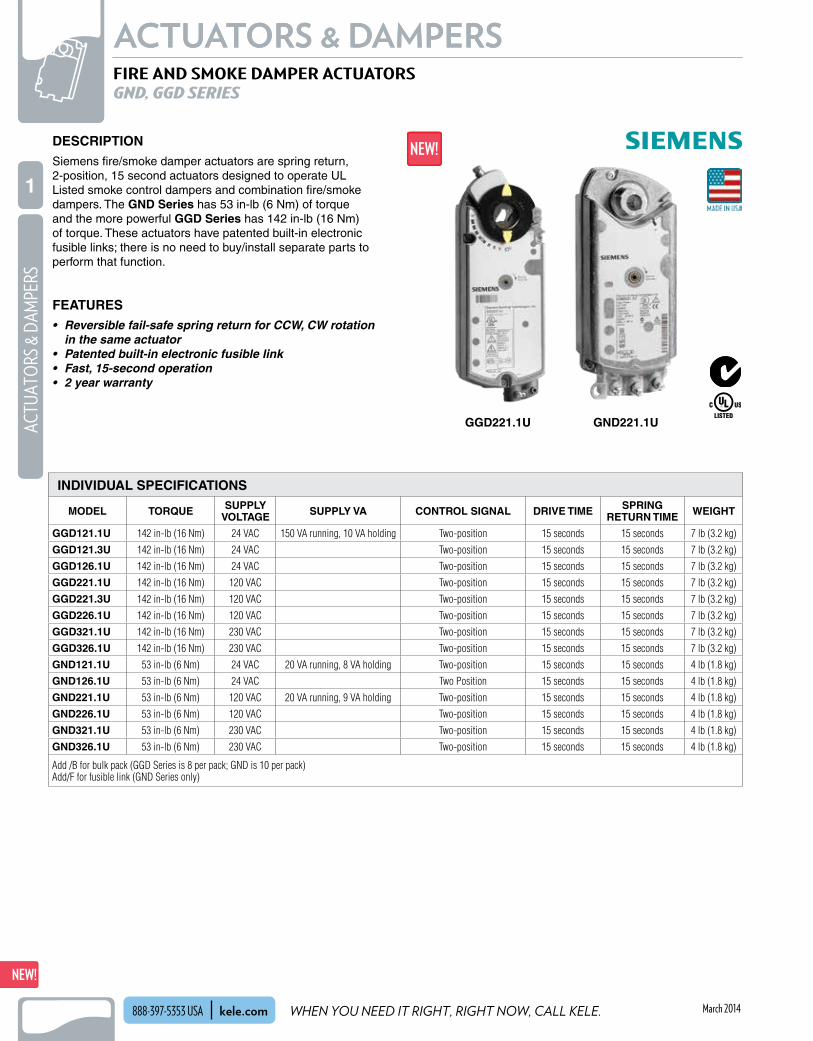
WHEN YOU NEED IT RIGHT, RIGHT NOW, CALL KELE.
NEW!ACTUATORS & DAMPERS
48
NEW!AC
TUAT
ORS
& D
AMPE
RS
1
kele.com888-397-5353 USA
NEW!ACTUATORS & DAMPERS
48
NEW!AC
TUAT
ORS
& D
AMPE
RS
1
March 2014
DESCRIPTIONSiemens fire/smoke damper actuators are spring return, 2-position, 15 second actuators designed to operate UL Listed smoke control dampers and combination fire/smoke dampers . The GND Series has 53 in-lb (6 Nm) of torque and the more powerful GGD Series has 142 in-lb (16 Nm) of torque . These actuators have patented built-in electronic fusible links; there is no need to buy/install separate parts to perform that function .
FEATURES• Reversible fail-safe spring return for CCW, CW rotation
in the same actuator• Patented built-in electronic fusible link• Fast, 15-second operation• 2 year warranty
FIRE AND SMOKE DAMPER ACTUATORSGND, GGD SERIES
GGD221.1U GND221.1U
INDIVIDUAL SPECIFICATIONS
MODEL TORQUE SUPPLY VOLTAGE SUPPLY VA CONTROL SIGNAL DRIVE TIME SPRING
RETURN TIME WEIGHT
GGD121.1U 142 in-lb (16 Nm) 24 VAC 150 VA running, 10 VA holding Two-position 15 seconds 15 seconds 7 lb (3.2 kg)
GGD121.3U 142 in-lb (16 Nm) 24 VAC Two-position 15 seconds 15 seconds 7 lb (3.2 kg)
GGD126.1U 142 in-lb (16 Nm) 24 VAC Two-position 15 seconds 15 seconds 7 lb (3.2 kg)
GGD221.1U 142 in-lb (16 Nm) 120 VAC Two-position 15 seconds 15 seconds 7 lb (3.2 kg)
GGD221.3U 142 in-lb (16 Nm) 120 VAC Two-position 15 seconds 15 seconds 7 lb (3.2 kg)
GGD226.1U 142 in-lb (16 Nm) 120 VAC Two-position 15 seconds 15 seconds 7 lb (3.2 kg)
GGD321.1U 142 in-lb (16 Nm) 230 VAC Two-position 15 seconds 15 seconds 7 lb (3.2 kg)
GGD326.1U 142 in-lb (16 Nm) 230 VAC Two-position 15 seconds 15 seconds 7 lb (3.2 kg)
GND121.1U 53 in-lb (6 Nm) 24 VAC 20 VA running, 8 VA holding Two-position 15 seconds 15 seconds 4 lb (1.8 kg)
GND126.1U 53 in-lb (6 Nm) 24 VAC Two Position 15 seconds 15 seconds 4 lb (1.8 kg)
GND221.1U 53 in-lb (6 Nm) 120 VAC 20 VA running, 9 VA holding Two-position 15 seconds 15 seconds 4 lb (1.8 kg)
GND226.1U 53 in-lb (6 Nm) 120 VAC Two-position 15 seconds 15 seconds 4 lb (1.8 kg)
GND321.1U 53 in-lb (6 Nm) 230 VAC Two-position 15 seconds 15 seconds 4 lb (1.8 kg)
GND326.1U 53 in-lb (6 Nm) 230 VAC Two-position 15 seconds 15 seconds 4 lb (1.8 kg)
Add /B for bulk pack (GGD Series is 8 per pack; GND is 10 per pack)Add/F for fusible link (GND Series only)

WE MAKE IT EASY.
NEW!
49
ACTUATORS & DAMPERSACTUATO
RS & DAMPERS
1
kele.com 888-397-5353 USA
NEW!
49
ACTUATORS & DAMPERSACTUATO
RS & DAMPERS
1
March 2014
FIRE AND SMOKE DAMPER ACTUATORSGND, GGD SERIES
Operating Voltage 24 VAC ±20%, 115 VAC ±15%Power Supply 230 VAC ±10% Frequency 50/60 Hz Power Consumption Running 150 VA Holding 10 VA Running Torque 142 lb-in (16 Nm) Spring Return Torque 108 lb-in (12 Nm) Minimum Stall Torque 350 lb-in (39 Nm) Torque Reduction at Elevated Temperature
Less than 10% Runtime for 90° Operating with Motor at 60 Hz
15 seconds nominal Closing (On Power Loss) with Spring Return
15 seconds maximum Life Expectancy Minimum 35,000 stroke cycles
Damper Shaft Size Standard 3/8" to 1" (8 to 25 .6 mm) Oversize 1 .05 inch maximum (26 .6 mm) Enclosure NEMA 1Housing Material Die cast aluminum alloyAmbient Temperature Operation 0° to 130°F (-18° to 55°C) One time 350°F (177°C) for 1/2 hour
(per UL555S) Storage and Transport
-25° to 158°F (-32° to 70°C) Agency Certification UL listed to UL873, cUL certified to
Canadian standard C22 .2 No . 24-93 Pre-Cabled Connection 18 AWG Dimensions See dimensions tableWeight ≈7 lbs . (3 .2 kg)
Eight pack ≈56 lbs . (25 .4 kg)
Operating Voltage 24 VAC/VDC ±20%, 230 VAC ±10%, 50/60 Hz
120 VAC ±10%, 60 Hz onlyPower Consumption 24 VAC/VDC Running 20 VA/12W Holding 8 VA/6W Power Consumption 120 VAC/230 VDC Running 20 VA Holding 9 VA Running Torque 53 lb-in (6 Nm) (minimum) Stall Torque (Minimum) 160 lb-in (18 Nm) Torque reduction at elevated temperature
Less than 10% Runtime for 90° 15 seconds nominal Closing (on power loss) with spring return
15 seconds maximum Nominal angle of rotation
95°Life Expectancy Minimum 35,000 full stroke cycles Damper Shaft Size 0 .5" (12 .7 mm) round Damper Shaft Length, Minimum
1 .4" (36 mm) Enclosure NEMA 1 Housing Material Die cast aluminum alloy
Ambient Conditions Operation 0° to 140°F (-18° to 60°C) one time
350°F (177°C) Storage and Transport
-40° to 158°F (-40° to 70°C) Humidity (Non-condensing)
Maximum 95% RH non-condensing Teflon® Cable 400°F (200°C) Fixed Dual End Switches AC Rating 24 VAC to 250 VAC, 24 VDC 6A
resistive/ 2 FLA/12 LRA Temperature Rating 350°F (177°C) Agency Certification UL873 , cUL C22 .2 No . 24-93 , AS/
NZS 2064 1/2:1997; conforms to CE requirements for the EMC and low voltage directives; Australian Electromagnetic Compatibility (EMC) per AS/NZS 4251 .1/2:1999 (C-tick)
Pre-Cabled Connection Type FEP Teflon® jacketed Length 3 ft (0 .9m), 19/30 strand 18 GA Country of Origin USA Dimensions See dimensions table Weight ≈4 lb (1 .8 kg) Ten pack ≈40 lb (18 kg)
GGD SPECIFICATIONS
GND SPECIFICATIONS

WHEN YOU NEED IT RIGHT, RIGHT NOW, CALL KELE.
NEW!ACTUATORS & DAMPERS
50
NEW!AC
TUAT
ORS
& D
AMPE
RS
1
kele.com888-397-5353 USA
NEW!ACTUATORS & DAMPERS
50
NEW!AC
TUAT
ORS
& D
AMPE
RS
1
March 2014
FIRE AND SMOKE DAMPER ACTUATORSGND, GGD SERIES
DIMENSIONS
MODEL TORQUE DIMENSIONS MAXIMUM SHAFT DIAMETER
MINIMUM SHAFT LENGTH
ENCLOSURE RATING
WEIGHT
GGD121.1U 142 in-lb (16 Nm) 3.25"H x 3.9"W x 11"L (8.26 x 9.9 x 27.9 cm)
1" (2.54 cm) 3/4" (1.9 cm) Nema 1 4.8 (2.2 kg)
GGD121.3U 142 in-lb (16 Nm) 3.25"H x 3.9"W x 11"L (8.26 x 9.9 x 27.9 cm)
1.05" (26.6mm) 3/4" (1.9 cm) Nema 1 4.8 (2.2 kg)t
GGD126.1U 142 in-lb (16 Nm) 3.25"H x 3.9"W x 11"L (8.26 x 9.9 x 27.9 cm)
1" (2.54 cm) 3/4" (1.9 cm) Nema 1 4.8 (2.2 kg)
GGD221.1U 142 in-lb (16 Nm) 3.25"H x 3.9"W x 11"L (8.26 x 9.9 x 27.9 cm)
1" (2.54 cm) 3/4" (1.9 cm) Nema 1 4.8 (2.2 kg)
GGD221.3U 142 in-lb (16 Nm) 3.25"H x 3.9"W x 11"L (8.26 x 9.9 x 27.9 cm)
1.05" (26.6mm) 3/4" (1.9 cm) Nema 1 4.8 (2.2 kg)
GGD226.1U 142 in-lb (16 Nm) 3.25"H x 3.9"W x 11"L (8.26 x 9.9 x 27.9 cm)
1" (2.54 cm) 3/4" (1.9 cm) Nema 1 4.8 (2.2 kg)
GGD321.1U 142 in-lb (16 Nm) 3.25"H x 3.9"W x 11"L (8.26 x 9.9 x 27.9 cm)
1" (2.54 cm) 3/4" (1.9 cm) Nema 1 4.8 (2.2 kg)
GGD326.1U 142 in-lb (16 Nm) 3.25"H x 3.9"W x 11"L (8.26 x 9.9 x 27.9 cm)
1" (2.54 cm) 3/4" (1.9 cm) Nema 1 4.8 (2.2 kg)
GND121.1U 53 in-lb (6 Nm) 3.25"H x 3.9"W x 11"L (8.26 x 9.9 x 27.9 cm)
1" (2.54 cm) 3/4" (1.9 cm) Nema 1 2.9 (1.3 kg)
GND126.1U 53 in-lb (6 Nm) 3.25"H x 3.9"W x 11"L (8.26 x 9.9 x 27.9 cm)
1" (2.54 cm) 3/4" (1.9 cm) Nema 1 2.9 (1.3 kg)
GND221.1U 53 in-lb (6 Nm) 3.25"H x 3.9"W x 11"L (8.26 x 9.9 x 27.9 cm)
1" (2.54 cm) 3/4" (1.9 cm) Nema 1 2.9 (1.3 kg)
GND226.1U 53 in-lb (6 Nm) 3.25"H x 3.9"W x 11"L (8.26 x 9.9 x 27.9 cm)
1" (2.54 cm) 3/4" (1.9 cm) Nema 1 2.9 (1.3 kg)
GND321.1U 53 in-lb (6 Nm) 3.25"H x 3.9"W x 11"L (8.26 x 9.9 x 27.9 cm)
1" (2.54 cm) 3/4" (1.9 cm) Nema 1 2.9 (1.3 kg)
GND326.1U 53 in-lb (6 Nm) 3.25"H x 3.9"W x 11"L (8.26 x 9.9 x 27.9 cm)
1" (2.54 cm) 3/4" (1.9 cm) Nema 1 2.9 (1.3 kg)
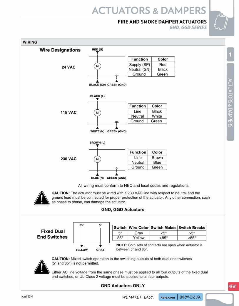
WE MAKE IT EASY.
NEW!
51
ACTUATORS & DAMPERSACTUATO
RS & DAMPERS
1
kele.com 888-397-5353 USA
NEW!
51
ACTUATORS & DAMPERSACTUATO
RS & DAMPERS
1
March 2014
FIRE AND SMOKE DAMPER ACTUATORSGND, GGD SERIES
All wiring must conform to NEC and local codes and regulations.
Wire Designations
24 VAC
115 VAC
230 VAC
BLUE (N) GREEN (GND)
Function ColorLine Brown
Neutral BlueGround Green
M
BROWN (L)
Switch Switch Makes Switch BreaksWire ColorFixed Dual
End Switches 5° Gray <5°85° Yellow >85°
>5°<85°
YELLOW
85°
GRAY
5°
M
WHITE (N)
BLACK (L)
GREEN (GND)
Function ColorLine Black
Neutral WhiteGround Green
M
BLACK (G0)
RED (G)
GREEN (GND)
FunctionSupply (SP)Neutral (SN)
Ground
ColorRed
BlackGreen
CAUTION: The actuator must be wired with a 230 VAC line with respect to neutral and the ground lead must be connected for proper protection of the actuator. Any other connection, such as phase to phase, can damage the actuator.
CAUTION: Mixed switch operation to the switching outputs of both dual end switches
(5° and 85°) is not permitted.
Either AC line voltage from the same phase must be applied to all four outputs of the fixed dual
end switches, or UL-Class 2 voltage must be applied to all four outputs.
NOTE: Both sets of contacts are open when actuator is between 5° and 85°.
GND, GGD Actuators
GND Actuators ONLY
WIRING

WHEN YOU NEED IT RIGHT, RIGHT NOW, CALL KELE.
NEW!ACTUATORS & DAMPERS
52
NEW!AC
TUAT
ORS
& D
AMPE
RS
1
kele.com888-397-5353 USA
NEW!ACTUATORS & DAMPERS
52
NEW!AC
TUAT
ORS
& D
AMPE
RS
1
March 2014
ORDERING INFORMATION
FIRE AND SMOKE DAMPER ACTUATORSGND, GGD SERIES
MODEL DESCRIPTIONGGD121.1U F/S, 142 in-lb, 2-position, 24 VAC, 15-second returnGGD121.3U F/S, 142 in-lb, 2-position, 24 VAC, 15-second return, oversize shaft adapterGGD126.1U F/S, 142 in-lb, 2-position, 24 VAC, 15-second return, auxiliary switchesGGD221.1U F/S, 142 in-lb, 2-position, 120 VAC, 15-second returnGGD221.3U F/S, 142 in-lb, 2-position, 120 VAC, 15-second return, oversize shaft adapterGGD226.1U F/S, 142 in-lb, 2-position, 120 VAC, 15-second return, auxiliary switchesGGD321.1U F/S, 142 in-lb, 2-position, 230 VAC, 15-second returnGGD326.1U F/S, 142 in-lb, 2-position, 230 VAC, 15-second return, auxiliary switchesGND121.1U F/S, 53 in-lb, 2-position, 24 VAC, 15-second returnGND126.1U F/S, 53 in-lb, 2-position, 24 VAC, 15-second return, auxiliary switchesGND221.1U F/S, 53 in-lb, 2-position, 120 VAC, 15-second returnGND226.1U F/S, 53 in-lb, 2-position, 120 VAC, 15-second return, auxiliary switchesGND321.1U F/S, 53 in-lb, 2-position, 230 VAC, 15-second return, auxiliary switchesGND326.1U F/S, 53 in-lb, 2-position, 230 VAC, 15-second return, auxiliary switches
NOTES: Add /B for bulk pack (GGD Series is 8 per pack; GND is 10 per pack) Add/F for fusible link (GND Series only)
Standard shaft adapter is 3/8 to 1 in (8 to 25 .6mm) Oversize shaft adapter is 1 .05 in maximum (26 .6mm) - (GGD series only)
ACCESSORIES GND SERIES ASK79.165 Electronic fusible link 165°F, 74°CASK79.212 Electronic fusible link 212°F, 100°CASK79.250 Electronic fusible link 250°F, 121°CASK79.350 Electronic fusible link 350°F, 177°C
GGD SERIES 985-006 Anti-rotation bracket985-004 Self centering adapaterASK74.1 Oversized shaft adapter up to 1.05 in (26.6mm)985-035P25 Conduit adapter male (box of 25 only)985-008P20 Conduit adapter female 1/2 in (12mm) (box of 20 only)

WE MAKE IT EASY.
NEW!
53
ACTUATORS & DAMPERSACTUATO
RS & DAMPERS
1
kele.com 888-397-5353 USAMarch 2014
Control Signal Two-positionMotor DC with brushesWiring MS4xxx 32" leads, 18 AWG and 7/8"
knockout holes for conduit fittings MS8xxx 39" leads, 18 AWG and 7/8"
knockout holes for conduit fittings
Action CW/CCW mounting method
Rotation 95° ±3°, mechanically limitedNoise Driving Open 80 dBA @ 3' (1 .0 m) Holding 20 dBA @ 3' (1 .0 m) no audible noiseLife Expectancy 30,000 cyclesOperating Temperature 0° to 130°F (-18° to 55°C)Operating Humidity 5 to 95% RH, non-condensingApprovals CE, C-TICK, cULus,UL873, NEMA1Warranty 5 years
FIRE AND SMOKE DAMPER ACTUATORSMS4XXX, MS81XX SERIES
DESCRIPTION
Honeywell fire and smoke damper actuators are designed to meet both UL-555 and UL-555S 350°F safety requirements for combined fire and smoke applications . The fast-acting actuators close dampers in 15-20 seconds, and the integral spring return ensures the consistent, proper level of torque .
FEATURES
• Designed to meet UL-555 and UL-555S requirements• Robust die-cast aluminum housing for protection and
long service life• Maximum spring return timing of 15-20 seconds• Reliably built by the industry leader• Energy-saving patented design• No audible noise during holding
APPLICATIONFire and Smoke actuator replacement must be installed correctly, per local codes, and approved by the Local Authority Having Jurisdiction (AHJ) . Honeywell recommends following all local, state and national codes for periodic testing of the entire smoke control system . Refer to National
COMMON SPECIFICATIONS
MS4120F1006
Fire Protection Association (NFPA) National Fire Codes NFPA90A, NFPA92A, and NFPA92B for the application . NFPA recommends periodic examination of each fire/smoke damper (annually or semi-annually) to ensure proper performance .
MS4104F1210
Model Torque Dimensions Maximum Shaft Diameter
Minimum Shaft Length
Weight Enclosure Rating
MS4xxx 30 in-lb (3.4 Nm) 8.94"H x 5.125"W x 3.25"D (22.7 x 13.0 x 8.3 cm)
0.5” (1.3 cm) 2" (5.1 cm) 5.0 lb (2.3 kg) NEMA 1 (IP40)MS8xxx 80 in-lb (9 Nm)
MSxx20 175 in-lb (20 Nm)10.7"H x 2.9"W x 3.9"D (2.71 x 7.5 x 10.0 cm)
1.03” (2.6 cm) 1.0” (2.5 cm) 7.0 lb (3.2 kg) NEMA 2 (IP54)
DIMENSIONS

WHEN YOU NEED IT RIGHT, RIGHT NOW, CALL KELE.
NEW!ACTUATORS & DAMPERS
54
NEW!AC
TUAT
ORS
& D
AMPE
RS
1
kele.com888-397-5353 USA March 2014
FIRE AND SMOKE DAMPER ACTUATORSMS4XXX, MS81XX SERIES
ORDERING INFORMATION
MODEL DESCRIPTIONMS4104F1010 Fire/smoke actuator, 30 in-lb, 120 VACMS4104F1210 Fire/smoke actuator, 30 in-lb, 120 VAC, w/ 2 aux. switchesMS4604F1010 Fire/smoke actuator, 30 in-lb, 230 VACMS4604F1210 Fire/smoke actuator, 30 in-lb, 230 VAC, w/ 2 aux. switchesMS8104F1010 Fire/smoke actuator, 30 in-lb, 24 VACMS8104F1210 Fire/smoke actuator, 30 in-lb, 24 VAC, w/ 2 aux. switchesMS4109F1010 Fire/smoke actuator, 80 in-lb, 120 VACMS4109F1210 Fire/smoke actuator, 80 in-lb, 120 VAC, w/ 2 aux. switchesMS4609F1010 Fire/smoke actuator, 80 in-lb, 230 VACMS4609F1210 Fire/smoke actuator, 80 in-lb, 230 VAC, w/ 2 aux. switchesMS8109F1010 Fire/smoke actuator, 80 in-lb, 24 VACMS8109F1210 Fire/smoke actuator, 80 in-lb, 24 VAC, w/ 2 aux. switchesMS8120F1002 Fire/smoke actuator, 175 in-lb, 24 VACMS8120F1200 Fire/smoke actuator, 175 in-lb, 24 VAC, w/ 2 aux. switchesMS4120F1006 Fire/smoke actuator, 175 in-lb, 120 VACMS4120F1204 Fire/smoke actuator, 175 in-lb, 120 VAC, w/ 2 aux. switches
ACCESSORIES 201391 Shaft adapter for 3/8" shafts 205649 Surface mounting bracket (not supplied with actuator) for MLxx15, MSxx09 32003532-005 Auxiliary switch, dual SPDT, for MLxx15, MSxx09 fire/smoke actuators
INDIVIDUAL SPECIFICATIONS
Model Torque Supply Voltage Supply Current Auxiliary SwitchDrive Time
Spring Return Time
MS8104F1010
30 in-lb (3.4 Nm)
24 VAC +20%, -10%, 50/60 Hz 16 VA running, 8 VA holdingNone
15 seconds 15 seconds
MS8104F1210 2 SPST, 5A res., 3A ind. @ 250 VAC
MS4104F1010120 VAC +10%, 60 Hz 0.18A running, 0.11A holding
None
MS4104F1210 2 SPST, 5A res., 3A ind. @ 250 VAC
MS4604F1010230 VAC ±10%, 50/60 Hz 0.13A running, 0.10A holding
None
MS4604F1210 2 SPST, 5A res., 3A ind. @ 250 VAC
MS8109F1010
80 in-lb (9 Nm)
24 VAC +20%, -10%, 50/60 Hz 23VA running, 8VA holdingNone
MS8109F1210 2 SPST, 5A res., 3A ind. @ 250 VAC
MS4109F1010120 VAC ±10%, 50/60Hz 0.25A running, 0.13A holding
None
MS4109F1210 2 SPST, 5A res., 3A ind. @ 250 VAC
MS4609F1010230 VAC ±10%, 50/60Hz 0.13A running, 0.09A holding
None
MS4609F1210 2 SPST, 5A res., 3A ind. @ 250 VAC
MS8109F1010
175 in-lb (20 Nm)
24 VAC +20%, -10%, 50/60 Hz None
MS8109F1210 2 SPST, 5A res., 3A ind. @ 250 VAC
MS8120F1002120 VAC +10%, 60 Hz 0.35A running, 0.15A holding
None
MS8120F1200 2 SPST, 5A res., 3A ind. @ 250 VAC
MS4120F1006230 VAC +10%, 50/60 Hz 0.20A running, 0.14A holding
None
MS4120F1204 2 SPST, 5A res., 3A ind. @ 250 VAC

WE MAKE IT EASY.
NEW!
55
ACTUATORS & DAMPERSACTUATO
RS & DAMPERS
1
kele.com 888-397-5353 USAMarch 2014
Motor Brushless DCWiring 3-foot leads, 18 AWG, 1/2" NPT
conduit connectionFeedback 2-10 VDC (FSAF24-SR only)Action CW/CCW mounting methodRotation 95°Manual Override 3 mm hex crank (FSAF only)Noise 40 db drive, 62 db springLife Expectancy 20,000 cycles per UL555S
Operating Temperature FSLF, FSNF 32° to 122°F (0° to 50°C) normal
duty; 3 on/off cycles after 30 minutes at ambient temperature of 350°F (177°C) safety duty;
FSAF -22° to 122°F (-30° to 50°C) normal duty; 3 on/off cycles after 30 minutes at ambient temperature of 250°F (121°C) safety duty
Operating Humidity 5 to 95% RHApprovals cULusWarranty 5 years
FIRE AND SMOKE DAMPER ACTUATORSFSLF, FSNF, FSAF SERIES
DESCRIPTIONBelimo’s broad product line of fire and smoke damper actuators covers the established range of system applications including active smoke control for stairwell, under-floor and other pressurization applications .
FEATURES
• ISO 9001 Certified Quality Control and a 5-year warranty assure reliable operation
• 24, 120 and 230 VAC availibility to meet various installation requirements
• 24 VDC model (FSAF only) with 2-position and proportional control for DC power applications
• Unique FSAF24-BAL actuator allows duct balancing capabilities in fire and smoke dampers
• UL555 and UL555S listed with U.S. damper manufacturers
COMMON SPECIFICATIONS
ORDERING INFORMATION AND INDIVIDUAL SPECIFICATIONS
Note: Add “-S” suffix to model number for models with auxiliary contacts: 2 SPST, 3A (0.5 A inductive) @ 125/250 VACNote: FSAFB24-SR model available with shorter 8" connection cable. Add “-SC” to the end of the model number.
FSAF24
FSLF120
Model Torque Supply Voltage Supply VA Control Signal Drive TimeSpring Return
TimeWeight
FSLF24 30 in-lb (3.5 Nm) 24 VAC 5 VA Two-position 15 seconds 15 seconds 3.4 lb (1.5 kg)
FSLF120 30 in-lb (3.5 Nm) 120 VAC 18 VA Two-position 15 seconds 15 seconds 4.0 lb (1.8 kg)
FSLF230 30 in-lb (3.5 Nm) 230 VAC 17 VA Two-position 15 seconds 15 seconds 4.0 lb (1.8 kg)
FSNF24 70 in-lb (7.8 Nm) 24 VAC 27 VA Two-position 15 seconds 15 seconds 6.0 lb (2.7 kg)
FSNF120 70 in-lb (7.8 Nm) 120 VAC 27 VA Two-position 15 seconds 15 seconds 6.1 lb (2.8 kg)
FSNF230 70 in-lb (7.8 Nm) 230 VAC 27 VA Two-position 15 seconds 15 seconds 6.1 lb (2.8 kg)
FSAF24 133 in-lb (15 Nm) 24 VAC/VDC 10 VA Two-position 75 seconds 20 seconds 5.7 lb (2.6 kg)
FSAF120 133 in-lb (15 Nm) 120 VAC 11 VA Two-position 75 seconds 20 seconds 6.1 lb (2.8 kg)
FSAF230 133 in-lb (15 Nm) 230 VAC 11 VA Two-position 75 seconds 20 seconds 6.1 lb (2.8 kg)
FSAF24-SR 133 in-lb (15 Nm) 24 VAC/VDC 11 VAProportional 2-10 VDC,
4-20 mA75 seconds 20 seconds 5.7 lb (2.6 kg)
FSAF24-BAL 133 in-lb (15 Nm) 24 VAC/VDC 10 VAFloating/3-position, built-
in potentiometer75 seconds 20 seconds 5.7 lb (2.6 kg)
FSAFB24-SR 180 in-lb (20Nm) 24 VAC 9 VAProportional, 2-10 VDC,
4-20 mA75 seconds 20 seconds 4.6 lb (2.1 kg)

WHEN YOU NEED IT RIGHT, RIGHT NOW, CALL KELE.
NEW!ACTUATORS & DAMPERS
56
NEW!AC
TUAT
ORS
& D
AMPE
RS
1
kele.com888-397-5353 USA March 2014
FSAFxx-SFSAF24R-SR-S FSNFxx-S
10°
10°
85°
5°
85°30° to90°
FSLFxx-S
NOTE: Refer to Belimo FS Actuators Guide for complete wiring information.
Line Voltage
FSAF24-SR, Proportional FSLF, FSNF, FSAF, 2-position
6
FSxF120,FSxF230
FSxF24
Provide overload protection and disconnect as required.
Actuator may also be powered by 24 VDC.
No ground connection required for AF models.Double insulated.
Only connect common to neg. (–) leg of control circuits.
6 The ZG-R01-500 Ω resistor converts a 4 to 20 mAcontrol signal to 2 to 10 VDC.
AF models meet cULus or UL and CSA Standardrequirments without the need of an electrical groundconnection. LF and NF high voltage models requireground.
CAUTION Equipment Damage!Actuators may be connected in parallel.Power consumption and input impedance must beobserved.
NOTE: Refer to Belimo FS Actuators Guide for complete wiring information.
WIRING
FIRE AND SMOKE DAMPER ACTUATORSFSLF, FSNF, FSAF SERIES
Thermal sensor application
Smoke detector or relay from areasmoke detection system
To alarmsystem
HOT120 or24 VAC
N orCOM
165°F
BELIMOFSxxACTUATOR
F & S Damper
Fusible link and shaft spring application
Smoke detector or relay from areasmoke detection system
To alarmsystem
HOT120 or24 VAC
N orCOM
BELIMOFSxxACTUATOR
F & S Damper
AUXILIARY SWITCH WIRING
IMPORTANT: In most jurisdictions, replacement is considered a normal repair and no permit is required . A record must be kept on site per NFPA 105 . UL expects instructions to be used . See www .belimo .com/firesmoke . Confirm with Local Authority Having Jurisdiction (AHJ) .
APPLICATION WIRING

WE MAKE IT EASY.
NEW!
57
ACTUATORS & DAMPERSACTUATO
RS & DAMPERS
1
kele.com 888-397-5353 USAMarch 2014
ZONECONTROLLER
ZONE 1 ZONE 2 ZONE 3
RETURN AIR
SUPPLY AIR
FROM ADDITIONAL ZONES
TO ADDITIONAL ZONES
Size 6" round through 16" round (even sizes)
Type Round, single-blade, 90° rotationShaft 1/2" (1 .3 cm) diameter shaft, 3 .9"
(9 .9 cm) lengthActuator Bracket Pre-drilled holes to fit Honeywell or
Kele 35 in-lb or 44 in-lb actuatorsOperating Torque Less than 35 in-lb (4 Nm)Maximum Static Pressure
4" WC (1 .0 kPa)Maximum Velocity 2500 ft/min (17 .8 m/s)Leakage Class 12 .5 cfm per sq . ft . @ 1" WC 17 .6 cfm per sq . ft . @ 2" WC 21 .6 cfm per sq . ft . @ 3" WC 25 .0 cfm per sq . ft . @ 4" WCFrame 6" through 10" Mill galvanized, 24 gauge, sleeve-
type, spiral duct, crimped on downstream side
12" through 16" Mill galvanized, 22 gauge, sleeve-type, spiral duct, crimped on downstream side
Bearings Flanged bronze oilite, pressed onto frame
Blade Design 16 gauge galvanized steel blade with closed-cell neoprene seal
Operating Temperature 32° to 130°F (0° to 54°C)Warranty 1 year
ROUND DAMPERSD690 SERIES
DESCRIPTIONThe D690 Series round control dampers are low-leakage, single blade dampers designed for use in conventional air handling system round ductwork . They come standard with an actuator mounting bracket that accommodates the Honeywell ML6161/ML7161/MN6105/MN7505 and the Kele KA-35/KA-44 direct-coupled actuators . The dampers are available for standard same-day shipping from Kele with or without an actuator pre-mounted .
FEATURES• Neoprene seal for tight closing and low leakage• Oilite bearings for long life• Optional Honeywell or Kele actuator pre-mounted
APPLICATIONThe D690 Series is intended to be used in commercial zoning systems as an individual zone damper controlled by a zone thermostat, or as a bypass damper controlled by a duct static pressure sensor/controller .
SPECIFICATIONS
Model Pressure drop "WC (kPa)
Flow rate CFM
D690A1002
0.05 (0.012) 180
0.075 (0.019) 210
0.10 (0.025) 240
D690A1010
0.05 (0.012) 410
0.075 (0.019) 485
0.10 (0.025) 580
D690A1028
0.05 (0.012) 693
0.075 (0.019) 849
0.10 (0.025) 980
D690A1036
0.05 (0.012) 1200
0.075 (0.019) 1460
0.10 (0.025) 1600
D690A1044
0.05 (0.012) 1336
0.075 (0.019) 1636
0.10 (0.025) 1890
D690A1051
0.05 (0.012) 1690
0.075 (0.019) 2080
0.10 (0.025) 2400
PRESSURE DROP AND FLOW RATE
D690A1044
D690A1044/KA-35-VAV
ZONE DAMPER APPLICATION

WHEN YOU NEED IT RIGHT, RIGHT NOW, CALL KELE.
NEW!ACTUATORS & DAMPERS
58
NEW!AC
TUAT
ORS
& D
AMPE
RS
1
kele.com888-397-5353 USA March 2014
DIMENSIONS
ROUND DAMPERSD690 SERIES
ORDERING INFORMATION
Note: Add the following weights when ordering with actuator: KA-35-P or ML7161A2008 1.3 lb (.59 kg) KA-35-VAV or ML6161A2009 1.1 lb (.50 kg)
RELATED PRODUCTS PAGE201052A Auxiliary switch (1 SPDT) for ML6161/ML7161/KA-35 actuators TT-470 Tilt transducer with 1/2-in crank arm, 4-20 mA loop powered 6
Model Dimensions Weight
D690A1002 6” diameter, 12” length 3.0 lb (1.36 kg)
D690A1010 8” diameter, 12” length 4.0 lb (1.81 kg)
D690A1028 10” diameter, 12” length 5.0 lb (2.27 kg)
D690A1036 12” diameter, 13” length 6.0 lb (2.72 kg)
D690A1044 14” diameter, 15” length 8.0 lb (3.63 kg)
D690A1051 16” diameter, 17” length 10.0 lb (4.54 kg)
MODEL DESCRIPTIOND690A1002 6" round damper with actuator mounting plate, 12" spiral duct lengthD690A1010 8" round damper with actuator mounting plate, 12" spiral duct lengthD690A1028 10" round damper with actuator mounting plate, 12" spiral duct lengthD690A1036 12" round damper with actuator mounting plate, 13" spiral duct lengthD690A1044 14" round damper with actuator mounting plate, 15" spiral duct lengthD690A1051 16" round damper with actuator mounting plate, 17" spiral duct lengthD690A1002/KA-35-P 6" D690A1002 with Kele non-spring return proportional actuatorD690A1010/KA-35-P 8" D690A1010 with Kele non-spring return proportional actuatorD690A1028/KA-35-P 10" D690A1028 with Kele non-spring return proportional actuatorD690A1036/KA-35-P 12" D690A1036 with Kele non-spring return proportional actuatorD690A1044/KA-35-P 14" D690A1044 with Kele non-spring return proportional actuatorD690A1051/KA-35-P 16" D690A1051 with Kele non-spring return proportional actuatorD690A1002/KA-35-VAV 6" D690A1002 with Kele non-spring return floating actuatorD690A1010/KA-35-VAV 8" D690A1010 with Kele non-spring return floating actuatorD690A1028/KA-35-VAV 10" D690A1028 with Kele non-spring return floating actuatorD690A1036/KA-35-VAV 12" D690A1036 with Kele non-spring return floating actuatorD690A1044/KA-35-VAV 14" D690A1044 with Kele non-spring return floating actuatorD690A1051/KA-35-VAV 16" D690A1051 with Kele non-spring return floating actuatorD690A1002/ML7161A2008 6" D690A1002 with Honeywell non-spring return proportional actuatorD690A1010/ML7161A2008 8" D690A1010 with Honeywell non-spring return proportional actuatorD690A1028/ML7161A2008 10" D690A1028 with Honeywell non-spring return proportional actuatorD690A1036/ML7161A2008 12" D690A1036 with Honeywell non-spring return proportional actuatorD690A1044/ML7161A2008 14" D690A1044 with Honeywell non-spring return proportional actuatorD690A1051/ML7161A2008 16" D690A1051 with Honeywell non-spring return proportional actuatorD690A1002/ML6161A2009 6" D690A1002 with Honeywell non-spring return floating actuatorD690A1010/ML6161A2009 8" D690A1010 with Honeywell non-spring return floating actuatorD690A1028/ML6161A2009 10" D690A1028 with Honeywell non-spring return floating actuatorD690A1036/ML6161A2009 12" D690A1036 with Honeywell non-spring return floating actuatorD690A1044/ML6161A2009 14" D690A1044 with Honeywell non-spring return floating actuatorD690A1051/ML6161A2009 16" D690A1051 with Honeywell non-spring return floating actuator

WE MAKE IT EASY.
NEW!
59
ACTUATORS & DAMPERSACTUATO
RS & DAMPERS
1
kele.com 888-397-5353 USAMarch 2014
Size 4", 5", 6", 7", 8", 9", 10" to 24" (even)Type Round, single-blade, 90° rotationShaft 1/2" (1 .3 cm) diameter shaft, 7" (17 .8
cm) lengthActuator Bracket Optional, galvanized or stainless
steel, 5 .5"W x 9 .3"L (to shaft center)Operating Torque (4xD") + 20 in-lb (with seals);
(1 .5xD") + 20 in-lb (without seals)Maximum Static Pressure
10" WC (4" to 6") 8" WC (7" to 12") 6" WC (>12")Maximum Velocity 4000 ft/min (28 .5 m/s)Leakage Class AMCA Class 1 (with seals); 1 .4%
to 5 .5% of maximum flow (without seals)
Frame Galvanized 20-gauge steelBearings Stainless steelBlade Design Riveted double-layer galvanized
steel, full blade neoprene seals (standard, others optional)
Operating Temperature -50° to 250°F (-46° to 121°C)Dimensions 4" through 24" diameter, 7" frame
lengthWeight Approximately 1 lb per inch diameterRoHS Statement YesWarranty 1 year
ROUND CONTROL DAMPERSCDRS25 SERIES
DESCRIPTIONCDRS25 Series round damper frames are made of 20-gauge welded, galvanized steel, 7" in length . Blades are double-skin galvanized steel, strength-equivalent to 14-gauge steel but lighter to handle . Shaft extensions are half-inch diameter with stainless steel bearings for long life damper actuation . Standard neoprene blade edge seals offer superior low-leakage performance . Optional aluminum or stainless steel construction is available, as well as an actuator mounting bracket .
FEATURES
• Round sizes from 4" to 24" • Velocities up to 4000 FPM • Neoprene blade seal standard • 20-gauge frame • Two-ply blade, strength equivalent to 14-gauge steel
OPERATION
The CDRS25 is ideal for exhaust air modulation, supply air volume control, zone temperature control, minimum outdoor air intake control, and many other applications in both high-velocity and high-pressure systems . Made specifically for easy installation in spiral ductwork, stiffener beads allow for easy sealing of duct connections .
OPTIONS• Edge seals (none, silicon, EPDM, Viton®)• Stainless steel construction• Aluminum construction• Actuator mounting bracket
SPECIFICATIONS

WHEN YOU NEED IT RIGHT, RIGHT NOW, CALL KELE.
NEW!ACTUATORS & DAMPERS
60
NEW!AC
TUAT
ORS
& D
AMPE
RS
1
kele.com888-397-5353 USA March 2014
Pressure/Class Required Rating Extended Ranges (Opt.)
Leakage, FT3/MIN/FT2 (L/S/M2)
4" (1.0 kPa)1" (0.25 kPa) 8" (2.0 kPa) 12" (3.0 kPa)
8 (40.6)3 (15.2)1A 11 (55.9) 14 (71.1)
8 (40.6)4 (20.3) 11 (55.9) 14 (71.1)
20 (102)10 (50.8) 28 (142) 35 (178)
80 (406)40 (203)
1
2
3 112 (569) 140 (711)
7”(17.8)
in(cm)
D - Diameter
Sheet metal screw(outside bead)
DamperStiffener bead
Spiral DuctSpiral Duct
INSTALLATION
ROUND CONTROL DAMPERSCDRS25 SERIES
ORDERING INFORMATION
Example: CDRS25N1B(12) CDRS25 round steel control damper, with seals and actuator mounting plate, 12" diameter.* 316 stainless steel also available as special order, call Kele
MODEL DESCRIPTIONCDRS25G Round galvanized steel control damperCDRS25A Round aluminum control damperCDRS25S Round 304* stainless steel control damper BLADE SEAL OPTIONS N Standard neoprene seals, AMCA Class 1 leakage X No blade seals, no leakage class, approximate leakage 1.4% to 5.5% of maximum flow at 4" W.C., not recommended for OSA intake E EPDM blade seals, AMCA Class 1 leakage S Silicone blade seals, 400°F (204°C), AMCA Class 1 leakage V Viton blade seals, AMCA Class 1 leakage AXLE CONSTRUCTION 1 Standard galvanized steel axle, 1/2" diameter, extending 5.5" outside damper 2 Stainless steel axle, 1/2" diameter, extending 5.5" outside damper (Note: used on all stainless steel dampers) MOTOR MOUNTING OPTIONS X No mounting bracket, with 5.5" shaft extension B Galvanized steel actuator mounting plate, 16 AWG, 5.5"W x 12"L, with 4" shaft extension SSB Stainless steel actuator mounting plate, 16 AWG, 5.5"W x 12"L, with 4" shaft extension SIZE (OUTSIDE DIAMETER IN INCHES) (OD) Duct outside diameter (4, 5, 6, 7, 8, 9, 10, 12, 14, 16, 18, 20, 22, 24) inches available Note: All units are furnished approximately 1/8" smaller than the outside diameter dimension to facilitate spiral duct connection.
PERFORMANCE REFERENCE STANDARD PER AMCA
ACCESSORIES PAGETS-470 Damper position switch with SPDT switch, for 1/2" shaft 4TS-470-2 Damper position switch with two SPDT switches, for 1/2" shaft 4TS-470-P Damper position switch with SPDT switch, for 1/2" shaft,
stainless steel housing, and plenum-rated cable 4TS-475 Non-mercury damper position switch, SPDT, for 1/2" damper shaft 5TT-470 Tilt transducer with 1/2-in crank arm, 4-20 mA loop powered 6

WE MAKE IT EASY.
NEW!
61
ACTUATORS & DAMPERSACTUATO
RS & DAMPERS
1
kele.com 888-397-5353 USAMarch 2014
Type Parallel or opposed bladeShaft 6"L x 0 .5" Dia . (15 .2 x 1 .3 cm)
located on linkage sideFrame Equivalent 13 gauge galvanized
(CD 50 aluminum); 5" face-to-face dimension
Bearings SyntheticBlade Design 6" galvanized steel for CD40, CD60;
6" aluminum for CD50; blade pins 0 .5" steel hex
Side Seals Self-adjusting steel (CD45, 46, 50, 60)Linkage Concealed in frameAvailable Options Flanges (front and/or rear)Weight 7 lbs/sq . ft (shipping weight estimate)RoHS Statement YesWarranty 1 year
RECTANGULAR DAMPERSCD40, CD50, CD60 SERIES
DESCRIPTIONRuskin parallel and opposed-blade HVAC control dampers are custom made-to-order . The damper frames are made of galvanized steel in a channel frame construction, offering an equivalent 13-gauge metal strength . The CD40 Series has 6" wide V-groove blades that are made of 16-gauge galvanized steel with synthetic bearings . The CD50 has aluminum airfoil blades with synthetic bearings . CD60 dampers offer 14-gauge blades .
CD44 Basic control damper, approximately 4% leakageCD45 Standard control damper, AMCA Class 3CD46 Low leakage control damper, AMCA Class 2CD50 Aluminum frame air foil, ultra-low AMCA Class 1ACD60 Steel air foil, ultra-low AMCA Class 1A
INDIVIDUAL SPECIFICATIONS
CD-46
COMMON SPECIFICATIONS
CD44 CD45 CD46 CD50 CD60
Blades 16-gauge V-groove 16-gauge V-groove 16-gauge V-groove Aluminum airfoil 14-gauge steel airfoil
Jamb seals None Flexible steel Flexible steel Flexible steel Flexible steel
Blade seals None Foam PVC coated polyester Ruskiprene® Ruskiprene®
Leakage (% ofmaximum flow)
2.7 to 4.3% @ 1" WCdifferential pressure
0.7 to 1.1% @ 1" WCdifferential pressure
0.4 to 0.5% @ 1" WCdifferential pressure
<8 cfm/sq. ft. @ 4” WCdifferential pressure
<3 cfm/sq. ft. @ 1” WCdifferential pressure
AMCA Class Not classified Class 3 Class 2 Class 1A Class 1A
OperatingTemperature
-40° to 240°F(-40° to 116°C)
-25° to 180°F(-32° to 83°C)
-25° to 180°F(-32° to 83°C)
-72° to 275°F(-58° to 135°C)
-72° to 275°F(-58° to 135°C)
MaximumVelocity
2000 fpm @2.5" WC
2000 fpm @2.5" WC
2000 fpm @2.5" WC
3000 fpm @3.5" WC
3000 fpm @3.5" WC
Torque required 2.5 in-lb/sq. ft. 5 in-lb/sq. ft. 7 in-lb/sq. ft. 7 in-lb/sq. ft. 7 in-lb/sq. ft.

WHEN YOU NEED IT RIGHT, RIGHT NOW, CALL KELE.
NEW!ACTUATORS & DAMPERS
62
NEW!AC
TUAT
ORS
& D
AMPE
RS
1
kele.com888-397-5353 USA March 2014
RECTANGULAR DAMPERSCD40, CD50, CD60 SERIES
DAMPER OPTION DIAGRAMS
ORDERING INFORMATION
* All flanges are outside the ordered damper dimension (W x H). See damper option diagrams for flange dimensions.** Vertical blade construction*** Damper width is defined as the outside dimension parallel to the blade(s), regardless of vertical or horizontal orientation.† Jackshaft is included in all multi-section dampers. Crank arm is not included.‡ All single-section dampers have 1/2"Ø drive shaftExample: CD46-OB-0X-12X18 CD46 steel control damper, opposed blade, no flange, standard horizontal construction, 12"W x 18"H
MODEL DESCRIPTIONCD44 Steel control damper without jamb or blade seals. No leakage class, 4% of maximum flow approximate leakage at 4" W.C., not recommended for OSA intakeCD45 Steel control damper with flexible stainless steel jamb seals and foam blade seals. AMCA Class 3 leakage, 40 CFM/ft2 at 1" W.C.CD46 Steel control damper with flexible stainless steel jamb seals and PVC blade seals. Very low AMCA Class 2 leakage, 10 CFM/ft2 at 1" W.C.CD50 Aluminum control damper with flexible stainless steel jamb seals and Ruskiprene® blade seals. Ultra-low AMCA Class 1A leakage, 3 CFM/ft2 at 1" W.C.CD60 Steel control damper with flexible stainless steel jamb seals and Ruskiprene® blade seals. Ultra-low AMCA Class 1A leakage, 3 CFM/ft2 at 1" W.C.) BLADE CONFIGURATION OB Opposed blade (damper must have two blades minimum) PB Parallel blade (single blade available) MOUNTING OPTIONS 0 No flange 1* Flange on front of damper, opposite side of jack shaft (if jack shaft included) 2* Flange on back of damper, same side as jack shaft (if jack shaft included) 3* Flanges both front and back 4* T-flange frame option for wafer-style mounting with increased free area (see T-Flange Frame drawing) SPECIAL CONSTRUCTION X Horizontal blade mounting, no special construction T** Vertical blade mounting configuration (includes thrust bearings)** SIZE - WIDTH*** by HEIGHT in INCHES (0.01" INCREMENTS), PLEASE OBSERVE LIMITS IN THIS TABLE
Minimum Maximum Minimum Maximum
Opposed 5" x 10" 48" x 72" 48" x 72.01" Unlimited
Parallel 5" x 5" 48" x 72" 48" x 72.01" Unlimited
Opposed 5" x 10" 36" x 48"
Parallel 5" x 5" 36" x 48"
Opposed 6" x 9" 60" x 72" 48" x 72.01" Unlimited
Parallel 6" x 8" 60" x 72" 48" x 72.01" Unlimited
Opposed 6" x 9" 36" x 48"
Parallel 6" x 8" 36" x 48"
Opposed 8" x 11" 60" x 72" 48" x 72.01" Unlimited
Parallel 8" x 10" 60" x 72" 48" x 72.01" Unlimited
Opposed 8" x 11" 36" x 48"
Parallel 8" x 10" 36" x 48"
Multi-section†
Special construction -- call Kele
Special construction -- call Kele
Special construction -- call Kele
(W*** x H)
Model and mounting Blade styleSingle section ‡
CD4x models horizontal blade:
CD4x models vertical blade:
CD50 models horizontal blade:
CD50 models vertical blade:
CD60 models horizontal blade:
CD60 models vertical blade:
OpposedBlade Action,Front Flange
CD40, CD60, CD50 DampersNote: All flanges are outside W x H damper dimensions.
Frame in(cm)
LexanBearing
IdlerAxle
BladeClip
H
WNo flange
Depth = 5 (12.7)
Blade
Blade Stop
OutboardBracketExtended ShaftSpring ClipSupplied withDamper
CrossoverTiebar
Tiebar
1/2" shaftOvertravelStop (Allaxles aredrive blades)
DriveShaft(Bladeaxle)
Jackshaft bracket as needed1/2" for < 12.5 sq ft1" for > 12.5 sq ft
F LinkageAssemblyTruarcRing E-25
LinkageAssembly
Truarc Ring E-25
ParallelBlade Action,Rear Flange
ParallelBlade Action,Double Flange
3.13(7.9)
1.5 (3.8)
1.5 (3.8)
Jackshaft bracket as needed
Jackshaft bracket as needed
1 3/8"(35)
1 3/8" (35)
1 3/8" (35)
W
1 3/8"(35)TYP
H
T-FLANGE

WE MAKE IT EASY.
NEW!
63
ACTUATORS & DAMPERSACTUATO
RS & DAMPERS
1
kele.com 888-397-5353 USA
Leakage ResistanceVD-1310
VD-1320
VD-1330
17 cfm/sq ft maximum at 1 in. static pressure45 cfm/sq ft maximum at 4 in. static pressure3.4 cfm/sq ft maximum at 1 in. static pressure6.0 cfm/sq ft maximum at 4 in. static pressure2.2 cfm/sq ft maximum at 1 in. static pressure3.7 cfm/sq ft maximum at 4 in. static pressure
Class
IAIII
III
134
1040
1. Maximum allowable leakable in cfm/sq ft is m3/s x 196) for all sizes.
4--8
2080
8--1128
112
12--1435140
TABLE 1. LEAKAGE RESISTANCE CLASSES1
Static Pressure (inches water)
March 2014
Type Parallel or opposed bladeShaft 7"L x 0 .5" Dia . (17 .8 x 1 .3 cm) with
holding clipFrame 13 gauge galvanized steel; 3 .1" face-
to-face dimensionBearings Acetal (bronze optional)Blade Design Single 16-gauge galvanized steel
(VD-1310); double 22-gauge galvanized (VD-1320); 1/16" extruded aluminum airfoil (VD-1330); blade pins 3/8" square zinc-plated steel; Santoprene blade seals (silicon
optional for VD-1320)Side Seals Self-adjusting stainless steelLinkage 1/8" zinc-plated rolled steelOperating Temperature -40° to 200°F (-40° to 93°C); high
temperature option with bronze bearings, silicon seals up to 250°F (121°C)
Weight 7 lbs/sq . ft (shipping weight estimate)RoHS Statement YesWarranty 3 years
RECTANGULAR DAMPERSVD-1300 SERIES
DESCRIPTIONJohnson Controls VD-1300 Series parallel/oppposed blade HVAC control dampers are custom made to size requirements . Damper frames are constructed of formed 13-gauge galvanized sheet metal mechanically joined with dual linkage concealed in the side channels to eliminate noise and friction . Compressible spring stainless steel side seals and acetal or bronze bearings are also available . Dampers are available in Class I, II, and III leakage performance grades .
FEATURES• Three-day construction standard• 24-hour fast track shipping available• Tested to over 100,000 cycles• Self-compensating, stainless steel side seals• Blade rotation stops • Square blade pins for non-slip pivoting
Leakage (see Table 1 above)Blade construction 6" wide nominalOperating torque @ 0.5" W.C. (100 fpm) 1" W.C. (1000 fpm)Velocity/Pressure limits for specified performance Damper 24"W (60.96 cm) Damper 48"W (121.9 cm)
VD-1310Class IIISingle 16-gaugegalvanized steel
4.25 in-lb5.25 in-lb
4500 fpm @ 6" W.C.1500 fpm @ 3" W.C.
VD-1320Class IDouble 22-gaugegalvanized steel
4.5 in-lb5.5 in-lb
6000 fpm@ 8" W.C.2000 fpm @ 8" W.C.
VD-1330Class IA1/16" airfoilextruded aluminum
4.5 in-lb5.5 in-lb
8000 fpm @ 10" W.C.4000 fpm @ 8" W.C.
Frame Linkage Blade pins Bearings Drive shaft
13-gauge galvanized steel 1/8" zinc-plated rolled steel 3/8" square steel, zinc-plated Acetal (bronze optional) 7.0"L x 0.5"D (17.78 x 1.27 cm) with holding clip
Blade seals Side seals Ambient temp Hi temp option
Santoprene (silicone option VD-1320)Self-adjusting stainless steel-40° to 200°F (-40° to 93°C)-40° to 250°F (-40° to 121°C)Requires bronze bearings and silicon seals
GENERAL SPECIFICATIONS
INDIVIDUAL SPECIFICATIONS

WHEN YOU NEED IT RIGHT, RIGHT NOW, CALL KELE.
NEW!ACTUATORS & DAMPERS
64
NEW!AC
TUAT
ORS
& D
AMPE
RS
1
kele.com888-397-5353 USA March 2014
Dimensions notes1) Unit furnished approximately 1/4" (0.6 cm) undercut for proper fit in duct. If no undercut wanted, order "E" Option code.2) Dimensions shown are from the outside edges of the damper frame
DIMENSIONS
RECTANGULAR DAMPERSVD-1300 SERIES
ORDERING INFORMATION
V O
Note: The jackshaft components and dampers will be shipped as separate panels a maximum of 48"W and 76"H. The required jackshafts, coupling kits, and support bars must be field-assembled.
Example: VOVSN-024-025 Opposed blade Class III damper 24" x 25", with standard bearings/seal.
V S W W W H H H Option Code NumberN
PART NUMBER DESCRIPTION V Product family BLADE OPERATION O Opposed P Parallel BLADE TYPE A Class I VD-1330 airfoil design P Class II VD-1320 double piece design V Class III VD-1310 with seals single piece design (not recommended for outside air) BEARING/SEAL TYPE E Extended - bronze/santoprene H High - bronze/silicone S Standard - acetal/santoprene ACTUATOR N None (integral actuators available, special order, contact Kele) WIDTH W W W See Table 2 above for limitations (1" increments), use all 3 digits HEIGHT H H H See Table 2 above for limitations (1" increments), use all 3 digits OPTIONS (LIMIT TWO) See Table 3 above
Holding Clip
Drive Shaft
included (DMPR-KC003)
Four holes 0.19 (0.48) diametertop and bottom channel
Varies with damper height top and bottom
3.1 (7.9)
3.1 (7.9)
3.1 (7.9)
2.8 (7.2)
Approximately6 (15)
Hei
ght
Width
Air Flow
in (cm)
Holding Clip
Drive Shaft
included (DMPR-KC003)
4 holes 3/16" (0.19) dia top and bottom channel
Varies with damper height top and bottom
3-1/8 (7.9)
3-1/8 (7.9)
3-1/8 (7.9)
2-27/32 (7.2)
Approximately 6 (15.24)
Hei
ght
Width
Air Flow
in (cm)
VD-1310 Class III BladeVD-1320 Class II Blade
VD-1330 Class I Blade
Table 2. Damper Section Sizes (1" increments)
Single Section Dimension
Width (VD-1310) 8" to 36" (20 to 91 cm)
Width (VD-1320, -1330) 8" to 48" (20 to 122 cm)
Height (VD-1310, -1320, -1330) 6" to 76" (15 to 193 cm)
Multi-section Dimension
Width (VD-1310) 36" to 108" (91 to 274 cm)
Width (VD-1320, -1330) 48" to 192" (124 to 488 cm)
Height (VD-1310) 6" to 76" (15 to 193 cm)
Height (VD-1320, -1330) 6" to 228" (15 to 732 cm)
Table 3. Option Codes
E Exact, whole inch size, no undercut
F 1.5" flange on entering side
G 1.5" flange on leaving side
H 1.5" flange on both sides
JJackshaft, field-installed (must specify if needed, not automatically included with
multi-section dampers)