activtek environmental - swannanoa fire & rescue files/svfd sd reference/station...
TRANSCRIPT

65-00117-004ID_2000_OM_65-00117-004_0707
activTek Environmental310 T. Elmer Cox Drive Greeneville, TN 37743 866.736.0503
This equipment has been tested and found to
comply with the limits for Industrial, Scientific,
and Medical Equipment (ISM), pursuant to
Part 18 of the FCC Rules. These limits are
designed to provide reasonable protection
against harmful interference in a residential
installation. This equipment generates, uses,
and can radiate radio frequency energy, and if
not installed and used in accordance with the
instructions, may cause harmful interference
to radio communications. However, there is
no guarantee that interference will not occur
in a particular installation. If this equipment
does cause harmful interference to radio
or television, which can be determined by
turning the equipment off and on, the user is
encouraged to try to correct the interference
by one or more of the following measures:
Reorient or relocate the receiving antenna.
Increase the separation between the
equipment and receiver.
Connect the equipment into an outlet on a
circuit different from that to which the receiver
is connected.
Consult the Distributor or an experienced
radio/TV technician for help.
FCC DECLARATION OF CONFORMITY
Name: activTek Environmental
Model: activTek INDUCT 2000
Manufacturer: activTek Environmental
This device complies with Part 18 of the FCC Rules.
RESPONSIBLE PARTY
activTek Environmental 310 T. Elmer Cox Dr. Greeneville, TN 37743
Ph: 866.736.0503
Signature:___________________________
Printed Name: R. Paul Beam
Title: Engineering Manager
Date: 7/9/04
activTek INDUCT 2000™, ActivePure™, are Trademarked by activTek™ Environmental.
CAuTION: Read manual carefully for proper procedures and operation.
2000
OwNER’S MaNUal
• Specifications
• Installation
• Operation
• Features
• Maintenance

CONTENTS
2
on your purchase of an activTek INDUCT 2000 air purification enhancement
system. This unit is designed to be installed into an existing HVaC system, and
used as a virtually maintenance free enhancement to activTek air purification
technology. Please read and follow all service procedures outlined in this manual.
Use only genuine activTek replacement parts available from your activTek
Distributor.
If you have any questions concerning this or any activTek product, contact your
activTek Distributor.
Please record the name and phone of your activTek Distributor:
Name _________________________________________________________
Phone _________________________________________________________
Please record the serial number of your activTek INDUCT 2000:
Serial # ________________________________________________________
CONgRATuLATIONS . . .
This owner’s manual is also available online at: http://www.activTek.net.
Product Contents. . . . . . . . . . . . . . . . . . . . . . . . . . . . . . . . . . . . . . . . . . . . . . . . . . . . . . . . . . . .3
Installation Hardware . . . . . . . . . . . . . . . . . . . . . . . . . . . . . . . . . . . . . . . . . . . . . . . . . . . . . . . .3
Replacement Parts. . . . . . . . . . . . . . . . . . . . . . . . . . . . . . . . . . . . . . . . . . . . . . . . . . . . . . . . . . .3
Specifications . . . . . . . . . . . . . . . . . . . . . . . . . . . . . . . . . . . . . . . . . . . . . . . . . . . . . . . . . . . . . . .4
about activTek INDUCT 2000 . . . . . . . . . . . . . . . . . . . . . . . . . . . . . . . . . . . . . . . . . . . . . . . . .4
Recommended Installation Tools. . . . . . . . . . . . . . . . . . . . . . . . . . . . . . . . . . . . . . . . . . . . . .5
Installation Requirements . . . . . . . . . . . . . . . . . . . . . . . . . . . . . . . . . . . . . . . . . . . . . . . . . . . .5
Metal Ductwork Installation . . . . . . . . . . . . . . . . . . . . . . . . . . . . . . . . . . . . . . . . . . . . . . . . . .6
Fiberglass Ductwork Installation . . . . . . . . . . . . . . . . . . . . . . . . . . . . . . . . . . . . . . . . . . . . . .8
Maintenance/UV lamp Indicator . . . . . . . . . . . . . . . . . . . . . . . . . . . . . . . . . . . . . . . . . . . 10
Disposal of the activePure Cell. . . . . . . . . . . . . . . . . . . . . . . . . . . . . . . . . . . . . . . . . . . . . . 10
warranty . . . . . . . . . . . . . . . . . . . . . . . . . . . . . . . . . . . . . . . . . . . . . . . . . . . . . . . . . . . . . . . . . 10
Changing the activePure Cell . . . . . . . . . . . . . . . . . . . . . . . . . . . . . . . . . . . . . . . . . . . . . . . 11
3
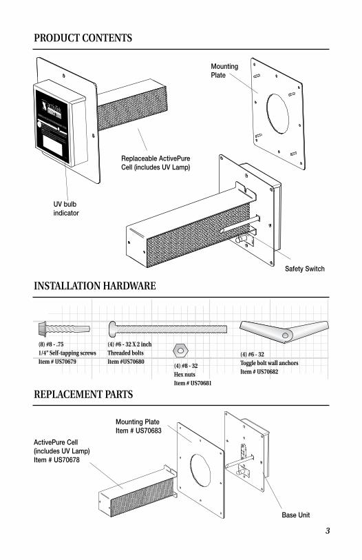
REPLACEMENT PARTS
Base Unit
Mounting PlateItem # US70683
ActivePure Cell(includes UV Lamp)Item # US70678
INSTALLATION HARDwARE
(8) #8 - .751/4” Self-tapping screwsItem # US70679
(4) #6 - 32 X 2 inchThreaded boltsItem #US70680
(4) #6 - 32Toggle bolt wall anchorsItem # US70682
(4) #8 - 32Hex nutsItem # US70681
PRODuCT CONTENTS
UV bulb indicator
Replaceable ActivePure Cell (includes UV Lamp)
Safety Switch
MountingPlate
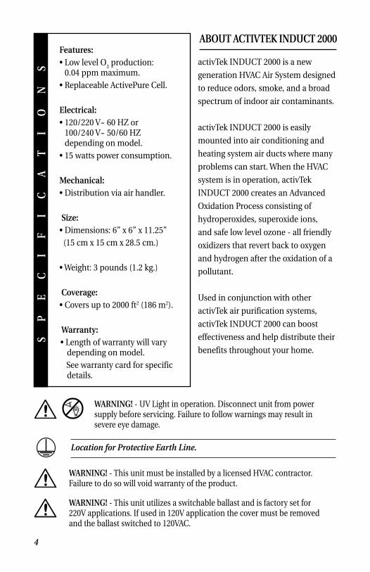
Features:• low level O
3 production:
0.04 ppm maximum.• Replaceable activePure Cell.
Electrical:• 120/220 V~ 60 HZ or
100/240 V~ 50/60 HZ depending on model.
• 15 watts power consumption.
Mechanical:• Distribution via air handler.
Size:• Dimensions: 6” x 6” x 11.25” (15 cm x 15 cm x 28.5 cm.) • weight: 3 pounds (1.2 kg.)
Coverage:• Covers up to 2000 ft2 (186 m2).
warranty:• length of warranty will vary
depending on model. See warranty card for specific
details.
SP
EC
IF
IC
AT
IO
NS
Location for Protective Earth Line.
ABOuT ACTIVTEK INDuCT 2000
activTek INDUCT 2000 is a new
generation HVaC air System designed
to reduce odors, smoke, and a broad
spectrum of indoor air contaminants.
activTek INDUCT 2000 is easily
mounted into air conditioning and
heating system air ducts where many
problems can start. when the HVaC
system is in operation, activTek
INDUCT 2000 creates an advanced
Oxidation Process consisting of
hydroperoxides, superoxide ions,
and safe low level ozone - all friendly
oxidizers that revert back to oxygen
and hydrogen after the oxidation of a
pollutant.
Used in conjunction with other
activTek air purification systems,
activTek INDUCT 2000 can boost
effectiveness and help distribute their
benefits throughout your home.
4
wARNINg! - UV light in operation. Disconnect unit from power supply before servicing. Failure to follow warnings may result in severe eye damage.
wARNINg! - This unit must be installed by a licensed HVaC contractor. Failure to do so will void warranty of the product.
wARNINg! - This unit utilizes a switchable ballast and is factory set for 220V applications. If used in 120V application the cover must be removed and the ballast switched to 120VaC.

Installation Requirements
1. Unit should be installed after the air handler in the
HVaC system.
2. The duct work around the installation area should
be clean and dry to insure proper adhesion of the
gasket materials and any tape used.
3. an approximate 3.5” (8.89 cm) opening will need
to be cut into the existing duct work to install the
unit properly.
RECOMMENDED INSTALLATION TOOLS
INSTALLATION REquIREMENTS
3 1/2” Hole Sawfor wood or metal (recommended)
Drill/Power Driver Phillips Screwdriver 3/8” Drill Bit (if installing into fiberglass ducting with toggle bolts)
You may also need:
Utility Knife Tin Snips (for metal ductwork)
5
Electrical Requirements for 120 volt installation only
• To use a 120 volt plug, be sure to locate the unit within 6 ft. of a standard 120 volt
grounded outlet. long term use of an extension cord is not recommended due to
safety considerations.
• Install a US “B” Ua approved plug onto the blunt cord.
Hardwiring Requirements (All units)
• Permanent wiring of the unit into your HVAC system, or installations
using a 120/220 volt, should be done by a licensed HVAC installer or
electrical contractor only.
wARNINg: CHECK SPECIFICATIONS ON LABELINg BEFORE INSTALLINg.
uNIT IS EITHER: 120V, 220V, or DEPENDINg ON MODEL 100-240V.
For 110 volt units: Black = l1, white = Neutral, Green = Ground
For 220 volt units: Black = l1, white = l2, Green = Ground
For International units: Brown = l1, Blue = l2, Green w/yellow stripe = Ground
Air Handler
Min. 8” x 8”
Max. 6 ft.
11/32” Open-End Wrench 1/4” Nut Driver Bit

6
METAL DuCTwORK INSTALLATION
11. Locate suitable area of duct for installation.
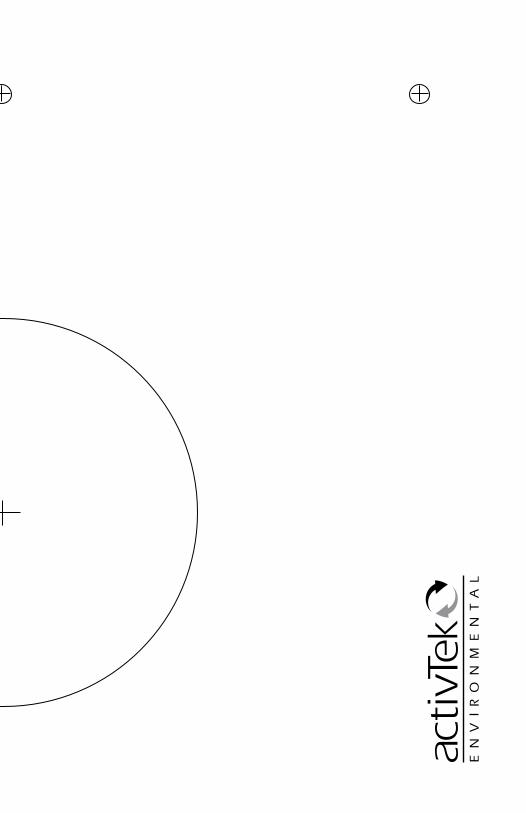
33. Mark location for 3.5” opening using either the mounting plate or included template.
aa. Using template, mark 4 holes on duct.
bb. Drill 4 holes where marked.
cc. Cut between holes using tin snips.
ALTERNATIVE CuTTINg METHOD
44. Cut hole in duct using 3.5” hole saw.
22. Cut away insulation to expose metal duct (if needed).


activTek INDuCT 2000 - CELL HOLE PLACEMENT TEMPLATE
act
ivTe
k IN
DU
CT
2000
M
in. 1
0” x
10”


7
55. Remove backing from mounting plate adhesive gasket.
66. Center openings and press mounting plate onto duct. The adhesive gasket will hold the mounting plate in place.
88. Insert unit into opening. Be sure the air will pass though the ActivePure cell honeycomb matrix.
99. Secure the unit to the mounting plate with (4) #8-32 nuts.
1010. Plug unit into working power receptacle. Hard wiring unit into HVAC system should be done by a licensed HVAC installer or electrical contractor only.
77. Secure the mounting plate using (8) #8 self-tapping screws.
METAL DuCTwORK INSTALLATION (CONTINUED)
3 4
8
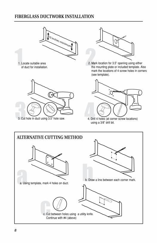
aa. Using template, mark 4 holes on duct.bb. Draw a line between each corner mark.
cc. Cut between holes using a utility knife. Continue with #4 (above)
ALTERNATIVE CuTTINg METHOD
FIBERgLASS DuCTwORK INSTALLATION
1 22. Mark location for 3.5” opening using either the mounting plate or included template. Also mark the locations of 4 screw holes in corners (see template).
3. Cut hole in duct using 3.5” hole saw. 4. Drill 4 holes (at corner screw locations) using a 3/8” drill bit.
1. Locate suitable area of duct for installation.

9
1111. Plug unit into working power receptacle. Hard wiring unit into HVAC system should be done by a licensed HVAC installer or electrical contractor only.
55. Insert (4) 2” Threaded bolts into screw holes at corners of mounting plate. Attach (4) toggle bolt anchors to ends of threaded bolts.
66. Remove backing from mounting plate adhesive gasket.
77. Insert (4) toggle bolts into 3/8” holes in duct. Be sure toggle anchors open after inserting.
88. Center large opening in mounting plate over 3.5” opening in duct and press plate to duct. The adhesive gasket will hold the mounting plate into place. Tighten toggle bolts - DO NOT OVERTIGHTEN.
99. Insert unit into opening. Be sure the air will pass though the ActivePure cell honeycomb matrix.
1010. Secure the unit to the mounting plate with (4) #8-32 nuts.
FIBERgLASS DuCTwORK INSTALLATION (CONTINUED)
Stud

Your activTek INDUCT 2000 unit requires no periodic maintenance beyond normal replacement of the activePure cell every 3 years.
Note: For optimal performance, activTek recommends
the replacement of the ActivePure cell every 3 years, even
if the UV lamp appears to be operating normally.
The UV lamp operation indicator on the face of the unit will glow when the UV lamp is in use. If the indicator does not glow and the unit has power, the activePure cell should be replaced.
UV lamp operation indicator
Please do not throw a used activePure cell into the garbage. The special germicidal UVX bulb used in the activTek INDUCT 2000 contains a very small amount of mercury. You may return your used activePure cell to activTek for proper disposal. Send the used cell post paid to:
DISPOSAL OF THE ACTIVEPuRE CELL
10
activTek EnvironmentalactivePure Disposal55 Marley DriveGreeneville, TN 37743
MAINTENANCE/uV LAMP INDICATOR
Did you forget to register your activTek INDUCT 2000?
By registering, you’ll activate your warranty, and your privacy is guaranteed. Just fill out your warranty card and drop it in the mail.
wARRANTY INFORMATION
This product is of solid state construction and is under warranty by:
activTek Environmental 310 T. Elmer Cox Drive Greeneville, TN 37743
to the original purchaser, depending on model, to be free from defect in materials and workmanship for a limited time. length of warranty will vary depending on model. See warranty card for specific details. If you have any questions concerning your activTek INDUCT 2000, please see your local activTek Distributor.
For help, visit www.activTek.net.
UV LAMP in operation when lit.
WARNING: THIS UNIT IS PROVIDED WITH AN INTERLOCK TO REDUCE THE RISK OF EXCESSIVE ULTRAVIOLET RADIATION. DO NOT DEFEAT ITS PURPOSE OR ATTEMPT TO SERVICE WITHOUT REMOVING COVER COMPLETELY.
WARNING: EYE DAMAGE MAY RESULT FROM DIRECTLY VIEWING THE LIGHT PRODUCED BY THE LAMP USED IN THIS PRODUCT. ALWAYS TURN OFF LAMP OR DISCONNECT UNIT BEFORE OPENING THIS COVER.
COMMERCIAL HVAC AIR PURIFICATION ENHANCEMENT SYSTEM
62-00431-001R
11
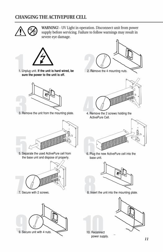
77. Secure with 2 screws. 8
1
33. Remove the unit from the mounting plate. 44. Remove the 2 screws holding the ActivePure Cell.
1. Unplug unit. If the unit is hard wired, be sure the power to the unit is off.
1010. Reconnect power supply.
99. Secure unit with 4 nuts.
22. Remove the 4 mounting nuts.
8. Insert the unit into the mounting plate.
66. Plug the new ActivePure cell into the base unit.
55. Separate the used ActivePure cell from the base unit and dispose of properly.
CHANgINg THE ACTIVEPuRE CELL
wARNINg! - UV light in operation. Disconnect unit from power supply before servicing. Failure to follow warnings may result in severe eye damage.