active chilled beamsashraemontreal.org/archives-sites/his_mtl/text_pdf/chilled_beams... · •...
TRANSCRIPT

Modular Active Chilled Beams
Presented by:
Darren Alexander, P.Eng.

Modular Active Chilled Beams

Current System Solutions• Fan Coil Units -
Medium/High energy, medium noise solution. Output = 100-200 w/m2 (32-64 Btuh/ft2) Adaptable solution.
• VAV system -Low energy, low/medium noise solution.Output = 100-200 w/m2 (32-64 Btuh/ft2) Most efficient all air system.
• VRV system (Variable Refrigerant Volume) -High energy, medium noise solution. Output = 150-200 w/m2 (48-64 Btuh/ft2).Potential for high maintenance costs.
• Chilled Beams -Low energy, low noise solution. Output = 100-394W/m2 (32-125 Btuh/ft2) Extremely low maintenance costs.

Reduction In Overall System Power
ConventionalHVAC System
Radiant Cooling & Chilled Beams*
Other Loads
Air Transport load
Load From Lights
Fan & Motor
100% Peak Power
57.7%37.5%
18.8%
9.3%
34.4% 34.4%
1.9%9.4%7.5%1.5% Pumps
Chiller62.5%
Percentages relative to overall peak power for the conventional systemFigure from: Centre For Building Science News, Lawrence Berkeley
Laboratory, “Hydronic Radiant Cooling Systems”, Fall 1994.* Figure does not include additional fan energy associated with
developing pressure for active chilled beam operation.

Active Chilled Beams

Potential Energy Savings

Potential Energy Savings

Operation

Operation

Operation

Operation
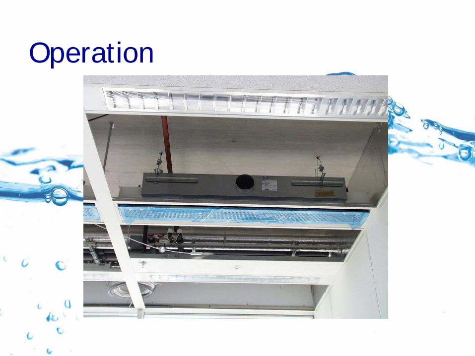
• Hanging rails with brackets for easy mounting
• 12mm (0.5”) water connections
• No moving parts• Easy access from front,
where room air enters
Operation
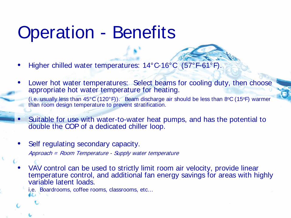
Operation - Benefits
• Higher chilled water temperatures: 14°C-16°C (57°F-61°F).
• Lower hot water temperatures: Select beams for cooling duty, then choose appropriate hot water temperature for heating. (i.e. usually less than 45°C (120°F)). Beam discharge air should be less than 8oC (15oF) warmer than room design temperature to prevent stratification.
• Suitable for use with water-to-water heat pumps, and has the potential to double the COP of a dedicated chiller loop.
• Self regulating secondary capacity. Approach = Room Temperature - Supply water temperature
• VAV control can be used to strictly limit room air velocity, provide linear temperature control, and additional fan energy savings for areas with highly variable latent loads.i.e. Boardrooms, coffee rooms, classrooms, etc…

Possible Operating Conditions
Air dew point 10°C, (50°F)Water temperature 14°C, (57°F)Dehumidification=
0.002 lbs per lbs of dry air
Air dew point 12°C, (54°F)Water temperature 16°C, (61°F)Dehumidification=
0.0025 lbs per lbs of dry airPsychrometric Chart

Critical Room Air Velocities
• P1 only critical up against the wall
• P2 drops rapidly moving into the room
• P3 = ½ at 1m height

Air Distribution Chart
24.5 °C (76.0 °F) Room temperature, at <0.5T allows 0.4m/s room air velocity23.9 ° C (75.0 °F) Room temperature, at <0.45T allows 0.4m/s room air velocityTypical diffuser comfort line @ 0.9 T moving air High performance chilled beam comfort line @ 0.45 T moving air
COMFORTABLE
-1.4-1.3-1.2-1.1
-1-0.9-0.8-0.7-0.6-0.5-0.4-0.3-0.2-0.1
5 15 25 35 45
Average room air velocity cm/s
Mov
ing
air
T (o C
)
22.2°C(72°F)
22.8°C(73°F)
23.3°C(74°F)
23.9°C(75°F)
24.5°C(76°F)
25.0°C(77°F)
25.6°C(78°F)
26.1°C(79°F)
26.7°C(80°F)
(10 fpm) (30 fpm) (50 fpm) (70 fpm) (90 fpm)
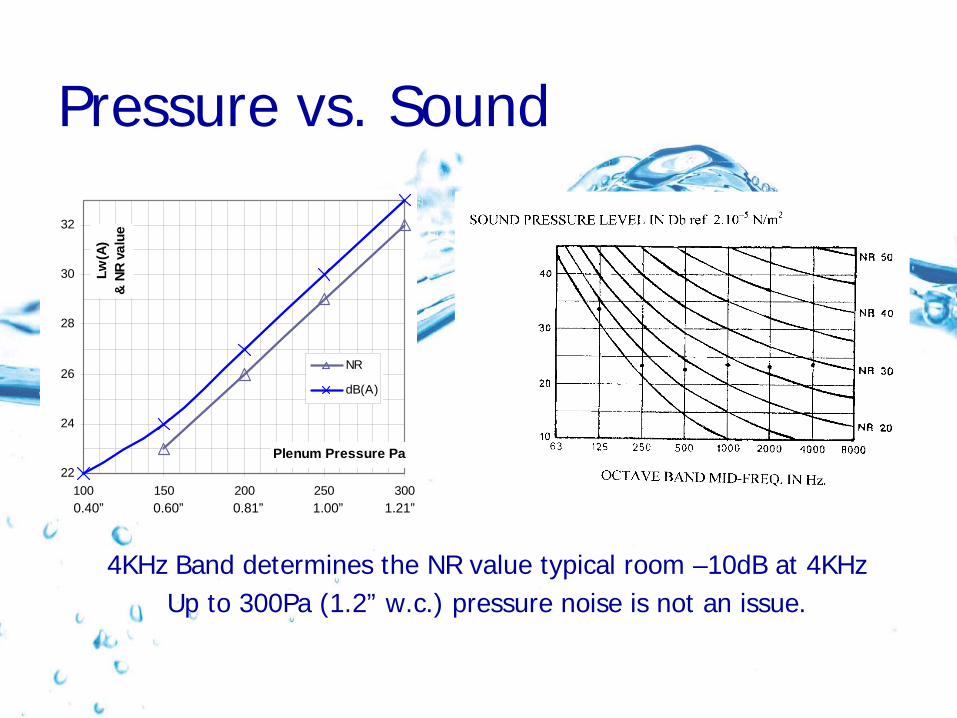
Pressure vs. Sound
22
24
26
28
30
32
100 150 200 250 300
Plenum Pressure Pa
Lw(A
)&
NR
valu
e
NR
dB(A)
0.40” 0.60” 0.81” 1.00” 1.21”
4KHz Band determines the NR value typical room –10dB at 4KHzUp to 300Pa (1.2” w.c.) pressure noise is not an issue.

Chilled Beam Capacity vs. Primary Air Volume
Values for a 600mm x 1200mm (2’x4’) Beam
5
10
15
20
25
30
35
40
100 200 300 400 500 600 700 800
Secondary Capacity [W]
Air
Volu
me
[l/s]
A-DT 8A-DT 10B-DT 8B-DT 10C-DT 8C-DT 10D-DT 8D-DT 10
85 cfm
74 cfm
64 cfm
53 cfm
42 cfm
32 cfm
21 cfm
11 cfm
341 682 636 848 1706 1272 2388 2730Btuh

Chilled Beam Capacity vs. Primary Air Volume
50
70
90
110
130
150
170
190
210
230
250
150 200 250 300 350 400 450 500 550 600 650 700
Secondary Capacity [W]
Plen
um p
ress
ure
[Pa]
A-DT 8A-DT 10B-DT 8B-DT 10C-DT 8C-DT 10D-DT 8D-DT 10
512
1.00”
0.93”
0.85”
0.77”
0.60”
0.69”
0.44”
0.52”
0.28”
0.36”
0.20”
Values for a 600mm x 1200mm (2’x4’) Beam
682 853 1024 1194 1365 1535 1706 1877 2047 2218 2388Btuh
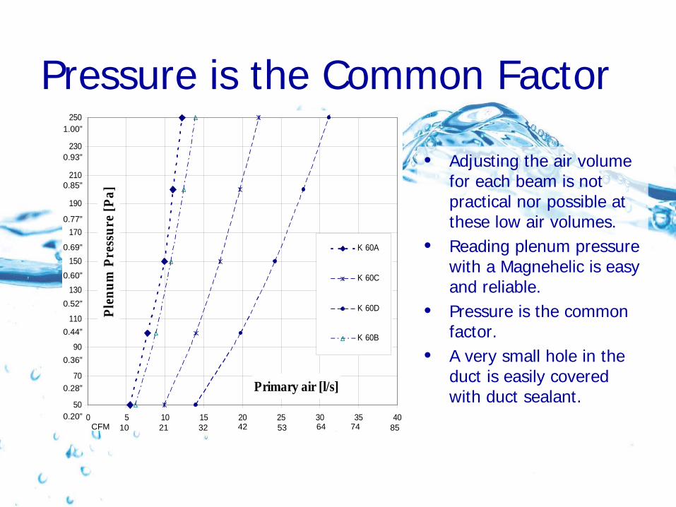
Pressure is the Common Factor
• Adjusting the air volume for each beam is not practical nor possible at these low air volumes.
• Reading plenum pressure with a Magnehelic is easy and reliable.
• Pressure is the common factor.
• A very small hole in the duct is easily covered with duct sealant.50
70
90
110
130
150
170
190
210
230
250
0 5 10 15 20 25 30 35 40
Primary air [l/s]
Plen
um P
ress
ure
[Pa]
K 60A
K 60C
K 60D
K 60B
1.00”
0.93”
0.85”
0.77”
0.69”
0.60”
0.44”
0.36”
0.28”
0.20”
0.52”
10 21 32 42 53 64 74 85CFM

Ducting for Equal Static PressurePt = Ps + Pv
Pt = total pressure [Pa] (”w.c.)Ps = static pressure [Pa] (”w.c.)Pv = velocity pressure [Pa] (”w.c.)• If velocity pressure is kept negligibly low, then the same static pressure will
hold throughout the duct. ( i.e. Only if transport loss can be neglected).
Pv = 0,5 x r x v2
Pv = velocity pressure [Pa] (”w.c.)r = air density [1.2 kg/m3] (0.075 lbs/ft3)v2 = air velocity [m/s] (fpm)
At < 3m/s (590 fpm) duct air velocity Pv < 5.4[Pa] (0.02”w.c.)At < 3m/s (590 fpm) transport Ø = 125mm (5”) < 1Pa/m (0.001”w.c/ft.)Ø = 200mm (8”) < 0.6Pa/m (.0007”w.c./ft.)
• Low air volumes required for beams makes using round ducting practical and low air velocity achievable.

Controls
Water & Air

On/Off Water Control
• Can be used for large zones• ON/OFF is only for secondary capacity • Ventilation remains• Required with interlock for opening
windows, or dew point sensor on chilled water supply.

Self-Regulating – Simple Controls!
Self Regulating Approach = Room Temperature – Supply water temperature.
Example: Room temp 75°F (24°C), Water temperature 61°F (16°C)Therefore Approach = 14oF (8K), Capacity = X
As Room temp drops to 68°F (20°C), Water temperature 61°F (16°C),Therefore Approach = 7oF (4K), Capacity = ½ X
T water/room
Seco
ndar
y ca
paci
ty
400W
200W
(1365 Btuh)
(682 Btuh)

Proportional Water Flow Control
0 50 100
Water l/h
Cap
acity
T water/room
Sec
onda
ry C
apac
itySingle Circuit Water Flow
- non-linear, possible operation issues, likely expensive for small
circuits.
Turbulent Flow
Laminar Flow
Temperature Controlled Water
- Usually restricted to floor plates.

Pressure Control
• Setting up for constant volume control is feasible.
• Using variable static pressure gives non linear control; hence instability, tight control with static pressure is not practical.Static Pressure
Tota
l cap
acity

VAV Control
• Max. used to limit room air velocity. Usually no more than 1.2” w.c.(300 Pa)
• Self regulating enables large zones• VAV only for ‘fresh air’• VAV diversity advantage retained• Linear capacity control gives tight
temperature control
P-band allows even more air movement
Primary air volume
Tota
l cap
acity
•• Use duct pressure as velocity pressure• Min. 0.3” (75 Pa) for all beams

Installation Cost Comparison 3 kW (1 ton) Nominal
FAN COIL• Fan Coil Unit + diffuser• Mounting FCU + diffuser• 3x spigot connections• 1x Water connection and
insulation• 1 x Condensation drainage• 120 V AC connection• 1 x Unit Controller, 4 port
valves, actuators and room temp. sensor
CHILLED BEAMS• Beams 3 units x 2.1m • Mounting 3 Beams• 3x spigot connections• 3x Water connections return
water needs no insulation• No condensate drainage• No electrical connections• Very simple terminal controls
Special duct consideration for beams:USE LARGER DOWNSTREAM DUCTING TO MAINTAIN STATIC PRESSURE

Installation Cost Comparison 3 kW (1 ton) Nominal
Operational savings with Beams:
• 50% electric power for the chiller with 16ºC (61ºF) water, or ground water, for cooling
• Reduced primary air with VAV• Tight temperature control where required, with VAV• No secondary fan power• No moving parts to maintain• No filters to change

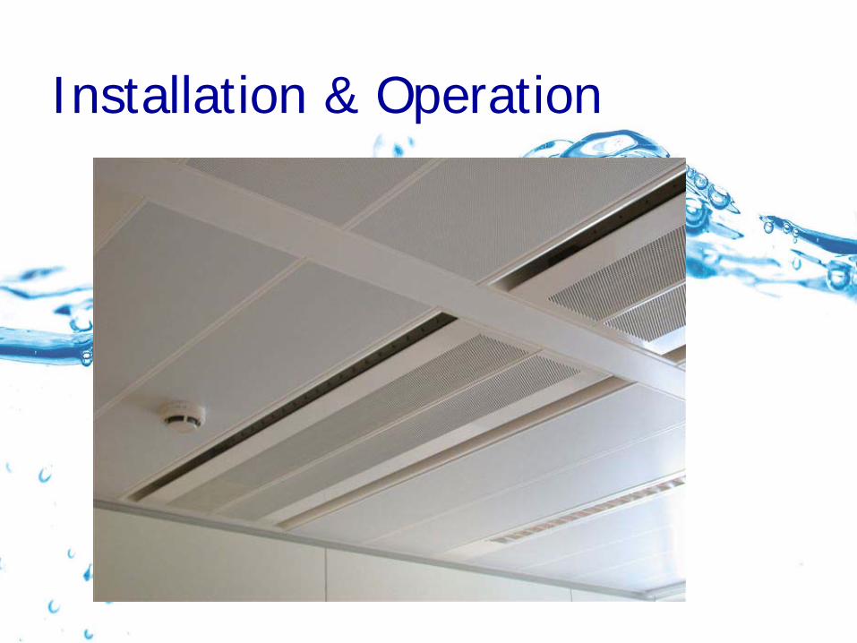
Installation & OperationInstallation
• Easy mounting with hanging rails and brackets
• No moving parts• Very little maintenance• Easy access from the front for coil
cleaning.• No electrical connections• Inexpensive terminal controls
Operation• High chilled water temperature
14-16°C (57-61°F)• Primary ‘fresh’ air quantity tailored
to suit ventilation requirements.• Self regulating• VAV for tight temperature control

Installation & Operation

Installation & Operation
Installation & Operation

Conclusions
• Chilled beams are the ultimate low energy, low noise air conditioning solution.
• High standards of indoor climate can be achieved with excellent air distribution and control.
• Highly variable loads can be addressed using VAV on the Primary air supply.
• Simple commissioning of both air and water.
• Practically no maintenance required.
• DOAS Information: http://doas-radiant.psu.edu.leed.html

Documentation
• Air diffusion colour printed documentation• Selection program for 600mm wide (24”)• PDF product documentation for 600mm (24”) wide beams
– Features benefits & operations– Drawings– Primary capacity graph– Secondary capacity graph– Static pressure graphs– Water pressure drop values– Sound power levels at various pressures– Distances to observe for room air velocity
Documentation
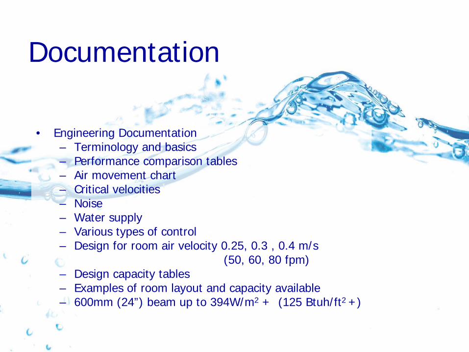
• Engineering Documentation– Terminology and basics– Performance comparison tables– Air movement chart– Critical velocities– Noise– Water supply– Various types of control– Design for room air velocity 0.25, 0.3 , 0.4 m/s
(50, 60, 80 fpm)– Design capacity tables– Examples of room layout and capacity available – 600mm (24”) beam up to 394W/m2 + (125 Btuh/ft2 +)