aco eurobar concast iron technical documentationf.licitationen.dk/2zg48xcwulbzac8a.pdf ·...
TRANSCRIPT

Factory standard 0-200.003
Based on the
material designations
in EN 16482
Bezeichnung
EN-GJS-400-18C-LTACO Eurobar® GGG-40.3 LT
EN-GJS-400-18C-RTACO Eurobar® GGG-40.3 RT
ACO Eurobar® Concast Iron
Technical Documentation

2
ACO Eurobar® Concast Iron: Technical Documentation
It gives us great pleasure to present the new ACO Eurobar® works standard.We at ACO Eurobar, a specialist for continuous-cast iron, have revised the Technical Documentation pertinent to our high-quality continuous-cast iron bar products.
There has for some time existed a need for a standard for continuous-cast irons. Apart from providing a guidance for manufacturers, such a standard would facilitate prepara-tion of offers while at the same time constituting a basis for comparison between ma-terials from various sources. Hence, it is especially gratifying that a European standard “EN 16482 – Cast Iron – Continuous Casting” is now agreed upon and available. It is the publication of this new standard that is the primary driving force for us to amend the Technical Documentation that you are now reading.
4HEÏlRSTÏSECTIONÏOFÏTHEÏ4ECHNICALÏ$OCUMENTATIONÏFURNISHESÏAÏDETAILEDÏDESCRIPTIONÏOFÏTHEÏACO Eurobar programme in relation to product characteristics and quality with particular emphasis on the changes which accrue from the instigation of EN 16482. Further, the extent to which ACO Eurobar products exceed the requirements in the new standard is emphasised. Examples of assured properties over and above what is stipulated in EN 16482 are:
Guaranteed levels of Brinell Hardness;Ï 'RAPHITEÏSHAPEÏSPECIlCATION�Ï 1UANTITATIVEÏSPECIlCATIONSÏFORÏMATRIXÏMICROSTRUCTURE� For some products, guarantees for minimum levels of Charpy-V impact energy.
These supplementary guarantees ensure that you are supplied with a product which ex-ceeds the regular market standard.
The second part of the document focusses upon some typical features and characteris-TICSÏOFÏCONTINUOUS CASTÏIRONSÏANDÏTHEIRÏINmUENCEÏONÏMECHANICALÏPROPERTIES�Ï4HEÏAIMÏHEREÏis to provide an unambiguous interpretation so that the basis for eventual stipulations additional to those in EN 16482 is well-founded from the point of view of users as well as manufacturers.
In addition to supplying a product with outstanding quality, which at least conforms to and in many respects exceeds the requirements of the new EN 16482 standard, you MAYÏRESTÏASSUREDÏTHATÏOURÏSPEEDÏOFÏRESPONSEÏANDÏDELIVERY�ÏmEXIBILITYÏANDÏABSOLUTEÏATTEN-tion to customer demands remain unchanged. If you have any questions concerning this revised Technical Documentation, you are very welcome to contact us directly.
We look forward to a continued fruitful collaboration.
Your team at ACO Eurobar.

ACO Eurobar® Concast Iron: Technical Documentation
3
Table of contents
I. ACO Eurobar® concast iron: Technical Documentation
General: ........................................................................................................................... PageComparison of EN 16482 and ACO Eurobar® material designations incl. colour coding ...................... 4 Sample positions (samples taken from both material groups) ........................................................... 5 )NSTRUCTIONSÏONÏHANDLINGÏTHEÏSPECIlCATION ....................................................................................... 6
Cast iron with grey cast iron graphite: 1. Mechanical properties ............................................................................................................ 61.1 Tensile strength/Brinell hardness ............................................................................................. 6 2. Microstructure ....................................................................................................................... 7 2.1 Matrix ................................................................................................................................... 7 2.2 Graphite structure as per EN ISO 945 ..................................................................................... 7 2.3 Matrix structure ..................................................................................................................... 7 2.4 Chemical composition ............................................................................................................ 7 3. As-cast dimensional tolerances ............................................................................................... 83.1 General tolerances (dimensions) .............................................................................................. 83.2 Straightness .......................................................................................................................... 83.3 Ovality and curvature ............................................................................................................. 84. Minimum machining allowances ............................................................................................... 9
Cast iron with nodular graphite: 5. Mechanical properties ............................................................................................................ 105.1 Tensile strength/Brinell hardness ............................................................................................. 105.2 V-notch impact energy EN-GJS-400-18C-LT and RT .................................................................... 115.3 V-notch impact energy EN-GJS-350-22C-LT and RT .................................................................... 115.4 Additional information: elasticity modulus and fracture toughness ............................................... 116. Microstructure ....................................................................................................................... 126.1 Matrix ................................................................................................................................... 126.2 Graphite structure as per EN ISO 945 ..................................................................................... 126.3 Matrix structure ..................................................................................................................... 126.4 Chemical composition ............................................................................................................ 127. As-cast dimensional tolerances ............................................................................................... 137.1 General tolerances (dimensions) .............................................................................................. 137.2 Straightness .......................................................................................................................... 137.3 Ovality and curvature ............................................................................................................. 138. Minimum machining allowances ............................................................................................... 14
9. Limits of admissibility........... .................................................................................................. 15 9.1 Surface defects ..................................................................................................................... 159.2 Inhomogeneities .................................................................................................................... 1510. Bibliography .......................................................................................................................... 15
II. Concast materials: typical features
Introduction ................................................................................................................................. 16Process-related features ............................................................................................................... 16Draw marks at the strand surface ................................................................................................. 16Machining allowance at the strand surface ..................................................................................... 161. Material ................................................................................................................................ 171.1 Mechanical properties ............................................................................................................ 171.2 Microstructural defects (microscopic) ...................................................................................... 171.3 Inhomogeneities (macroscopic) ............................................................................................... 192. Production ............................................................................................................................ 192.1 The production process .......................................................................................................... 19���Ï'EOMETRYÏDElNITIONSÏ ............................................................................................................. 203. Machining ............................................................................................................................. 213.1 Work order ............................................................................................................................ 213.2 Semis ................................................................................................................................... 213.3 Finished parts: geometry ........................................................................................................ 213.4 Corrosion .............................................................................................................................. 214. Bibliography .......................................................................................................................... 21
III. About us: ACO Eurobar – ACO Guss – The ACO Group ................................................. 22

ACO Eurobar® Concast Iron: Technical Documentation
4
Material designation as per EN 16482 Material designation as per ACO Eurobar®
Colour coding*ACO Eurobar®
Designation Number
EN-GJL-150C 5.1102 GG-Fgrey/red
EN-GJL-250C 5.1203 GG-FPgrey
EN-GJL-300C 5.1308 GG-Pblack
Material designation as per EN 16482
Material designation as per ACO Eurobar® Matrix Colour coding*
ACO Eurobar®
Designation Number
EN-GJS-350-22C-LT 5.3120 GGG 35.3 LT ferriticyellow/red
EN-GJS-350-22C-RT 5.3121 GGG 35.3 RT ferriticyellow/red
EN-GJS-350-22C 5.3122 GGG 35.3 ferriticyellow/red
EN-GJS-400-18C-LT 5.3123 GGG 40.3 LT ferriticyellow/red
EN-GJS-400-18C-RT 5.3124 GGG 40.3 RT ferriticyellow/red
EN-GJS-400-18C 5.3125 GGG 40.3 ferriticyellow/red
EN-GJS-400-15C 5.3126 GGG 40 ferriticyellow/red
EN-GJS-500-7C 5.3203 GGG 40/50 ferritic-pearliticyellow
EN-GJS-500-14C 5.3129 EN-GJS 500-14 ferriticgreen
EN-GJS-600-3C 5.3204 GGG 60 pearlitic-ferriticblue
EN-GJS-700-2C 5.3303 GGG 70 mainly pearliticwhite
Comparison of EN 16482 and ACO Eurobar® material designations incl.
colour coding
ACO Eurobar® cast iron with grey cast iron and nodular graphite
*) All color codes are based on the international RAL color code. We are happy to inform you on request which RAL colors are used by ACO Eurobar. If
desired, we can supply the appropriate color as spray paint.

ACO Eurobar® Concast Iron: Technical Documentation
5
Sample-taking
If D/4 and/or H/4 <_ 10 mm, take samples directly at the outer contour. D = Diameter H = Height W = Width
Round
Sample locations
Square Rectangular
Half round

ACO Eurobar® Concast Iron: Technical Documentation
6
In rectangular cross-sections, the smallest dimension shall be the reference strand dimension. In round bars, the diameter shall be the reference dimension.
Example (explanation)
Material: EN-GJS-400-15C
Dimensions: rectangle 130 x 90 x 3150 mm
Controlling strand dimension 90 mm
Notes and/or instructions regarding this specification:
Material designation Strand diameter
D
0,2 % Proof stress
Rp 0,2
MPa
Tensile strength
Rm
MPa
Elongation A
%
Brinell hardness
HBW
Designation Number [mm] min. min. min. min. max.
EN-GJS-400-15Ca)
5.3126
20 < D <_ 60 250 400 15
130 180 60 < D <_ 120 250 390 14
120 < D <_ 400 240 370 11
Target specifications (extract from table 5.1)
Concast iron with grey cast iron graphite
1. Mechanical properties, cast iron with grey cast iron graphite
1.1 Tensile strength/Brinell hardness
Material designation Strand diameter
D
Tensile strength
Rm
MPa
Brinell hardness a)
HBW
Designation Number [mm] min. min. max.
EN-GJL-150C 5.1102
20 < D <_ 50 110
110 180 50 < D <_ 100 100
100 < D <_ 200 90
200 < D <_ 400 80
EN-GJL-250C 5.1203
20 < D <_ 50 195
170 240 50 < D <_ 100 180
100 < D <_ 200 165
200 < D <_ 400 155
EN-GJL-300C 5.1308
20 < D <_ 50 220
200 290 50 < D <_ 100 205
100 < D <_ 200 195
200 < D <_ 400 185
a) Brinell hardness guaranteed in deviation from EN 16482
a) Brinell hardness guaranteed in deviation from EN 16482

ACO Eurobar® Concast Iron: Technical Documentation
7
Material designation Matrix
EN-GJL-150C ferritic
EN-GJL-250C pearlitic-ferritic
EN-GJL-300C mainly pearlitic
2. Microstructure
2.1 Matrix
Sample-taking locations Strand dimensions [mm] &Q@OGHSDÏBNMkFTQ@SHNM
Surface zone, Sz allType I, Configuration D(max. 15% E and A)
Centre H and/or D <_ 100Type I, Configuration A (max. 20% B, D and E)
Centre H and/or D > 100 <_ 150Type I, Configuration A (max. 20% B, D and E)
Centre H and/or D > 150Type I, Configuration A (max. 20% B, D and E)
# CONlGURATIONÏGRAPHITEÏISÏNOTÏADMISSIBLE�
Material designationPearlite content [%]
Surface zone Centre
EN-GJL-150C <_ 10 <_ 10
EN-GJL-250C > 10 > 60
EN-GJL-300C > 10 > 80
Chemical compositions are subject to applicable factory analysis standards.
2.2 Graphite structure as per EN ISO 945
2.3 Matrix structure
2.4 Chemical composition

ACO Eurobar® Concast Iron: Technical Documentation
8
Diameter [D]/Height [H]/Width [B]
[mm]
Tolerance
[mm]
<_ 100 +_ 1,0
> 100 <_ 150 +_ 1,5
> 150 <_ 300 +_ 2,0
> 300 +_ 3,0
3. As-cast dimensional tolerances
3.1 General tolerances (dimensions)
Length [mm]
l
Maximum deviation from the straight [mm]
as-cast annealed
1 000 2 3
2 000 4 6
3 000 6 9
3.2 Straightness
Illustration:
Diameter [D]/ Height [H]/Width [B]
[mm]
Maximum ovality allowance (round dimensions)
[mm]
Maximum curvature allowance (rectangular and square dimensions)
[mm]
20 < D < 50 - 5
50 < D < 100 1 7
100 < D < 200 2 10
200 < D < 300 4 12
300 < D < 400 5 15
D > 400 to be agreed
3.3 Ovality and curvature
BIllustrations: Ovality Curvature

ACO Eurobar® Concast Iron: Technical Documentation
9
Strand diameter D or strand width B
a), b)
Minimum machining allowance relative to the radius or half the width of the strand
[mm] circular [mm] rectangular [mm]
20 < D oder B < 50 2,0 2,5
50 < D oder B < 100 3,0 3,5
100 < D oder B < 200 4,0 4,5
200 < D oder B < 300 6,0 6,5
300 < D oder B < 400 7,0 7,5
400 < D oder B < 500 9,0 9,5
500 < D oder B < 650 11,0 11,5
a) In rectangular castings, the width is the longest cross-sectional dimension.b) Machining allowances are specified relative to the radius or half the width of the strand.
4. Minimum machining allowances
In round bars, the diameter is the reference dimension. In rectangular bars, machining allowances may vary depending on height and width.
Example (explanation rectangular dimensions)
Material: EN-GJL-250C
Dimensions: rectangular 130 x 90 x 3150 mm
Minimum machining allowance Width 130 mm = 4,5 mm per side Height 90 mm = 3,5 mm per side
Notes and/or instructions regarding this specification:
In rectangular strands, therefore, machining allow-
ances may actually vary from side to side.

ACO Eurobar® Concast Iron: Technical Documentation
10
5.1 Tensile strength/Brinell hardness
Concast iron with nodular graphite
5. Mechanical properties, cast iron with nodular graphite
Material designation Strand diameter
D
0,2 % Proof stress
Rp 0,2MPa
Tensile strength
RmMPa
Elongation
A%
Brinell hardness
HBW
c)
Designation Number [mm] min. min. min. min. max.
EN-GJS-350-22C-LT 5.3120
20 < D <_ 60 220 350 22
110 150 60 < D <_ 120 210 330 18
120 < D <_ 400 200 320 15
EN-GJS-350-22C-RT 5.3121
20 < D <_ 60 220 350 22
110 150 60 < D <_ 120 220 330 18
120 < D <_ 400 210 320 15
EN-GJS-350-22C 5.3122
20 < D <_ 60 220 350 22
110 150 60 < D <_ 120 220 330 18
120 < D <_ 400 210 320 15
EN-GJS-400-18C-LT 5.3123
20 < D <_ 60 240 400 18
130 180 60 < D <_ 120 230 380 15
120 < D <_ 400 220 360 12
EN-GJS-400-18C-RT 5.3124
20 < D <_ 60 250 400 18
130 180 60 < D <_ 120 250 390 15
120 < D <_ 400 240 370 12
EN-GJS-400-18C 5.3125
20 < D <_ 60 250 400 18
130 180 60 < D <_ 120 250 390 15
120 < D <_ 400 240 370 12
EN-GJS-400-15C a)
5.3126
20 < D <_ 60 250 400 15
130 180 60 < D <_ 120 250 390 14
120 < D <_ 400 240 370 11
EN-GJS-500-14C a), b)
5.3129
20 < D <_ 60 400 500 14
180 220 60 < D <_ 120 390 480 12
120 < D <_ 400 360 470 10
EN-GJS-500-7C a)
5.3203
20 < D <_ 60 320 500 7
150 240 60 < D <_ 120 300 450 7
120 < D <_ 400 290 420 5
EN-GJS-600-3C a)
5.3204
20 < D <_ 60 370 600 3
200 290 60 < D <_ 120 360 600 2
120 < D <_ 400 340 550 1
EN-GJS-700-2C a)
5.3303
20 < D <_ 60 420 700 2
235 310 60 < D <_ 120 400 700 2
120 < D <_ 400 380 650 1
a) Depending on the process applied, these materials may contain free carbides in small quantities.b) Solid-solution strengthened ferritic cast iron with nodular graphite.c) Brinell hardness guaranteed in deviation from EN 16482.

ACO Eurobar® Concast Iron: Technical Documentation
11
Material designation Dimensions:Diameter [D]/
Height [H]/Width [B]
Minimum v-notch impact energy (J)
at -20°C+/-2°C
Minimum v-notch impact energy (J)
at 23°C +/-5°C
[mm] Mean of 3 tests Single value Mean of 3 tests Single value
EN-GJS-400-18C-LT 20 < D <_ 120120 < D <_ 400
1210
97
EN-GJS-400-18C-RT 20 < D <_ 120120 < D <_ 400
1412
119
5.2 V-notch impact energy EN-GJS-400-18C-LT and RT
Material designation Dimensions: Diameter [D]/
Height [H]/Width [B]
Minimum v-notch impact energy (J)
at -40°C+/-2°C
Minimum v-notch impact energy (J)
at 23°C +/-5°C
[mm] Mean of 3 tests Single value Mean of 3 tests Single value
EN-GJS-350-22C-LT 20 < D <_ 120120 < D <_ 400
1210
97
EN-GJS-350-22C-RT 20 < D <_ 120120 < D <_ 400
1714
1411
5.3 V-notch impact energy EN-GJS-350-22C-LT and RT
5.4 Additional information: elasticity modulus and fracture toughness
Material designation Test temperature 0,2 % Proof stress
Rp 0,2MPa
Tensile strength
RmMPa
Elongation
A%
Elasticity modulus
EGN/m2
Fracture toughness
KIMPa�m
a) a) a) b) a), c)
EN-GJS-400-18C-LTRT 256 372 22,5 169 43,7
- 20 °C 277 397 19,5 170 -
EN-GJS-400-18CRT 300 424 26 171 50,3
- 20 °C 330 453 23,5 172 -
EN-GJS-500-7CRT 354 533 15,0 177 41,0
- 20 °C 382 558 16 178 -
EN-GJS-500-14CRT 391 504 19,5 173 46,5
- 20 °C 421 535 20,5 175 -
EN-GJS-600-3CRT 448 782 7,0 166 23,3 (KIC)
- 20 °C 473 753 3,0 167 -
a) Mean of 3 measurements after fractureb) Mean of 5 measurementsc) Tested in conformance with ISO 12135, test bar SE (B) 10
Samples of mechanical properties measured on a strand with a diameter of 160 mm.

ACO Eurobar® Concast Iron: Technical Documentation
12
Sample-taking locations Strand dimensions [mm] &Q@OGHSDÏBNMkFTQ@SHNMÏ
Surface zone, Sz all > 80 % types VI + V
Centre H bzw. D <_ 100 > 95 % types VI + V
Centre H bzw. D > 100 <_ 150 > 95 % types VI + V
Centre H bzw. D > 150 > 90 % types VI + V
Graphite belonging to types I and II is not admissible across the entire section.
Graphite belonging to type III is admissible up to 5% max. across the entire section.
Graphite belonging to type IV is admissible up to 10% max. at the centre of strands measuring > 150 mm H and/or D
Material designationPearlite content [%]
Surface zone Centre
EN-GJS-350-22C-LT <_ 10 <_ 10
EN-GJS-350-22C-RT <_ 10 <_ 10
EN-GJS-350-22C <_ 10 <_ 10
EN-GJS-400-18C-LT <_ 10 <_ 10
EN-GJS-400-18C-RT <_ 10 <_ 10
EN-GJS-400-18C <_ 10 <_ 10
EN-GJS-400-15C <_ 10 <_ 10
EN-GJS-500-14C a), b) <_ 10 <_ 10
EN-GJS-500-7C a) > 10 > 20 <_ 80
EN-GJS-600-3C a) > 10 > 60
EN-GJS-700-2C a) > 10 > 80
a) Depending on the method employed, these materials may contain free carbides in small quantities.
b) Solid-solution strengthened ferritic cast iron with nodular graphite.
Chemical compositions are subject to applicable factory standards for analysis.
6.2 Graphite formation as per EN ISO 945
6.3 Matrix structure
6.4 Chemical composition
6.1 Matrix
6. Microstructure
Material designation Matrix
EN-GJS-350-22C-LT ferritic
EN-GJS-350-22C-RT ferritic
EN-GJS-350-22C ferritic
EN-GJS-400-18C-LT ferritic
EN-GJS-400-18C-RT ferritic
EN-GJS-400-18C ferritic
EN-GJS-400-15C ferritic
EN-GJS-500-14C a), b) ferritic
EN-GJS-500-7C a) ferritic-pearlitic
EN-GJS-600-3C a) pearlitic-ferritic
EN-GJS-700-2C a) mainly pearlitic
a) Depending on the method employed, these materials may contain free carbides in small quantities.
b) Solid-solution strengthened ferritic cast iron with nodular graphite.

ACO Eurobar® Concast Iron: Technical Documentation
13
Diameter [D]/Height [H]/Width [B]
[mm]
Tolerance[mm]
<_ 100 +_ 1,0
> 100 <_ 150 +_ 1,5
> 150 <_ 300 +_ 2,0
> 300 +_ 3,0
7. As-cast dimensional tolerances
7.1 General tolerances (dimensions)
Lenght [mm]
l
Maximum deviation from the straight [mm]
as-cast annealed
1 000 2 3
2 000 4 6
3 000 6 9
7.2 Straightness
Illustration:
Strand DiameterD
[mm]
Maximum ovality allowance
[mm]
Maximum curvature allowance
[mm]
20 < D < 50 5
50 < D < 100 2 7
100 < D < 200 3 10
200 < D < 300 4 12
300 < D < 400 5 15
D > 400 to be agreed
7.3 Ovality and curvature
Illustrations: Ovality Curvature

ACO Eurobar® Concast Iron: Technical Documentation
14
Strand diameter D or strand width B
a)
Minimum machining allowance relative to the radius or half the width of the strand
[mm] circular [mm] rectangular [mm]
20 < D oder B < 50 3,0 3,5
50 < D oder B < 100 4,0 4,5
100 < D oder B < 200 5,0 5,5
200 < D oder B < 300 7,0 7,5
300 < D oder B < 400 8,0 8,5
400 < D oder B < 500 10,0 10,5
500 < D oder B < 650 12,0 12,5
a) In rectangular bars, width is the longest dimension of the cross-section.
8. Minimum machining allowances
In round bars, the diameter shall be the reference dimension. In rectangular bars, machining allowances may vary depending on height and width.
Example (explanation rectangular dimensions)
Material: EN-GJS-400-15C
Dimensions: rectangular, 130 x 90 x 3150 mm
Minimum machining allowance Width 130 mm = 5.5 mm per side Height 90 mm = 4.5 mm per side
Notes and/or instructions regarding this specification:

ACO Eurobar® Concast Iron: Technical Documentation
15
Scoring and drawing-step overlaps are admissible only within the range of the machining allowance.
9. Limits of admissibility
9.1 Surface defects
Macroscopically visible defects exposed by machining that are of no functional relevance do not constitute a cause for complaint.
9.2 Inhomogeneities
[1] DIN EN 1561, Gießereiwesen – Gusseisen mit Lamellengraphit[2] DIN EN 1563, Gießereiwesen – Gusseisen mit Kugelgraphit[3] Herfurth, K.: Gusseisen-Strangguss für eine innovative Teilefertigung, Konstruieren + Gießen 20 (2005)
Nr. 3, S. 2-17.1) [4] Herfurth, K.: Gusseisen-Strangguss, Qualitätsbewertung, Konstruieren + Gießen 33 (2008) Nr. 2, S. 11-20.2)[5] EN 1560, Gießereiwesen – Bezeichnungssystem für Gusseisen – Werkstoffkurzzeichen und Werkstoffnummern;�=Ï Ï%.Ï)3/Ï�����Ï'EOMETRISCHEÏ0RODUKTSPEZIlKATIONÏ�'03ÏnÏ'EOMETRISCHEÏ4OLERIERUNGÏnÏ4OLERIERUNGÏVONÏ&ORM�Ï
Richtung, Ort und Lauf (ISO 1101:2004)[7] WN 0-200.001 Gusseisen aus Kugelgraphit ACO Eurobar® Ausgabe 2007[8] DIN EN 16482 Gießereiwesen – Gusseisen – Strangguss[9] CAEF, Continuous Casting Section, Prüfbericht: Ermittlung der Kennwerte des statischen J-integrals nach ISO
�����ÏANÏSECHSÏUNTERSCHIEDLICHENÏ7ERKSTOFFENÏBEIÏÚ��Ï�#ÏSOWIEÏBEIÏ2AUMTEMPERATUR�Ï*ANUARYÏ�����Ï
10.0 Bibliography

16
Concast materials: Typical features
When conspicuous features turn up on concast strands, the interpretations of manufacturers and customers differ quite often, be it only that a feature is called BYÏDIFFERENTÏNAMESÏORÏITSÏSIGNIlCANCEÏISÏinterpreted differently. To avoid friction in the collaboration between manufacturers
Introduction
Circumferential drawing marks spaced 55 mm
apart
The term 'process-related features' describes microstructure and property non-conformances that are caused by the continuous casting process itself and are therefore unavoidable. In concast iron, these process-related features include draw marks at the strand surface, special subsurface microstructures, and shape non-conformances. Some of these pecu-
Process-related features
The drawing cycle comprises a movement and a hold phase (waiting period). The surface of a strand shows coloured rings spaced at a distance that corresponds to the step length of the movement phase. Clearly visible to the naked eye, these so-CALLEDÏDRAWÏMARKSÏALSOÏINmUENCEÏTHEÏMI-crostructure. Draw marks in no way affect
Draw marks at the strand surface
Marks left by the drawing station paralleling the
steel measuring rod on both sides
A machining allowance is a layer of ma-terial on a cast product that is machined away to eliminate peculiarities related to the casting process (casting skin, in-adequate surface roughness, inadequate shape and position tolerances). Due to the nature of the process, the machining allowance contains layers of oxide and silicate. For concast iron, machining
Machining allowance at the strand surface
and customers, therefore, it is important that the (technical) language used should be consistent, and that there should be a basic understanding about the features of CONCASTÏSTRANDSÏANDÏTHEIRÏSIGNIlCANCEÏINÏthe concast iron context.
liarities are located within the machining allowance and, consequently, outside the future component. What is common to all these features is that only a comparison with applicable technical documentations and/or delivery agreements will reveal whether they are inadmissible and thus constitute a defect.
the quality of concast strands.The drawing process may also produce marks that run along the strand. They are caused by the drawing station which transports the strand during the produc-tion process. In square strands, these marks are generally found at the corners.
allowances depending on the strand DIMENSIONSÏHAVEÏBEENÏDElNEDÏFORÏROUNDÏand square strands of cast iron with grey cast iron graphite and cast iron with no-dular graphite. Deviations from technical agreements that are located within the machining allowance are not regarded as defects in a consignment.

17
Concast materials: Typical features
1.1 Mechanical properties
Tensile strengthThe maximal nominal tension (Rm) mea-sured in a tensile test before fracture. Tensile strength is measured inN/mm² or MPa.
1. Material
Proof stressThe maximum tension that can be mea-sured at the end of elastic deformation. As the transition from plastic to elastic deformation is not always unambiguous INÏTECHNICALÏMATERIALS�ÏTHEÏlGUREÏQUOTEDÏis normally the substitute proof strength
Elongation at breakRelative length of a test bar under load.Both the initial length of the sample and its length after fracture are measured. In the elastic range of the material, elongati-on disappears after the sample has been unloaded. Plastic deformation begins as
Rp0.2. This point can always be unambi-guously determined from the stress-strain diagram.Proof stress is measured in N/mm2 or MPa.
soon as proof stress is reached. If a sam-ple is unloaded in that range or further loaded until rupture, elongation can be measured.Elongation at break is given in percent of the initial length.
V-notch impact energyCharacterises the toughness of a notched material sample under impact loading.V-notch impact energy can be determined
at various temperatures. It is measured in Joule.
HardnessResistance opposed by a solid substance to mechanical or dynamic penetration by a harder body.
The test method used is the Brinell hard-ness test. Hardness is measured in HB (Brinell hardness).
1.2 Microstructural defects (microscopic)
MatrixThe matrix of a casting consists of pure carbon (graphite) precipitated either in spheroidal (nodular iron) or grey cast iron form (grey cast iron). The carbon is em-bedded in a matrix of ferrite and pearlite
�AÏlNELYÏGREYÏCASTÏIRONÏMIXTUREÏOFÏFERRITEÏand cementite [Fe3C]). Heat-treated ma-terial may also contain ausferrite, bainite and martensite. The ferrite-pearlite ratio determines the properties of the material.
Graphite structureDescribes the structure of the pure-gra-phite content of the matrix based on sha-PE�ÏDISTRIBUTION�ÏSIZE�ÏANDÏCONlGURATION�Graphite should normally be present in
nodular or grey cast iron form. Standard structure photographs for both forms are contained in DIN EN ISO 945 or the Ame-rican ASTM A247 06 standard.
18
Concast materials: Typical features
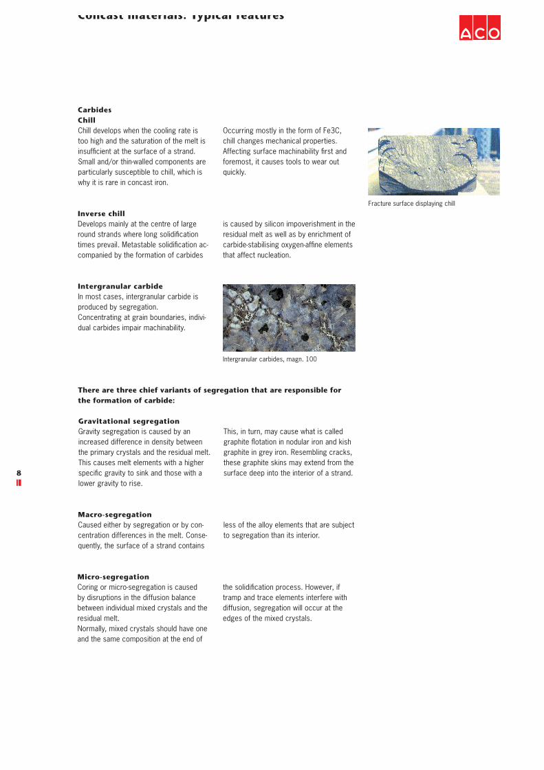
CarbidesChillChill develops when the cooling rate is too high and the saturation of the melt is INSUFlCIENTÏATÏTHEÏSURFACEÏOFÏAÏSTRAND�Small and/or thin-walled components are particularly susceptible to chill, which is why it is rare in concast iron.
Fracture surface displaying chill
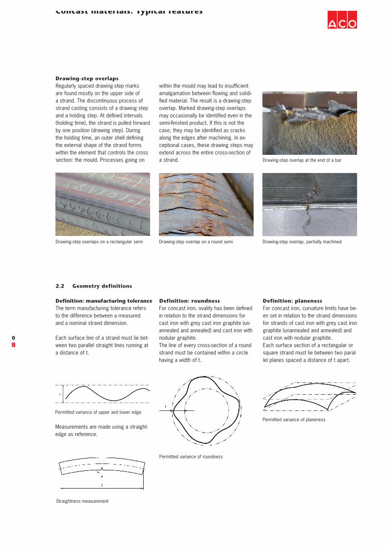
Intergranular carbides, magn. 100
Inverse chillDevelops mainly at the centre of large ROUNDÏSTRANDSÏWHEREÏLONGÏSOLIDIlCATIONÏTIMESÏPREVAIL�Ï-ETASTABLEÏSOLIDIlCATIONÏAC-companied by the formation of carbides
is caused by silicon impoverishment in the residual melt as well as by enrichment of CARBIDE STABILISINGÏOXYGEN AFlNEÏELEMENTSÏthat affect nucleation.
Occurring mostly in the form of Fe3C, chill changes mechanical properties. !FFECTINGÏSURFACEÏMACHINABILITYÏlRSTÏANDÏforemost, it causes tools to wear out quickly.
Intergranular carbideIn most cases, intergranular carbide is produced by segregation. Concentrating at grain boundaries, indivi-dual carbides impair machinability.
There are three chief variants of segregation that are responsible for the formation of carbide:
Gravitational segregationGravity segregation is caused by an increased difference in density between the primary crystals and the residual melt. This causes melt elements with a higher SPECIlCÏGRAVITYÏTOÏSINKÏANDÏTHOSEÏWITHÏAÏlower gravity to rise.
This, in turn, may cause what is called GRAPHITEÏmOTATIONÏINÏNODULARÏIRONÏANDÏKISHÏgraphite in grey iron. Resembling cracks, these graphite skins may extend from the surface deep into the interior of a strand.
Macro-segregationCaused either by segregation or by con-centration differences in the melt. Conse-quently, the surface of a strand contains
less of the alloy elements that are subject to segregation than its interior.
Micro-segregationCoring or micro-segregation is caused by disruptions in the diffusion balance between individual mixed crystals and the residual melt.Normally, mixed crystals should have one and the same composition at the end of
THEÏSOLIDIlCATIONÏPROCESS�Ï(OWEVER�ÏIFÏtramp and trace elements interfere with diffusion, segregation will occur at the edges of the mixed crystals.

19
Concast materials: Typical features
1.3 Inhomogeneities (macroscopic)
InclusionsSince slag inclusions occur most fre-quently within this category, they will be considered in the following.Slag forms during the melting process. It is reduced to a minimum by skimming or slagging. In addition, further measures relating to equipment and process techno-
logy keep slag from the product.Most inclusions are of indeterminate shape and have rough inner walls.Normally, slag is found at the (in the cas-ting position) upper face of a strand be-cause slag is lighter than the melt.
Slag inclusion with a rugged surface Small and big slag inclusions
PoresPores are caused by gas dissolved in the melt. Any gas that does not escape completely during cooling will leave cavi-ties behind that are markedly spherical in shape and have smooth walls. Pores may occur singly or in irregular groups.
This kind of defect occurs only in the upper zone of a strand because gas bubbles are lighter than the melt and drift upward.
Gas bubble with a smooth, shiny surface Gas bubbles of different size
2.1 The production process
Scores
2. Production
Scores develop when a continuous casting mould is damaged. Scores run lengthwise along the strand. This feature does not affect the mechanical properties of a product. To avoid increased tool wear during machining, a tool feed should be set to ensure that tools are evenly loaded and abrasive wear of the castings surface is avoided. Scores on a round strandScore along an edge
20
Concast materials: Typical features
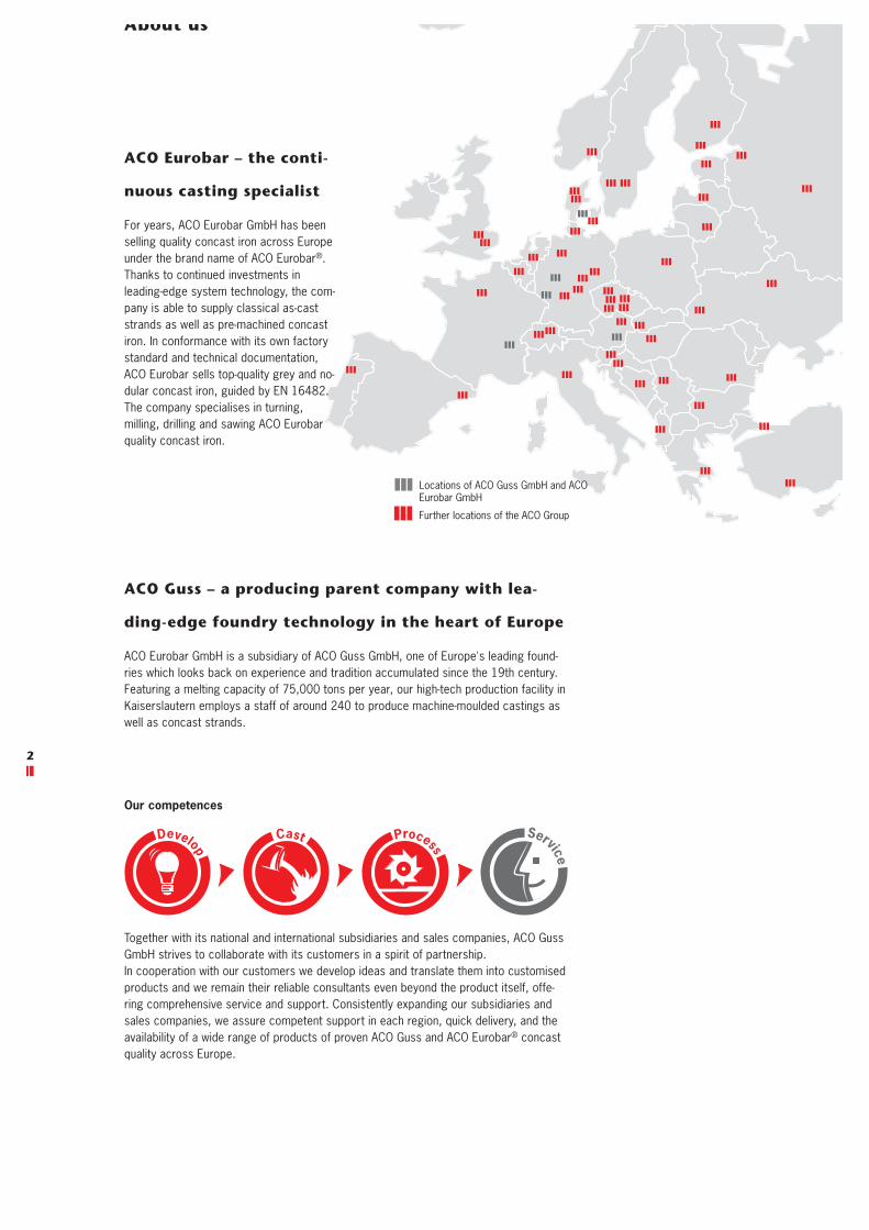
Drawing-step overlapsRegularly spaced drawing-step marks are found mostly on the upper side of a strand. The discontinuous process of strand casting consists of a drawing step ANDÏAÏHOLDINGÏSTEP�Ï!TÏDElNEDÏINTERVALSÏ(holding time), the strand is pulled forward by one position (drawing step). During THEÏHOLDINGÏTIME�ÏANÏOUTERÏSHELLÏDElNINGÏthe external shape of the strand forms within the element that controls the cross section: the mould. Processes going on
WITHINÏTHEÏMOULDÏMAYÏLEADÏTOÏINSUFlCIENTÏAMALGAMATIONÏBETWEENÏmOWINGÏANDÏSOLIDI-lEDÏMATERIAL�Ï4HEÏRESULTÏISÏAÏDRAWING STEPÏoverlap. Marked drawing-step overlaps MAYÏOCCASIONALLYÏBEÏIDENTIlEDÏEVENÏINÏTHEÏSEMI lNISHEDÏPRODUCT�Ï)FÏTHISÏISÏNOTÏTHEÏCASE�ÏTHEYÏMAYÏBEÏIDENTIlEDÏASÏCRACKSÏalong the edges after machining. In ex-ceptional cases, these drawing steps may extend across the entire cross-section of a strand.
Drawing-step overlaps on a rectangular semi Drawing-step overlap on a round semi
Drawing-step overlap at the end of a bar
Drawing-step overlap, partially machined
2.2 Geometry definitions
Definition: manufacturing toleranceThe term manufacturing tolerance refers to the difference between a measured and a nominal strand dimension.
Each surface line of a strand must lie bet-ween two parallel straight lines running at a distance of t.
Permitted variance of upper and lower edge
Straightness measurement
Measurements are made using a straight-edge as reference.
Definition: roundness&ORÏCONCASTÏIRON�ÏOVALITYÏHASÏBEENÏDElNEDÏin relation to the strand dimensions for cast iron with grey cast iron graphite (un-annealed and annealed) and cast iron with nodular graphite.The line of every cross-section of a round strand must be contained within a circle having a width of t.
Permitted variance of roundness
Permitted variance of planeness
Definition: planenessFor concast iron, curvature limits have be-en set in relation to the strand dimensions for strands of cast iron with grey cast iron graphite (unannealed and annealed) and cast iron with nodular graphite.Each surface section of a rectangular or square strand must lie between two paral-lel planes spaced a distance of t apart.

21
Concast materials: Typical features
3.1 Work order
An event that occurs during or before the generation of a work order, preventing the implementation of the customer's
SPECIlCATIONS�Ï3UCHÏEVENTSÏINCLUDEÏCOM-munication errors, omission of necessary data, and deadline scheduling.
3. Non-conformances that may occur during machining
3.2 Semis
Semis: nominal sizeNon-conformance caused by the use of semis having unsuitable initial dimensions.
Semis: material Non-conformance caused by the use of semis consisting of unsuitable material.
3.3 Finished parts: geometry
Dimensional non-conformance(machine-related)Infringement of a dimensional tolerance caused by a machine.
Dimensional non-conformance(operator-related)Infringement of a dimensional tolerance caused by an operator.
Shape non-conformance(machine-related)Infringement of a shape tolerance caused by a machine.
Shape non-conformance(operator-related)Infringement of a shape tolerance caused by an operator.
Position non-conformance(machine-related)Infringement of a position tolerance caused by a machine.
Position non-conformance(operator-related)Infringement of a position tolerance caused by an operator.
Surface structure(machine-related)Infringement of a surface tolerance caused by a machine.
Surface structure(operator-related)Infringement of a surface tolerance caused by an operator.
3.4 Corrosion
Corrosion results from a reaction between a material and its environment which cau-ses measurable changes in the material and may impair the function of a compo-
nent or system. Probably the best-known type of corrosion is rust, i.e. the oxidation of iron.
K. Herfurth, „Gusseisen-Strangguss für eine innovative Teilefertigung,“ Konstruieren und Gießen, Nr. 30, pp. 2-17, 2005.
S. Hasse, Guss- und Gefügefehler, Berlin: Schiele & Schön, 2003.
EN 16482, current version
4. Bibliography
22
Our competences
Together with its national and international subsidiaries and sales companies, ACO Guss GmbH strives to collaborate with its customers in a spirit of partnership.In cooperation with our customers we develop ideas and translate them into customised products and we remain their reliable consultants even beyond the product itself, offe-ring comprehensive service and support. Consistently expanding our subsidiaries and sales companies, we assure competent support in each region, quick delivery, and the availability of a wide range of products of proven ACO Guss and ACO Eurobar® concast quality across Europe.
Service
Process
Develop
Cast
Locations of ACO Guss GmbH and ACO Eurobar GmbH
Further locations of the ACO Group
About us
ACO Eurobar – the conti-
nuous casting specialist
For years, ACO Eurobar GmbH has been selling quality concast iron across Europe under the brand name of ACO Eurobar®. Thanks to continued investments in leading-edge system technology, the com-pany is able to supply classical as-cast strands as well as pre-machined concast iron. In conformance with its own factory standard and technical documentation, ACO Eurobar sells top-quality grey and no-dular concast iron, guided by EN 16482. The company specialises in turning, milling, drilling and sawing ACO Eurobar quality concast iron.
ACO Guss – a producing parent company with lea-
ding-edge foundry technology in the heart of Europe
ACO Eurobar GmbH is a subsidiary of ACO Guss GmbH, one of Europe's leading found-ries which looks back on experience and tradition accumulated since the 19th century. Featuring a melting capacity of 75,000 tons per year, our high-tech production facility in Kaiserslautern employs a staff of around 240 to produce machine-moulded castings as well as concast strands.
23
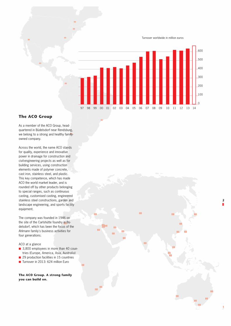
ACO at a glance 3,800 employees in more than 40 coun-tries (Europe, America, Asia, Australia)
29 production facilities in 15 countries Turnover in 2013: 624 million Euro
The ACO Group
As a member of the ACO Group, head-quartered in Büdelsdorf near Rendsburg, we belong to a strong and healthy family-owned company.
Across the world, the name ACO stands for quality, experience and innovative power in drainage for construction and civil-engineering projects as well as for building services, using construction elements made of polymer concrete, cast iron, stainless steel, and plastic. This key competence, which has made ACO the world market leader, and is rounded off by other products belonging to special ranges, such as continuous casting, customised casting, engineered stainless steel constructions, garden and landscape engineering, and sports facility equipment.
The company was founded in 1946 on the site of the Carlshütte foundry in Bü-delsdorf, which has been the focus of the Ahlmann family's business activities for four generations.
The ACO Group. A strong family you can build on.
Turnover worldwide in million euros
07 08 09 10 11 1297 98 99 00 01 02 03 04 05 06
600
500
400
300
200
100
0
13 14

ACO Eurobar GmbH
Hohenecker Straße 567663 KaiserslauternTel. +49 631 2011-0Fax +49 631 2011-459
roba
r/09
/201
4 s
ubje
ct to
cha
nge
No
liabi
lity
for
prin
ting
erro
rs