acetylene & magnegas-2 end-use and safety assessment
TRANSCRIPT
Acetylene & MagneGas-2 End-use and Safety Assessment
A comparative end-use environmental impact and safety analysis of acetylene and Taronis’
MagneGas-2.

1
INDUSTRIAL ASSESSMENT CENTER (IAC)
Arizona State University
CONTRIBUTORS
Ryan Milcarek Principal investigator, Assistant Professor
of Mechanical and Aerospace Engineering
Nicolas Campbell Systems Engineering PhD Student
Brent Skabelund Mechanical Engineering PhD Student
Patrick Phelan Co-investigator, Professor of
Mechanical and Aerospace Engineering
Rene Villalobos Co-investigator, Associate Professor of
Industrial Engineering

2
INDUSTRIAL ASSESSMENT CENTER (IAC)
INDUSTRIAL ASSESSMENT CENTER (IAC)
Table of Contents
Introduction ............................................................................................................................ 3
Acetylene End-use & Safety Assessment .............................................................................. 3
Safety .............................................................................................................................. 3
End-use ........................................................................................................................... 4
Magnegas-2 End-use & Safety Assessment .......................................................................... 5
Safety .............................................................................................................................. 5
End-use ........................................................................................................................... 7
Emissions Analysis ......................................................................................................... 9
Summary .............................................................................................................................. 13
References ............................................................................................................................ 14

3
INDUSTRIAL ASSESSMENT CENTER (IAC)
INDUSTRIAL ASSESSMENT CENTER (IAC)
Introduction
This report includes three main sections on the separate safety and end-use assessments of
acetylene and MagneGas-2 as well as a comparative summary. The safety sections of the report
include information from safety data sheets and literature. The end-use assessments contain the
calculations for the carbon dioxide emissions expected from combustion of the gases.
Acetylene End-use & Safety Assessment
Safety
Information regarding safety in proximity to both the manufacturing and use of acetylene was
collected from safety data sheets as well as literature.
GHS Classification: Flammable Gas – 1
Compressed Gas
Hazards: Extremely Flammable Gas
May form explosive mixtures with air
Contains gas under pressure; may explode if heated
May displace oxygen and cause rapid suffocation
Incompatible Materials: Oxidizers
Conditions to Avoid: Avoid all possible sources of ignition (spark or flame). Do not
pressurize, cut, weld, braze, solder, drill, grind or expose containers
to heat or sources of ignition.
Many of the same threats of the product during production are present during the end-use. There
are dangers for both storing the cylinders as well as combustion of the gas. Acetylene is toxic to
humans when accumulated so leaks in damaged cylinders can be dangerous if stored indoors.
Acute/single exposure to high concentrations of acetylene (>80%) can cause anesthesia,

4
INDUSTRIAL ASSESSMENT CENTER (IAC)
INDUSTRIAL ASSESSMENT CENTER (IAC)
hypertension, and stimulated respiration [1]. According to the same report, there are no studies
done for humans with chronic exposure. Deaths have been reported due to inhalation of acetylene
[2]. Explosive decomposition of acetylene occurs at relatively low temperatures compared to other
gases. It is recommended cylinders are kept below 125 °F. Acetylene cylinders also must be stored
at least 20 feet away from oxygen storage or separated by a wall.
Acetylene has very low stability as the pressure and temperature increase. Compared to other fuels,
stability is particularly low and there are many precautions taken from both the manufacturing and
end-use perspectives.
Figure 1. Energy vs. Stability Pressure for Pure Acetylene [3-5]
Figure 1 shows the decomposition energy with respect to stability pressures of acetylene.
Acetylene is shown to be instable at as low as 3 atm with 55 mJ of energy.
End-use
To assess the impact of the combustion of the fuel, the carbon content of the gaseous fuel must be
analyzed. For the carbon footprint, the following calculations assume complete combustion (i.e.,
all carbon is fully oxidized to carbon dioxide and all hydrogen to water vapor). As shown later in
the emissions analysis, some of the carbon and hydrogen are present as other trace species (e.g.,

5
INDUSTRIAL ASSESSMENT CENTER (IAC)
INDUSTRIAL ASSESSMENT CENTER (IAC)
CO, C2H4), the concentration of which varies with temperature of the reactions. With the complete
combustion assumption for oxyacetylene combustion, the chemical balance is:
C2H2(g) + 2.5O2(g) ⟶ 2CO2(g) + H2O(g)
Carbon, hydrogen, and oxygen have molar masses of 12.01𝑔
𝑚𝑜𝑙 , 1.00
𝑔
𝑚𝑜𝑙, and 16.0
𝑔
𝑚𝑜𝑙,
respectively. The amount of CO2 produced on a weight basis can be calculated:
2 𝑚𝑜𝑙 𝐶𝑂2 × 44.01
𝑔𝑚𝑜𝑙 𝐶𝑂2
1 𝑚𝑜𝑙 𝐶2𝐻2 × 26.02𝑔
𝑚𝑜𝑙 𝐶2𝐻2
= 3.38𝑘𝑔 𝐶𝑂2
𝑘𝑔 𝐶2𝐻2
Using this and the density of the gas the expected carbon footprint can be calculated:
𝐶𝐹𝑒𝑛𝑑−𝑢𝑠𝑒 = 3.38𝑘𝑔 𝐶𝑂2
𝑘𝑔 𝐶2𝐻2× 0.033
𝑘𝑔 𝐶2𝐻2
𝑐𝑢. 𝑓𝑡. 𝐶2𝐻2= 0.112
𝑘𝑔 𝐶𝑂2
𝑐𝑢. 𝑓𝑡. 𝐶2𝐻2
Magnegas-2 End-use & Safety Assessment
Safety
Safety related information is primarily captured by the available safety data sheet (SDS). There is
not significant information in publications on MagneGas to be included in this section.
GHS Classification: Flammable Gas – 1
Compressed Gas
Acute Toxicity, Inhalation – 4
Skin Corrosion / Irritation – 3
Serious Eye Damage / Eye Irritation – 2B
Hazards: Extremely Flammable Gas
Contains gas under pressure; may explode if heated
Causes mild skin irritation
Causes eye irritation
Harmful if inhaled
May cause asphyxia
May cause frostbite upon sudden release of compressed gas
6
INDUSTRIAL ASSESSMENT CENTER (IAC)
INDUSTRIAL ASSESSMENT CENTER (IAC)
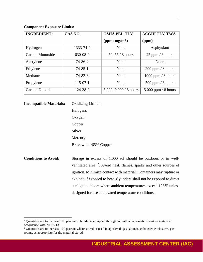
Component Exposure Limits:
INGREDIENT: CAS NO. OSHA PEL-TLV
(ppm; mg/m3)
ACGIH TLV-TWA
(ppm)
Hydrogen 1333-74-0 None Asphyxiant
Carbon Monoxide 630-08-0 50; 55 / 8 hours 25 ppm / 8 hours
Acetylene 74-86-2 None None
Ethylene 74-85-1 None 200 ppm / 8 hours
Methane 74-82-8 None 1000 ppm / 8 hours
Propylene 115-07-1 None 500 ppm / 8 hours
Carbon Dioxide 124-38-9 5,000; 9,000 / 8 hours 5,000 ppm / 8 hours
Incompatible Materials: Oxidizing Lithium
Halogens
Oxygen
Copper
Silver
Mercury
Brass with >65% Copper
Conditions to Avoid: Storage in excess of 1,000 scf should be outdoors or in well-
ventilated area1,2. Avoid heat, flames, sparks and other sources of
ignition. Minimize contact with material. Containers may rupture or
explode if exposed to heat. Cylinders shall not be exposed to direct
sunlight outdoors where ambient temperatures exceed 125°F unless
designed for use at elevated temperature conditions.
1 Quantities are to increase 100 percent in buildings equipped throughout with an automatic sprinkler system in
accordance with NFPA 13. 2 Quantities are to increase 100 percent where stored or used in approved, gas cabinets, exhausted enclosures, gas
rooms, as appropriate for the material stored.

7
INDUSTRIAL ASSESSMENT CENTER (IAC)
INDUSTRIAL ASSESSMENT CENTER (IAC)
Analysis of Magnegas-2 has been performed by both WHA International as well as the NASA
White Sands Test Facility. These analyses included stability and it was found that MagneGas-2
and MagneGas-Butanol are very stable at higher temperatures and pressures than acetylene.
Figure 2. Acetylene/MagneGas-Butanol Comparison Regression Analysis Results with Indicated
Ignition Energy [4,5]
Figure 2 shows the decomposition energy with respect to stability pressures of MagneGas-2 (MG2)
and MagneGas-Butanol (MG2B), similar to Figure 1 for acetylene. RM01 is the 1% predicted
ignition probability and RU01 is the single-tail 95% confidence interval at that probability.
End-use
The components of MagneGas-2 were measured and the average values for each component are
shown in Table 1. It should be noted that there are more components that exist other than those
listed in Table 1, however, those listed make up 99.38% of the total.

8
INDUSTRIAL ASSESSMENT CENTER (IAC)
INDUSTRIAL ASSESSMENT CENTER (IAC)
Table 1. MagneGas-2 Composition
Chemical Composition Average %(Vol/Vol)
H2 51.97
CO 24.56
C2H2 11.42
CH4 6.65
C2H4 4.78
To assess the impact of the combustion of MagneGas-2, the values in Table 1 will be used to
calculate the CO2 emissions. For the carbon footprint, the following calculations assume complete
combustion (i.e., all carbon is fully oxidized to carbon dioxide and all hydrogen to water vapor).
As shown later in the emissions analysis, some of the carbon and hydrogen are present as other
trace species (e.g., CO, C2H4), the concentration of which varies with temperature of the reactions.
With the complete combustion assumption for oxy-MagneGas-2 combustion, the chemical balance
is:
0.5197𝐻2 + 0.2456𝐶𝑂 + 0.1142𝐶2𝐻2 + 0.0665𝐶𝐻4 + 0.0478𝐶2𝐻4 + 0.9446𝑂2
⟶ 0.8625𝐻2𝑂 + 0.6361𝐶𝑂2
𝐶𝐸𝐶𝑂2 =0.6361 𝑚𝑜𝑙 𝐶𝑂2
0.9938 𝑚𝑜𝑙 𝑓𝑢𝑒𝑙= 0.6401
𝑚𝑜𝑙 𝐶𝑂2
𝑚𝑜𝑙 𝑓𝑢𝑒𝑙
Converting this into a form that is usable for the carbon footprint, CFend-use. First the molar mass
of the fuel is calculated:
=1
0.9938[[0.5197(2) + 0.1142(2) + 0.0665(4) + 0.0478(4)]
𝑚𝑜𝑙 𝐻
𝑚𝑜𝑙 𝑓𝑢𝑒𝑙× 1
𝑔
𝑚𝑜𝑙 𝐻
+ [0.2456(1) + 0.1142(2) + 0.0665(1) + 0.0478(2)]𝑚𝑜𝑙 𝐶
𝑚𝑜𝑙 𝑓𝑢𝑒𝑙× 12.01
𝑔
𝑚𝑜𝑙 𝐶
+[0.2456(1)]𝑚𝑜𝑙 𝑂
𝑚𝑜𝑙 𝑓𝑢𝑒𝑙× 16
𝑔
𝑚𝑜𝑙 𝑂]] = 13.38
𝑔 𝑓𝑢𝑒𝑙
𝑚𝑜𝑙 𝑓𝑢𝑒𝑙
𝐶𝐹𝑒𝑛𝑑−𝑢𝑠𝑒 = 0.6401
𝑚𝑜𝑙 𝐶𝑂2
𝑚𝑜𝑙 𝑓𝑢𝑒𝑙× (12 + 32)
𝑔 𝐶𝑂2
𝑚𝑜𝑙 𝐶𝑂2
13.38𝑔 𝑓𝑢𝑒𝑙
𝑚𝑜𝑙 𝑓𝑢𝑒𝑙
= 2.105𝑘𝑔 𝐶𝑂2
𝑘𝑔 𝑓𝑢𝑒𝑙
Then we find the density of the fuel to convert it into a cubic feet basis:

9
INDUSTRIAL ASSESSMENT CENTER (IAC)
INDUSTRIAL ASSESSMENT CENTER (IAC)
𝜌𝑓𝑢𝑒𝑙 = 13.38𝑔 𝑓𝑢𝑒𝑙
𝑚𝑜𝑙 𝑓𝑢𝑒𝑙× 1.195
𝑚𝑜𝑙 𝑓𝑢𝑒𝑙
𝑐𝑢. 𝑓𝑡. 𝑓𝑢𝑒𝑙×
1 𝑘𝑔 𝑓𝑢𝑒𝑙
1000 𝑔 𝑓𝑢𝑒𝑙= 0.016
𝑘𝑔 𝑓𝑢𝑒𝑙
𝑐𝑢. 𝑓𝑡. 𝑓𝑢𝑒𝑙
Finally, we can calculate the emissions on a cubic feet basis:
𝐶𝐹𝑒𝑛𝑑−𝑢𝑠𝑒 = 2.105𝑘𝑔 𝐶𝑂2
𝑘𝑔 𝑓𝑢𝑒𝑙× 0.016
𝑘𝑔 𝑓𝑢𝑒𝑙
𝑐𝑢. 𝑓𝑡. 𝑓𝑢𝑒𝑙= 0.034
𝑘𝑔 𝐶𝑂2
𝑐𝑢. 𝑓𝑡. 𝑀𝐺
Emissions Analysis
The MagneGas-2 fuel was oxidized inside a 6-inch diameter stainless steel combustor and the
combustion exhaust was characterized with a gas chromatograph. The combustor was lined with
a ceramic thermal insulation to minimize the heat loss to the surroundings. This resulted in higher
flame and exhaust temperatures. The oxidation was then repeated with the ceramic insulation
removed. A schematic of the experimental setup is shown in Fig. 3 below.
Figure 3. Schematic of the Combustion Characterization Chamber
The gas composition of the MagneGas-2 utilized in the experiment was analyzed by the gas
chromatograph and tabulated in Table 2 below. It is important to note that the composition is

10
INDUSTRIAL ASSESSMENT CENTER (IAC)
INDUSTRIAL ASSESSMENT CENTER (IAC)
slightly different than stated in Table 1 above. The operating equivalence ratio, ϕ, was 0.572 with
pure oxygen as the oxidant. The flow rates utilized in the experiment are listed in Table 3. The
results of the dry exhaust combustion analysis are shown in Table 4 below.
Table 2. MagneGas-2 Composition Utilized in Experiment
Gas Species Gas Concentration Mole %
Methane (CH4) 6.25
Ethylene (C2H4) 3.86
Acetylene (C2H2) 11.56
Carbon Monoxide (CO) 30.08
Hydrogen (H2) 48.25
Total 100.00
Table 3. Equivalence Ratio and MagneGas-2/Oxygen Flow Rates
Equivalence Ratio MagneGas-2 (SLM) Oxygen (O2) (SLM)
0.572 3.151 5.078

11
INDUSTRIAL ASSESSMENT CENTER (IAC)
INDUSTRIAL ASSESSMENT CENTER (IAC)
Table 4. Dry Exhaust Composition of the MagneGas-2 Oxidation
Exhaust Species Measured Gas Concentration Mole %
(Insulated)
Gas Concentration Mole %
(Non-Insulated)
Methane (CH4) 0.0004* 0.0047
Ethane (C2H6) 0 0.00003*
Ethylene (C2H4) 0.0001* 0.0012*
Acetylene (C2H2) 0.0003* 0.0026
Propane (C3H8) 0 0
Propylene (C3H6) 0.0001* 0.0004*
Cyclopropane (C3H6) 0 0
n-Butane (C4H10) 0 0
iso-Butane (C4H10) 0 0
iso-Butylene (C4H8) 0 0
Trans-2-Butene (C4H8) 0 0
Cis-2-Butene (C4H8) 0 0
1,3-Butadiene (C4H6) 0 0
n-Pentane (C5H12) 0 0
iso-Pentane (C5H12) 0 0
C6+** 0 0
Carbon Monoxide (CO) 0.0080 0.3473
Oxygen (O2) 23.9376 21.3749
* - Above/below calibrated range of gas chromatograph. The lower calibrated bound of the gas
chromatograph for hydrocarbons is 0.0015% (15 ppm). Interpolation was used to get results.
** - Hydrocarbons that are C6Hx and greater.

12
INDUSTRIAL ASSESSMENT CENTER (IAC)
INDUSTRIAL ASSESSMENT CENTER (IAC)
With the equivalence ratio and the measured values of CH4, C2H4, C2H2, C3H6, and CO, the
following reaction balance reaction occurs. The combustion emissions of CO2 are:
0.572(48.25 𝐻2 + 30.08 𝐶𝑂 + 11.56 𝐶2𝐻2 + 6.25 𝐶𝐻4 + 3.86 𝐶2𝐻4) + 92.145 𝑂2
⟶ 0.0004 𝐶𝐻4 + 0.0001 𝐶2𝐻4 + 0.0003 𝐶2𝐻2 + 0.0001 𝐶3𝐻6 + 0.008 𝐶𝑂
+ 38.412 𝐶𝑂2 + 45.775 𝐻2𝑂 + 39.444 𝑂2
To calculate an equivalent carbon footprint of the other emissions, assuming complete
combustion.
0.0004 𝐶𝐻4 + 0.0001 𝐶2𝐻4 + 0.0003 𝐶2𝐻2 + 0.0001 𝐶3𝐻6 + 0.008 𝐶𝑂 + 0.0095 𝑂2
⟶ 0.0095 𝐶𝑂2
𝐶𝐸𝐶𝑂2 =38.423 𝑚𝑜𝑙 𝐶𝑂2
57.2 𝑚𝑜𝑙 𝑓𝑢𝑒𝑙= 0.6717
𝑚𝑜𝑙 𝐶𝑂2
𝑚𝑜𝑙 𝑓𝑢𝑒𝑙
Converting this into a form that is usable for the carbon footprint, CFend-use. First the molar mass
of the fuel is calculated:
=1
100[[48.25(2) + 11.56(2) + 6.25(4) + 3.86(4)]
𝑚𝑜𝑙 𝐻
𝑚𝑜𝑙 𝑓𝑢𝑒𝑙× 1.008
𝑔
𝑚𝑜𝑙 𝐻
+ [30.08(1) + 11.56(2) + 6.25(1) + 3.86(2)]𝑚𝑜𝑙 𝐶
𝑚𝑜𝑙 𝑓𝑢𝑒𝑙× 12.01
𝑔
𝑚𝑜𝑙 𝐶
+[30.08(1)]𝑚𝑜𝑙 𝑂
𝑚𝑜𝑙 𝑓𝑢𝑒𝑙× 16
𝑔
𝑚𝑜𝑙 𝑂]] = 14.493
𝑔 𝑓𝑢𝑒𝑙
𝑚𝑜𝑙 𝑓𝑢𝑒𝑙
𝐶𝐹𝑒𝑛𝑑−𝑢𝑠𝑒 = 0.6717
𝑚𝑜𝑙 𝐶𝑂2
𝑚𝑜𝑙 𝑓𝑢𝑒𝑙× (12.01 + 32)
𝑔 𝐶𝑂2
𝑚𝑜𝑙 𝐶𝑂2
14.493𝑔 𝑓𝑢𝑒𝑙
𝑚𝑜𝑙 𝑓𝑢𝑒𝑙
= 2.0397𝑘𝑔 𝐶𝑂2
𝑘𝑔 𝑓𝑢𝑒𝑙
Then we find the density of the fuel to convert it into a cubic feet basis:
𝜌𝑓𝑢𝑒𝑙 = 14.493𝑔 𝑓𝑢𝑒𝑙
𝑚𝑜𝑙 𝑓𝑢𝑒𝑙× 1.1698
𝑚𝑜𝑙 𝑓𝑢𝑒𝑙
𝑐𝑢. 𝑓𝑡. 𝑓𝑢𝑒𝑙×
1 𝑘𝑔 𝑓𝑢𝑒𝑙
1000 𝑔 𝑓𝑢𝑒𝑙= 0.0170
𝑘𝑔 𝑓𝑢𝑒𝑙
𝑐𝑢. 𝑓𝑡. 𝑓𝑢𝑒𝑙
Finally, we can calculate the emissions on a cubic feet basis:
𝐶𝐹𝑒𝑛𝑑−𝑢𝑠𝑒 = 2.0397𝑘𝑔 𝐶𝑂2
𝑘𝑔 𝑓𝑢𝑒𝑙× 0.0170
𝑘𝑔 𝑓𝑢𝑒𝑙
𝑐𝑢. 𝑓𝑡. 𝑓𝑢𝑒𝑙= 0.035
𝑘𝑔 𝐶𝑂2
𝑐𝑢. 𝑓𝑡. 𝑀𝐺

13
INDUSTRIAL ASSESSMENT CENTER (IAC)
INDUSTRIAL ASSESSMENT CENTER (IAC)
Summary
Comparing acetylene and MagneGas-2, it has been revealed that MagneGas-2 is significantly more
stable at higher pressures and temperatures as well as emits less carbon dioxide upon combustion.
A comparative stability graph is shown in Figure 3.
Figure 4. Decomposition Energy vs. Pressure for MagneGas-2 and Pure Acetylene [4,5]
The stability of the gas is indicative of its safety for storage and use. MagneGas-2 has many of the
same physical dangers associated in storage and use as acetylene, however, at much more extreme
conditions which are unlikely to occur. Acetylene explosions are well documented, happening in
both transportation as well as in storage.
The combustion of MagneGas-2 has been shown to have significantly less environmental
impactful. It contributes 70% or 0.078𝑘𝑔𝐶𝑂2
𝑐𝑢.𝑓𝑡 less carbon dioxide than acetylene on a volume basis.
A summary table of the stability and carbon emissions is shown in the following table. At the time
of this report, WHA International was performing Gas Stability tests with the MagneGas produced
from ethanol feedstock, the same gas that this analysis and tests were performed with. Preliminary
testing results indicate that Ignition Energy at 100 atm is also >1,000 mJ.

14
INDUSTRIAL ASSESSMENT CENTER (IAC)
INDUSTRIAL ASSESSMENT CENTER (IAC)
Table 5. Summary comparison between oxyacetylene and oxy-MagneGas-2
Oxyacetylene
(Calculated)
Oxy-MagneGas-2
(Calculated)
Oxy-MagneGas-2
(Experimental)
Carbon Footprint 0.112𝑘𝑔 𝐶𝑂2
𝑐𝑢. 𝑓𝑡. 𝐶2𝐻2 0.034
𝑘𝑔 𝐶𝑂2
𝑐𝑢. 𝑓𝑡. 𝑀𝐺 0.035
𝑘𝑔 𝐶𝑂2
𝑐𝑢. 𝑓𝑡. 𝑀𝐺
Safety - Ignition
energy at 100 atm < 5 mJ NA >1000 mJ
References
[1] Public Health England Toxicology Department. Acetylene Toxicological Overview. Version
1. 2009.
[2] Williams, N. R. and Whittington, R. M. (2001). Death due to inhalation of industrial
acetylene. J Toxicol Clin Toxicol 39, 69-71.
[3] Miller, S. (1965). Acetylene: Its Properties, Manufacture and Uses. New York: Academic
Press.
[4] Whitehead, J. Linley, N. and Newton, B. (2017). Pressure and Energy Stability Measurements
of MagneGas 2TM, WHA International, 1-8.
[5] Whitehead, J., Linley, N., and Newton, B. (2017). Pressure and Energy Stability Comparisons
between MagneGas 2TM and MagneGas 2BTM, WHA International, 1-4.