accident investigation report commercial barge … · possible external dynamic factors affecting...
TRANSCRIPT

Accident ReportDouble Fatality
Rakanui & Mac III19 August 2005
Class A

Maritime New Zealand Investigation Report 2
Figure1 Dumb barge Mac III & tug boat Rakanui. Tiro l was not involved in the accident. Photograph taken on the morning of the accident.
Mac III Rakanui

Maritime New Zealand Investigation Report 3
CONTENTS SECTION PAGE
NUMBER Contents ……………………………………………………………………………………………………. 3
Glossary …………………………………………………………………………………………………….. 5
Vessel Details – Rakanui …………………………………………………………………………………. 7
Vessel Details – Mac III …………………………………………………………………………….…….. 8
Vehicle Details ……………………………………………………………………………………………... 9
Narrative ……………………………………………………………………………………………………. Particulars of Vessel, Ownership, Certification & Crew ………………………………………………. Particulars of Tug Boat Rakanui …………………………………………………………………….. Particulars of Barge Mac III ………………………………………………………………………….. Ownership ……………………………………………………………………………………………... Certification ……………………………………………………………………………………………. Rakanui ……………………………………………………………………………………….…….. Mac III ………………………………………………………………………………………………. Crew & Certification …………………………………………………………………………….…….. Skipper ………………………………………………………………………………………………. Deckhand …………………………………………………………………………………………… Particulars of Trucks, Ownership & Certification …………………………………………………… Cement Trucks ……………………………………………………………………………….…….. Ownership …………………………………………………………………………………….…….. Details of the Deceased Drivers …………………………………………………………….……..
10 10 10 10 10 10 10 10 11 11 11 11 11 12 12
The Accident ……………………………………………………………………………………………….. Rakanui & Mac III …………………………………………………………………………………….. Discussion Regarding Loading Sequence ………………………………………………………….. Loading the Barge ……………………………………………………………………………………..
13 16 17 19
Comment & Analysis ……………………………………………………………………………….…….. Evidence ………………………………………………………………………………………………….. Analysis …………………………………………………………………………………………….…….. History …………………………………………………………………………………………………. Legislation ……………………………………………………………………………………….…….. Maritime Rule Part 40C ……………………………………………………………………….. Maritime Rule Part 47 …………………………………………………………………………. Other Maritime Rules ……………………………………………………………………………. Stability Criteria Developed by Ministry of Transport (MOT86) ……………………………… Analysis of the Loading Sequence Prior to the Accident & its Effect on Mac III’s stability……. Summary of Mac III’s Statical Stability During the Course of Loading…………………………… Analysis of the Proposed Loading Condition on Mac III ………………………………………….. The Load Two Days Prior to the Accident ………………………………………………………….. The Deck of Mac III & the Coefficient of Friction (conditions underfoot) ………………………… The Stability of the Cement Trucks ………………………………………………………………….. Maritime Qualification & Training …………………………………………………………………….. Stability Syllabus for CLM/ILM ………………………………………………………………………. Firth Driver Training …………………………………………………………………………………… The Condition & Construction of the Loading Ramp ……………………………………………… Summary of SGS-M&I Report on the Loading Ramp’s Condition ……………………………….. Firth Internal Investigation ……………………………………………………………………………. Possible External Dynamic Factors Affecting Mac III ……………………………………………… Santa Regina ………………………………………………………………………………………. Contractual Relationships ……………………………………………………………………………. McManaway Tug & Barge Ltd and Crafar Crouch ……………………………………………… Crafar Crouch and Firth ……………………………………………………………………………….
22 22 22 22 23 23 24 25 26 26 28 29 30 31 32 33 33 35 35 36 37 38 38 39 39 39

Maritime New Zealand Investigation Report 4
Maritime Rule Part 24B – Carriage of Cargoes – Stowage and Securing ……………….…….. Incremental Drift ………………………………………………………………………………………. Human-Human Coordination Breakdowns …………………………………………………………. Health & Safety in Employment Act 1992 …………………………………………………………... Duties under Part 2 of the HSEA ………………………………………………………….…….. Breaches of Duties under Part 2 of the HSEA ………………………………………………….
40 40 41 42 42 43
Conclusions ………………………………………………………………………………………….…….. Latent Failures ……………………………………………………………………………………………. Active Failures …………………………………………………………………………………………….
46 46 47
Safety Recommendations ……………………………………………………………………………….. 48
Figures & Appendices Figure 1 – Photograph of Mac III & Rakanui ……………………………………………………………. Diagram 1 …………………………………………………………………………………………………... Figure 2 – Extract of Chart NZ 6153, Queen Charlotte Sound ………………………………………... Figure 3 – Extract of Chart NZ 6154 Tory Channel Entrance & Picton Harbour …………………….. Figure 4 – Photograph of Mac III with loading ramp …………………………………………………… Figure 5 – Photograph showing proposed loading plan on Mac III …………………………………... Figure 6 – Photograph showing steel girders underneath the ramp ………………………………….. Figure 7 – Photograph showing damage to Rakanui ………………………………………………….. Figure 8 – Photograph of deck of Mac III ……………………………………………………………….. Figure 9 – Photograph showing damage to ramp of Mac III ………………………………………….. Figure 10 – Photograph showing position of the 4th rear axle and damage to ramp ………………... Appendix 1 – Mac III Dumb Barge Inclining Experiment & Stability Report …………………………. Loadcase 1 ……………………………………………………………………………………………. Loadcase 2 ……………………………………………………………………………………………. Loadcase 3 ……………………………………………………………………………………………. Loadcase 4 ……………………………………………………………………………………………. Loadcase 5 ……………………………………………………………………………………………. Loadcase 6(i) ………………………………………………………………………………………….. Loadcase 6(ii) ………………………………………………………………………………………….. Loadcase 6(iii) …………………………………………………………………………………………. Loadcase 7(i) ………………………………………………………………………………………….. Loadcase 7(ii) …………………………………………………………………………………………. Appendix 2 – Mac III Dumb Barge Loading Ramp Condition Report ………………………………… Appendix 3 – Commercial Launchmaster Certificate Syllabus ………………………………………… Appendix 4 – Graph TCG vs List (deg) ………………………………………………………………….. Appendix 5 – Maritime Rule Part 40C – Section 4 Barges ……………………………………………. Appendix 6 – Maritime Rule Part 47 – Load Lines – Section 2 ………………………………………..
2 6 14 15 17 18 19 21 32 36 36 49 51 54 58 65 69 73 75 77 83 87 92 95 100 101 110

Maritime New Zealand Investigation Report 5
GLOSSARY TERM DESCRIPTION Aft: Behind the ship; near or around the stern or towards the stern of the ship.
Opposite of fore.
Amidships: In or near the centre of a ship, whether longitudinally or transversely.
Barge: A large boat with a flat bottom used for carrying of goods on rivers, canals, shallow waters etc.
Block Coefficient: The ratio of the underwater volume of a ship to the volume of a rectangular block having the length, breadth and draught of the ship CB = immersed volume / L x B x H.
Bulwark: Shell plating about one metre in height built around the outboard edge of upper deck from forecastle to poop to protect men and cargo against rough seas.
Buoyancy: The upthrust given by the water which keeps a ship afloat; the difference between the vertical component of the hydrostatic pressure acting on the ship’s hull and the weight of the ship.
Cargo: Goods carried on a ship.
Cargo Plan: A plan which marks and indicates the locations of various cargoes stowed on board; the plan may be a simple outline of the ship’s cargo spaces.
Centre of Flotation: The geometrical centre of the waterplane area around which a ship may be assumed to trim.
Centre of Buoyancy: The geometrical centre of the volume of water displaced by a floating ship, about which the total moments of the displaced volume will be zero.
Centre of Gravity: The geometrical centre of a ship through which the whole weight of the ship may be assumed to act. Represented by letter ‘G’ in this report.
Centreline: The middle line of a ship running in the fore and aft direction.
Chain: Connected metal rings or links used for holding anchors, fastening timber cargoes etc.
Draught: The vertical distance measured from the lowest point of a ship’s hull to the waterline at which the vessel floats.
Dynamic Stability: Describes the ability of a floating body to remain upright when subjected to external disturbance such as wind or wave motions.
Dynamical Stability: Of a ship at a given angle of heel, it is the work done to heel the ship to that angle; it is proportional to the area under the statical stability curve up to that angle.
GM: This is the distance between the centre of gravity and the metacentre.
Heave: 1. Describes the vertical, up and down motion of a ship; one of the six principal motions of a ship in waves;
2. To lift something. Compare pitch, roll, surge, sway, yaw.
Heel: 1. Of a ship, to list or incline to one side;
2. Transverse inclination due to wind pressure, weight shift or rudder action;
3. The corner of an angle, bulb angle or channel, commonly used in reference to the moulded line.
Intact Stability: Values of transverse and longitudinal metacentric heights (in metres) – the measures of the (upright) ship’s ability to resist overturning.
Keel: A line of plates running along the centreline of a ship’s bottom forming the backbone of the ships frames; usually thicker than other adjacent plates.
KG: The vertical height of the centre of gravity above the keel.
List: To heel or lean over to one side; a transverse inclination of a ship.

Maritime New Zealand Investigation Report 6
Load Lines: The lines which are marked and painted amidships on each side of a ship to
indicate the maximum permissible draughts of loading adjusted for various seasons and zones; also known as Plimsoll marks.
Main Deck: The continuous deck that extends between the forward and after end of a ship.
Marine Surveyor: One who inspects ships to assess, monitor and report on the condition of the ship, her machinery and cargo; depending on the type of survey carried out. The evaluation requirements may be statutory, class, marine insurance etc.
Metacentre: A theoretical point when dealing with ship stability for small angles of inclination from the upright position; consider a floating ship heeling to a small angle, the centre of buoyancy B will shift towards the newly immersed side to B1, and the vertical line of force through this new centre of buoyancy B1 will intersect the original line of force when the ship is upright at M, known as the metacentre (See Diagram 1 below).
Metacentric Height: The distance from the centre of gravity of a ship to the metacentre; it’s considered positive if the metacentre lies above centre of gravity.
Midship: In or near the middle of a ship; same as amidships.
Moment of Statical Stability:
This is the moment at which the barge will try to return to the upright position when the barge is heeled.
Neap Tide: A tide, which twice in a lunar month, rises and falls the least from mean sea level.
Port side: Left side of a ship when looking forwards towards the bow; sometimes written as port side.
Righting Lever: Perpendicular distance between centre of gravity, G and the imaginary vertical line passing through the centre of buoyancy, B; it will cause the floating body to right itself until both centres, G and B are in line, i.e., the lever becomes zero; commonly abbreviated as GZ.
Starboard: The right side of a ship when facing forwards towards the bow. Opposite of port.
Stern: The after end of a ship; based on the different cross sectional shapes, a ship may be described as having a counter stern, full cruiser stern, transom stern etc., opposite of bow.
Tender: Occurs when the GM and the righting moments at small angles of heel are comparatively small. A ship will be easier to incline and the time period for it to return to the initial position will be longer. In this condition a ship is said to be ‘tender’.
Tugboat: A small boat designed for towing vessels such as a barge; has great manoeuvrability and engine power; also known simply as a tug.
Waterline: The line at a ship’s side formed by the surface of the water at a specific draught.
Waterplane: Horizontal section of a ship’s hull at a particular depth.
Waterplane Coefficient: The ratio of the waterplane area to the rectangular area given by the product of ship’s length and breadth.
Diagram 1
Metacentre:

Maritime New Zealand Investigation Report 7
REPORT NO.: 05 3885
VESSEL NAME: RAKANUI
Ship Type: Tug Boat
Certified Operating Limit:
Inshore Limits – Nelson/Marlborough
Port of Registry:
Dunedin
Flag:
New Zealand
MSA No.:
152195
Built: 1926 by Bailey & Lowe, Auckland
Construction Material: Wooden
Length Overall (m): 15.59
Maximum Breadth (m): 3.84
Gross Tonnage:
21.62
Net Tonnage:
4.15
Registered Owner:
McManaway Tug and Barge Ltd
Ship Operator/Manager:
McManaway Tug and Barge Ltd
SSM Company:
SGS-M&I
Sunrise Sunrise at Picton on 19 August 2005 was at 0709.30 hours.
Tides Tides on 19 August 2005 were: Low water 0137 hours at a height of 0.2 metres above chart datum High water 0850 hours at a height of 1.2 metres above chart datum It was a neap tide. The height of tide above chart datum at 0615 hours was 0.842 metres.

Maritime New Zealand Investigation Report 8
VESSEL NAME: MAC III
Ship Type: Dumb barge
Flag:
New Zealand
Built: Mid 1960’s by Despatch Engineering, Greymouth
Construction Material: Steel
Length Overall (m): 22
Maximum Breadth (m): 5.8
Calculated Displacement:
38.82 tonnes
Registered Owner:
McManaway Tug and Barge Ltd
Ship Operator/Manager:
McManaway Tug and Barge Ltd

Maritime New Zealand Investigation Report 9
VEHICLE DETAILS
Vehicle 1 Vehicle 2
Type: Isuzu Hino
Model:
FVZ1400 FVO
FM
VIN No.:
JALFVZ23ST3000003 JHDFM1JRPXXX10171
Year: 1996 2004
Colour: White/Yellow White/Yellow
Vehicle Type: 6 x 4 8 x 4
TARE Weight: 9 660 kgs 11 040 kgs
Manufacturers Gross Laden Weight:
22 500 kgs
28 600 kgs

Maritime New Zealand Investigation Report 10
NARRATIVE
Particulars of Vessel, Ownership, Certification & Crew
Particulars of Tug Boat Rakanui Rakanui was built in1926 by Bailey & Lowe of Auckland. She is of wooden construction and powered by two General Motors diesel engines developing 252Kw. She is propelled by two shafts and steered by two semi-balanced rudders (See Figure 1 - Photograph of Rakanui).
Particulars of Barge Mac III Mac III was built in Greymouth by Despatch Engineering in the mid 1960’s. The barge was originally built as a motorised bottom dump barge and plied the Grey River transporting river rock. In the mid 1990’s, McManaway Tug and Barge Limited (“McManaway”) the current owners, purchased the barge. After purchase, McManaway contracted Grey Brother Engineering in Greymouth to modify the barge. The hopper doors were removed along with the propulsion motor and the openings in the hull were blanked with steel plate. On completion of the modifications, the barge was towed from Greymouth to Picton where, on arrival, the barge was fitted with a loading ramp (See Figure 1 - Photograph of Mac III). McManaway operate two other barges, Mac II and Waimarie. Mac II is identical to the Mac III, except that it has a deck crane.
Ownership Rakanui and Mac III are both owned by McManaway. The Managing Director of McManaway is a holder of a Commercial Launchmaster’s Certificate (CLM) which was issued in April 1989. McManaway has extensive experience of barge operation and the carriage of cargoes, having operated since the early 1980’s.
Certification
Rakanui All the vessel’s certification at the time of the accident was valid and compliant with the requirements of the Maritime Transport Act 1994. Rakanui was used to tow barges such as Mac III. During the course of the towing operation, persons/passengers travelled on board Rakanui.
Mac III Under New Zealand’s current maritime legislation, Mac III was not required to hold any certification, be subject to any surveys or to be registered as a commercial vessel. Mac III’s overall length is 22 metres. The barge was not certified to carry persons/passengers on board during the course of a voyage and the Managing Director of McManaway had instructed the skippers of the tug not to carry people on the barge during a voyage. Obviously, however, persons would be on the barge during loading or unloading operations while trucks were arriving on and off. There is evidence of truck drivers breaching this standing order on occasions and remaining in their truck cabs for part of the voyage.

Maritime New Zealand Investigation Report 11
McManaway stated that the barge did not proceed beyond Inshore limits – Nelson/Marlborough. Mac III, being a New Zealand barge under 24 metres in length, that did not carry persons on board during the course of a voyage, was not required to comply with Part 40C.69, Section 4 – Barges. Under Maritime Rule 21.9(1)(d) – Safe Ship Management Systems, Mac III was not required to be in Safe Ship Management (SSM)1 because it did not carry any persons on board during the course of a voyage2. Mac III was not required to be registered under New Zealand’s Ship Registration Act 1992. Under Maritime Rule Part 47.6 and 47.69, Mac III was not required to comply with the load line rules, because the barge was under 24 metres in length and did not carry passengers on board during the course of a voyage.
Crew & Certification
Skipper The Skipper of Rakanui holds a New Zealand Commercial Launch Master Certificate of Competency, issued in 1986. He was promoted to this position by McManaway in 2000. At the time of this accident, he had been Skipper of Rakanui for five years and during this period he had completed hundreds of transits to various destinations throughout the Marlborough Sounds. He had 15 years sea experience before joining McManaway in 1998, serving on the Wellington Police launch Lady Elizabeth, various harbour launches and a steam tug in Lyttelton.
Deckhand The Deckhand of Rakanui holds a New Zealand Inshore Launch Master Certificate of Competency, issued in 2005. At the time of this incident, he had been a Deckhand on Rakanui for one month. During this period he had never loaded concrete trucks on Mac III or any other barge. However, he had completed several towing trips to destinations around the Marlborough Sounds delivering aggregate. He had five years sea experience before joining McManaway in 2005, serving on various water taxis around the Marlborough Sounds.
Particulars of Trucks, Ownership & Certification
Cement Trucks The Isuzu concrete truck (the Isuzu) was of 3-axle design, two to the rear and one at the front. At the time of the accident the Isuzu’s certification complied with the Traffic Regulations 1976 and Land Transport Rule 31002: Heavy Vehicles Rule 2004.
1 SSM is a safety management system for commercial vessels, which ensures that vessels are maintained and operated
safely throughout the year and not just on ‘survey day’. An SSM Certificate is a vessel’s maritime document. It replaces the Survey Certificate. Every commercial vessel which is required to be in SSM, must display a valid SSM Certificate and operate in accordance with its Safety Management Manual.
2 Mac III had been issued an SSM Certificate between 29 October 1997 and 31 January 2000 on the basis it was a non passenger vessel. This was issued for Mac III because in 1997 McManaway’s survey company, M&I, concluded incorrectly that all barges were required to be registered in SSM.

Maritime New Zealand Investigation Report 12
The Hino concrete truck (the Hino) was of 4-axle design, two to the rear and two to the front. At the time of the accident the Hino’s certification complied with the Traffic Regulations 1976 and Land Transport Rule 31002: Heavy Vehicles Rule 2004.
Ownership Fletcher Concrete and Infrastructure Limited was the registered owner of the Isuzu and the Hino at the time of this accident. Firth Industries (Firth), which operated the two trucks, is owned by Fletcher Concrete and Infrastructure Limited.
Details of the Deceased Drivers Allan Tempero, aged 58, was a licensed truck driver based at Blenheim. He was the driver of Truck 773 CGT835 (the Hino) at the time of the accident. Mr Tempero was hired as a casual employee for Firth (a division of Fletcher Concrete and Infrastructure Limited) in August 2003 and became a full time employee on 21 March 2005. He had 30 years experience driving heavy motor vehicles. Thomas Phillips aged 62, was a licensed truck driver based at Blenheim. Mr Phillips was the driver of Truck 771 UQ1466 (the Isuzu) at the time of the accident. He started with Firth as a casual driver on 20 May 1999 and was made a permanent employee on 22 August 2001, by which time Firth had become a division of Fletcher Concrete and Infrastructure Limited. He had 31 years experience operating heavy motor vehicles. Fletcher Concrete and Infrastructure Limited was the legal entity that employed Allan Tempero and Thomas Phillips at the time of the accident.

Maritime New Zealand Investigation Report 13
THE ACCIDENT On 19 August 2005, at about 0500 hours New Zealand Standard Time (NZST), three concrete truck drivers were preparing their respective vehicles for loading cement at the Firth yard in Blenheim. The drivers were instructed to be ready for the loading of their respective trucks with a quantity of cement as follows:
• The Isuzu was to load 5 cubic metres of cement3
• The Hino was to load 6 cubic metres of cement
• Truck 3 was to load 2 cubic metres of cement Once loaded, the drivers were then to proceed to the port of Picton. On arrival, Truck 3 was to transfer one cubic metre of cement into the Hino and the remaining cubic metre into the Isuzu. Upon completion of this transfer, Truck 3 was to return to the yard in Blenheim. The remaining two trucks were to remain at Picton Harbour where they would later travel, by barge (Mac III), to Dryden Bay together with a Pump Truck that would be used to discharge the cement. On arrival at Dryden Bay, the cement was to be used for laying a floor4 (See Figure 2 - Extract from Chart NZ6153 Queen Charlotte Sound). The Isuzu and the Hino would remain on the barge and the Pump Truck5, using pipes as a means of transfer, would pump the cargo from the cement mixers to the construction site. Crafar Crouch Construction (Picton) Limited contracted Firth to supply cement and contracted McManaway to transport the two cement trucks to Dryden Bay. The Driver of the Pump Truck had informed Firth of the amount of cement needed to lay the floor. The Firth loading plan required the use of three trucks to transport the concrete from Blenheim to Picton. This is because it was not possible to load the total of 13 cubic metres of concrete into the Hino and Isuzu alone as they would have exceeded the legal weight capacity of the Hino and Isuzu on a public road. The Firth plan provided that the two cubic metres of cement in Truck 3 would be transferred to the other two trucks once they arrived at Picton. This was because Firth wanted to avoid having more than two trucks deliver the load to Dryden Bay, the barge's contracted destination. The plan was that one cubic metre of cement would be pumped into the Hino and the Isuzu before they were loaded onto the barge. This could be done at the slip area as this was private land owned by the Port of Marlborough and accordingly Firth did not have to comply with the carriage limit applicable to public roads once it was at the slip area. Firth’s proposed plan could not be carried out because the reserve capacity of the Isuzu was only 0.4 cubic metres after the concrete was loaded at Blenheim.
3 One cubic metre of cement, depending on its specific gravity, weighs between 2.3 and 2.5 tonnes. 4 A concrete base for a boathouse which was under construction. 5 Crafar and Crouch own the Pump truck
Maritime New Zealand Investigation Report 14
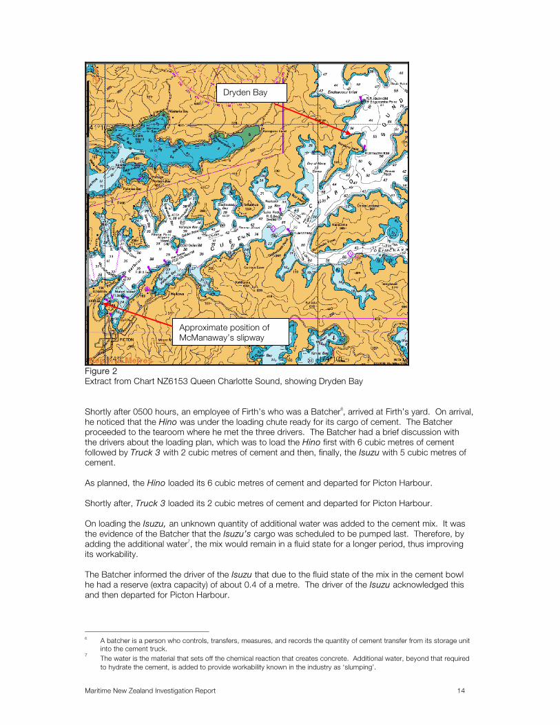
Figure 2 Extract from Chart NZ6153 Queen Charlotte Sound, showing Dryden Bay Shortly after 0500 hours, an employee of Firth’s who was a Batcher6, arrived at Firth’s yard. On arrival, he noticed that the Hino was under the loading chute ready for its cargo of cement. The Batcher proceeded to the tearoom where he met the three drivers. The Batcher had a brief discussion with the drivers about the loading plan, which was to load the Hino first with 6 cubic metres of cement followed by Truck 3 with 2 cubic metres of cement and then, finally, the Isuzu with 5 cubic metres of cement. As planned, the Hino loaded its 6 cubic metres of cement and departed for Picton Harbour. Shortly after, Truck 3 loaded its 2 cubic metres of cement and departed for Picton Harbour. On loading the Isuzu, an unknown quantity of additional water was added to the cement mix. It was the evidence of the Batcher that the Isuzu’s cargo was scheduled to be pumped last. Therefore, by adding the additional water7, the mix would remain in a fluid state for a longer period, thus improving its workability. The Batcher informed the driver of the Isuzu that due to the fluid state of the mix in the cement bowl he had a reserve (extra capacity) of about 0.4 of a metre. The driver of the Isuzu acknowledged this and then departed for Picton Harbour.
6 A batcher is a person who controls, transfers, measures, and records the quantity of cement transfer from its storage unit
into the cement truck. 7 The water is the material that sets off the chemical reaction that creates concrete. Additional water, beyond that required
to hydrate the cement, is added to provide workability known in the industry as ‘slumping’.
Dryden Bay
Approximate position of McManaway’s slipway

Maritime New Zealand Investigation Report 15
At about 0540 hours, the Hino arrived at Picton Harbour followed shortly afterwards by Truck 3. After checking through port security, the drivers prepared their respective trucks for the transfer of cement from Truck 3 into the Hino. Truck 3 parked on Waitohi Wharf (See Figure 3 - Extract of Chart NZ6154 Tory Channel Entrance and Picton Harbour showing Picton Wharves) and the Hino parked on spoil land that was located adjacent to and below Waitohi Wharf. Truck 3, using a chute, that was an integral part of the truck, commenced the transfer of cement into the Hino. The driver of the Hino monitored the capacity remaining in the mixing bowl and advised the driver of Truck 3 accordingly.
Figure 3 Extract of Chart NZ6154 Tory Channel Entrance & Picton Harbour, showing Picton Wharves The driver of Truck 3 was told by the driver of the Hino that there was plenty of space remaining in the mixing bowl of his truck. For this reason, they continued transferring the cement and in doing so discharged, unintentionally, the full two metres of cement into the bowl of the Hino. As the whole two cubic metres from Truck 3 was pumped into the Hino, this meant instead of the Isuzu and Hino carrying 6 and 7 cubic metres respectively, they carried 5 and 8 cubic metres respectively. The Hino’s mixing bowl now contained 8 cubic metres of cement, which equated to about 19.6 tonnes. The gross laden weight of the truck was estimated to be about 30.6 tonnes. The maximum bowl capacity of the Hino was 8.5 cubic metres.
Approximate position of Santa Regina about the time of the accident.
Ro Ro berths
Approximate position of McManaway’s Slipyard
Approximate position of Trucks on transfer of cement from Truck 3 into the Hino
Waitohi Wharf

Maritime New Zealand Investigation Report 16
The tare weight of the Hino was 11.04 tonnes. The calculated weight of cement was 19.6 tonnes. Therefore, the overall weight of the truck was estimated to be 30.64 tonnes. The manufacturer’s gross laden weight for the Hino was 28.6 tonnes. When New Zealand Police weighed the truck after the accident, the weight recorded was 31.5 tonnes, which is very close to the estimated calculation. When Police weighed the truck following the accident, the truck’s fuel tanks and other parts had been removed. Firth calculated the weight of the Hino to be 29.2 tonnes, determined by loading an exact replica of the Hino with the same quantity of concrete. Firth stated that 29.2 tonnes was within 2% of the manufacturer’s limits, which the manufacturer confirmed as being an acceptable tolerance. Firth state the Police weights are incorrect. However, based on the evidence of the Police, Maritime NZ does not accept Firth’s calculation in relation to the Hino’s weight. In any case, the gross laden weight permitted for the Hino while driving on a road was 26.88 tonnes (section 4 of Land Transport Rule 41001: Vehicle Dimensions & Mass 2002). Section 5 of Land Transport Rule 41001: Vehicle Dimensions & Mass 2002 allows vehicle operators to apply for a permit to carry heavier loads on roads than allowed under section 4. However, such a permit does not allow an operator to carry heavier loads than the manufacturer’s maximum gross laden weight for the vehicle. Shortly after completing the transfer of cement into the Hino, an employee of Crafar Crouch arrived at Waitohi wharf in the Pump Truck. As stated, the Pump Truck was going to travel on the barge, together with the Isuzu and the Hino, to Dryden Bay. The driver of the Pump Truck had a brief conversation with the drivers of the Isuzu and the Hino and was told they had transferred the additional 2 cubic metres of cement into the Hino. Afterwards, the driver of the Pump Truck continued on to McManaway’s Slipway (See Figure 3 - Showing McManaway’s loading bay). As the driver of the Hino busied himself in preparation for proceeding to McManaway’s slipway, the Isuzu arrived at Waitohi Wharf. The driver of Truck 3, who was preparing his vehicle to return to Firth’s yard, informed the driver of the Isuzu that there was no concrete left to transfer into the Isuzu (all his concrete having been transferred to the Hino). The driver of the Isuzu acknowledged this and continued to the slipway, followed by the Hino.
Rakanui & Mac III At about 0545 hours on 19 August, the Skipper and Deckhand of Rakanui prepared for the arrival of the Isuzu and the Hino and the Pump Truck. Two days earlier, the Skipper had been told by the Managing Director of McManaway’s that Rakanui and Mac III were to be ready at 0600 hours on 19 August to load the Isuzu and the Hino and a Pump Truck and transport them to Dryden Bay. At about 0550 hours, the Skipper checked the moorings of Mac III and adjusted them in readiness for loading. He instructed the Deckhand to lower Mac III’s loading ramp onto the adjacent slipway. After the ramp was lowered, the Skipper made Rakanui fast on the starboard side of Mac III (See Figure 4 - showing Mac III with her loading ramp on the slipway with Rakanui fast on the starboard side)8. The Skipper stated that it was still dark at this time with good visibility, light winds and a slight sea. Mac III’s deck and ramp were coated with a heavy dew. The tidal conditions were a mid ebb tidal stream running in a north easterly direction at a rate of about half a knot. Mac III’s loading ramp was lying horizontal and level with the adjacent wharf. At the time of loading the source of deck lighting for
8 The Skipper and the Deckhand, when referring to the respective sides of the barge, did so from the perspective of looking
at the barge as would a driver when his truck was being loaded. In fact, the bow of the barge was on the shoreward end when viewed in Figure 4, such that Rakanui would have been made fast on Mac III’s port side and not starboard as is stated in the report.

Maritime New Zealand Investigation Report 17
the barge was from the headlights of the trucks. The searchlight on Rakanui could not be used as this was located above the deck of the barge and would have blinded the truck drivers.
Figure 4 Showing Mac III with loading ramp on the slipway with Rakanui fast on the starboard side
Discussion Regarding Loading Sequence Shortly after 0550 hours, the drivers of the Pump Truck and the Isuzu and the Hino arrived at the gate leading to McManaway’s slipway. The Hino drove down the slip in readiness for loading. The driver of the Pump Truck told the Firth’s drivers to wait, while he spoke to the Skipper of Rakanui about the loading plan. The Skipper told the Pump Truck driver that the lightest truck (Isuzu) was to be loaded first on the port side of Mac III. The Pump Truck driver agreed but pointed out to the Skipper that the barge would list in the direction of the bow of the Tiro I, which was an unrelated ship tied adjacent to the barge. The Skipper agreed there may be a risk of the truck contacting the bow of Tiro I and so, to mitigate any risk and ameliorate the Pump Truck driver’s concern, the loading plan was amended as follows:
• The Isuzu was to be loaded first onto Mac III and positioned on the starboard side forward (See Figure 5 - Showing proposed loading plan on Mac III) and,
• The Hino was to be loaded next and positioned on the port side, forward (Figure 5 - Showing proposed loading plan on Mac III), adjacent to the Isuzu and,
• The Pump Truck was to be loaded last, on the centre line of the barge at the after end of Mac III (See Figure 5 - Showing proposed loading plan on Mac III).
The Hino then reversed up the slipway to allow the lightest truck (the Isuzu) to be loaded first on the starboard side of the barge.
Mac III
Tiro I
Loading ramp
Rakanui
Maritime New Zealand Investigation Report 18
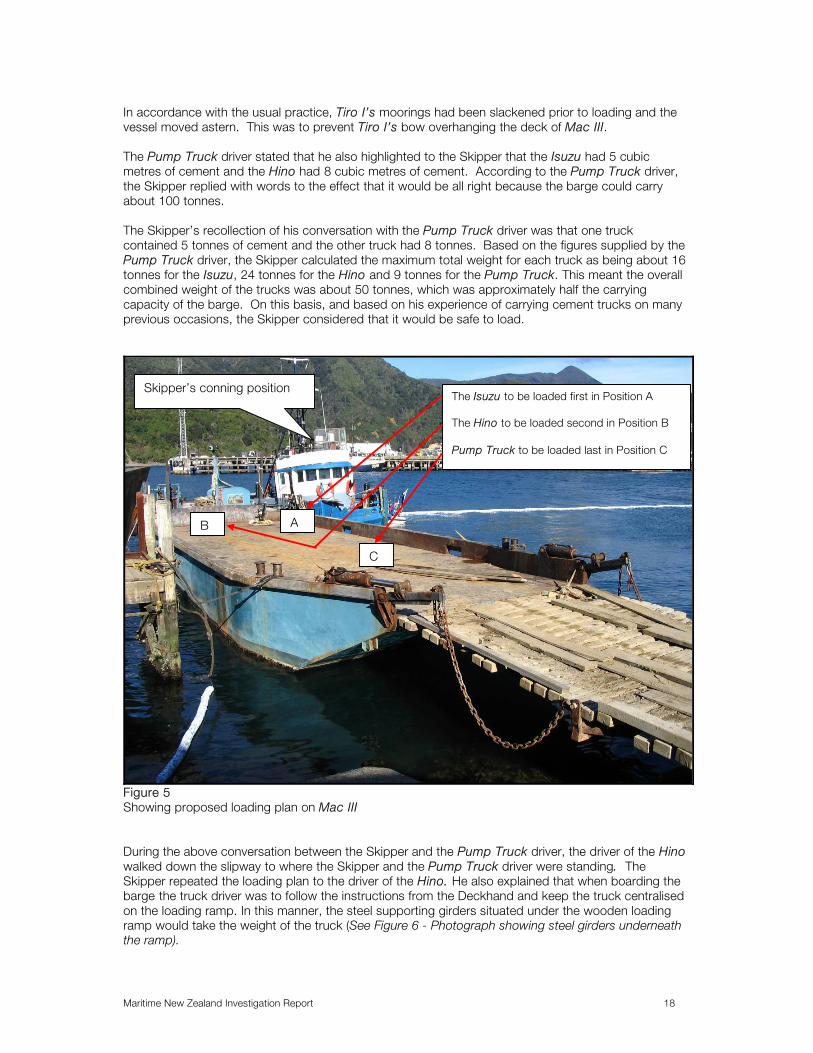
In accordance with the usual practice, Tiro I’s moorings had been slackened prior to loading and the vessel moved astern. This was to prevent Tiro I’s bow overhanging the deck of Mac III. The Pump Truck driver stated that he also highlighted to the Skipper that the Isuzu had 5 cubic metres of cement and the Hino had 8 cubic metres of cement. According to the Pump Truck driver, the Skipper replied with words to the effect that it would be all right because the barge could carry about 100 tonnes. The Skipper’s recollection of his conversation with the Pump Truck driver was that one truck contained 5 tonnes of cement and the other truck had 8 tonnes. Based on the figures supplied by the Pump Truck driver, the Skipper calculated the maximum total weight for each truck as being about 16 tonnes for the Isuzu, 24 tonnes for the Hino and 9 tonnes for the Pump Truck. This meant the overall combined weight of the trucks was about 50 tonnes, which was approximately half the carrying capacity of the barge. On this basis, and based on his experience of carrying cement trucks on many previous occasions, the Skipper considered that it would be safe to load.
Figure 5 Showing proposed loading plan on Mac III During the above conversation between the Skipper and the Pump Truck driver, the driver of the Hino walked down the slipway to where the Skipper and the Pump Truck driver were standing. The Skipper repeated the loading plan to the driver of the Hino. He also explained that when boarding the barge the truck driver was to follow the instructions from the Deckhand and keep the truck centralised on the loading ramp. In this manner, the steel supporting girders situated under the wooden loading ramp would take the weight of the truck (See Figure 6 - Photograph showing steel girders underneath the ramp).
Skipper’s conning position
B A
C
The Isuzu to be loaded first in Position A The Hino to be loaded second in Position B Pump Truck to be loaded last in Position C

Maritime New Zealand Investigation Report 19
Figure 6 Photograph showing steel girders underneath the ramp (Photograph taken by SGS M&I several days after the accident during ramp survey. Note – at the time of the accident the ramp was lying horizontally in relation to the barge and shore.) The driver of the Hino acknowledged the Skipper’s instructions. He then started to walk back up the slipway towards his truck. Whilst walking up the slipway, the driver of the Hino had a brief conversation with the Pump Truck driver about a ferry approaching Picton. The ferry was heading for the Ro Ro berths situated to the south east of the slipway, where Mac III was moored (See Figure 3 - Positions of berths). The driver of the Hino asked the Pump Truck driver the name of the approaching ferry and was told it was the Santa Regina9. Following this, the driver of the Hino continued walking up the slipway (See Figure 3 - approximate position of Santa Regina). The Pump Truck driver then saw the drivers of the Isuzu and the Hino talking to each other for a short time.
Loading the Barge At about 0600 hours, the Skipper of Rakanui was standing on the flying bridge of the tug (See Figure 5 - Position of flying bridge). He had applied three quarters of Rakanui’s engine power to push Mac III’s loading ramp hard up against the slipway in preparation for loading the trucks. This was standard practice with all barge operators throughout the Marlborough Sounds. At about 0602 hours, the driver of the Isuzu drove his truck down the slipway towards the loading ramp of the barge. The Pump Truck driver, who was on the slipway, had a brief conversation with the
9 The Pump Truck Driver was referring to the passenger ferry Santa Regina. She was inward bound and due to dock at
about 0615 hours on the Bluebridge berth (See Figure 3 - for position). She was approaching the turning circle on a south westerly heading at a speed of about 9 knots.
Steel girders underneath ramp

Maritime New Zealand Investigation Report 20
driver of the Isuzu about the loading plan. Neither the Skipper nor the Deckhand communicated verbally with the driver of the Isuzu at this time. The Deckhand stated that he was using hand signals to guide the Isuzu onto Mac III. As he was guiding the Isuzu into position, the Hino, without having received any instructions from the Deckhand, started to drive onto the loading ramp. The Skipper shouted to the Deckhand to stop the Hino from boarding the barge. This was done and the Hino reversed back down the loading ramp10. The Deckhand finished loading the Isuzu into position on the forward starboard side of the barge without incident. The driver remained inside his cab in case it was necessary to reposition the Isuzu and allow more space for the Hino (See Figure 5 - Position A for the Isuzu). The Skipper and Deckhand stated that when the Isuzu was loaded into position on the barge, Mac III was listed to starboard by about 10°. According to the Skipper, this degree of list was normal when the first of the cement trucks had previously been loaded onto the barge. After the Isuzu was in position, the Deckhand instructed the driver of the Hino to board Mac III. The Pump Truck driver stated that at or about the time the Hino started to board Mac III, he went back to his vehicle, at the top of the slipway, in preparation for boarding the barge. It was his opinion that the driver of the Hino drove on to the ramp too quickly and he assumed the Deckhand would instruct the driver to slow down. The Deckhand, who was positioned on the deck of the barge just forward of the Isuzu, (See Figure 5 - Position of the Isuzu), did not consider the Hino’s speed to be excessive. The Deckhand stated that the driver of the Hino drove the truck up the centre of the ramp as instructed by the Skipper, prior to the load commencing. The Skipper stated he did not consider the Hino’s speed to be excessive whilst traversing the ramp. The Skipper also stated that the weight transfer of the Hino onto the ramp had the effect of reducing Mac III’s list to starboard. As the Hino approached the top of the loading ramp and the front wheels of the truck reached the steel deck of the barge, the Deckhand recalled the driver was looking down at something in his cab and not paying full attention to his loading instructions to move over onto the port side of the barge. As the Hino continued to move forward onto the deck of Mac III, the Deckhand continued to signal unsuccessfully to the driver to manoeuvre his truck to the port side of the barge to offset the starboard list caused by the Isuzu. However, contrary to this instruction the driver began to turn his truck in the opposite direction, towards the starboard side of the barge. The Deckhand eventually gained the driver’s attention by yelling out and pointing to port, in the direction of where he wanted the truck to go. The driver of the Hino, as directed by the Deckhand, then started to manoeuvre his truck over onto the port side of the barge. Whilst the Skipper and the Deckhand could not recall by how much the barge was listing at this time, neither of them considered this to be more than usual; otherwise they would have immediately stopped the loading operation. The Skipper and Deckhand stated that as the driver of the Hino had started to turn towards the port side of the barge, a juddering noise was suddenly heard coming from the barge. Almost immediately after hearing this noise, the rear end of the Hino started to slide to starboard, towards the low side of the barge. The Skipper stated that at the time of the judder the Hino was stopped. In addition, during the slide, he noticed that none of the wheels of the truck were turning. This evidence was supported by Police diver photographs, which showed the skid marks on the tyres on the deck of the barge were positioned 90° to the tread pattern of the tyres. As the Hino continued to slide to starboard the list of the barge and the momentum of the Hino increased.
10 During the course of his interview the Pump Truck driver stated that he gave the instruction to the driver of the Hino to
drive onto the ramp and then wait for instructions from the Deckhand. The reason behind the Pump Truck driver’s instruction was that in the past this was the loading sequence which he had witnessed.

Maritime New Zealand Investigation Report 21
Due to the increasing list of the barge and to stop himself from sliding across the deck of the barge, the Deckhand turned around and grabbed hold of a stanchion situated on the port bulwark of Mac III. The Skipper, who was still on the flying bridge of the tug, saw the Hino sliding towards the barge’s starboard bulwark. He stated that the right rear axle hit the bulwarks at or near the hinge point of the starboard ram (used to lift the ramp). The barge’s list continued to increase. The Skipper stated that the front of the Hino appeared to slide in an arc to starboard. At this point, in an attempt to ameliorate the situation he applied full engine revolutions and put Rakanui’s wheel hard to port to provide an opposing force on the starboard side of the barge. When the rear of the truck made contact with the bulwark, the front of the truck did the same, and the Skipper saw the Hino topple over the bulwark and into the water. Seconds after the Hino had toppled over the side, the Skipper saw the Isuzu also toppling over the top of the starboard bulwark. Before the Isuzu struck the surface of the water it collided with the starboard bow of Rakanui causing damage to the tug (See Figure 7 – Photograph of damage to Rakanui). The force from the trucks toppling over the bulwark caused the tug’s forward spring mooring line to part, which in turn caused Rakanui’s bow to swing to port away from Mac III (See Figure 7 - Photograph of damage to Rakanui’s bow). The Skipper stated that immediately after the Isuzu had collided with Rakanui, he reduced the engine revolutions to a minimum and turned on the spotlight11 in the direction of where the trucks had fallen into the water. Due to the depth of water, which was about 7 metres, he could not see anything. The Skipper then instructed the Deckhand to call the Police and an ambulance. At or about the time the two trucks fell into the water the Pump Truck driver was reversing down the slipway and did not witness the accident. The Skipper, Deckhand, and Pump Truck driver made a valiant but unsuccessful effort to assist the drivers of the two cement trucks. However, by the time diving equipment was mustered and a full rescue attempt was made, both drivers had drowned.
Figure 7 Photograph showing damage to the starboard bow of Rakanui
11 This was to illuminate the water, as it was morning twilight.

Maritime New Zealand Investigation Report 22
COMMENT & ANALYSIS
Evidence On 19 August 2005, Maritime New Zealand commenced an investigation into the accident, which resulted in the loss of life of Allan Tempero, the driver of the Hino and Thomas Phillips, the driver of the Isuzu. Maritime New Zealand Investigators interviewed the following people:
• Skipper and Deckhand of Rakanui & Mac III
• Management of McManaway (the owner of Rakanui & Mac III)
• Management and employees of Firth / Fletcher Concrete and Infrastructure Limited (the operator/owner of the cement trucks and the employer of Allan Tempero and Thomas Phillips)
• Management and employees of Crafar Crouch (the company who contracted with Firth’s and McManaway)
• Allied Concrete Truck Drivers (a company which had most regularly over recent years contracted concrete trucks to travel on McManaway barges)
Documentation was also obtained from:
• Port Officials at Picton
• Firth
• Crafar Crouch
• McManaway
• Maritime New Zealand
• SGS-M&I - surveying company
• New Zealand Police
Analysis History McManaway has been operating barges in the Marlborough Sounds for about 15 years. They have a total of five employees. Prior to this accident, McManaway had been involved in hundreds of tug and barge voyages throughout the Marlborough Sounds, carrying amongst other things, plant and building materials. Analysis of McManaway’s tug logbooks indicates that in the 13 years preceding the accident, McManaway undertook 673 round voyages carrying trucks. 235 of these voyages involved the carriage of concrete trucks. McManaway has been the subject of one previous accident investigation conducted by Maritime New Zealand. This occurred in 2000 when one of McManaway’s tugs (Tuahine), which was engaged in towing a barge in ballast, foundered in a seaway. McManaway did not own the barge being towed by Tuahine. Maritime New Zealand concluded that no blame should be apportioned to the crew of the tug in that case. Firth was established in May 1925. In March 1979, Fletcher Challenge purchased Firth. In March 2001, Firth became a division of Fletcher Concrete and Infrastructure Limited, a wholly owned subsidiary of Fletcher Building Limited. Firth has a workforce of about 800 employees working in more than 70 plant sites throughout New Zealand, delivering concrete products, systems and solutions to customers throughout the country.

Maritime New Zealand Investigation Report 23
Legislation In New Zealand, a number of statutes and Maritime Rules govern the operation of commercial vessels, such as the tug Rakanui. The Rules also include minimum standards for seafarers’ qualifications to operate these vessels. At the time of the accident, Rakanui‘s certification was verified by Maritime NZ Investigators and found to be compliant with the Maritime Rules. The Skipper and Deckhand’s certification were also verified and found to be compliant with the Maritime Rules.
Maritime Rule Part 40C - Design, Construction and Equipment – Non SOLAS, Non-Passenger Ships Section 4 of Rule Part 40C sets out the design, construction and equipment requirements for barges. Rule 40C.69 states that section 4 of Rule Part 40C applies as follows:
(1) Rule 40C.71(1) and 40C.72 to 40C.83 inclusive, apply to-
(a) a New Zealand barge of 24 metres or more in length that carried for hire and reward any cargo, waste, dredging or other material; and
(b) a barge that carries persons on board during the course of a voyage (Maritime NZ emphasis) within New Zealand waters; and
(2) Rule 40C.71(2) applies to a new barge that is fitted with or carries a crane that has a safe
working load of more than 1 tonne. Rule Part 40C.71 states:
(1) A barge to which Rule 40C.69(1) applies must meet the construction requirements in Rules 40C.9(1) to (4) inclusive and Rule 40C.9(8).
(2) A barge to which Rule 40C.69(2) applies must meet the stability requirements of Clause
(3) Appendix 1 of this Part. It is only if a barge is fitted with a crane that has a safe working load of more than one tonne, that it will be required to meet any of the intact stability requirements in Appendix 1 of Maritime Rule Part 40C. A barge that is fitted with a crane that has a safe working load of more than one tonne is required to meet the intact stability requirements of Clause 3 of Appendix 1 of Maritime Rule Part 40C. Under Clause 3 of Appendix 1 of Maritime Rule Part 40C a barge is required to undergo a tilting test, but not an inclining test. It is unlikely that any stability issues in relation to Mac III during the loading operation would have been discovered, unless it had undertaken an inclining test prior to the accident. However, there is no requirement under Maritime Rule Part 40C for a barge to undergo an inclining test, irrespective of its size or whether it carries passengers. Mac III was not required to comply with the other design, construction and equipment requirements of Maritime Rule 40C because:
• It is less than 24 metres in length,
• It does not carry persons/passengers on board during the course of a voyage.
During the course of this investigation, there was conflicting evidence obtained as to the practice of carrying truck drivers on McManaway barges, i.e., it appears this occurred on occasion.

Maritime New Zealand Investigation Report 24
The Managing Director of McManaway stated that he had instructed the Skippers of his tugs not to allow truck drivers to ride on the barge, when it was being towed astern of the tug. Truck drivers employed by Allied Concrete confirmed that this instruction was strictly enforced by McManaway skippers. This was based on the operating limits specified on Mac III’s SSM Certificate12 which stated “nil persons to be carried whilst on board under tow”. When Mac III was being pushed by the tug13 in good weather, the drivers from Allied Concrete would work between the tug and barge. However, Allied truck drivers stated that in bad weather, the Skippers insisted that they had to travel on the tug and not the barge. Evidence obtained from Firth was that the drivers of their trucks were regularly carried on the barge. However, the Managing Director of McManaway stated that the intended voyage on 19 August was the first time in many years that any of Firth’s trucks had been carried on a McManaway barge. Had Maritime NZ become aware of drivers being carried as passengers on Mac III during commercial voyages, the likely consequence would have been enforcement of the prohibition on carrying passengers, for example, by imposing conditions on the barge under section 43 of the Maritime Transport Act 1994. The alternative would have been for McManaway to comply with the requirements for passenger carrying under Maritime Rule Part 40C. However, it would have been impractical for McManaway to convert the Mac III into a passenger carrying barge that complied with Maritime Rule Part 40C, given the barge’s intended purpose. For example, to comply with Maritime Rule Part 40C, Mac III would have required life saving appliances for passengers and crew, fitting bulwarks or guard rails to any deck or part of a deck that persons had access to, installing a bilge system, complying with requirements for radio communications, crew accommodation, complying with detailed rules on constructions, shelter and seating requirements and complying with requirements relating to egress head room and toilets. Even if all necessary modifications had been undertaken to ensure that Mac III complied with the requirements of Maritime Rule Part 40C for passenger carrying barges, those modifications would not have related to the stability of the barge. As stated above, the only barges that are required to comply with any of the intact stability requirements of Maritime Rule Part 40C, are barges that have been fitted with a crane that has a safe load of more than one tonne. Mac III was not fitted with a crane and was not therefore required to comply with the intact stability requirements of Maritime Rule Part 40C. The requirements of Maritime Rule Part 40C relating to barges carrying persons, applied to a barge carrying “any person on board during a voyage within New Zealand waters”. This accident did not occur during a voyage, but rather while it was stationary alongside the wharf. The accident occurred during the loading operation on 19 August. The truck drivers were not “passengers” for the purposes of Maritime Rule Part 40C14 during the loading operation.
Maritime Rule Part 47 Maritime Rule Part 47 – Load Lines - covers the load line rules (the stability requirements of a vessel). Section 47.60 (See Appendix 6 – Rule) covers ships under 24 metres in length. Mac III was not required to comply with this Rule due to the fact that Mac III was not designed or ever intended to be a passenger carrying barge. The barge was not certified to carry passengers/ persons on board during the course of a voyage. Rules 47.60 and 47.61 (See Appendix 6 – Rule) state as follows:
• Section 47.60 - Compliance with Section 2
The owner and Master of a ship to which section 2 applies must not allow the ship to proceed on a voyage unless-
12 See Footnote 2 13 When a barge is being pushed by a tug, the mooring arrangement is such that the tug is physically tied alongside the
barge (See Figure 1 – for an example of a pushing arrangement). 14 “Passenger” is defined in Rule 40C.2 as meaning ''… any person carried on a ship, other than—
(a) The master and members of the crew, and any other person employed or engaged in any capacity on board the ship on the business of the ship: …”

Maritime New Zealand Investigation Report 25
(a) it is surveyed and maintained in accordance with the requirements of Rule 47.66; (See Appendix 6 – Rule) and
(b) it is marked –
(i) in accordance with the requirements of Rule 47.64 (See Appendix 6 – Rule); or
(ii) for an existing New Zealand ship, with a submersion line in accordance with the requirements of Part VI of the Shipping and Seamen Act 1952 or the provisions of Part 10 of the Maritime Transport Act 1994; and
(c) there is held in respect of that ship –
(i) a valid New Zealand Load Line Certificate issued in accordance with the provisions of Rule 47.67 (See Appendix 6 – Rule); or
(ii) for an existing New Zealand ship, a current submersion line certificate issued under Part IV of the Shipping and Seamen Act 1952 or Part X of the Maritime Transport Act 1994.
• 47.61 - Application of Section 2
Section 2 applies to any ship of less than 24 metres in length that carries cargo on a voyage that is- (a) a New Zealand ship, or foreign ship that operates on the New Zealand coast; and
(b) a decked ship, or a barge carrying persons on board during a voyage.
If Mac III was deemed to be carrying persons on board under section 2 of Maritime Rule Part 47, freeboard would have to be assigned to the barge and load lines marked on it. However, although a stability analysis would be involved in determining freeboard and load lines, no stability booklet would have to be created and it would not have been required to undergo a full inclining experiment. In the absence of a full inclining experiment, it is unlikely that any issues in relation to Mac III’s stability during loading operations would have been discovered.
Other Maritime Rules Maritime Rule Part 40C.82 states that “a barge that carries passengers on board during a voyage must meet the requirements of Rules 40A.12 to 40A.21 inclusive and Rules 40A.25 and 40A.42”. Maritime Rule Part 40A sets out requirements relating to the design, construction and equipment of passenger ships which are not SOLAS15 ships. Maritime Rule Part 40A.13 states that certain ships have to meet the intact stability of Appendix 1 of Rule Part 40A. Those stability requirements are essentially the same as the intact stability requirements of Appendix 1 of Rule Part 40C. However, Rule 40A.13 does not apply to existing ships that were surveyed and issued with a certificate of survey prior to 1 February 1998 (Rule 40A.13(a) and Rule 40A.14). Mac III was an existing ship that was surveyed and issued with a certificate of survey prior to 1 February 1998. Accordingly, even if Mac III was carrying passengers during voyages for the purposes of Rule 40C.82 and was therefore required to comply with Rules 40A.12 to 40A.21 and Rules 40A.25 and 40A.42, it would not have had to comply with the intact stability requirements of Appendix 1 of Rule 40A. As
15 SOLAS ships in general are passenger ships engaged on an international voyage or non-passenger ships of 500 gross
tonnes or more engaged on an international voyage.

Maritime New Zealand Investigation Report 26
stated above, in the absence of a full inclining experiment, it is unlikely that any issues in relation to Mac III’s stability during loading operations would have been discovered. Maritime Rule Part 21 – Safe Ship Management Systems (See Footnote 1), would not apply to Mac III unless it carries persons on board during the course of a voyage. Assuming persons were carried on board Mac III during the course of a voyage, there would be no requirement under Rule Part 21 for Mac III to undergo a full inclining experiment. Accordingly, even if Mac III had been required to comply with Rule Part 21 it is unlikely that any issues in relation to Mac III’s stability during loading operations would have been discovered.
Stability Criteria Developed by Ministry of Transport (MOT86) Historically, it has been recognised that it is impractical to apply the stability criteria for ships to barges. For example, barges could not comply with the SOLAS16 stability requirements unless strict loading conditions were applied. If such conditions were applied this would render barges impractical for their intended use. This was due to the fact that SOLAS stability requirements are based on ships of conventional form (round hull ships). Barges do not fall into this category as they have a flat bottom. For this reason, Classification Societies adopted more practical stability criteria for deck loaded pontoons or barges with a block coefficient exceeding 0.917. Similar stability criteria were adopted by the New Zealand Ministry of Transport in 1986. These criteria are commonly referred to as “MOT86”. Maritime NZ allows survey companies to use the MOT86 stability criteria when determining whether or not a barge is fit for purpose and no stability criteria in the Maritime Rules apply (See Appendix 1 - Limiting KG curves shows the difference between SOLAS and MOT86 criteria). MOT86 is more practical for a flat bottom barge as it allows more latitude for load configurations.
Analysis of the Loading Sequence Prior to the Accident & its Effect on Mac III’s Stability As this accident involved the loading of weights onto the deck of Mac III, the importance of ascertaining stability data was crucial in order to determine the causal factors that led to the accident. On 29 August 2005, Maritime New Zealand, as part of its investigation, contracted SGS-M&I to conduct an inclining experiment18 on board Mac III. SGS-M&I then calculated the transverse statical stability19 of Mac III using the following data:
• Results from the inclining experiment.
• The weights of the trucks - supplied by New Zealand Police.
• The evidence of the Skipper and Deckhand.
• Accident scene information - supplied by the New Zealand Police.
• Expert (Land Transport New Zealand (LTNZ)) opinion on the coefficient of friction of Mac III’s deck.
• Dimensions of the Isuzu and Hino - supplied by Firth.
A barge, such as Mac III, may be regarded as a hollow shell, to which weights may be added, removed, or shifted about the deck. Thus, the position of the centre of Gravity “G”20 will change
16 SOLAS – The International Maritime Organisation Convention for the Safety of Life at Sea. 17 In layman term’s, this means a barge with a rectangular hull. 18 This is performed to find the barge’s light GM and hence the light KG. It consists of shifting weights transversely across
the deck of a ship when the ship is free to heel. 19 Transverse statical stability is governed principally by (a) The position of the barge’s centre of gravity (C of G) and (b) the
form of the barge. The position of the C of G depends on the loading of cargo and the distribution of other weights in the barge.

Maritime New Zealand Investigation Report 27
depending on how the barge is loaded and must be calculated each time for a barge’s stability to be found. The transverse21 and longitudinal22 stability of a barge are always considered separately. This accident involved the loading of weights onto the deck of a barge, namely:
• The Isuzu, which weighed about 21 310 Kg, was the first truck to be loaded. Once loaded, its position was to starboard of the centre line of the barge (transverse stability). According to the inclining experiments conducted after the accident, the added weight from the Isuzu would have caused Mac III to list 9.5° to starboard (See Appendix 1 - Mac III Dumb Barge Inclining Experiment & Stability Report 29 August 2005 Loadcase 2).
When interviewed by Maritime NZ both the Skipper and Deckhand stated that the barge was listing about 10° to starboard after the Isuzu was loaded, which is very close to the stability calculations that were conducted after the accident.
• The Hino, which weighed about 31 500 Kg23, was loaded after the Isuzu. As the Hino drove up the loading ramp its weight would initially have been distributed between the barge and the adjacent wharf. This would have had an effect of reducing the starboard list of the barge at this time. This is confirmed by the Skipper who stated that as the Hino drove up the ramp Mac III’s starboard list decreased.
• The Deckhand stated that as the Hino approached the top of the loading ramp and its front
wheels reached the steel deck of the barge, the Hino was centralised on the loading ramp. At this point the driver looked down at something in his cab and was not paying full attention to the Deckhand’s signals to move over onto the port side of the barge.
• The Deckhand continued unsuccessfully to attract the attention of the driver both verbally and
by hand and direct him towards the port side of the barge in order to counterbalance the weight of the Isuzu and bring Mac III upright.
• As the Hino continued to move onto the steel deck of Mac III, the Deckhand stated that the
driver was still not paying full attention and began to turn his truck to starboard and not to port as he had been directed.
The Deckhand stated that by the time he managed to gain the driver’s attention, the majority of the Hino was on or nearly on the steel deck of Mac III24. The New Zealand Police concluded from their analysis of skid marks on the barge that at the time that the Hino started to slip sideways towards the starboard side of the barge the “fourth (rearmost) axle of the concrete truck (the Hino) was not on the barge. It was still on the ramp. The right hand side wheels on the third axle were just on the deck of the barge, while the left side wheels were still on the ramp”. At this point, a major part of the weight of the Hino would have been transferring from the ramp onto the deck of the barge. This ‘load transfer’ was the critical stage of the loading. The combined effect of the height and weight of the Isuzu on the forward starboard quarter of the barge, and the height and weight of the Hino, coupled with its offset to starboard of the barge’s centreline, would have caused the barge to list further to starboard. Moreover, the effect of the rotation of the cement bowls of the two trucks would have caused the centre of gravity of the concrete to rise as it was moved to
20 Centre of gravity of a Ship “G” is often defined as the point through which all the weight of the ship is considered to act
vertically downwards. 21 The movement of weights from port to starboard or vice versa. 22 The movement of weights from forward to aft or vice versa. 23 Weight supplied by New Zealand Police. As stated earlier, Firth stated that the police weights are incorrect. 24 From the Deckhand’s sighted position, his field of vision would be such that it would be difficult to see if the truck was fully
on the deck of the barge.
Maritime New Zealand Investigation Report 28
the side of the bowls25. This would have also caused a shift in weight, contributing to the destabilising factor. The Deckhand stated that on gaining the driver’s attention, the driver started to turn his truck towards the port side of the barge. At this point, both the Skipper and Deckhand suddenly heard a noise and felt the barge ‘judder26’. With the majority of the weight of the Hino on the steel deck of the barge, any restraining effect on the list of Mac III, whilst the Hino was on the ramp, would have disappeared. In turn, any residual positive stability of the barge would have been lost causing the barge to list further to starboard. As the barge continued to list further, the frictional resistance between the Hino’s wheels and the barge deck/ramp was overcome, causing the Hino to slide to starboard. The Deckhand stated that at or about the time of the judder, the Hino started to slide to starboard, “like he was on ice or something, the truck started sliding sideways to the left of the barge”27 (i.e. the right, looking from the ramp end) Neither the Skipper nor the Deckhand could recall by how much the barge was listing at the time the Hino started to slide. Neither the Skipper nor the Deckhand considered the list to be greater than what they had normally experienced in the past. The Skipper stated that the method of loading on 19 August was standard practice on McManaway barges and was one that had been used for many years without incident. As noted previously, the tug’s log books indicate that between 1992 and 19 August 2005, McManaway undertook 673 round voyages carrying trucks of which 235 involved the carriage of concrete trucks without incident. Two days prior to this accident two Allied Concrete trucks and a pump truck were loaded onto Mac III in the same manner and transported without incident. To ascertain the causal factors that caused the Hino to slide to starboard the following data needed to be established:
• Mac III’s stability condition during loading.
• The coefficient of friction28 relating to the loading conditions on the morning of the accident, i.e., the conditions underfoot.
Summary of Mac III’s Statical Stability During the Course of Loading As stated above, Mac III was not required to comply with any stability requirements under the Maritime Rules and MOT86. Maritime NZ requested SGS-M&I to carry out stability analyses to determine the degree of stability of the barge in various loading and loaded conditions. The full results of these analyses can be found in Appendix 1 of this report.
25 The rotation of the bowls were anticlockwise, this not only caused a rise in G but also it had the effect of moving G to the
starboard side of Mac III as the mix was lifted during rotation. 26 Where the judder emanated from is unresolved. One theory is that the judder may have been caused by the sudden shift
in the balance of the Hino’s weight onto the deck of the barge namely, the full weight of the Hino transferring onto the deck of Mac III. This shift would have caused Mac III’s C of G to rise accordingly. This rise would have reduced the GZ righting lever thus increasing the barge’s list to starboard. This increase in list may have caused the high side of the ramp (port) to lift off the wharf (the ramp was an integral part of Mac III). As the ramp lifted off the wharf the chain preventers, which were securing the ramp to the wharf, may have slid on the steel bollards. The sliding of the chain preventers may have caused the ramp to judder. Maritime NZ does not believe that the judder was caused by the rearmost axle of the Hino breaking the cantilevered transverse wooden ramp cladding as this would have occurred after the Hino started to slide from her initial centralised location on the loading ramp.
27 The Deckhand was facing aft so the “left of the barge” would have been the starboard side. 28
This figure would give the angle heel, at which the barge needed to be for the Hino to start to slide.

Maritime New Zealand Investigation Report 29
SGS-M&I analyses are based on the recommended minimum guidance (Maritime NZ emphasis) values for intact stability as set out in Maritime Rule Part 40C Design, Construction and Equipment Non SOLAS Non Passenger Ships Appendix 1 – Intact Stability and MOT8629 (See Appendix 5 – Intact Stability). Mac III’s actual stability data was then compared with the recommended minimum values. SGS-M&I first considered the free floating condition of Mac III with the Isuzu loaded on the forward starboard side and concluded that Mac III would have been listing to an unrestrained angle of heel of 9.5° to starboard. In this condition, Mac III still had a positive range of stability. At this point, Mac III’s inherent stability complied with the requirements of Maritime Rule Part 40C and MOT86 (See Appendix 1 – Loadcase 2 Isuzu on board (forward, starboard)). When the Hino drove onto the ramp, the Hino’s weight would initially have been distributed between the ramp, the barge and the adjacent wharf. This would have had the effect of reducing the list of the barge because Mac III, with its ramp still on the shore, was not in a free floating condition. This reduction in list is consistent with the evidence of the Skipper as he stated that when the Hino drove onto the ramp, the list of the barge decreased. SGS-M&I completed a stability analysis for the load condition just before the weight of the Hino transferred from the ramp onto the deck of Mac III. The analysis shows that the effect of the Hino, on Mac III’s ramp, was to reduce the angle of heel from 9.5° to starboard to about 5° to starboard. SGS-M&I concluded that when the centre of gravity of the Hino transferred from the ramp onto the centreline of the deck and then over to starboard of the centerline, as indicated by the evidence of the Deckhand of Mac III, any restraining effect of the ramp on Mac III’s inherent stability would have vanished. At this point, Mac III’s positive stability was lost which resulted in the barge listing further to starboard and the two trucks toppling over the side.
Analysis of the Proposed Loading Condition on Mac III SGS-M&I completed a stability analysis assuming the Hino had started to go to port just before the accident occurred (See Appendix 1 - Loadcase 6 (ii) & 6 (iii)). The calculations show that if the centre of gravity of the Hino had been 250mm to port of the centreline as the Hino came onto the barge and if it had continued to move by a distance of 900mm to port of the centreline by the time all the weight of the vehicle was on the barge, Mac III would have maintained a small degree of free floating stability. Any heeling restraint from the ramp would have added to this stability. Therefore, it is possible that Mac III would not have listed further to starboard if the driver of the Hino had moved to port as instructed by the Deckhand. The conduct of the driver of the Hino in not following the instructions of the Deckhand was a factor contributing to the accident. It should be noted however, that this was the first time the driver had manoeuvred the Hino onto Mac III. Further, the driver was manoeuvring his vehicle in the tight constraints of the barge, whilst it was dark. It is now known that the inherent stability of Mac III, during the load was such that it did not have sufficient latitude to permit any deviation from a strict load plan30. Past practice, when Allied trucks were loaded on Mac III, showed that the second truck during the loading always moved over to the high side as directed by the Deckhand. This action countered the angle of heel from loading the first truck resulting in the barge returning to an upright condition. Whilst Mac III’s stability remained marginal, it was stable enough to prevent a capsize. SGS-M&I’s stability analysis Loadcase 6(ii) Isuzu loaded and Hino loading 250 mm to port of centreline, shows that even with the larger payload on the morning of the accident it was, theoretically, possible for Mac III to remain stable providing the truck moved over to the port side of the barge as soon as its weight started to be taken on the barge’s deck.
29 MOT86 is a realistic standard adopted by the classification societies for barge operations. 30 In other words, it was crucial that the truck went to port upon its weight being transferred to the deck of the barge.
Maritime New Zealand Investigation Report 30
Maritime NZ also asked SGS-M&I to calculate the statical stability for the proposed final load condition, as follows:
• the Isuzu loaded on the forward starboard side of the barge
• the Hino loaded on the forward port side of the barge
• Pump Truck loaded aft on the centre line of the barge
The reason for this calculation, given that Mac III had had similar load configurations in the past, was to establish what the final load criteria condition of the barge would have been with reference to stability criteria set out in Maritime Rule Part 40C – Design, Construction and Equipment – Non SOLAS – Non-Passenger ships Appendix 1 – Intact Stability and MOT86. For full details of the barge’s final loaded condition (See Appendix 1 - Equilibrium Calculation Mac III Loadcase 5). SGS-M&I concluded that Mac III, in her loaded condition, would not have complied with Maritime Rule Part 40C, Appendix 1(2)(f)(iv) (See Appendix 5) and that Mac III, in her loaded condition, had marginal stability in terms of the stability criteria set out in MOT86. However, despite not complying with the stability requirements of Maritime Rule Part 40C, and only just complying with the stability requirements of MOT86, Mac III in her loaded condition, would still have had a positive range of stability and would not have capsized.
The Load Two Days Prior to the Accident McManaway’s logbooks record that cement trucks had been loaded on many occasions, prior to this accident, without incident. On 17 August 2005, two days prior to the accident, two Allied Concrete trucks (a 6 wheeler and an 8 wheeler) and a pump truck were loaded onto Mac III. The load configuration was the same as the load on the morning of the accident, i.e., the lighter concrete truck was loaded first on one side at the front of the barge, the heavier truck was loaded second on the opposite side of the barge and then the pump truck was loaded last. The Investigator obtained technical information from Allied regarding their cement trucks. An analysis of the Allied trucks established:
• Allied’s 6 wheeler trucks have a bowl capacity of 5 cubic metres, but Allied never fill the bowl with more than 4.7 metres of cement.
• In addition, the longitudinal wheelbase of the 6 wheeler truck is shorter than Firth’s Isuzu. Its longitudinal wheelbase was 4.60 metres compared to Firth’s Isuzu, which was 5.65 metres. The additional length of the Isuzu when in its loaded position caused Mac III to trim further than usual at the ramp end of the barge, which reduced the barge’s water plane area and therefore reduced its stability on 19 August.
• On 17 August (the load prior to the accident), Allied’s 6 wheeler truck was loaded with 4 cubic metres of cement giving a total truck weight of 18 tonnes.
• Allied’s 8 wheeler truck has a bowl capacity of 7 metres, but Allied never fill the bowl with more than 6.5 metres of cement.
• On 17 August, the 8 wheeler truck was loaded with 4 cubic metres of cement giving a total truck weight of 20.5 tonnes.
A comparison between Allied’s truck loads on 17 August and Firth’s load on the day of the accident shows:
• The Allied 6 wheeler truck has a bowl capacity of 5 cubic metres. Firth’s Isuzu bowl capacity was 5 cubic metres and the bowl was filled with 5 cubic metres of cement.
• Allied’s 6 wheeler truck, which was loaded on 17 August was shorter in length than Firth’s Isuzu.

Maritime New Zealand Investigation Report 31
• Allied’s 8 wheeler truck had a smaller bowl than that of Firth’s 8 wheeler. Allied’s bowl capacity was 7 cubic metres, whilst Firth’s Hino was 8 cubic metres and the bowl was filled with 8 cubic metres of cement.
• The total weight of the two Allied trucks on 17 August was 38.5 tonnes
• The total weight of the Firth trucks on the morning of the accident was 52.8 tonnes, i.e., 14.3 tonnes more than the Allied trucks.
SGS-M&I completed a stability analysis for the Allied truck load on 17 August. The stability analysis for the Allied load showed that Mac III had a positive range of stability. Although not required, for reasons mentioned earlier in the report, Mac III, with the loading arrangement on 17 August, would have complied with the stability requirements of Maritime Rule Part 40C Design, Construction and Equipment Non SOLAS Non Passenger Ships Appendix 1 – Intact Stability and the stability requirements of MOT86 (See Appendix 1 – Loadcase 7(i)(ii)). Therefore, Maritime NZ has concluded that on the morning of the accident the additional weight of 14.3 tonnes of cement combined with the additional length of the Isuzu had a significant impact on Mac III’s stability, resulting in the accident (See Appendix 1 - Loadcase 7(i)(ii) for full analysis). The inherent stability of Mac III on the morning of the accident, with the Isuzu loaded and prior to loading the Hino, would have been more tender than the load condition on 17 August, when the Allied 6 wheeler truck was loaded. This is because of the additional length and weight of the Isuzu.
The Deck of Mac III and the Coefficient of Friction - (Conditions Underfoot). The Skipper and Deckhand stated that on the morning of the accident the deck of Mac III was wet with morning dew. The Skipper had previously loaded trucks on to the deck of Mac III when it was wet. However, on the many occasions that these conditions had been present, he had never witnessed or heard of any truck sliding transversely across the deck of the barge during loading/discharging operations. The deck of Mac III was of steel plate construction and open to the elements. It covered an area of about 105 square metres. Whilst the deck was structurally sound, it lacked any anti slip surface. There is no legal requirement for this. Investigators examined several barges operating in Marlborough Sounds. All of them lacked an anti slip surface (See Figure 8 - Showing deck of Mac III). However, due to the diverse nature of cargo carried by the barge (e.g., gravel, sand etc.,) it would have not be practical to have an anti slip medium on the deck of Mac III, due to natural attrition from the cargo being carried.

Maritime New Zealand Investigation Report 32
Figure 8 Deck of Mac III Experts from Land Transport New Zealand (LTNZ) estimated, given the conditions on the morning of the accident:
• A wet steel deck,
• Wet loading ramp and,
• Mud traces on the tyres of the Hino (which is believed to have been picked up possibly on the adjacent spoil ground or on McManaway’s slipway).
that the coefficient of friction would, at best be, between 0.2g31 and 0.3g. In short, the Hino (using a mean of 0.25g for the coefficient of friction) would have started to slide when Mac III’s angle of heel (list) was about 14°. Therefore, as Mac III approached an angle of heel of about 14°, the Hino would have lost traction and slid to starboard. Mac III’s statical stability was such that it was not sufficient to resist the dynamic moment of the Hino to starboard. Accordingly, Mac III would have continued to heel further to starboard and the truck to slide until such time as either the barge capsized or the two trucks reached a condition of unstable equilibrium, i.e., capsize.
The Stability of the Cement Trucks Maritime NZ considered at what angle of heel the trucks themselves become unstable (i.e. likely to roll over). LTNZ supplied the following data regarding the stability of the trucks. The parameters used to calculate the trucks stability were as follows:
31 Coefficient of friction is defined as the ratio of force that maintains contact between an object and a surface and the
frictional force that resists the motion of the object namely, the resistance that the Hino had to sliding on the deck of Mac III.
Deck of Mac III

Maritime New Zealand Investigation Report 33
• Hino - 4 axle concrete mixer, registration number CGT385. The weight of this truck was 31 500 kg32. The manufacturer’s maximum gross laden weight for this vehicle was 28 600 kg, as recorded on the loading certificate for the vehicle. Hence, the Hino was 2.9 tonnes over the manufacturer’s maximum gross laden weight33.
• Isuzu - 3 axle concrete mixer, registration number UQ1446. The weight of this truck was 21 310 kg. The manufacturer’s maximum gross laden weight for the vehicle was 22 500 kg, as recorded on the loading certificate for the vehicle.
Above weights supplied by the New Zealand Police34. Using the above weights LTNZ calculated each truck’s Static Roll Threshold35 (SRT) as follows:
• the Hino - 0.38 g, which equates to an angle of heel of 20.81°
• the Isuzu - 0.43 g, which equates to an angle of heel of 23.28°
The above figures mean that if the Hino was heeled to an angle of more than 20.81° its positive stability would have been lost, causing the truck to topple over in the direction of heel. Similarly, the Isuzu would have toppled once heeled more than 23.28°. As the Hino’s SRT (0.38g) was of a higher value than that of the coefficient of friction (estimated to be 0.25g) the truck would have started to slide before it reached its roll over angle. As Mac III was listing further to starboard, its inherent stability offered no opposing force to stop the Hino from sliding to starboard. In the event, the trucks did topple over. However, this was due solely to the low height of Mac III’s bulwarks. The Hino’s centre of gravity and that of the Isuzu would have been above the line of the bulwarks upon impact, thereby allowing the Hino and Isuzu to topple, on impact, over the side of the barge. The two cement trucks toppled over into the water before Mac III capsized. Once the trucks toppled Mac III stabilised resulting in it returning to its upright position. If, however, Mac III’s bulwarks had been of sufficient height to stop the trucks from toppling the barge would have continued to heel over to starboard and capsize on reaching its angle of vanishing stability.
Maritime Qualification & Training As stated earlier, the Skipper held a Commercial Launch Master (CLM) Certificate of Competency issued in 1985. The Deckhand held an Inshore Launch Master (ILM) Certificate of Competency issued in 2005. As such, the tug and barge were correctly manned at the time of the accident in accordance with Maritime Rule 31B36. The ILM Certificate superseded the CLM Certificate in October 1999. Maritime New Zealand sets the national standards for maritime certification in New Zealand, such as the ILM Certificate of Competency. These standards are set out in Maritime Rule Part 31B.
Stability Syllabus for CLM/ILM The holder of a CLM/ILM Certificate is subject to an oral examination at the end of a three week training course. This examination, amongst other things, includes questions on stability. The examiner models the question on the syllabus, which is prescribed by Maritime New Zealand Part 31 B. Section 11 of the CLM/ILM syllabus covers the basics requirements of stability and states: 32 Weight as supplied from New Zealand Police. 33 Due to the fact that the Hino was on private land the overloading of the truck was not in breach of any legal requirement.
Notwithstanding this fact, Land Transport New Zealand does not encourage this practice. 34 The Police weighed the trucks after recovering them from the water beside McManaway’s Wharf. 35 The Static Roll Threshold (SRT) of a vehicle is a measurement of the likelihood of that vehicle rolling over side ways.
Vehicles with a low SRT are more likely to roll over that those with a higher SRT. The minimum legal requirement is 0.35g. 36 Crewing and Watchkeeping Offshore, Coastal and Restricted (Non-Fishing Vessels).

Maritime New Zealand Investigation Report 34
11. Stability “11.1 Understand what is meant by good stability and poor stability and recognises the
warning signs of the latter.
11.2 Describe the effect on stability of:
(a) Raising and lowering weights (b) Freely suspended weights (c) Free fluid surface (d) Low freeboard (e) Obstructed freeing ports.” (See Appendix 3 - Full CLM/ILM syllabus)
The Skipper and Deckhand had extensive practical knowledge of stability issues in order to manage their operation safely. The Skipper did nothing on the day of the accident that had not been carried out before. He was loading the barge based on his knowledge at that time and his past experience of loading and transporting cement trucks on the barge on numerous occasions. However, when interviewed by Maritime NZ, the Managing Director of McManaways, the Skipper and the Deckhand, demonstrated limited knowledge of the theoretical application of stability principles both in terms of a ship’s statical stability and a ship’s dynamic stability. The Managing Director and Skipper both stated that the barge could carry a maximum of between 80 to 90 tonnes on the deck of the barge. However, there was no loading plan or simplified stability calculation to verify such weights. The tonnages were derived simply from their historical experience of the carriage of previous cargoes. Neither the Skipper nor the Managing Director, who passed their CLM examination in 1986 and late 1989 respectively, had anything other than a limited recall of what they had been taught about the movement of weights and their effect on stability. In order to apply knowledge in context and to manage situations a skipper needs to:
• Possess relevant knowledge,
• Have that knowledge organised in a way that makes it usable for the situation in hand,37
• Put this knowledge, and the way it is organised, into context.
In the opinion of the Investigator, the syllabus for an ILM Certificate is not detailed enough to ensure that the holder has sufficient knowledge of stability to safely load or discharge large weights on/off the deck of a barge or other type of vessel. There are no requirements, under the current syllabus, for the holder of an ILM Certificate to use simplified stability data38, so as to be able to calculate simple loading conditions and apply the knowledge in context. In addition, there are currently no requirements under the Maritime Rules for an ILM Certificate to be revalidated after a period of time. Once issued, the Certificate remains valid throughout a seafarer’s life. As such, there is no incentive for a seafarer to update his knowledge with current practice.
37 In the case of this accident: loading data and simplified stability curves. 38 Used to establish safe loading criteria for vessels.

Maritime New Zealand Investigation Report 35
Firth Driver Training Documented evidence supplied by Firth indicates that their drivers received comprehensive training from their employer including an advanced driving course. Firth has a comprehensive operational procedure manual, which covers driver training and hazard identification. In addition, Firth has produced a driver's handbook, which covers, inter alia, driving with care, accident prevention and safety at job sites. Drivers were trained in relation to the stability of their trucks and in particular the angle of tilt (heel) at which the truck would become unstable on the road. However, there was no training for barge operations in breach of the requirements of the Health & Safety in Employment Act 1992. Both drivers had completed the Firth induction programme. The designated driver of the Hino was on annual leave. Therefore, on the day of the accident, the driver of the Hino was not driving his usual truck. The design of the Hino differed from the one usually driven by the driver in that it had a larger payload, more axles and had automatic transmission. The difference in ergonomic design of the cab of the truck and possible lack of familiarity with the controls may explain why the driver was looking down at the time he was being directed onto the barge. Firth State that “Allan Tempero was the designated driver of the Hino”. There is evidence he operated the vehicle several times. “Allan was an extremely experienced driver (30 years), and was licensed for many categories of heavy vehicles.”
The Condition & Construction of the Loading Ramp The loading ramp, which was an integral part of Mac III, was damaged during the accident. The damage was located at the top of the ramp on the starboard side. Two timbers had broken in the way of their cantilevered extension, outboard of the longitudinal steel supporting beams (See Figure 9 - Showing area and nature of damage). The Managing Director of McManaway stated the top of the ramp had sustained slight damage five days prior to the accident in the area referred to above. Mechanical diggers had fractured the two timbers of the cantilevered extension on the starboard side of the ramp. As the ramp timber was due to be replaced, this minor damage was not repaired at that time. Approximately two weeks before the accident the Managing Director of McManaway had nailed longitudinal planks to the ramp to accommodate the narrower wheelbase of a two tonne track that was being carried. Two days prior to the accident, two Allied Concrete trucks and a pump truck were loaded onto Mac III using the ramp without incident. The Deckhand stated that prior to loading the Isuzu and the Hino, no splintered timber was protruding from the ramp as is shown in Figure 9. The evidence indicates that the further damage to the loading ramp may have been caused either by the movement of the Isuzu or the Hino whilst transiting the ramp or alternatively, by the movement of the Hino as it slid to starboard once the barge started to capsize and/or as the truck toppled over into the water. Evidence supplied by the Police stated that the fourth axle (the rearmost axle) of the Hino was still on the ramp when it started to slide to starboard. Police photographs taken at the scene puts the Hino’s fourth axle in the area of the damage (See Figure 10 - Photograph showing position of fourth axle on sliding). The Owner stated that the ramp timber was due to be replaced but this had been deferred due to operational commitments. After the accident new timber bearers were installed.

Maritime New Zealand Investigation Report 36
Figure 9 Photograph of Mac III ramp showing damage to timber bearers after the accident
Figure 10 Showing position of the fourth rear axle and damage to ramp Photograph taken by New Zealand Police during accident scene analysis. Maritime New Zealand contracted SGS-M&I to compile a report on the condition of the ramp (See Appendix 2 - full survey report regarding the ramp).
Summary of SGS-M&I Report on the Loading Ramp’s Condition The ramp measured 3.6 metres wide and 6.5 metres long. The construction was of 100mm by 150mm Douglas Fir and Pine timber bearers laid transversely with 200mm centre to centre spacings over a steel substructure. The steel work consisted of two pairs of longitudinal ‘I’ section girders tied in the middle with a single transverse ‘C’ section girder and at the shore end with a box section beam. The steel was poorly protected in terms of coating and corrosion was widely evident. The level of corrosion was, however, considered to be within reasonable limits of serviceability (i.e. diminution levels of thickness were not excessive). The timber bearers were generally sound with no obvious evidence of rot or worm. There were cracks in some of the transverse timbers. Longitudinal timber bearers had been positioned on the ramp in way of the loading path in order to distribute the load over the transverse timbers. One notable area of mechanically induced damage was at the top of the ramp
Damage
Damage
Displaced longitudinal timber

Maritime New Zealand Investigation Report 37
at the starboard side of the ramp where two of the timbers had been broken in way of their cantilevered extension outboard of the longitudinal supporting beams39. Evidence from the Skipper and Deckhand suggests that the Hino started to slide first. Evidence supplied by the New Zealand Police stated that the rear axle of the Hino was still positioned on the ramp at the time the Hino began to slide. This evidence puts the rearmost axle at or about the point of damage on the ramp. Given that both the Skipper and Deckhand stated the Hino drove up the centre of the ramp, the additional damage to the ramp may have been caused as the Hino slid off the main bearers and onto the exposed cantilevered extension, which were outboard of the longitudinal supporting beams. As the cantilevers were being displaced downwards, the resultant action of this caused the overlaying longitudinal timber to be displaced from its fixed position on the ramp. As the Hino continued to slide to starboard the longitudinal timber was also displaced in the direction of the slide (See Figure 10 - showing damaged cantilevers and displaced longitudinal timber). In the opinion of the Investigator the evidence indicates that any pre-existing damage to the ramp or any aspect of the ramp’s design and construction were not causative factors in the Hino sliding to starboard.
Firth Internal Investigation Firth’s internal investigation considers that the ramp was a causal factor in the accident. Firth’s conclude that:
“As Vehicle 240 had negotiated the ramp successfully to the point where the deck hand instructed the driver to manoeuvre his vehicle towards port, it is apparent that the coefficient of friction at the ramp/tyre interface was not less than 0.21. As Vehicle 2 started manoeuvring towards the port bow of Mac 3, the deckhand and skipper reported hearing a juddering sound. This sound could be attributed to the overlaying longitudinal timbers beginning to slide towards the starboard side on the ramp. The physical evidence establishes that this timber was displaced to starboard as far as the unsupported transverse timber, resulting in a longitudinal timber fracturing in a manner consistent with the underlying timbers. As it was the tyres of vehicle 2 that displaced this timber to this location, this establishes that the coefficient of friction at the longitudinal and transverse timber interface was less than the coefficient of friction at the ramp/tyre interface. The fact that the overlaying longitudinal timbers were able to slide across the transverse timbers highlights the fact that the method employed in fixing these timbers to the ramp was inadequate. This was confirmed during our inspection, where we identified that each plank was secured by few 4’ nails. By contrast the underlying transverse timbers were affixed to the Ī beams with coach bolts.
Conclusion “At 12 degrees of heel, the nails securing one of the longitudinal timbers to the transverse ramp timbers failed, initiating the slide of vehicle 2 toward the starboard bulwark. As the offside rear tyres of vehicle 2 slid towards the starboard bulwark, the cantilevered transverse ramp timbers failed causing a further weight shift that exceeded the design stability of the barge. This led to both vehicles tipping over the starboard side of the barge.
39 As stated earlier it was the evidence of the owner of McManaway that the damage was caused prior to the accident by a
Crafer Crouch digger. The ramp was due to be repaired the day of the accident. In fact the new timbers for the ramp had arrived and were situated in the yard.
40 The Hino.
Maritime New Zealand Investigation Report 38
A computer simulation of the accident that was conducted on behalf of Firth Industry, and which was supplied to Maritime New Zealand, postulated that as the rear of the Hino approached the top of the ramp the barge heeled over, causing the Hino’s rear to slide to starboard off the main bearers of the ramp. With the continued transverse movement of the Hino to starboard, the rearmost axle slid onto the exposed cantilevered extension.”
However, Maritime NZ does not accept this. As stated earlier in the report, Maritime NZ engaged SGS-M&I to carry out stability analyses. Those analyses showed that the Isuzu in its loaded condition on the barge, caused Mac III to list 9.5° to starboard. When the Hino drove onto the ramp, the Hino’s weight would initially have been distributed between the ramp, the barge and the adjacent wharf. This would have had the effect of reducing the list of the barge from 9.5° to starboard to about 5° to starboard. This occurred because Mac III, with its ramp still on the shore, was not in a free floating condition. This reduction in list is consistent with the evidence of the Skipper as he stated that when the Hino drove onto the ramp, the list of the barge decreased. Using the estimated value of the coefficient of friction 0.25g (supplied by experts from Land Transport New Zealand), Mac III needed to be heeled to starboard by about 14° before the Hino would start to slide. Therefore, given that Mac III’s angle of heel to starboard was about 5°, before the weight transfer of the Hino onto the deck of the barge, there must have been sufficient friction to prevent the truck from sliding to starboard. Calculations stated earlier in the report, show that as the weight of the Hino transferred onto the deck of the barge, Mac III then took her free floating condition as any residual restraint, caused by the weight of the Hino on the ramp, would effectively have been removed. When this occurred Mac III lost all stability and started to capsize. This resulted in the Hino sliding to starboard and toppling over the side of the barge. On the basis of the above, Maritime NZ has concluded that the ramp was not a causal factor in this accident.
Possible External Dynamic Factors Affecting Mac III
Santa Regina Santa Regina was approaching Picton at or about the time of the accident. It was mooted, by a third party, that the wash from Santa Regina may have caused the barge to heave alongside the berth and could therefore have been a causal factor in the accident, that is, a dynamic movement causing the barge to roll. The Accident Investigators observed several dockings of Santa Regina whilst Mac III was moored at her loading berth. In the opinion of the Investigators, Santa Regina’s wash was not a causal factor in the accident. The residual wake from Santa Regina was minimal by the time if reached Mac III’s berth and did not cause Mac III to heave. However, the Investigators did observe the wash from several small recreational craft as they passed Mac III and noted this was sufficient to cause Mac III to heave at the berth. Marlborough District Council has no traffic management in the Sounds. Accident Investigators were unable to establish, by reference to a traffic management system, if there were any other vessels or small craft operating within the vicinity at the time of the accident as Marlborough District Council does not have such a system in the Marlborough Sounds. Neither the Skipper nor the Deckhand referred to Mac III heaving on the day of the accident whilst other vessels were passing.
Maritime New Zealand Investigation Report 39
In the opinion of the Investigators, there was insufficient evidence to indicate that heave from nearby vessels was a factor in this accident.
Contractual Relationships
McManaway Tug & Barge Ltd and Crafar Crouch Crafar Crouch Construction Limited contracted with McManaway for McManaway to ship Firth’s cement trucks to Dryden Bay. Crafar Crouch dealt regularly with McManaway, contracting with them to ship building materials which included, amongst other things, the shipment of cement trucks in the Marlborough Sounds. Approximately three to four days prior to the accident, the Pump Truck driver, who was an employee of Crafar Crouch, contacted the Director of McManaway. The Pump Truck Driver arranged with the Director for two cement trucks and a pump truck to be taken to Dryden Bay by barge. The Pump Truck driver stated that there was no exchange of information regarding the likely weights of the three trucks. This was confirmed by the Director of McManaway. It was normal practice not to seek such information because of the barge’s large load carrying capacity.
Crafar Crouch and Firth Crafar Crouch contracted with Firth for Firth to supply a total of 23 cubic metres of cement. The cement was to be used in laying a foundation for a boathouse in Dryden Bay. Due to the amount of cement that was ordered it was not possible to transport it all by road from Blenheim to Picton using only two trucks. The Isuzu’s bowl had only a small reserve and any additional cement might have resulted in its cargo discharging onto the road during its transportation from Blenheim to Picton. The Hino had capacity to carry additional cement but could not carry any more cement on roads as it was already loaded at the maximum road legal weight of 26.88 tonnes. To overcome these problems, Firth had to split the load into three trucks with 2 cubic metres in Truck 3, 5 cubic metres in the Isuzu and 6 cubic metres in the Hino. On arrival at Picton, the full 2 cubic metres of cement was unintentionally transferred from Truck 3 into the Hino instead of the original plan to put 1 cubic metre in the Isuzu and another cubic metre in the Hino. The Pump Truck driver stated that the practice of topping up cement trucks on private land was conducted regularly. This was confirmed by Firth’s supervisor at the Blenheim yard who stated it was done so a third truck would not have to be utilised for the whole round trip to Dryden Bay. The practice of over loading trucks on private land is not illegal. However, such practice is not in line with LTNZ’s views on truck safety nor with the manufacturer’s recommendations not to exceed the truck’s gross laden weight, which is the maximum weight the manufacturer considers is safe for that truck. The Director of McManaway stated that the day before the accident he saw the Pump Truck driver from Crafar Crouch and asked him if Firth’s trucks were the same size as the Allied concrete trucks that were normally carried on Mac III, as this was the first time McManaway had transported Firth’s trucks for some years. The Director of McManaway stated that at that time, the Pump Truck driver called Firth and confirmed that the trucks would be the same size as the Allied trucks. Based on this information, the Director of McManaway was of the opinion that Mac III would be suitable for the voyage to Dryden Bay. The Director of McManaway told Maritime NZ he was not aware of Firth’s intention to add additional cement to the Hino and Isuzu on the wharf shortly before loading onto the barge. He also stated that neither Crafar Crouch nor Firth informed him about this intention after he sought confirmation about the load.

Maritime New Zealand Investigation Report 40
Maritime Rule Part 24B - Carriage of Cargoes - Stowage and Securing Maritime Rule Part 24B covers the requirements, amongst other things, between the shipper, Crafar Crouch, and the barge Owner/Skipper. The following is an extract from the Rule (note – a ‘barge’ is classed as being a ‘ship’ for the purpose of this Rule):
24B.4 - Cargo Information
(1) The shipper of any cargo unit of 3.5 tonnes or more gross mass to be carried on a ship that is undertaking a coastal or restricted limit voyage must provide the master or the master’s representative with details of the gross mass of the cargo unit and any special properties of that cargo in advance of loading.
(2) The shipper must ensure that the gross mass of a cargo unit is the same as the gross mass declared in accordance with the requirement of subrule (1) or (2), prior to loading the unit on board a ship
(3) The Master (Skipper) of a ship must not accept cargo on board if the Master (Skipper) is not satisfied that it can be transported safely.
Crafar Crouch had a duty under Maritime Rule 24B to provide the Skipper of the barge with details of the gross mass of the cargo of the Firth trucks. To do this, Crafar Crouch would have been reliant on information from Firth. The actual cubic metres of cement loaded in the Hino (i.e., 8 cubic metres) was greater than the amount recorded on the loading docket (i.e., 6 cubic metres) due to the addition of 2 cubic metres that was transferred from Truck 3 to the Hino at Picton Wharf. It is unlikely that the drivers of the Isuzu and the Hino knew the total laden weights of their vehicles. Even if they did, there was no established procedure by Firth for them to relay details of the laden weights to Crafar Crouch or the barge operator prior to sailing. Even if the Firth drivers had supplied the laden weight of the three trucks to Crafar Crouch or the Skipper, there was no documented stability data for the barge to be able to calculate the effect these weights would have had on the barge’s stability. As stated earlier, there was no legal requirement for the barge to have stability data or for the trucks not to operate beyond maximum payloads for public roads when on private land.
Incremental Drift In operations, safety management is not a constant, rather it needs to be a dynamic tool which is constantly reviewed and updated dependent on the workplace and identified hazards. Systems, rules and work practices can and do stagnate. Past success in the operation of a system or work practice is not a guarantee of future safety for similar operations. McManaway had a positive safety record up to the time of this accident. The Director of McManaway and the Skipper of Rakanui had loaded Mac III on many occasions with similar loads without any incident. On this occasion where clearly there was a tragedy, it arose at a time at which the stability of the barge became exhausted. It was only through the execution of an inclining experiment that the instability of the barge during the course of loading these trucks came to light. As technology and commercial demands have advanced over time there has been a progressive change in the way building materials have been shipped around the Marlborough Sounds. In the

Maritime New Zealand Investigation Report 41
earlier years barges carried metal, sand, bags of cement, timber, and building tools/materials. A tractor may have also been carried to aid unloading once on site. Over time and with the advent of larger building projects around the Marlborough Sounds, trucks containing ready mix concrete, frames and materials were being used. These trucks have also grown in overall mass and measurement to meet the commercial needs of a developing environment. The difference in size and weights between the Allied trucks and the Firth trucks highlights this development. In the meantime, the type, method, and system of operation used to transport such plant in the Marlborough Sounds and elsewhere in New Zealand has remained static. This imbalance in growth and the higher centre of gravity of heavier plant, such as the two cement trucks in this accident, had a direct effect in reducing Mac III’s margin of stability. This reduction has been progressive over a period of time, and is referred to in safety investigations/safety management systems as “incremental drift”. In effect, McManaway has continued to rely on its past safety record and has assumed that this would continue into the future notwithstanding the increase in plant size and weight.
Human-Human Coordination Breakdowns Where a number of people have to co-ordinate to get a job done there are a number of ways in which their coordination can break down. In the present case the evidence shows that communication amongst the parties, (Crafar Crouch, Firth, and McManaway) was fragmented in that there was no clear direction from management of the three companies and their respective employees, namely:
• Crafar Crouch: There was no formal/informal procedure instructing their employees to relay weights to the Skipper/Owner of Mac III as per Maritime Rule Part 24B.4(2) - Duties of Shipper.
• Firth: There were no formal/informal procedures giving direction to their drivers to relay the weight of their trucks to the Skipper of Mac III or to Crafar Crouch. In addition, Firth’s loading docket for the Hino did not accurately record the weight of the shipment in that the docket had not been amended after the transfer of the additional 2 cubic metres of cement.
• McManaway: There were no formal/informal procedures directing a Skipper not to accept cargo if the weights of a shipment were not declared. The Skipper stated the Pump Truck driver told him that the trucks had 5 and 8 tonnes of cement respectively. However, the Pump Truck driver stated that he told the Skipper that there were 5 cubic metres and 8 cubic metres of cement. Accordingly the Skipper thought the trucks were carrying 13 tonnes of cement when in actual fact they were carrying 31.2 tonnes in total (i.e. 13 cubic metres of cement equates to 31.2 tonnes). If appropriate procedures had been in force this ambiguity would not have resulted. As stated earlier in the report, it was the evidence of the Director of McManaway that neither Firth nor Crafar Crouch advised him that an additional two cubic metres of cement would be added to the load.
In a response to the draft Maritime NZ report, Firth stated that “Firth delivery dockets contained the correct weights of concrete being delivered”. Concrete volumes were relayed by the Crafar Crouch pump truck driver. Maritime NZ does not accept Firth’s comment. The Firth’s delivery docket recorded that 7 cubic metres of concrete was loaded into the Hino at Blenheim. In contrast, the Firth batcher told Maritime New Zealand that 6 cubic metres of concrete was loaded into the Hino at Blenheim. Further, a private investigator engaged by Firth advised Police in a letter of 25 August 2005 that the delivery docket recorded 7 cubic metres of concrete was loaded into the Hino at Blenheim but should have recorded that 6 cubic metres of concrete was loaded into the Hino at Blenheim.

Maritime New Zealand Investigation Report 42
Health and Safety in Employment Act 1992 (“HSEA”) Pursuant to section 3B of the HSEA and a designation under section 28B of the HSEA, Maritime NZ has jurisdiction to investigate and prosecute breaches of the HSEA in respect of New Zealand ships.
Duties Under Part 2 of the HSEA Part 2 of the HSEA (sections 6 – 19 HSEA) sets out duties relating to health and safety in employment. In the context of the accident on 19 August 2005 the relevant duties in Part 2 of the HSEA are as follows: Section 6 of the HSEA sets out the general duty of employers to ensure safety of employees and states:
“Every employer shall take all practicable steps to ensure the safety of employees while at work; and in particular shall take all practicable steps to— (a) Provide and maintain for employees a safe working environment; and
(b) Provide and maintain for employees while they are at work facilities for their safety and health; and
(c) Ensure that plant used by any employee at work is so arranged, designed, made, and maintained that it is safe for the employee to use; and
(d) Ensure that while at work employees are not exposed to hazards arising out of the arrangement, disposal, manipulation, organisation, processing, storage, transport, working, or use of things—
(i) In their place of work; or
(ii) Near their place of work and under the employer's control; and
(e) Develop procedures for dealing with emergencies that may arise while employees are at work.”
Section 7 of the HSEA requires employers to ensure there are in place effective methods for:
“(a) Systematically identifying existing hazards to employees at work; and
(b) Systematically identifying (if possible before, and otherwise as, they arise) new hazards to employees at work; and
(c) Regularly assessing each hazard identified, and determining whether or not it is a significant hazard.”
Sections 8, 9 and 10 of the HSEA requires employers to eliminate, isolate or minimise significant hazards to employees. Section 15 of the HSEA requires employers to take all practicable steps to ensure that no action or inaction of any employee while at work harms any other person. Section 16 of the HSEA requires persons who control places of work to take all practicable steps to ensure that no hazard that is or arises in the place harms people who are lawfully at work in the place (regardless of the employment or contractual relationship between the person who controls the place of work and the person who is working in that place) or harms people who are there with the consent of the person who controls the place of work. Section 18 of the HSEA requires principals (persons who engage any person (otherwise than as an employee) to do any work for gain or reward) to take all practicable steps to ensure that no employee of a contractor or subcontractor and no contractor or subcontractor (if an individual) is harmed while doing any work that the contractor was engaged to do.

Maritime New Zealand Investigation Report 43
Section 19 of the HSEA requires employees to take all practicable steps to ensure the employee's own safety while at work and that no action or inaction of the employee while at work causes harm to any other person. The following persons/entities had obligations under Part 2 of the HSEA, in the context of the accident that occurred on 19 August 2005:
1. McManaway had obligations under:
(a) Sections 6 – 10 to its employees, the Skipper and the Deckhand of the tug Rakanui. (b) Section 15 to take all practicable steps to ensure that its employees’ acts and omissions
did not harm the pump truck driver or the two drivers of the Firth trucks. (c) Section 16 (as a person in control of a place of work) to its employees, the pump truck
driver or the two drivers of the Firth trucks. The place of work in this case was the barge Mac III.
2. Fletcher Concrete and Infrastructure Limited had obligations under:
(a) Sections 6 – 10 to its employees, the drivers of the two concrete trucks. (b) Section 15 to take all practicable steps to ensure that its employees’ acts and omissions
did not harm the pump truck driver or the Deckhand on the barge. (c) Section 16 (as a person in control of a place of work) to its employees, the pump truck
driver and the Deckhand on the barge. The places of work in this case were the two concrete trucks.
3. Crafar Crouch Construction (Picton) Limited had obligations under:
(a) Sections 6 – 10 to its employee, the driver of the pump truck. (b) Section 15 to take all practicable steps to ensure that its employee’s acts and omissions
did not harm the concrete trucks drivers or the Deckhand on the barge. (c) Section 16 (as a person in control of a place of work) to its employee, the two drivers of
the Firth trucks and the Deckhand on the barge. The place of work in this case was the pump truck.
Breaches of Duties Under Part 2 of the HSEA Following Maritime New Zealand’s investigation of the accident that occurred on 19 August 2005, Maritime New Zealand concluded that Fletcher Concrete and Infrastructure Limited, Crafar Crouch Construction (Picton) Limited and McManaway may have breached their duties under Part 2 of the HSEA as follows:
1. Arguably, McManaway failed to:
(a) Ensure there were in place effective methods for systematically identifying hazards associated with the loading of trucks on to its barge. This is a breach of sections 6, 7, 15 and 16 HSEA.
(b) Develop and implement procedures for the loading of trucks on to its barge, which included confirming the weight of the trucks to be loaded onto the barge. This is a breach of sections 6, 7, 15 and 16 HSEA.

Maritime New Zealand Investigation Report 44
2. Arguably, Fletcher Concrete and Infrastructure Limited failed to:
(a) Ensure there were in place effective methods for systematically identifying hazards associated with the loading of its trucks on to the McManaway barge. This is a breach of sections 6, 7, 15 and 16 HSEA. Fletcher Concrete and Infrastructure Limited’s operational procedure manual did not identify any hazards associated with trucks driving onto barges. This was despite the fact that its trucks had been loaded and travelled on barges before.
(b) Develop and implement procedures for the loading of its trucks on to barges, which included confirming the weight of its trucks. This is a breach of sections 6, 7, 15 and 16 HSEA. While Fletcher Concrete and Infrastructure Limited had a detailed operational procedure manual, that manual did not set out procedures for loading trucks onto barges.
3. Arguably, Crafar Crouch Construction (Picton) Limited failed to:
(a) Ensure there were in place effective methods for systematically identifying hazards
associated with the loading of its truck on to the McManaway barge. This is a breach of sections 6, 7, 15 and 16 HSEA.
(b) Develop and implement formal documented procedures for the loading of its truck(s) on to barges, which included confirming the weight of its truck(s). This is a breach of sections 6, 7, 15 and 16 HSEA.
Section 2A of the HSEA defines “all practicable steps” as follows:
“(1) In this Act, all practicable steps, in relation to achieving any result in any circumstances, means all steps to achieve the result that it is reasonably practicable to take in the circumstances, having regard to—
(a) the nature and severity of the harm that may be suffered if the result is not achieved;
and
(b) the current state of knowledge about the likelihood that harm of that nature and severity will be suffered if the result is not achieved; and
(c) the current state of knowledge about harm of that nature; and
(d) the current state of knowledge about the means available to achieve the result, and about the likely efficacy of each of those means; and
(e) the availability and cost of each of those means.
(2) To avoid doubt, a person required by this Act to take all practicable steps is required to
take those steps only in respect of circumstances that the person knows or ought reasonably to know about.”
In determining whether or not an employer took all practicable steps to ensure the safety of employees and other persons, the matter must not be judged with the benefit of hindsight. It must be judged on the basis of what was known at the relevant time41. What was known at the time of the accident was that trucks had been carried on McManaway’s barges on 673 voyages prior to 19 August without incident. This included 235 voyages involving the carriage of concrete trucks and a voyage two days prior to the accident involving two concrete trucks and a pump truck. It is now known that Mac III’s stability during the loading of concrete trucks was marginal when trucks were within the range of weights that had previously been carried during the 235 prior voyages. On the day in question, the marginal stability of the barge during loading, combined with the following additional factors, caused the accident:
41 Buchanans Foundry Limited v The Department of Labour (unreported, Christchurch High Court, AP 48/96, 7 June 1996).

Maritime New Zealand Investigation Report 45
• A truck of greater weight than usual (the Hino) was loaded.
• The Isuzu (6 wheeler) was of a greater length than the Allied 6 wheeler carried on previous voyages.
• The Hino did not go to the port side of the barge as it drove onto the barge. It is only with hindsight and extensive technical analysis that Maritime NZ has been able to understand that these factors in combination could, and did, result in the tragic accident on 19 August 2005. In other words, the accident was not reasonably foreseeable. In these circumstances the parties could not reasonably have been expected to identify some or all of the hazards that led to Mac III’s capsize and put in place steps to eliminate, isolate or minimise these hazards. While McManaway had no documented hazard identification process, McManaway and the Skipper had undertaken informal hazard identification. The significant hazards on the day in question had been identified and mitigated to the extent that:
• There was a loading plan. Although this had not been worked out on a scientific basis (there being no requirement for that to have been undertaken) the loading plan involved the correct sequence of loading the lightest truck (the Isuzu) first, followed by the heavier truck (the Hino), with the Pump Truck to be loaded last.
• The loading plan had been discussed with the participants. The Pump Truck driver advised the Skipper that he was concerned about the risk of contact between one of the trucks and the bow of the vessel Tiro I. Although the risk was minimal, the loading plan was amended to ameliorate the Pump Truck driver’s concern.
• The tug was used to push the barge onto the wharf to assist the loading of the two trucks.42
• The loading operation was supervised by a Deckhand43 using hand signals and verbal instructions.
None of the parties had developed formal procedures in relation to loading concrete trucks onto barges. Again, given the accident was not reasonably foreseeable, even if detailed formal procedures had been developed by the parties in relation to loading concrete trucks onto barges, it is unlikely that such procedures could have anticipated and/or avoided the unusual combination of factors that led to the accident on 19 August.
42 This method is standard practice throughout the Sounds. It prevents movement of the barge (away from the wharf) during
the loading operation. In addition, if a truck suddenly brakes during load/discharge the barge remains securely moored, thus eliminating any risk of a shock load on the mooring system. A written statement obtained from another barge operator stated with words to the effect that this mooring arrangement is a common practice widely used throughout industry.
43 The Deckhand was qualified and held an ILM Certificate.

Maritime New Zealand Investigation Report 46
CONCLUSIONS N.B. These are not listed in order of importance Accidents seldom result solely from the actions or inactions of front line staff44. Generally, accidents occur as a result of a combination of failures or deficiencies within systems, which are referred to as active or latent failures. Underlying factors (latent failures) include, amongst other things, inadequate regulations or Rules, inadequate procedures, insufficient training, high workload, undue time pressure, and inadequate management. Active failures are the acts or conditions immediately precipitating the accident. They usually involve the front line staff, the consequences are immediate and can often be prevented by changes in training, procedures, the operating system or legislation.
Latent Failures In the opinion of the Investigator the following latent failures, were causal factors leading to this accident:
• There is at present a gap in the application of Maritime Rules for barges such as Mac III. As stated earlier in the report, Mac III was not required to comply with any stability requirements under the Maritime Rules irrespective of whether or not she was carrying persons on board. In effect, operators of commercial barges that fall under the same category as Mac III are not provided any regulatory framework, insofar as stability requirements for these barges are concerned. Operators of such barges are nonetheless required to comply with the Maritime Transport Act 1994 and the Health & Safety in Employment Act 1992.
• The stability syllabus for the CLM/ILM Certificate lacks sufficient detail to ensure that the
holder has adequate knowledge to safely load or discharge large weights with a high centre of gravity on and off a barge or any other vessel. The Skipper and the Director of McManaway believed that the maximum carrying weight (or gross laden weight) of the barge was around 90 tonnes. The combined weight of the two trucks was well below those weights. Notwithstanding these facts, the combined gross laden weight of the two Firth trucks is only one factor relevant to stability. The centre of gravity for a load of spoil (dirt/earth) or gravel, which has a low centre of gravity in relation to the centre of gravity of the barge, is considerably different to a concrete truck, which has a much higher centre of gravity that can impact adversely on a barge’s statical stability.
• Additionally, there is no requirement, under the Maritime Rules for a seafarer to revalidate a
CLM/ILM Certificate. As the maritime industry develops, the holder of such certification is not required to remain in synchronisation with industry growth. Nor is the holder of such a Certificate required to demonstrate familiarity with industry developments. In short, upon issue of the Certificate it remains valid thorough the holder’s life regardless of career path or the development of industry practice.
• Mac III’s stability during the operation of physically loading the Hino was not adequate. It was
only after the two concrete trucks were placed in their respective stowed positions at the forward end of the barge (See Figure 5) that Mac III’s stability was positive (See Appendix 1 – Loadcase 4 – for full stability analysis). The stability of the barge when the Isuzu, the Hino and the Pump Truck were placed in their planned stowed positions would also have been positive.
44 In this case, the Skipper and Deckhand.

Maritime New Zealand Investigation Report 47
• McManaway’s did not have formal Health and Safety procedures covering hazard identification on barge operations. However, it had taken steps to identify and mitigate the known significant hazards arising from loading the barge.
• There were no formal procedures for the exchange of information between the three parties
involved in the loading operation, i.e. Firth, McManaway and Crafar Crouch. • There were no stability requirements that included the need for an inclining experiment under
the Maritime Rules for barges such as Mac III.
Active Failures
• As the Hino’s weight was transferred from the ramp on to Mac III’s deck, Mac III’s inherent stability was exceeded. This resulted in the barge losing stability, which in turn caused both trucks to slide to starboard and topple over the side.
• Mac III’s reserve statical stability during loading was such that it did not have sufficient margin for error.
• A truck of greater weight (the Hino) than was normally carried on Mac III was loaded on Mac III on 19 August.
• The Isuzu (6 wheeler) was greater in length than the Allied trucks, which were routinely carried on Mac III and McManaway’s other barges.

Maritime New Zealand Investigation Report 48
SAFETY RECOMMENDATIONS In no particular order it is recommended that: 1. Maritime NZ develop stability standards/requirements for commercial barges, including those
appropriate for the carriage of high centre of gravity cargoes, and moving loads such as carried by cement trucks. This Recommendation has been completed, with Maritime NZ issuing Stability Guidelines for barges in August 2006.
2. Maritime NZ critically review the stability syllabus for the ILM Certificate and the need for the
revalidation of such Certificates to ensure that the holder of such Certificate has and maintains an appropriate level of knowledge of both statical and dynamic stability to safely load/discharge weights with a high centre of gravity both on barges and other vessels.
3. Maritime NZ develop a comprehensive Code of Practice for barge operations in New Zealand
waters. This to incorporate the standards/requirements for commercial barges as set out in Safety Recommendation 1 above. This Recommendation is well advanced at the time of drafting this report, with a Code of Practice circulated to industry for comment in August 2006. The final Code will be completed before the end of 2006. Consideration will also be given to the issue of a Maritime Rule for all barges.
4. Maritime NZ and Land Transport New Zealand to issue a joint safety bulletin about loading trucks
onto barges or similar vessels, following consultation with the Road Transport Forum, the Marine Transport Association and any other appropriate representative bodies.
5. Firth and other road transport operators, where appropriate, together with Land Transport NZ,
consider whether measures are needed to prevent the current practice of topping up trucks off the public highway contrary to the manufacturer’s recommendations not to exceed the gross laden weight. This is particularly important in cases where such trucks have a high centre of gravity and are likely to be loaded onto moveable platforms such as barges and small vessels.
6. A copy of the final report on this accident be disseminated to all Safe Ship Management
companies and commercial barge operators in New Zealand. 7. An electronic copy of this report be sent to the Road Transport Forum with a request that the
Road Transport Forum place the electronic copy of this accident report on their web site. 8. Road Transport Forum recommend to their members that when trucks are to be loaded onto a
barge or similar vessel, the driver of the truck should give the master of that barge/vessel the total loaded vehicle weight45. This information is to enable the master of the barge/vessel to establish the loading, loaded and discharge conditions of the barge/vessel. Truck drivers should seek assurance from the master, that the barge/vessel has adequate stability to achieve its proposed loading condition.
45 Land Transport New Zealand and Maritime New Zealand are to incorporate into the Code of Practice, for barge operations, a table listing the generic centre of gravity of general truck types carried on barges. The table is to be used as a generic guidance, to the master, in determining the centre of gravity of a particular truck. This guidance in conjunction with the supplied weight, by the truck driver, will aid the master in determining the stability of the barge/vessel.

Maritime New Zealand Investigation Report 49
APPENDIX 1
Mac III Dumb Barge Inclining Experiment & Stability Report 29 August 2005 An inclining experiment was conducted by SGS-M&I of the dumb barge Mac III at McManaway’s premises on the morning of 29 August 2005. Four concrete blocks with a nominal weight of 1 tonne each was used (Plate 1) the weights were checked using a load cell from Port Marlborough. No calibration information was sighted for this load cell.
Plate 1. Mac III Inclining Experiment
Barge Dimensions / Inclining Conditions Length Overall = 21.45m; Beam = 5.8m; Depth = 1.59m; Lightship Draught = 0.465m Dry interior, no significant free surface effects. Calm and still (sheltered harbour) conditions.
Summary of Inclining Results A moment-inclination graph was plotted during the experiment which showed acceptable correlation. Full details of the inclining were sent to the SGS-M&I Naval Architect including, in particular, freeboards and the results shown in the following table. Moments to Port (kgm) Moments to Stbd (kgm) Angle of Inclination (deg) 7452.4 2402.4 1.236 9854.4 0 2.554 2516.4 7327.6 1.264 0 9770.8 2.389

Maritime New Zealand Investigation Report 50
Maxsurf Version 11.03 software was used in the computation of the results that follow. In the calculations the barge was free to trim, the water’s specific gravity was taken as 1.025, a fluid analysis method with corrected VCG was used, and no free surface corrections were applied. The three Loadcases have been assessed for compliance against various sets of stability criteria. In particular, those required by Maritime Rule Part 40C and those required by MOT86 criteria, have been considered. The second of these which are less conservative, have been widely adopted internationally for deck loaded pontoons or barges with block coefficients exceeding 0.9 (Cb > 0.9).
Equilibrium Calculation
Loadcase 1 – Unloaded Item Name Quantity Weight tonne Long.Arm m Vert.Arm m Trans.Arm mLightship 1 38.82 10.760 1.260 0.000 Total Wt= 38.82 LCG=10.760 VCG=1.260 TCG=0.000
Draft Amidsh. M 0.417 Displacement tonne 38.82 Heel to Starboard degrees 0.0 Draft at FP m 0.422 Draft at AP m 0.411 Draft at LCF m 0.417 Trim (+ve by stern) m -0.011 WL Length m 16.610 WL Beam m 5.800 Wetted Area m^2 109.154 Waterpl. Area m^2 95.307 Prismatic Coeff. 0.936 Block Coeff. 0.932 Midship Area Coeff. 1.000 Waterpl. Area Coeff. 0.989 LCB from Amidsh. (+ve fwd) m 0.046 LCF from Amidsh. (+ve fwd) m 0.010 KB m 0.211 KG fluid m 1.260 BMt m 6.916 BML m 56.927 GMt corrected m 5.867 GML corrected m 55.878 KMt m 7.127 KML m 57.138 Immersion (TPc) tonne/cm 0.977 MTc tonne.m 1.292 RM at 1deg = GMt.Disp.sin(1) tonne.m 3.975 Max deck inclination deg 0.0 Trim angle (+ve by stern) deg 0.0

Maritime New Zealand Investigation Report 51
Stability Calculation
Loadcase 1 - Unloaded, Maritime Rule Part 40C criteria.
-0.4
0
0.4
0.8
1.2
1.6
2
2.4
0 10 20 30 40 50
Max GZ = 1.36 m at 26.1 deg.
3.1.2.4: Initial GMt GM at 0.0 deg = 5.867 m
Heel to Starboard deg.
GZ
m
Heel to Starboard degrees 0.0 5.0 10.0 15.0 20.0 25.0Displacement tonne 38.82 38.82 38.82 38.82 38.82 38.82Draft at FP m 0.422 0.420 0.409 0.352 0.255 0.126Draft at AP m 0.411 0.409 0.397 0.337 0.238 0.108WL Length m 16.610 17.407 18.121 18.633 19.008 19.299Immersed Depth m 0.422 0.670 0.906 1.090 1.230 1.339WL Beam m 5.800 5.822 5.296 4.356 3.827 3.495Wetted Area m^2 109.154 108.969 101.127 89.362 83.099 79.382Waterpl. Area m^2 95.307 95.550 87.147 72.819 64.691 59.593Prismatic Coeff. 0.936 0.898 0.874 0.859 0.849 0.841Block Coeff. 0.932 0.557 0.435 0.428 0.423 0.419LCB from Amidsh. (+ve fwd) m 0.046 0.046 0.046 0.046 0.046 0.047VCB from DWL m -0.206 -0.229 -0.295 -0.353 -0.398 -0.432GZ m 0.000 0.512 1.001 1.236 1.332 1.360LCF from Amidsh. (+ve fwd) m 0.010 0.016 0.032 0.033 0.034 0.035TCF to zero pt. m 0.000 0.072 0.446 0.980 1.314 1.550Max deck inclination deg 0.0 5.0 10.0 15.0 20.0 25.0Trim angle (+ve by stern) deg 0.0 0.0 0.0 0.0 -0.1 -0.1

Maritime New Zealand Investigation Report 52
Heel to Starboard degrees 30.0 40.0 50.0 60.0 Displacement tonne 38.82 38.82 38.82 38.82 Draft at FP m -0.033 -0.447 -1.014 -1.885 Draft at AP m -0.053 -0.473 -1.049 -1.938 WL Length m 19.530 19.896 20.262 20.667 Immersed Depth m 1.421 1.521 1.568 1.567 WL Beam m 3.279 2.824 2.469 2.155 Wetted Area m^2 77.079 76.347 76.883 77.491 Waterpl. Area m^2 56.293 47.554 40.569 36.228 Prismatic Coeff. 0.835 0.827 0.820 0.811 Block Coeff. 0.416 0.465 0.528 0.585 LCB from Amidsh. (+ve fwd) m 0.047 0.047 0.048 0.050 VCB from DWL m -0.458 -0.495 -0.534 -0.568 GZ m 1.346 1.223 0.988 0.689 LCF from Amidsh. (+ve fwd) m 0.036 0.022 0.021 0.019 TCF to zero pt. m 1.729 1.811 1.738 1.605 Max deck inclination deg 30.0 40.0 50.0 60.0 Trim angle (+ve by stern) deg -0.1 -0.1 -0.1 -0.2
Code Criteria Value Units Actual Status Area 0 to 30 shall not be less than (>=) 3.151 m.deg 30.788 Pass Area 0 to 40 shall not be less than (>=) 5.157 m.deg 43.719 Pass Area 30 to 40 shall not be less than (>=) 1.719 m.deg 12.930 Pass Max GZ at 30 or greater shall not be less than (>=) 0.200 M Not Analysed Angle of maximum GZ shall not be less than (>=) 25.0 Deg 26.1 Pass Initial GMt shall not be less than (>=) 0.350 M 5.867 Pass

Maritime New Zealand Investigation Report 53
Stability Calculation
Loadcase 1 - Unloaded, MOT86 criteria
-0.25
0
0.25
0.5
0.75
1
1.25
1.5
0 10 20 30 40 50
Max GZ = 1.36 m at 26.1 deg.
Heel to Starboard deg.
GZ
m
Code Criteria Value Units Actual Status Area under positive GZ curve shall not be less than (>=) 4.584 m.deg 30.788 Pass Minimum vanishing stability 30 Deg Exceeds Pass
The small degree of variance from the GM obtained using the rectangular block formula GM = T/2 + B2/12T – H/2 (where T is draught, B is breadth, and H is height) should be noted in this case. If a draught of 0.4165m (av. fore and aft), and the calculated VCG is used for H/2 then the formula gives a value of GM = 5.679m. Comparing this with the value given above - computed using the hull shape and inclining result i.e. GM = 5.867m it can be seen that there is only a 3.2% difference.
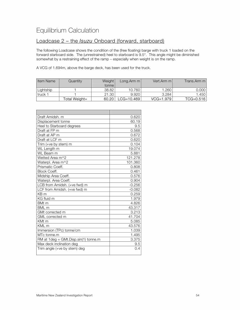
Maritime New Zealand Investigation Report 54
Equilibrium Calculation
Loadcase 2 – the Isuzu Onboard (forward, starboard) The following Loadcase shows the condition of the (free floating) barge with truck 1 loaded on the forward starboard side. The (unrestrained) heel to starboard is 9.5°. This angle might be diminished somewhat by a restraining effect of the ramp – especially when weight is on the ramp. A VCG of 1.694m, above the barge deck, has been used for the truck. Item Name Quantity Weight
tonneLong.Arm m Vert.Arm m Trans.Arm m
Lightship 1 38.82 10.760 1.260 0.000truck 1 1 21.30 9.920 3.284 1.450 Total Weight= 60.20 LCG=10.469 VCG=1.979 TCG=0.516
Draft Amidsh. m 0.620Displacement tonne 60.19Heel to Starboard degrees 9.5Draft at FP m 0.568Draft at AP m 0.672Draft at LCF m 0.620Trim (+ve by stern) m 0.104WL Length m 19.074WL Beam m 5.881Wetted Area m^2 121.278Waterpl. Area m^2 101.360Prismatic Coeff. 0.808Block Coeff. 0.461Midship Area Coeff. 0.576Waterpl. Area Coeff. 0.904LCB from Amidsh. (+ve fwd) m -0.256LCF from Amidsh. (+ve fwd) m -0.082KB m 0.259KG fluid m 1.979BMt m 4.826BML m 43.317GMt corrected m 3.213GML corrected m 41.704KMt m 5.085KML m 43.576Immersion (TPc) tonne/cm 1.039MTc tonne.m 1.495RM at 1deg = GMt.Disp.sin(1) tonne.m 3.375Max deck inclination deg 9.5Trim angle (+ve by stern) deg 0.4

Maritime New Zealand Investigation Report 55
Stability Calculation
Loadcase 2 – Isuzu Onboard (fwd., Stbd.) Maritime Rule 40C compliance criteria
-0.6
-0.4
-0.2
0
0.2
0.4
0.6
0.8
0 10 20 30 40 50
Max GZ = 0.402 m at 23 deg.
C.1.3.1.4 Initial GMt GM at 0.0 deg = 3.019 m
Heel to Starboard deg.
GZ
m
m
Heel to Starboard degrees 0.0 5.0 10.0 15.0 20.0 25.0Displacement tonne 60.19 60.20 60.20 60.19 60.20 60.20Draft at FP m 0.576 0.573 0.567 0.544 0.479 0.386Draft at AP m 0.679 0.677 0.671 0.658 0.608 0.542WL Length m 17.606 18.409 19.139 19.774 20.248 20.648Immersed Depth m 0.672 0.920 1.158 1.379 1.556 1.708WL Beam m 5.800 5.822 5.889 5.504 4.649 3.762Wetted Area m^2 121.620 121.442 121.268 113.599 106.361 106.351Waterpl. Area m^2 100.580 100.708 101.476 92.591 81.513 67.704Prismatic Coeff. 0.867 0.832 0.806 0.790 0.780 0.774Block Coeff. 0.856 0.595 0.450 0.391 0.401 0.443LCB from Amidsh. (+ve fwd) m -0.257 -0.257 -0.256 -0.257 -0.258 -0.261VCB from DWL m -0.307 -0.321 -0.366 -0.432 -0.487 -0.539GZ m -0.516 -0.249 0.026 0.274 0.386 0.396LCF from Amidsh. (+ve fwd) m -0.104 -0.090 -0.085 -0.173 -0.129 -0.069TCF to zero pt. m 0.000 0.096 0.187 0.578 0.979 1.067Max deck inclination deg 0.4 5.0 10.0 15.0 20.0 25.0Trim angle (+ve by stern) deg 0.4 0.4 0.4 0.4 0.4 0.5

Maritime New Zealand Investigation Report 56
Heel to Starboard degrees 30.0 35.0 40.0 45.0 50.0Displacement tonne 60.20 60.20 60.20 60.20 60.19Draft at FP m 0.281 0.162 0.026 -0.131 -0.320Draft at AP m 0.470 0.391 0.303 0.201 0.080WL Length m 21.030 21.229 21.389 21.452 21.453Immersed Depth m 1.847 1.972 2.083 2.178 2.257WL Beam m 3.180 2.772 2.474 2.249 2.076Wetted Area m^2 107.048 107.814 108.486 109.071 109.569Waterpl. Area m^2 57.731 50.482 45.102 41.003 37.848Prismatic Coeff. 0.766 0.764 0.761 0.762 0.764Block Coeff. 0.475 0.506 0.533 0.559 0.584LCB from Amidsh. (+ve fwd) m -0.263 -0.266 -0.269 -0.271 -0.273VCB from DWL m -0.596 -0.654 -0.711 -0.766 -0.817GZ m 0.337 0.244 0.130 0.005 -0.127LCF from Amidsh. (+ve fwd) m -0.035 -0.005 0.008 0.008 0.007TCF to zero pt. m 1.113 1.142 1.159 1.166 1.164Max deck inclination deg 30.0 35.0 40.0 45.0 50.0Trim angle (+ve by stern) deg 0.6 0.8 0.9 1.1 1.4
Code Criteria Value Units Actual Status 40C Area 0 to 30 angle of vanishing stability 45.2 deg shall not be less than (>=) 3.150 m.deg 3.858 Pass Area 0 to 40 shall not be less than (>=) 5.160 m.deg 6.264 Pass Area 30 to 40 shall not be less than (>=) 1.720 m.deg 2.406 Pass Max GZ at 30 or greater shall not be less than (>=) 0.200 m 0.337 Pass angle at which this GZ occurs deg Angle of maximum GZ shall not be less than (>=) 25.0 deg 23.0 Fail by margin,
see next table below
Initial GMt shall not be less than (>=) 0.350 m 3.019 Pass
Code Criteria Value Units Actual Status 40C Area under +ve curve to GZmx Fail angle of equilibrium (with heel arm) 9.5 deg 9.5 to the lesser of angle of first GZ peak 23.0 deg 23.0 shall be greater than (>) 3.954 m.deg 3.684 Fail Area under GZ curve. m.deg 3.684

Maritime New Zealand Investigation Report 57
Loadcase 2 – Isuzu Onboard (fwd., Stbd) MOT86 Compliance Criteria
-0.6
-0.5
-0.4
-0.3
-0.2
-0.1
0
0.1
0.2
0.3
0.4
0.5
0 10 20 30 40 50
Max GZ = 0.402 m at 23 deg.
Heel to Starboard deg.
GZ
m
.
Code Criteria Value Units Actual Status MOT86 Area under +ve curve from the greater of angle of equilibrium 9.5 deg 9.5 to the lesser of angle of vanishing stability 45.2 deg 45.2 shall not be less than (>=) 4.584 m.deg 9.088 Pass
In relation to Loadcase 2 using GZ = GM sin we have GZ = 3.213 sin 9.5° = 0.53 m. Multiplying this righting arm by the displacement gives a righting moment due to buoyancy of 31.9 tonne metres. This is the reserve capacity of the barge loaded with truck 1 to be able to right itself under the influence of any further overturning moment such as that which would be imposed by truck 2.

Maritime New Zealand Investigation Report 58
Stability Calculation
Loadcase 3 - Two Trucks Onboard (Stbd. Fwd & aft cntrline) In this case the weight of truck 2 has been split between the barge and the ramp. By taking moments about the truck LCG the truck weight is distributed with 11.33 tonnes on the front wheels and 20.17 tonnes on the rear wheels. Further assuming a 60/40 split between rear axles 3 & 4 due a lack of vertical alignment of the ramp, the effective weight of Truck 2 (on axles 1,2, & 3) = 11.33 t + 12.102 t = 23.43 tonne. Item Name Quantity Weight tonne Long.Arm m Vert.Arm m Trans.Arm mLightship 1 38.82 10.760 1.260 0.000ford truck 1 21.31 9.920 3.284 1.450aft truck 1 23.43 0.922 3.517 0.000 Total Weight= 83.71 LCG=7.791 VCG=2.411 TCG=0.371
Draft Amidsh. m -0.811 Displacement tonne 83.71 Heel to Starboard degrees 175.4 Draft at FP m -1.495 Draft at AP m -0.126 Draft at LCF m -0.859 Trim (+ve by stern) m 1.369 WL Length m 19.044 WL Beam m 5.819 Wetted Area m^2 153.868 Waterpl. Area m^2 96.611 Prismatic Coeff. 0.546 Block Coeff. 0.450 Midship Area Coeff. 0.904 Waterpl. Area Coeff. 0.872 LCB from Amidsh. (+ve fwd) m -2.818 LCF from Amidsh. (+ve fwd) m 0.591 KB m -0.197 KG fluid m 2.411 BMt m 3.165 BML m 28.142 GMt corrected m 4.477 GML corrected m 29.454 KMt m 2.968 KML m 27.945 Immersion (TPc) tonne/cm 0.990 MTc tonne.m 1.469 RM at 1deg = GMt.Disp.sin(1) tonne.m 6.541 Max deck inclination deg 173.4 Trim angle (+ve by stern) deg 4.7

Maritime New Zealand Investigation Report 59
Item Name Quantity Weight tonne Long.Arm m Vert.Arm m Trans.Arm mLightship 1 38.82 10.760 1.260 0.000ford truck 1 21.31 9.920 3.284 1.450aft truck 1 23.43 0.922 3.517 0.000 Total Weight= 83.71 LCG=7.791 VCG=2.411 TCG=0.371
T
-1
-0.9
-0.8
-0.7
-0.6
-0.5
-0.4
-0.3
-0.2
0 10 20 30 40 50
Max GZ = -0.181 m at 12.5 deg.
Heel to Starboard deg.
GZ
m
.
The analysis is showing that the barge is unstable once the weight of the second truck has been transferred onto its deck. This is due to the combination of trim and heel and the fact that there is no supporting water plane under the swim end at the stern of the barge. The ‘righting lever’ is shown as negative i.e. it has become an ‘overturning lever’ and is approximately equal to 16.7 tonne metres at a heel angle of a little less than 10°.
Heel to Starboard degrees 0.0 5.0 10.0 15.0 20.0 25.0Displacement tonne 83.71 83.71 83.71 83.71 83.71 83.71Draft at FP m 0.038 0.024 -0.054 -0.204 -0.419 -0.689Draft at AP m 1.551 1.571 1.654 1.804 2.015 2.281WL Length m 16.627 18.631 19.175 19.338 19.091 18.751Immersed Depth m 1.455 1.720 2.026 2.370 2.741 3.122WL Beam m 5.800 5.822 5.889 6.005 4.649 3.762Wetted Area m^2 141.02
3141.68
2142.571 143.545 144.343 144.917
Waterpl. Area m^2 95.227 91.839 82.108 70.895 60.650 52.333Prismatic Coeff. 0.593 0.529 0.519 0.516 0.520 0.524Block Coeff. 0.582 0.438 0.357 0.297 0.336 0.371LCB from Amidsh. (+ve fwd) m -3.090 -3.090 -3.102 -3.128 -3.161 -3.198VCB from DWL m -0.496 -0.516 -0.574 -0.667 -0.782 -0.911GZ m -0.371 -0.257 -0.189 -0.189 -0.246 -0.341LCF from Amidsh. (+ve fwd) m -0.547 -0.460 -0.418 -0.358 -0.296 -0.239TCF to zero pt. m 0.000 0.006 0.068 0.142 0.217 0.292Max deck inclination deg 5.1 7.2 11.5 16.4 21.4 26.5Trim angle (+ve by stern) deg 5.1 5.3 5.8 6.8 8.2 10.0
Heel to Starboard degrees 30.0 35.0 40.0 45.0 50.0

Maritime New Zealand Investigation Report 60
Displacement tonne 83.71 83.70 83.70 83.70 83.72Draft at FP m -1.008 -1.381 -1.808 -2.304 -2.887Draft at AP m 2.596 2.962 3.383 3.874 4.452WL Length m 18.427 18.145 17.918 17.737 17.602Immersed Depth m 3.500 3.864 4.204 4.513 4.784WL Beam m 3.180 2.965 2.917 2.830 2.655Wetted Area m^2 145.311 145.574 145.769 145.891 146.022Waterpl. Area m^2 45.835 40.775 36.833 33.776 31.230Prismatic Coeff. 0.529 0.532 0.535 0.537 0.539Block Coeff. 0.398 0.420 0.438 0.454 0.467LCB from Amidsh. (+ve fwd) m -3.235 -3.268 -3.294 -3.312 -3.320VCB from DWL m -1.044 -1.176 -1.301 -1.418 -1.523GZ m -0.455 -0.579 -0.703 -0.824 -0.940LCF from Amidsh. (+ve fwd) m -0.191 -0.150 -0.121 -0.088 -0.084TCF to zero pt. m 0.364 0.432 0.494 0.553 0.602Max deck inclination deg 31.6 36.7 41.8 46.8 51.8Trim angle (+ve by stern) deg 12.1 14.5 17.2 20.2 23.6
Code Criteria Value Units Actual Status MOT Area under +ve curve shall not be less than (>=) 4.584 m.deg Cannot be analysed as it
fails by large margin

Maritime New Zealand Investigation Report 61
Limiting KG Curves The following KG curves show the limiting values for the resultant KG of the barge and cargo allowed for various sets of criteria. Such curves could be used as a guide for safe loading, provided that the criteria had been accepted by the relevant authority. As an example the resultant KG for a barge with a lightship weight of 38.82 tonnes at a VCG of 1.26m above the base line, combined with a deck cargo of 21.31 tonnes with a VCG of 1.53 m above the deck (i.e. 3.13 m above the base line) would be:- .....KG = ((38.82 x 1.26) + (21.31 x 3.13)) / (38.82 + 21.31) = 1.92 m The resultant displacement in this case is 60.13 tonnes. Provided that the KG value is below the curve for the given displacement then the loading condition is acceptable.
Unloaded Mac III Barge Maritime Rule Part 40C Criteria A.749(18) Ch3 - Design criteria applicable to all ships 3.1.2.1: Area 0 to 30 A.749(18) Ch3 - Design criteria applicable to all ships 3.1.2.1: Area 0 to 40 A.749(18) Ch3 - Design criteria applicable to all ships 3.1.2.1: Area 30 to 40 A.749(18) Ch3 - Design criteria applicable to all ships 3.1.2.2: Max GZ at 30 or greater A.749(18) Ch3 - Design criteria applicable to all ships 3.1.2.3: Angle of maximum GZ A.749(18) Ch3 - Design criteria applicable to all ships 3.1.2.4: Initial GMt
0.75
0.775
0.8
0.825
0.85
0.875
0.9
0.925
35 40 45 50 55 60 65 70 75 80Displacement tonne
KG m
The allowable KG limit on this curve is conservatively restricted by the ‘max GZ at 30deg requirement’.

Maritime New Zealand Investigation Report 62
Unloaded Mac III Barge Maritime Rule Part 40C Criteria, 'excluding Max GZ of 0.2m at 30deg or greater', keep angle at max GZ @ 25deg. A.749(18) Ch3 - Design criteria applicable to all ships 3.1.2.1: Area 0 to 30 A.749(18) Ch3 - Design criteria applicable to all ships 3.1.2.1: Area 0 to 40 A.749(18) Ch3 - Design criteria applicable to all ships 3.1.2.1: Area 30 to 40 A.749(18) Ch3 - Design criteria applicable to all ships 3.1.2.3: Angle of maximum GZ A.749(18) Ch3 - Design criteria applicable to all ships 3.1.2.4: Initial GMt
1.3
1.35
1.4
1.45
1.5
1.55
1.6
1.65
1.7
1.75
1.8
1.85
35 40 45 50 55 60 65 70 75 80Displacement tonne
KG m

Maritime New Zealand Investigation Report 63
Unloaded Mac III Barge Maritime Rule Part 40C Criteria reduced angle of max GZ to 15°, and exclude max GZ 0.2m A.749(18) Ch3 - Design criteria applicable to all ships 3.1.2.1: Area 0 to 30 A.749(18) Ch3 - Design criteria applicable to all ships 3.1.2.1: Area 0 to 40 A.749(18) Ch3 - Design criteria applicable to all ships 3.1.2.1: Area 30 to 40 A.749(18) Ch3 - Design criteria applicable to all ships 3.1.2.3: Angle of maximum GZ A.749(18) Ch3 - Design criteria applicable to all ships 3.1.2.4: Initial GMt
2.6
2.7
2.8
2.9
3
3.1
3.2
35 40 45 50 55 60 65 70 75 80Displacement tonne
KG m

Maritime New Zealand Investigation Report 64
Unloaded Mac III Barge MOT86 Criteria Design criteria applicable ships with CB > 0.9
• Area 0 to Vanishing Angle not less than 4.584mdeg • Angle of Vanishing Angle not less than 30 deg
3.5
3.75
4
4.25
4.5
4.75
5
5.25
5.5
35 40 45 50 55 60 65 70 75Displacement tonne
KG m
The information contained in this report is subject to SGS M&I standard terms and conditions. Observations and measurements reflect the situation at the time of survey, and are subject to access and equipment limitations. Further information or specific calculations may be provided as requested.

Maritime New Zealand Investigation Report 65
Stability Calculation
Loadcase 4 - two trucks onboard (final loading position) MOT86 criteria, heeling to starboard side
Item Name
Quantity Weight tonne Long.Arm m Vert.Arm m Trans.Arm m
Lightship 1 38.82 10.760 1.260 0.000truck 1 stbd 1 21.31 10.445 3.284 1.450truck 2 port 1 31.50 11.467 3.517 -1.450 Total Weight= 91.78 LCG=10.938 VCG=2.508 TCG=-0.160
-0.1
0
0.1
0.2
0.3
0.4
0 5 10 15 20 25 30 35 40
Max GZ = 0.493 m at 18.5 deg.
Heel to Starboard deg.
GZ
m
.
Heel to Starboard degrees 0.0 5.0 10.0 15.0 20.0 25.0Displacement tonne 91.78 91.78 91.78 91.78 91.78 91.78Draft at FP m 0.981 0.980 0.976 0.976 1.012 1.062Draft at AP m 0.867 0.866 0.861 0.853 0.858 0.860WL Length m 18.805 19.540 20.216 20.844 21.324 21.451Immersed Depth m 0.974 1.222 1.458 1.686 1.934 2.176WL Beam m 5.800 5.822 5.889 5.768 4.649 3.762Wetted Area m^2 138.267 137.97
2137.99
5142.631 149.299 151.113
Waterpl. Area m^2 106.644 106.550
107.307
102.280 84.713 68.607
Prismatic Coeff. 0.852 0.821 0.796 0.778 0.768 0.769Block Coeff. 0.843 0.644 0.516 0.442 0.467 0.510LCB from Amidsh. (+ve fwd) m 0.236 0.237 0.237 0.238 0.242 0.247VCB from DWL m -0.447 -0.456 -0.484 -0.533 -0.624 -0.727GZ m 0.160 0.263 0.369 0.470 0.488 0.405LCF from Amidsh. (+ve fwd) m 0.099 0.122 0.113 0.001 0.017 0.009TCF to zero pt. m 0.001 0.110 0.222 0.162 0.046 0.124Max deck inclination deg 0.4 5.0 10.0 15.0 20.0 25.0Trim angle (+ve by stern) deg -0.4 -0.4 -0.4 -0.4 -0.5 -0.7
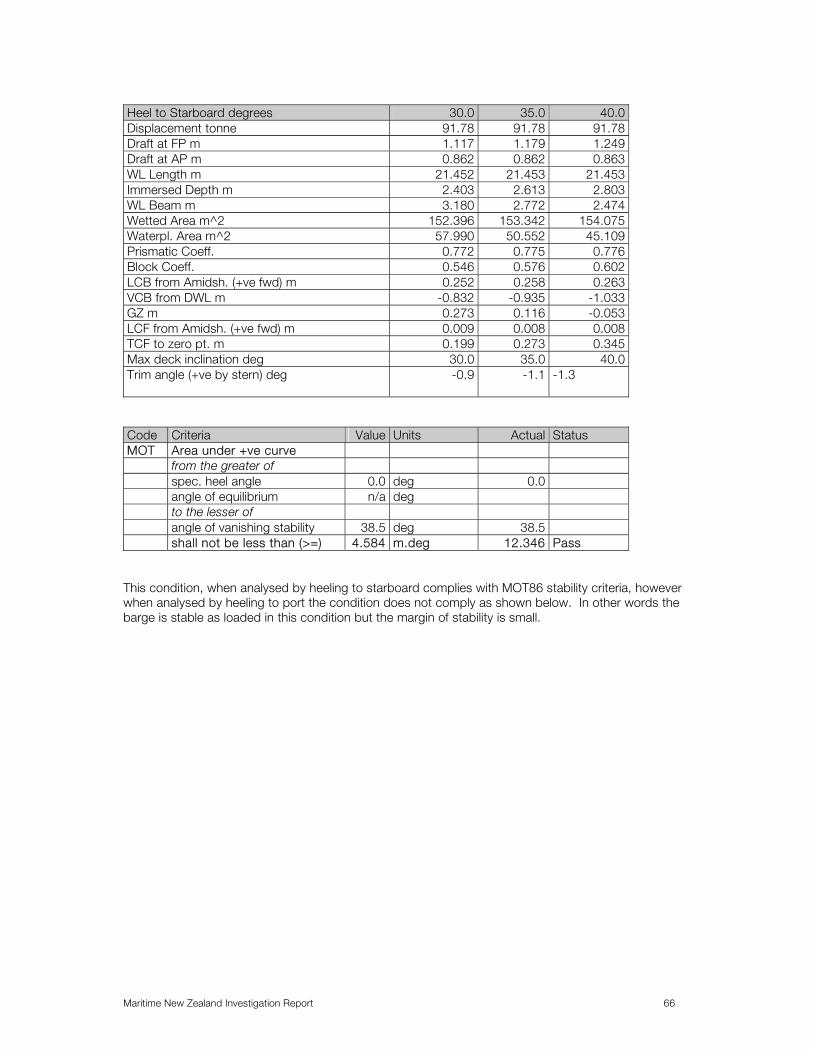
Maritime New Zealand Investigation Report 66
Heel to Starboard degrees 30.0 35.0 40.0 Displacement tonne 91.78 91.78 91.78 Draft at FP m 1.117 1.179 1.249 Draft at AP m 0.862 0.862 0.863 WL Length m 21.452 21.453 21.453 Immersed Depth m 2.403 2.613 2.803 WL Beam m 3.180 2.772 2.474 Wetted Area m^2 152.396 153.342 154.075 Waterpl. Area m^2 57.990 50.552 45.109 Prismatic Coeff. 0.772 0.775 0.776 Block Coeff. 0.546 0.576 0.602 LCB from Amidsh. (+ve fwd) m 0.252 0.258 0.263 VCB from DWL m -0.832 -0.935 -1.033 GZ m 0.273 0.116 -0.053 LCF from Amidsh. (+ve fwd) m 0.009 0.008 0.008 TCF to zero pt. m 0.199 0.273 0.345 Max deck inclination deg 30.0 35.0 40.0 Trim angle (+ve by stern) deg -0.9 -1.1 -1.3
Code Criteria Value Units Actual Status MOT Area under +ve curve from the greater of spec. heel angle 0.0 deg 0.0 angle of equilibrium n/a deg to the lesser of angle of vanishing stability 38.5 deg 38.5 shall not be less than (>=) 4.584 m.deg 12.346 Pass
This condition, when analysed by heeling to starboard complies with MOT86 stability criteria, however when analysed by heeling to port the condition does not comply as shown below. In other words the barge is stable as loaded in this condition but the margin of stability is small.

Maritime New Zealand Investigation Report 67
Stability Calculation
Loadcase 4 - two trucks onboard (final loading position) MOT86 criteria, heeling to port side Item Name Quantity Weight tonne Long.Arm m Vert.Arm m Trans.Arm mLightship 1 38.82 10.760 1.260 0.000truck 1 stbd 1 21.31 10.445 3.284 1.450truck 2 port 1 31.50 11.467 3.517 -1.450 Total Weight= 91.78 LCG=10.938 VCG=2.508 TCG=-0.160
-0.3
-0.25
-0.2
-0.15
-0.1
-0.05
0
0.05
0.1
0.15
0.2
0 5 10 15 20 25 30 35 40
Max GZ = 0.19 m at 19 deg.
Heel to Port deg.
GZ
m
.
Heel to Port degrees 0.0 5.0 10.0 15.0 20.0 25.0Displacement tonne 91.78 91.78 91.78 91.78 91.78 91.78Draft at FP m 0.981 0.980 0.977 0.976 1.012 1.061Draft at AP m 0.867 0.866 0.861 0.854 0.858 0.861WL Length m 18.805 19.552 20.223 20.848 21.326 21.451Immersed Depth m 0.974 1.222 1.458 1.686 1.934 2.176WL Beam m 5.800 5.822 5.889 5.764 4.649 3.762Wetted Area m^2 138.267 137.985 138.011 142.689 149.373 151.191Waterpl. Area m^2 106.644 106.541 107.304 102.237 84.687 68.585Prismatic Coeff. 0.852 0.820 0.796 0.778 0.768 0.769Block Coeff. 0.843 0.644 0.515 0.442 0.467 0.510LCB from Amidsh. (+ve fwd) m 0.236 0.236 0.237 0.237 0.241 0.245VCB from DWL m -0.447 -0.456 -0.484 -0.533 -0.624 -0.727GZ m -0.160 -0.056 0.053 0.161 0.186 0.115LCF from Amidsh. (+ve fwd) m 0.099 0.120 0.112 0.002 0.018 0.010TCF to zero pt. m 0.001 -0.109 -0.222 -0.161 -0.045 -0.122Max deck inclination deg 0.4 5.0 10.0 15.0 20.0 25.0Trim angle (+ve by stern) deg -0.4 -0.4 -0.4 -0.4 -0.5 -0.7

Maritime New Zealand Investigation Report 68
Heel to Port degrees 30.0 35.0 40.0Displacement tonne 91.78 91.78 91.78Draft at FP m 1.116 1.177 1.247Draft at AP m 0.864 0.865 0.867WL Length m 21.452 21.452 21.453Immersed Depth m 2.403 2.612 2.801WL Beam m 3.180 2.772 2.474Wetted Area m^2 152.473 153.420 154.153Waterpl. Area m^2 57.972 50.536 45.095Prismatic Coeff. 0.773 0.775 0.777Block Coeff. 0.546 0.576 0.602LCB from Amidsh. (+ve fwd) m 0.250 0.254 0.258VCB from DWL m -0.832 -0.935 -1.033GZ m -0.005 -0.146 -0.299LCF from Amidsh. (+ve fwd) m 0.010 0.009 0.009TCF to zero pt. m -0.198 -0.272 -0.344Max deck inclination deg 30.0 35.0 40.0Trim angle (+ve by stern) deg -0.9 -1.1 -1.3
Code Criteria Value Units Actual Status MOT Area under +ve curve Fail from the greater of spec. heel angle 0.0 deg angle of equilibrium 7.6 deg 7.6 to the lesser of spec. heel angle 40.0 deg angle of vanishing stability 29.8 deg 29.8 shall not be less than (>=) 4.584 m.deg 2.595 Fail

Maritime New Zealand Investigation Report 69
Equilibrium Calculation - Mac III
Loadcase 5 - Three trucks (inc. pump truck) onboard This Loadcase shows the three trucks in the final loaded condition, and has assumed a 9 tonne weight for the pump truck. Item Name Quantity Weight tonne Long.Arm m Vert.Arm m Trans.Arm mLightship 1 38.82 10.760 1.260 0.000truck 1 stbd 1 21.31 9.220 3.284 1.450truck 2 port 1 31.50 10.545 3.517 -1.400truck 3 1 9.000 3.250 3.350 0.000 Total Weight= 100.9 LCG=9.700 VCG=2.584 TCG=-0.129
Draft Amidsh. m 0.996 Displacement tonne 100.9 Heel to Starboard degrees -8.1 Draft at FP m 0.706 Draft at AP m 1.286 Draft at LCF m 1.009 Trim (+ve by stern) m 0.580 WL Length m 20.249 WL Beam m 5.858 Wetted Area m^2 144.406 Waterpl. Area m^2 106.578 Prismatic Coeff. 0.686 Block Coeff. 0.504 Midship Area Coeff. 0.809 Waterpl. Area Coeff. 0.898 LCB from Amidsh. (+ve fwd) m -1.085 LCF from Amidsh. (+ve fwd) m -0.382 KB m 0.510 KG fluid m 2.584 BMt m 2.880 BML m 30.865 GMt corrected m 0.845 GML corrected m 28.829 KMt m 3.390 KML m 31.375 Immersion (TPc) tonne/cm 1.093 MTc tonne.m 1.732 RM at 1deg = GMt.Disp.sin(1) tonne.m 1.487 Max deck inclination deg 8.4 Trim angle (+ve by stern) deg 2.0

Maritime New Zealand Investigation Report 70
Stability Calculation
Loadcase 5 - Three trucks (inc. pump truck) onboard MOT86 Compliance Criteria
-0.7
-0.6
-0.5
-0.4
-0.3
-0.2
-0.1
0
0.1
0.2
0.3
0.4
0 10 20 30 40 50
Max GZ = 0.305 m at 14.5 deg.
Heel to Starboard deg.
GZ
m.
Heel to Starboard degrees 0.0 5.0 10.0 15.0 20.0 25.0Displacement tonne 100.8 100.9 100.9 100.9 100.9 100.9Draft at FP m 0.713 0.709 0.698 0.668 0.626 0.567Draft at AP m 1.285 1.285 1.295 1.358 1.479 1.644WL Length m 19.180 19.906 20.363 20.631 20.859 21.050Immersed Depth m 1.248 1.496 1.741 2.021 2.331 2.653WL Beam m 5.800 5.822 5.889 6.004 4.649 3.762Wetted Area m^2 142.849 142.699 147.252 155.931 161.640 164.309Waterpl. Area m^2 107.984 108.113 103.505 92.799 78.848 66.917Prismatic Coeff. 0.723 0.697 0.684 0.679 0.668 0.656Block Coeff. 0.708 0.567 0.471 0.393 0.435 0.468LCB from Amidsh. (+ve fwd) m -1.084 -1.085 -1.088 -1.100 -1.116 -1.138VCB from DWL m -0.495 -0.503 -0.531 -0.597 -0.698 -0.817GZ m 0.129 0.207 0.279 0.305 0.262 0.159LCF from Amidsh. (+ve fwd) m -0.514 -0.520 -0.173 0.274 0.222 0.096TCF to zero pt. m 0.001 0.116 0.108 -0.042 -0.128 -0.118Max deck inclination deg 2.0 5.4 10.2 15.2 20.2 25.2Trim angle (+ve by stern) deg 2.0 2.0 2.0 2.4 2.9 3.7

Maritime New Zealand Investigation Report 71
Heel to Starboard degrees 30.0 35.0 40.0 45.0 50.0Displacement tonne 100.8 100.8 100.9 100.9 100.9Draft at FP m 0.490 0.398 0.291 0.165 0.016Draft at AP m 1.842 2.073 2.337 2.644 3.009WL Length m 21.214 21.364 21.507 21.567 21.590Immersed Depth m 2.971 3.274 3.555 3.809 4.034WL Beam m 3.180 2.772 2.474 2.249 2.076Wetted Area m^2 165.631 166.473 167.194 167.793 168.297Waterpl. Area m^2 57.746 50.621 45.202 41.088 37.912Prismatic Coeff. 0.647 0.640 0.635 0.632 0.630Block Coeff. 0.491 0.507 0.520 0.533 0.544LCB from Amidsh. (+ve fwd) m -1.165 -1.191 -1.214 -1.234 -1.250VCB from DWL m -0.940 -1.061 -1.178 -1.286 -1.386GZ m 0.021 -0.135 -0.300 -0.469 -0.637LCF from Amidsh. (+ve fwd) m 0.022 0.013 0.024 0.030 0.037TCF to zero pt. m -0.061 0.022 0.111 0.198 0.284Max deck inclination deg 30.2 35.3 40.3 45.3 50.3Trim angle (+ve by stern) deg 4.6 5.7 7.0 8.4 10.1
Code Criteria Value Units Actual Status MOT Area under +ve curve from the greater of spec. heel angle 0.0 deg 0.0 to the lesser of angle of vanishing stability 30.7 deg 30.7 shall not be less than (>=) 4.584 m.deg 6.538 Pass
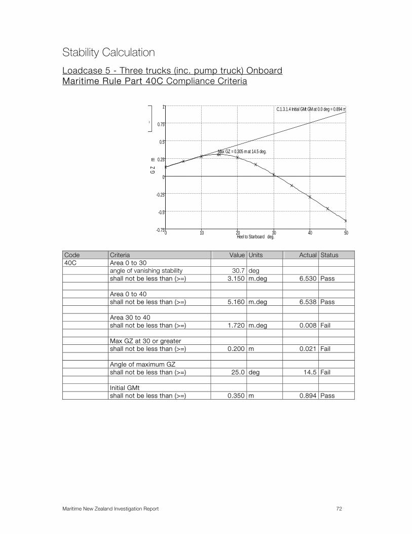
Maritime New Zealand Investigation Report 72
Stability Calculation
Loadcase 5 - Three trucks (inc. pump truck) Onboard Maritime Rule Part 40C Compliance Criteria
-0.75
-0.5
-0.25
0
0.25
0.5
0.75
1
0 10 20 30 40 50
Max GZ = 0.305 m at 14.5 deg.
C.1.3.1.4 Initial GMt GM at 0.0 deg = 0.894 m
Heel to Starboard deg.
GZ
m
m
Code Criteria Value Units Actual Status 40C Area 0 to 30 angle of vanishing stability 30.7 deg shall not be less than (>=) 3.150 m.deg 6.530 Pass Area 0 to 40 shall not be less than (>=) 5.160 m.deg 6.538 Pass Area 30 to 40 shall not be less than (>=) 1.720 m.deg 0.008 Fail Max GZ at 30 or greater shall not be less than (>=) 0.200 m 0.021 Fail Angle of maximum GZ shall not be less than (>=) 25.0 deg 14.5 Fail Initial GMt shall not be less than (>=) 0.350 m 0.894 Pass
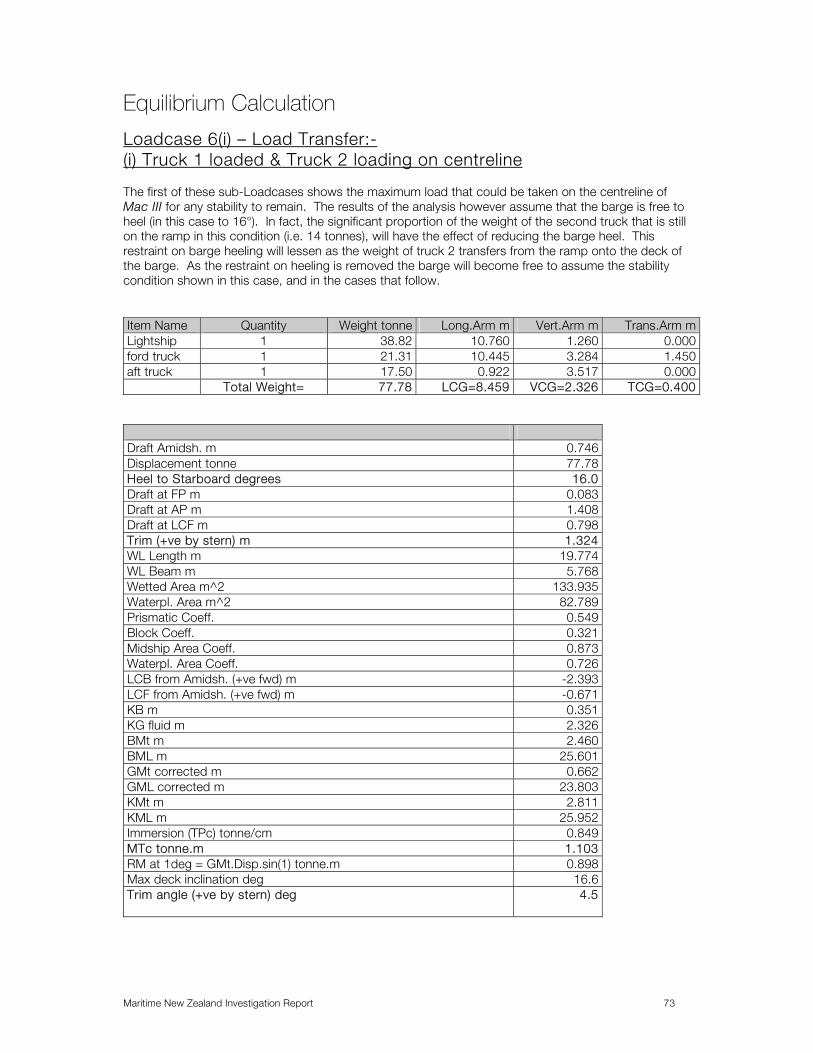
Maritime New Zealand Investigation Report 73
Equilibrium Calculation
Loadcase 6(i) – Load Transfer:- (i) Truck 1 loaded & Truck 2 loading on centreline The first of these sub-Loadcases shows the maximum load that could be taken on the centreline of Mac III for any stability to remain. The results of the analysis however assume that the barge is free to heel (in this case to 16°). In fact, the significant proportion of the weight of the second truck that is still on the ramp in this condition (i.e. 14 tonnes), will have the effect of reducing the barge heel. This restraint on barge heeling will lessen as the weight of truck 2 transfers from the ramp onto the deck of the barge. As the restraint on heeling is removed the barge will become free to assume the stability condition shown in this case, and in the cases that follow. Item Name Quantity Weight tonne Long.Arm m Vert.Arm m Trans.Arm mLightship 1 38.82 10.760 1.260 0.000ford truck 1 21.31 10.445 3.284 1.450aft truck 1 17.50 0.922 3.517 0.000 Total Weight= 77.78 LCG=8.459 VCG=2.326 TCG=0.400
Draft Amidsh. m 0.746 Displacement tonne 77.78 Heel to Starboard degrees 16.0 Draft at FP m 0.083 Draft at AP m 1.408 Draft at LCF m 0.798 Trim (+ve by stern) m 1.324 WL Length m 19.774 WL Beam m 5.768 Wetted Area m^2 133.935 Waterpl. Area m^2 82.789 Prismatic Coeff. 0.549 Block Coeff. 0.321 Midship Area Coeff. 0.873 Waterpl. Area Coeff. 0.726 LCB from Amidsh. (+ve fwd) m -2.393 LCF from Amidsh. (+ve fwd) m -0.671 KB m 0.351 KG fluid m 2.326 BMt m 2.460 BML m 25.601 GMt corrected m 0.662 GML corrected m 23.803 KMt m 2.811 KML m 25.952 Immersion (TPc) tonne/cm 0.849 MTc tonne.m 1.103 RM at 1deg = GMt.Disp.sin(1) tonne.m 0.898 Max deck inclination deg 16.6 Trim angle (+ve by stern) deg 4.5

Maritime New Zealand Investigation Report 74
Loadcase 6(i) Stability Calculation
-0.45
-0.4
-0.35
-0.3
-0.25
-0.2
-0.15
-0.1
-0.05
0
0.05
0 5 10 15 20 25 30 35 40
Max GZ = 0.001 m at 17 deg.
Heel to Starboard deg.
GZ
m
.
Heel to Starboard degrees 0.0 5.0 10.0 15.0 20.0 25.0Displacement tonne 77.78 77.78 77.79 77.78 77.77 77.78Draft at FP m 0.222 0.218 0.195 0.109 -0.040 -0.238Draft at AP m 1.304 1.304 1.320 1.387 1.507 1.669GZ m -0.400 -0.238 -0.088 -0.007 -0.010 -0.074LCF from Amidsh. (+ve fwd) m -0.996 -0.995 -0.794 -0.685 -0.621 -0.577TCF to zero pt. m 0.000 0.098 0.161 0.240 0.321 0.396Trim angle (+ve by stern) deg 3.7 3.7 3.8 4.4 5.3 6.5
Heel to Starboard degrees 30.0 35.0 40.0Displacement tonne 77.77 77.77 77.77Draft at FP m -0.473 -0.745 -1.059Draft at AP m 1.861 2.083 2.337GZ m -0.173 -0.290 -0.417LCF from Amidsh. (+ve fwd) m -0.537 -0.470 -0.422TCF to zero pt. m 0.467 0.545 0.610Trim angle (+ve by stern) deg 7.9 9.6 11.4
Code Criteria Value Units Actual Status Area under +ve curve Fail from the greater of angle of equilibrium 16.3 deg 16.3 to the lesser of angle of vanishing stability 18.1 deg 18.1 shall not be less than (>=) 4.584 m.deg 0.001 Fail

Maritime New Zealand Investigation Report 75
Stability Calculation
Loadcase 6(ii) – Load Transfer:- (i) Truck 1 loaded & Truck 2 loading 250mm to Port of Centreline Item Name Quantity Weight tonne Long.Arm m Vert.Arm m Trans.Arm mLightship 1 38.82 10.760 1.260 0.000ford truck 1 21.31 10.445 3.284 1.450aft truck 1 17.50 0.922 3.517 -0.250 Total Weight= 77.78 LCG=8.459 VCG=2.326 TCG=0.343
This condition shows truck two loading 250mm to port of the barge centreline. With an angle of heel of 11.5° a small margin of stability remains. Given that 14 tonnes of the weight of the second is still on the ramp in this condition, the angle of heel would be significantly less than the free floating equilibrium value of 11.5°, and consequently, the margin of stability would be greater than shown in the GZ curve below. In this condition the longitudinal centre of gravity of truck two is 922mm forward of the stern of the barge. This is a possible configuration for the loading of the second truck with the third axle just coming onto the barge.
-0.7
-0.6
-0.5
-0.4
-0.3
-0.2
-0.1
0
0.1
0 10 20 30 40 50
Max GZ = 0.056 m at 17 deg.
Heel to Starboard deg.
GZ
m
.
Heel to Starboard degrees 0.0 5.0 10.0 15.0 20.0 25.0Displacement tonne 77.78 77.78 77.79 77.78 77.77 77.78Draft at FP m 0.217 0.213 0.189 0.103 -0.048 -0.248Draft at AP m 1.309 1.309 1.325 1.393 1.515 1.679WL Beam m 5.800 5.822 5.889 6.005 4.649 3.762Waterpl. Area m^2 103.916 104.00
397.303 85.337 73.024 62.713
Block Coeff. 0.573 0.458 0.381 0.318 0.355 0.385GZ m -0.343 -0.181 -0.032 0.048 0.044 -0.023LCF from Amidsh. (+ve fwd) m -0.996 -0.995 -0.793 -0.684 -0.620 -0.578Trim angle (+ve by stern) deg 3.7 3.7 3.8 4.4 5.3 6.5

Maritime New Zealand Investigation Report 76
Heel to Starboard degrees 30.0 35.0 40.0 45.0 50.0 Displacement tonne 77.77 77.77 77.77 77.77 77.78 WL Beam m 3.180 2.994 2.903 2.752 2.637 Waterpl. Area m^2 54.643 48.210 43.281 39.477 36.507 Block Coeff. 0.407 0.424 0.437 0.449 0.460 GZ m -0.124 -0.244 -0.375 -0.508 -0.641 Trim angle (+ve by stern) deg 7.9 9.6 11.5 13.6 16.1
Code Criteria Value Units Actual Status Area under curve Very Small angle of equilibrium 11.5 deg 11.5 angle of vanishing stability 23.6 deg 23.6 shall not be less than (>=) 4.584 m.deg 0.445 Fail

Maritime New Zealand Investigation Report 77
Stability Calculation
Loadcase 6(iii) – Load Transfer:- (i) Truck 1 loaded & Truck 2 Loading with Full Weight to Port of Centreline These cases show that there is a degree of stability in the free floating condition provided that once the full weight of truck two is on board, the centre of gravity is more than 800mm to the port of the centreline of the barge. Firstly, with the centre of gravity 2.222m from the stern of the barge and 800mm to port of the centreline there is no stability in the free floating condition. Item Name Quantity Weight tonne Long.Arm m Vert.Arm m Trans.Arm mLightship 1 38.82 10.760 1.260 0.000ford truck 1 21.31 10.445 3.284 1.450aft truck 1 31.50 2.222 3.517 -0.800 Total Weight= 91.78 LCG=7.756 VCG=2.508 TCG=0.064
-1.2
-1
-0.8
-0.6
-0.4
-0.2
0
0 10 20 30 40 50
Max GZ = -0.001 m at 8 deg.
Heel to Starboard deg.
GZ
m
.
Heel to Starboard degrees 0.0 5.0 10.0 15.0 20.0 25.0Displacement tonne 91.79 91.78 91.78 91.79 91.78 91.78WL Length m 14.276 16.415 17.163 17.192 16.896 16.514Immersed Depth m 1.590 1.958 2.313 2.729 3.196 3.692WL Beam m 5.800 5.821 5.889 5.959 4.649 3.762Waterpl. Area m^2 82.055 78.869 69.662 59.371 50.003 42.427Block Coeff. 0.680 0.479 0.383 0.320 0.357 0.390GZ m -0.063 -0.012 -0.005 -0.059 -0.162 -0.294Trim angle (+ve by stern) deg 6.2 6.4 7.2 8.7 10.7 13.3
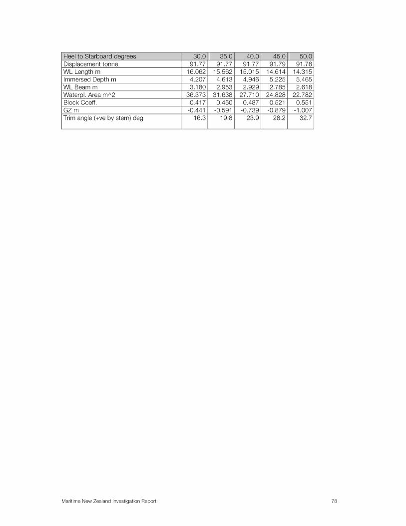
Maritime New Zealand Investigation Report 78
Heel to Starboard degrees 30.0 35.0 40.0 45.0 50.0 Displacement tonne 91.77 91.77 91.77 91.79 91.78 WL Length m 16.062 15.562 15.015 14.614 14.315 Immersed Depth m 4.207 4.613 4.946 5.225 5.465 WL Beam m 3.180 2.953 2.929 2.785 2.618 Waterpl. Area m^2 36.373 31.638 27.710 24.828 22.782 Block Coeff. 0.417 0.450 0.487 0.521 0.551 GZ m -0.441 -0.591 -0.739 -0.879 -1.007 Trim angle (+ve by stern) deg 16.3 19.8 23.9 28.2 32.7
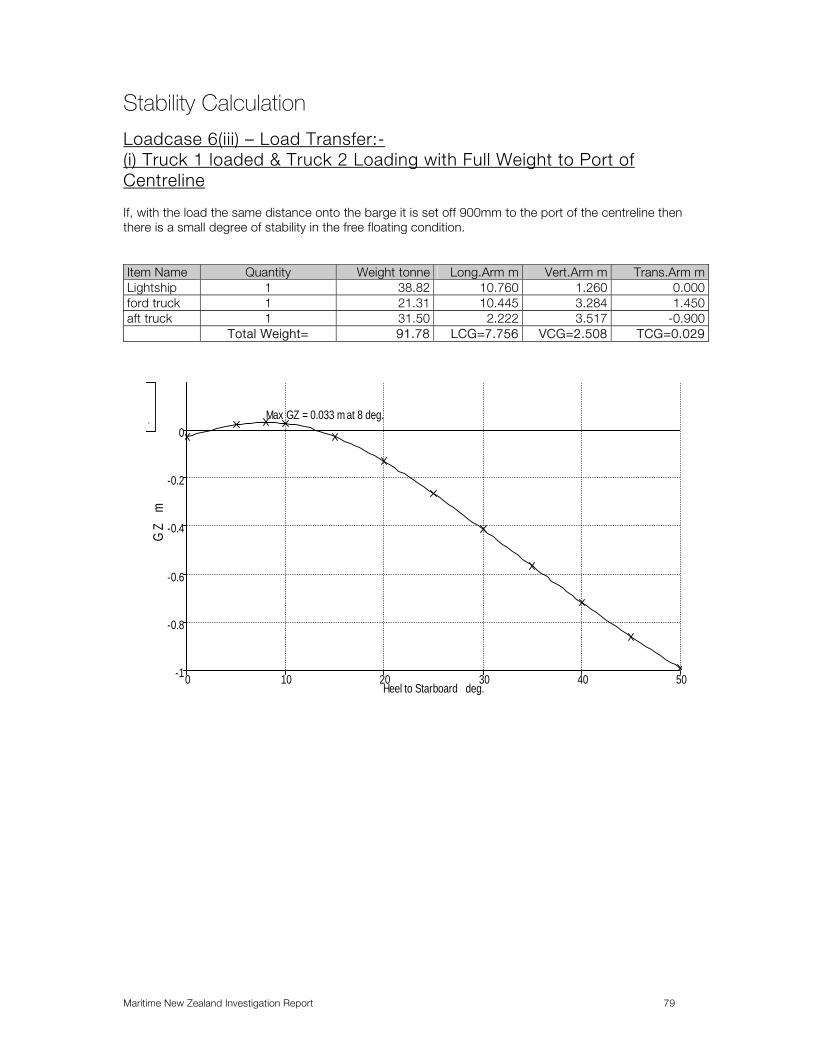
Maritime New Zealand Investigation Report 79
Stability Calculation
Loadcase 6(iii) – Load Transfer:- (i) Truck 1 loaded & Truck 2 Loading with Full Weight to Port of Centreline If, with the load the same distance onto the barge it is set off 900mm to the port of the centreline then there is a small degree of stability in the free floating condition. Item Name Quantity Weight tonne Long.Arm m Vert.Arm m Trans.Arm mLightship 1 38.82 10.760 1.260 0.000ford truck 1 21.31 10.445 3.284 1.450aft truck 1 31.50 2.222 3.517 -0.900 Total Weight= 91.78 LCG=7.756 VCG=2.508 TCG=0.029
-1
-0.8
-0.6
-0.4
-0.2
0
0 10 20 30 40 50
Max GZ = 0.033 m at 8 deg.
Heel to Starboard deg.
GZ
m
.

Maritime New Zealand Investigation Report 80
Heel to Starboard degrees 0.0 5.0 10.0 15.0 20.0 25.0Displacement tonne 91.79 91.78 91.78 91.79 91.78 91.78WL Length m 14.276 16.414 17.159 17.184 16.883 16.493WL Beam m 5.800 5.821 5.889 5.959 4.649 3.762Waterpl. Area m^2 82.055 78.856 69.633 59.324 49.932 42.324Block Coeff. 0.680 0.479 0.383 0.320 0.357 0.390GZ m -0.029 0.023 0.028 -0.027 -0.131 -0.265Trim angle (+ve by stern) deg 6.2 6.4 7.2 8.7 10.7 13.3
Heel to Starboard degrees 30.0 35.0 40.0 45.0 50.0 Displacement tonne 91.77 91.78 91.77 91.79 91.79 WL Length m 16.020 15.474 14.921 14.485 14.088 WL Beam m 3.180 2.946 2.917 2.807 2.618 Waterpl. Area m^2 36.228 31.387 27.461 24.496 22.282 Block Coeff. 0.417 0.452 0.490 0.526 0.560 GZ m -0.413 -0.566 -0.717 -0.860 -0.991 Trim angle (+ve by stern) deg 16.4 20.0 24.1 28.6 33.2
Code Criteria Value Units Actual Status angle of
equilibrium 2.3 deg 2.3
angle of vanishing stability
13.2 deg 13.2
MOT86 shall not be less than (>=)
4.584 m.deg 0.234 Fail

Maritime New Zealand Investigation Report 81
Stability Calculation
Loadcase 6(iii) – Load Transfer:- (i) Truck 1 loaded & Truck 2 Loading with Full Weight to Port of Centreline With the load the same distance onto the barge and set further off 1200mm to the port of the centreline then the degree of stability in the free floating condition increases. Item Name Quantity Weight tonne Long.Arm m Vert.Arm m Trans.Arm mLightship 1 38.82 10.760 1.260 0.000ford truck 1 21.31 10.445 3.284 1.450aft truck 1 31.50 2.222 3.517 -1.200 Total Weight= 91.78 LCG=7.756 VCG=2.508 TCG=-0.074
-1
-0.8
-0.6
-0.4
-0.2
0
0 10 20 30 40 50
Max GZ = 0.134 m at 8 deg.
Heel to Starboard deg.
GZ
m
.
Heel to Starboard degrees 0.0 5.0 10.0 15.0 20.0 25.0Displacement tonne 91.79 91.78 91.78 91.78 91.78 91.77WL Length m 14.276 16.408 17.145 17.149 16.842 16.429WL Beam m 5.800 5.821 5.889 5.960 4.649 3.762Waterpl. Area m^2 82.055 78.819 69.547 59.116 49.716 42.011Block Coeff. 0.680 0.479 0.383 0.320 0.356 0.390GZ m 0.074 0.125 0.129 0.071 -0.037 -0.175Trim angle (+ve by stern) deg 6.2 6.4 7.2 8.7 10.8 13.4

Maritime New Zealand Investigation Report 82
Heel to Starboard degrees 30.0 35.0 40.0 45.0 50.0 Displacement tonne 91.77 91.79 91.78 91.78 91.79 WL Length m 15.889 15.252 14.591 13.853 13.223 WL Beam m 3.180 2.943 2.874 2.803 2.723 Waterpl. Area m^2 35.770 30.743 26.570 23.258 20.702 Block Coeff. 0.417 0.458 0.502 0.550 0.597 GZ m -0.330 -0.492 -0.653 -0.806 -0.947 Trim angle (+ve by stern) deg 16.6 20.4 24.9 29.9 35.2
Code Criteria Value Units Actual Status angle of vanishing stability 18.5 deg 18.5 MOT86 shall not be less than (>=) 4.584 m.deg 1.830 Fail

Maritime New Zealand Investigation Report 83
Equilibrium Calculation
Loadcase 7(i) - Two trucks (Heel to Stbd) Item Name Quantity Weight
tonneLong.Arm m Vert.Arm m Trans.Arm m
Lightship 1 38.82 10.760 1.260 0.000truck 1 stbd 1 18.00 11.545 3.284 1.450truck 2 port 1 20.50 11.467 3.517 -1.450truck 3 0 9.000 10.725 0.865 0.000 Total Weight= 77.47 LCG=11.140 VCG=2.331 TCG=-0.045
Draft Amidsh. m 0.796 Displacement tonne 77.46 Heel to Starboard degrees -1.5 Draft at FP m 0.899 Draft at AP m 0.693 Draft at LCF m 0.798 Trim (+ve by stern) m -0.206 WL Length m 18.259 WL Beam m 5.802 Wetted Area m^2 130.674 Waterpl. Area m^2 103.915 Prismatic Coeff. 0.820 Block Coeff. 0.743 Midship Area Coeff. 0.919 Waterpl. Area Coeff. 0.981 LCB from Amidsh. (+ve fwd) m 0.447 LCF from Amidsh. (+ve fwd) m 0.173 KB m 0.411 KG fluid m 2.331 BMt m 3.734 BML m 37.057 GMt corrected m 1.815 GML corrected m 35.138 KMt m 4.145 KML m 37.468 Immersion (TPc) tonne/cm 1.065 MTc tonne.m 1.621 RM at 1deg = GMt.Disp.sin(1) tonne.m 2.454 Max deck inclination deg 1.6 Trim angle (+ve by stern) deg -0.7

Maritime New Zealand Investigation Report 84
Stability Calculation
Loadcase 7(i) - Two trucks (Heel to Stbd)
-0.8
-0.4
0
0.4
0.8
1.2
1.6
2
0 10 20 30 40 50
Max GZ = 0.64 m at 21.5 deg.
Initial GMt GM at 0.0 deg = 1.787 m
Heel to Starboard deg.
GZ
m
m
Heel to Starboard degrees
0.0 5.0 10.0 15.0 20.0 25.0
Displacement tonne 77.47 77.47 77.47 77.46 77.47 77.47 Draft at FP m 0.899 0.898 0.894 0.887 0.876 0.862 Draft at AP m 0.693 0.691 0.685 0.675 0.631 0.560 WL Length m 18.034 18.756 19.419 20.028 20.551 20.968 WL Beam m 5.800 5.822 5.889 6.005 5.058 4.094 Waterpl. Area m^2 102.833 102.831 103.672 103.927 90.039 74.013 Block Coeff. 0.815 0.610 0.482 0.394 0.404 0.442 GZ m 0.045 0.201 0.361 0.529 0.634 0.612 Trim angle (+ve by stern) deg
-0.7 -0.7 -0.7 -0.7 -0.8 -1.0
Heel to Starboard degrees
30.0 35.0 40.0 45.0 50.0 55.0
Displacement tonne 77.47 77.48 77.47 77.47 77.47 77.47 Draft at FP m 0.850 0.839 0.828 0.816 0.802 0.785 Draft at AP m 0.477 0.381 0.270 0.141 -0.012 -0.202 WL Length m 21.142 21.310 21.457 21.459 21.460 21.462 WL Beam m 3.460 3.016 2.691 2.447 2.258 2.112 Waterpl. Area m^2 62.905 54.973 49.084 44.619 41.185 38.513 Block Coeff. 0.477 0.505 0.529 0.554 0.576 0.597 GZ m 0.518 0.386 0.234 0.069 -0.103 -0.279 Trim angle (+ve by stern) deg
-1.3 -1.6 -1.9 -2.3 -2.8 -3.4

Maritime New Zealand Investigation Report 85
Code Criteria Value Units Actual Status Appendix 1 Area 0 to 30 Pass Maritime Rule Part 40C
from the greater of
spec. heel angle 0.0 deg 0.0 to the lesser of spec. heel angle 30.0 deg 30.0 angle of vanishing stability 47.0 deg shall not be less than (>=) 3.150 m.deg 13.208 Pass Appendix 1 Area 0 to 40 Pass spec. heel angle 40.0 deg 40.0 angle of vanishing stability 47.0 deg shall not be less than (>=) 5.160 m.deg 17.037 Pass Appendix 1 Area 30 to 40 Pass spec. heel angle 30.0 deg 30.0 to the lesser of spec. heel angle 40.0 deg 40.0 angle of vanishing stability 47.0 deg shall not be less than (>=) 1.720 m.deg 3.828 Pass Appendix 1 Angle of maximum GZ Fail* shall not be less than (>=) 25.0 deg 21.5 Fail* Appendix 1 Initial GMt Pass spec. heel angle 0.0 deg shall not be less than (>=) 0.350 m 1.787 Pass
* Acceptable under the provisions of Maritime Rule Part 40C, Appendix 1 (2) (f) (iv). Code Criteria Value Units Actual Status MOT86 Pass from the greater of spec. heel angle 0.0 deg 0.0 angle of equilibrium n/a deg to the lesser of angle of max. GZ 21.5 deg 21.5 shall not be less than (>=) 4.584 m.deg 7.520 Pass

Maritime New Zealand Investigation Report 86
Stability Calculation
Loadcase 7(i) - Two trucks (Heel to Port)
-0.5
-0.4
-0.3
-0.2
-0.1
0
0.1
0.2
0.3
0.4
0.5
0.6
0 10 20 30 40 50
Max GZ = 0.526 m at 21.5 deg.
Heel to Port deg.
GZ
m
.
Code Criteria Value Units Actual Status Appendix 1 MOT86 Pass from the
greater of
spec. heel angle
0.0 deg
angle of equilibrium
1.4 deg 1.4
to the lesser of angle of max.
GZ 21.5 deg 21.5
shall not be less than (>=)
4.584 m.deg 5.828 Pass

Maritime New Zealand Investigation Report 87
Stability Calculation
Loadcase 7(ii) - Three trucks onboard (Stbd Heel) The following Loadcase shows the stability condition with three trucks of 18 tonnes, 20.5 tonnes, and 9 tonnes loaded forward starboard, forward port and aft centreline. Item Name Quantity Weight tonne Long.Arm m Vert.Arm m Trans.Arm mLightship 1 38.82 10.760 1.260 0.000truck 1 stbd 1 18.00 11.545 3.284 1.450truck 2 port 1 20.50 11.567 3.517 -1.450truck 3 1 9.000 3.658 3.350 0.000 Total Weight= 86.55 LCG=10.380 VCG=2.438 TCG=-0.040
-0.8
-0.4
0
0.4
0.8
1.2
0 10 20 30 40 50
Max GZ = 0.509 m at 21 deg.
Initial GMt GM at 0.0 deg = 1.378 m
Heel to Starboard deg.
GZ
m
m
Heel to Starboard degrees
0.0 5.0 10.0 15.0 20.0 25.0
Displacement tonne 86.54 86.55 86.54 86.55 86.55 86.55 Draft at FP m 0.792 0.789 0.783 0.776 0.749 0.705 Draft at AP m 0.973 0.972 0.969 0.962 0.967 0.981 Immersed Depth m 0.961 1.210 1.446 1.668 1.888 2.099 WL Beam m 5.800 5.822 5.889 6.005 5.058 4.094 Block Coeff. 0.825 0.629 0.503 0.415 0.424 0.464 GZ m 0.040 0.161 0.284 0.416 0.507 0.467 Trim angle (+ve by stern) deg
0.6 0.6 0.6 0.6 0.7 0.9

Maritime New Zealand Investigation Report 88
Heel to Starboard degrees
30.0 35.0 40.0 45.0 50.0 55.0
WL Beam m 3.460 3.016 2.691 2.447 2.258 2.112 Waterpl. Area m^2 63.087 55.007 49.084 44.619 41.185 38.513 Block Coeff. 0.497 0.527 0.554 0.578 0.600 0.620 GZ m 0.363 0.225 0.070 -0.096 -0.267 -0.440 Trim angle (+ve by stern) deg
1.2 1.5 1.8 2.2 2.6 3.1
Code Criteria Value Units Actual Status Appendix 1 MOT86 Pass angle of max. GZ 21.0 deg 21.0 shall not be less than (>=) 4.584 m.deg 6.219 Pass
Code Criteria Value Units Actual Status Appendix 1 Area 0 to 30 Pass Maritime Rule Part 40C
spec. heel angle 30.0 deg 30.0
angle of vanishing stability 42.1 deg shall not be less than (>=) 3.150 m.deg 10.284 Pass Appendix 1 Area 0 to 40 Pass spec. heel angle 40.0 deg 40.0 angle of vanishing stability 42.1 deg shall not be less than (>=) 5.160 m.deg 12.508 Pass Appendix 1 Area 30 to 40 Pass spec. heel angle 30.0 deg 30.0 to the lesser of spec. heel angle 40.0 deg 40.0 angle of vanishing stability 42.1 deg shall not be less than (>=) 1.720 m.deg 2.224 Pass Appendix 1 Max GZ at 30 or greater Not AnalysedAppendix 1 Angle of maximum GZ Fail* shall not be less than (>=) 25.0 deg 21.0 Fail* Appendix 1 Initial GMt Pass shall not be less than (>=) 0.350 m 1.378 Pass
* Acceptable under the provision of Part 40C, Appendix 1 (2) (f) (iv).

Maritime New Zealand Investigation Report 89
Equilibrium Calculation
Loadcase 7(ii) - Three trucks onboard (Stbd Heel) Item Name Quantity Weight tonne Long.Arm m Vert.Arm m Trans.Arm mLightship 1 38.82 10.760 1.260 0.000truck 1 stbd 1 18.00 11.545 3.284 1.450truck 2 port 1 20.50 11.567 3.517 -1.450truck 3 1 9.000 3.658 3.350 0.000 Total Weight= 86.55 LCG=10.380 VCG=2.438 TCG=-0.040
Draft Amidsh. m 0.882Displacement tonne 86.54Heel to Starboard degrees -1.7Draft at FP m 0.791Draft at AP m 0.973Draft at LCF m 0.883Trim (+ve by stern) m 0.182WL Length m 18.601WL Beam m 5.802Wetted Area m^2 133.598Waterpl. Area m^2 103.761Prismatic Coeff. 0.826Block Coeff. 0.747Midship Area Coeff. 0.914Waterpl. Area Coeff. 0.961LCB from Amidsh. (+ve fwd) m -0.355LCF from Amidsh. (+ve fwd) m -0.158KB m 0.455KG fluid m 2.438BMt m 3.356BML m 33.003GMt corrected m 1.376GML corrected m 31.022KMt m 3.812KML m 33.458Immersion (TPc) tonne/cm 1.064MTc tonne.m 1.599RM at 1deg = GMt.Disp.sin(1) tonne.m 2.078Max deck inclination deg 1.8Trim angle (+ve by stern) deg 0.6

Maritime New Zealand Investigation Report 90
Stability Calculation
Loadcase 7(ii) - Three trucks onboard (Port Heel) Item Name Quantity Weight tonne Long.Arm m Vert.Arm m Trans.Arm mLightship 1 38.82 10.760 1.260 0.000truck 1 stbd 1 18.00 11.545 3.284 1.450truck 2 port 1 20.50 11.567 3.517 -1.450truck 3 1 9.000 3.658 3.350 0.000 Total Weight= 86.55 LCG=10.380 VCG=2.438 TCG=-0.040
-0.8
-0.6
-0.4
-0.2
0
0.2
0.4
0.6
0 10 20 30 40 50
Max GZ = 0.433 m at 21 deg.
Heel to Port deg.
GZ
m
.
Heel to Port degrees
0.0 5.0 10.0 15.0 20.0 25.0
Displacement tonne 86.54 86.55 86.54 86.55 86.55 86.55 Draft at FP m 0.792 0.789 0.783 0.776 0.749 0.706 Draft at AP m 0.973 0.972 0.969 0.962 0.967 0.981 WL Length m 18.351 19.063 19.708 20.302 20.860 21.171 Immersed Depth m 0.961 1.210 1.446 1.668 1.888 2.099 WL Beam m 5.800 5.822 5.889 6.005 5.058 4.093 Waterpl. Area m^2 104.427 104.315 105.146 106.711 91.151 74.410 Block Coeff. 0.825 0.629 0.503 0.415 0.424 0.464 GZ m -0.040 0.080 0.204 0.338 0.430 0.394 Trim angle (+ve by stern) deg
0.6 0.6 0.6 0.6 0.7 0.9
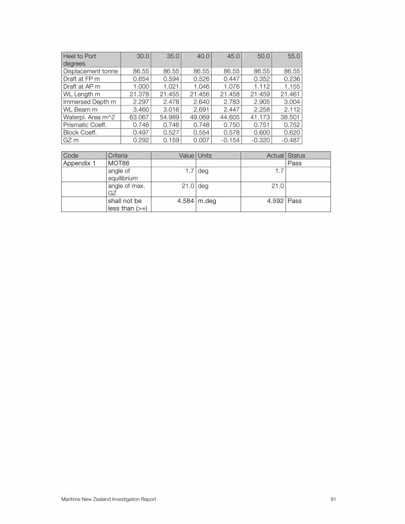
Maritime New Zealand Investigation Report 91
Heel to Port degrees
30.0 35.0 40.0 45.0 50.0 55.0
Displacement tonne 86.55 86.55 86.55 86.55 86.55 86.55 Draft at FP m 0.654 0.594 0.526 0.447 0.352 0.236 Draft at AP m 1.000 1.021 1.046 1.076 1.112 1.155 WL Length m 21.378 21.455 21.456 21.458 21.459 21.461 Immersed Depth m 2.297 2.478 2.640 2.783 2.905 3.004 WL Beam m 3.460 3.016 2.691 2.447 2.258 2.112 Waterpl. Area m^2 63.067 54.989 49.069 44.605 41.173 38.501 Prismatic Coeff. 0.746 0.746 0.748 0.750 0.751 0.752 Block Coeff. 0.497 0.527 0.554 0.578 0.600 0.620 GZ m 0.292 0.159 0.007 -0.154 -0.320 -0.487
Code Criteria Value Units Actual Status Appendix 1 MOT86 Pass angle of
equilibrium 1.7 deg 1.7
angle of max. GZ
21.0 deg 21.0
shall not be less than (>=)
4.584 m.deg 4.592 Pass

Maritime New Zealand Investigation Report 92
APPENDIX 2
Mac III Dumb Barge Loading Ramp Condition Report 24 August 2005 A survey of the loading ramp of the dumb barge Mac III was conducted at McManaway’s premises on 24 August 2005. The general condition of the ramp at the time is shown in Plate 1.
Plate 1. Mac III Loading Ramp The ramp was 3.6 m wide and 6.5 m long. The construction was of 100mm by 150mm Douglas fir and Pine timber bearers laid transversely with 200 centre to centre spacings over steel substructure. The steel work consisted of two pairs of longitudinal ‘I’ section girders tied in the middle with a single transverse ‘C’ section girder and at the shore end with a box section beam. The general arrangement of the substructure is shown in Plate 2.
Plate 2. Ramp Steel Substructure

Maritime New Zealand Investigation Report 93
Measurements taken at the time indicated that the longitudinal ‘I’ beams have 230mm by 6mm webs and 150mm by 8mm flanges, top and bottom, giving an inertia of 4 * 107 mm4 for each beam. The transverse ‘C’ section beam has a 230mm by 6mm web and 90mm by 8mm flanges. The close ended, box section at the shore end of the ramp was 100mm by 100mm, of undetermined thickness. At the barge the two pairs of longitudinal girders were pinned port and starboard at 2.2m spacing with 540mm long, 1 ¾ “ diameter pins taken from a discarded propeller shaft and therefore most likely to be of 316 grade stainless steel (Plate 3).
Plate 3. Ramp Pinned Connection to Barge When measured (at 1407 hrs) the height from these pins to the water surface was 1.22m, and the unloaded barge had a draft of 465mm. Steel bollards on the ramp were secured with chain at the shore end (Plate 4).
Plate 4. Ramp to Shore Arrangement.

Maritime New Zealand Investigation Report 94
Visual inspection of the steel substructure and barge connections did not reveal any cracks in the welds and the steel timber fastenings were in fair condition. The steel was poorly protected in way of coating and rusting corrosion was widely evident. The level of corrosion was however within reasonable limits of serviceability. (i.e. diminution levels were not excessive). The timber bearers were generally sound with no obvious evidence of rot or worm etc. There were cracks in some of the transverse timbers. Longitudinal timber bearers had been positioned on the ramp in way of the loading path in order to distribute the load over the transverse timbers. One notable area of mechanically induced damage was at the top of the ramp at the starboard side of the ramp where two of the timbers had been broken in way of their cantilevered extension outboard of the longitudinal supporting beams (Plate 5).
Plate 5. Broken Timber at Top of Ramp. The information contained in this report is subject to SGS M&I standard terms and conditions. Observations and measurements reflect the situation at the time of survey, and are subject to access and equipment limitations. Further digital photographs, taken at the time, and information or specific calculations may be provided as requested.

Maritime New Zealand Investigation Report 95
APPENDIX 3
Commercial Launchmaster Certificate Syllabus
Nautical 1. Magnetic Compass 1.1 Uses sight vane, shadow pin or azimuth mirror to take compass bearings.
1.2 Uses model or steering simulator to steer a course by compass.
1.3 Finds the magnetic variation, to the nearest degree, using the compass rose on the chart.
1.4 Knows that course alterations affect the value of the deviation.
1.5 Describes the effect of heeling error and its change with alteration of course.
1.6 Knows that a compass declaration and table of deviations are drawn up by a compass adjuster to indicate the deviations for every 10° of the ship's head.
1.7 Applies variation to convert true directions to magnetic and vice versa.
1.8 Understands the general causes of deviation and gives examples of items of equipment on board that are likely to affect the deviation and knows the Importance of siting them at a safe distance from the compass.
2. Charts 2.1 Locates a position on the chart using the latitude and longitude scales.
2.2 Fixes the vessel's position on the chart given magnetic bearings and/or radar ranges and quotes the latitude and longitude obtained.
2.3 Obtain a lat/long readout from GPS equipment and correctly plot the position on a chart
2.4 Finds the dead reckoning position at a future time given the magnetic course steered and the log speed.
2.5 Finds the magnetic course to steer and the ETA at a given destination given the starting position and the log speed.
2.6 Understand why it is important to check the vessel’s position regularly and the action to take if found off track.
2.7 Identify transits and clearing marks from the chart in order to plan safe approaches to harbours and anchorages.
2.8 States the meaning and explains the significance of the chart symbols and abbreviations in common use.
2.9 Knows how to obtain and use weekly editions of Notices to Mariners in order to correct charts.
3. Buoys and Beacons 3.1 Recognise the buoys and beacons of IALA System "A" by day or night and describe the
appropriate action to take on encountering them.

Maritime New Zealand Investigation Report 96
4. Tides 4.1 Finds the times of high and low water at any New Zealand port.
4.2 Determines the approximate dates of spring and neap tides.
4.3 Find the predicted set and rate of the tide from tidal reference points on the chart, tidal arrows on the chart, and tide tables for Tory Channel and French Pass.
5. International Regulations for the Prevention of Collisions at Sea 5.1 Recognise the lights, day shapes and fog signals for all classes of vessels.
5.2 Recognise the manoeuvring sound signals and know when to use them.
5.3 Recognise a developing collision situation by compass, radar or visual reference.
5.4 States the correct action to take, by day or night, to avoid collision in any case using models or projected images.
5.5 Describes the precautions to take in poor visibility with regard to:
(a) Speed (b) Fog signals (c) Lookout (d) Radar (e) Navigation lights (f) Echo sounder (g) Auto pilot
5.6 Assess the likelihood of collision and determine the appropriate action to take in poor visibility
when:
(a) a vessel is detected by radar alone (b) the fog signal is heard but the vessel is beyond the visible range
6. Distress Signals and Communications 6.1 States the conditions under which distress signals may be used and knows that there is an
obligation to render assistance.
6.2 Describes and recognise all the distress signals and state the action to be taken on seeing or hearing any of them.
6.3 Demonstrate and understand the correct use of pyrotechnics and EPIRBS describing the appropriate circumstances for their use.
6.4 Recognizes the following code flags and knows their meanings :
A C F G K N P U V W Z 6.5 Demonstrate the correct 'MAYDAY', 'PANPAN' and 'SECURITE' message procedures stating
the purpose of each one.
6.6. Pronounces correctly all the phonetic letters and numbers.
Maritime New Zealand Investigation Report 97
7. Lifesaving Appliances 7.1 Demonstrate the correct way to don an approved lifejacket and describes how to enter the
water and use the attachments.
7.2 Describe the fittings attached to approved lifebuoys, rigid liferafts and buoyant apparatus and knows how to use them in an emergency.
7.3 Describe the care and maintenance needed to keep lifejackets and lifebuoys in good condition.
7.4 Describes the correct way to launch an inflatable liferaft, enter it from the boat or the water, rescue survivors and care for them.
7.5 Lists the equipment carried in a coastal liferaft.
7.6 Knows the lifesaving equipment which must be carried by a 20m restricted limit ship and a 15m inshore fishing boat.
8. Firefighting 8.1 Describe the conditions necessary for combustion to occur.
8.2 Describe the correct way to attack a shipboard fire using hoses, extinguishers or fixed installations.
8.3 Describe the dangers associated with plastic materials in a shipboard fire.
8.4 Describes the precautions to take on board which will reduce the fire hazard.
8.5 Knows the fire fighting equipment which must be carried by a 20m restricted limit ship and a 15m inshore fishing boat
9. Deck Appliances and Steering Gear 9.1 Describes the safety precautions to be observed when using a winch or windlass.
9.2 Describe the correct maintenance procedures for mechanical, hand hydraulic and electric hydraulic steering gear.
9.3 Describe the means employed for emergency steering and what routine maintenance is required for the gear.
10. Ropes, Rigging, Bends and Hitches 10.1 Describes the comparative strengths, characteristics and causes of deterioration of
polypropylene, polyester, polyethylene, nylon and natural fibre ropes.
10.2 Demonstrates how to tie the following bends and hitches and knows the uses for each one:
(a) Round turn and two half hitches. (b) Clove hitch (c) Bowline (d) Sheet bend (e) Reef knot (f) Fisherman's bend

Maritime New Zealand Investigation Report 98
11. Stability 11.1 Understands what is meant by good stability and poor stability and recognises the warning
signs of the latter.
11.2 Describe the effect on stability of:
(a) Raising and lowering weights (b) Freely suspended weights (c) Free fluid surface (d) Low freeboard (e) Obstructed freeing ports.
12. Accidents 12.1 States the appropriate procedures for dealing with:
(a) Collision (b) Hull damage (c) Grounding (d) Loss of steering (e) Fouled propeller
12.2 Describes the appropriate procedures for:
(a) Rescuing crew and passengers from other vessels. (b) Beaching a vessel. (c) Recovering a man overboard. (d) Towing or being towed. (e) Anchoring in an emergency (f) Abandoning a vessel (g) Reporting accidents/incidents to the MSA.
13. Ship Handling 13.1 Describe precautions to be taken in heavy weather.
13.2 Describe the procedure for crossing a bar on which the sea is breaking.
13.3 Demonstrate, with the aid of models, methods of berthing and leaving a berth under various conditions of wind and tide.
13.4 State the features of a good anchorage.
13.5 Describe the preparations and techniques for anchoring.
13.6 Know the various ways of determining if an anchor is dragging
14. Meteorology 14.1 Interpret a weather map to predict wind direction and strength.
14.2 State the signs of an approaching cold front and know the weather associated with such a front.

Maritime New Zealand Investigation Report 99
15. Regulations 15.1 Describes the potential dangers, obligations and responsibilities contained in the current set of
Marine Notices.
15.2 Knows the requirements of the General Harbour (Nautical and Miscellaneous) Regulations and the Water Recreation Regulations insofar as they apply to restricted limit and inshore fishing vessels.
15.3 Know the appropriate safe practices for skippers when carrying passengers in small boats, with particular reference to Operating Limits in Maritime Rules Part 20, to determine the limits which apply to a particular visit.
15.4 Knows the purpose and content of relevant sections of Safe Ship Management Systems in Maritime Rules Part 21.
15.5 Knows the minimum manning requirements specified in the Shipping (Manning of Restricted Limit Ships) Regulations and the Shipping (Manning of Fishing Boats) Regulations insofar as they apply to ships skippered by Commercial Launchmasters including inshore fishing vessels.
16. Watchkeeping 16.1 Know the following recommended safe watchkeeping practices:
(a) Watchkeepers to be experienced and capable (b) Precautions to be taken against fatigue. (c) Number of watchkeepers to be increased at critical times. (d) Auto pilot to have a frequent reset alarm. (e) Radar to be used in addition to but not instead of a visual lookout. (f) The hazards associated with a "divided command".
16.2 Explains the dangers of placing undue reliance on the auto pilot.
16.2 Know the correct procedure for using radar with particular reference to:
(a) Obtaining a satisfactory display. (b) Using range rings or parallel index techniques to ensure safe passing distances off
navigational hazards. (c) Describing the effects of sea clutter and the dangers of incorrect setting of the anti clutter
control. 16.4 Describe the use of the echo sounder to maintain a safe distance off the coast, to approach
an anchorage, to cross a bar and to verify position.

Maritime New Zealand Investigation Report 100
APPENDIX 4
Graph – TCG vs List (deg)
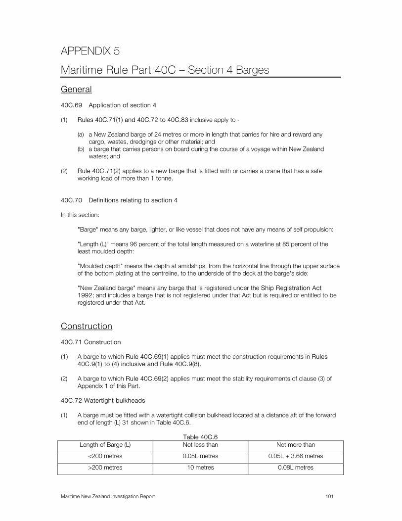
Maritime New Zealand Investigation Report 101
APPENDIX 5
Maritime Rule Part 40C – Section 4 Barges
General 40C.69 Application of section 4 (1) Rules 40C.71(1) and 40C.72 to 40C.83 inclusive apply to -
(a) a New Zealand barge of 24 metres or more in length that carries for hire and reward any cargo, wastes, dredgings or other material; and
(b) a barge that carries persons on board during the course of a voyage within New Zealand waters; and
(2) Rule 40C.71(2) applies to a new barge that is fitted with or carries a crane that has a safe
working load of more than 1 tonne. 40C.70 Definitions relating to section 4 In this section:
"Barge" means any barge, lighter, or like vessel that does not have any means of self propulsion: "Length (L)" means 96 percent of the total length measured on a waterline at 85 percent of the least moulded depth: "Moulded depth" means the depth at amidships, from the horizontal line through the upper surface of the bottom plating at the centreline, to the underside of the deck at the barge's side: "New Zealand barge" means any barge that is registered under the Ship Registration Act 1992; and includes a barge that is not registered under that Act but is required or entitled to be registered under that Act.
Construction 40C.71 Construction (1) A barge to which Rule 40C.69(1) applies must meet the construction requirements in Rules
40C.9(1) to (4) inclusive and Rule 40C.9(8). (2) A barge to which Rule 40C.69(2) applies must meet the stability requirements of clause (3) of
Appendix 1 of this Part. 40C.72 Watertight bulkheads (1) A barge must be fitted with a watertight collision bulkhead located at a distance aft of the forward
end of length (L) 31 shown in Table 40C.6.
Table 40C.6 Length of Barge (L) Not less than Not more than
<200 metres 0.05L metres 0.05L + 3.66 metres
>200 metres 10 metres 0.08L metres
Maritime New Zealand Investigation Report 102
(2) Where a chain locker is fitted abaft the collision bulkhead, it must be made watertight. 40C.73 Deck openings (1) For a barge of 24 metres or more in length, deck openings for hatches and air pipes must be
protected in accordance with the requirements of Part 47. (2) For a barge of less than 24 metres in length - (a) cargo hatches must be protected by weathertight covers and coamings of at least, - (i) if the barge is not proceeding beyond enclosed waters, 300 mm in height; and
(ii) if the barge is proceeding beyond enclosed waters, 600 mm in height; and
(b) other deck openings must be provided with coamings or doors leading to openings that have sills of a minimum height of at least, -
(i) if the barge is not proceeding beyond enclosed waters, 150 mm; and (ii) if the barge is
proceeding beyond enclosed waters, 300 mm. Barges having no distinct fore or aft end which can be towed or pushed from either end will have this bulkhead at both ends. 40C.74 Bulwarks and guard rails (1) A barge that carries any person on board during a voyage must be fitted with bulwarks or guard
rails on any deck or part of a deck to which those persons have access during the voyage. (2) Where such bulwarks or guard rails are fitted, they must meet the requirements of Rule 40C.20
and Rule 40C.21. 40C.75 Bilge system (1) A barge that does not carry any person on board during a voyage and is fitted with below deck
machinery spaces, or has fixed piping systems led through void spaces, must be provided with a means of pumping from and draining such spaces.32
(2) A barge that carries 12 persons or more on board during a voyage must be provided with bilge
pumps and a bilge system that -
(a) is capable of draining any compartment below the deck; and (b) complies with Rules 40C.24,40C.25 and 40C.26.
(3) A barge that carries less than 12 persons on board during a voyage must meet the requirements
of Rules 40C.24 and 40C.26, except that manual pumps may be substituted for the power pump requirements of Rule 40C.24.
40C.76 Air pipes (1) The following tanks, void spaces and cofferdams of barges must be fitted with air pipes:
(a) all tanks containing flammable liquids, combustible liquids or chemicals; and
32 The means maybe by use of suitable hand pumps and fixed bilge piping systems or by means of portable pumps stored
on board the barge.

Maritime New Zealand Investigation Report 103
(b) all tanks, cofferdams and voids adjacent to tanks containing flammable liquids, combustible
liquids or chemicals; and
(c) all voids through which pressure piping passes; and
(d) all tanks that are filled or emptied through fixed pumping arrangements. (2) Air pipes must -
(a) meet the requirements of Rule 47.44; and (b) be of substantial construction; and
(c) be fitted with flame screens where necessary.
40C.77 Cargo piping systems (1) Cargo piping systems for low flashpoint liquids (at or below 60 degrees C Close Cup Test) must -
(a) be independent of all other piping systems; and (b) not pass through –
(i) fuel oil tanks; or (ii) spaces containing machinery, where sources of vapour ignition are normally present.
(2) Cargo pumps must be so designed as to minimise the danger of sparking. (3) Cargo piping and other arrangements for barges intended for the carriage of dangerous
chemicals in bulk must comply with the requirements of the International Code for the Construction and Equipment of Ships Carrying Dangerous Chemicals in Bulk (IBC Code) adopted by the International Maritime Organisation by Resolution MSC.4(48).
(4) Cargo piping and other arrangements for barges intended for the carriage of liquefied gases in
bulk must comply with the requirements of the International Code for the Construction and Equipment of Ships Carrying Liquefied Gases in Bulk (IGC Code) adopted by the International Maritime Organisation by Resolution MSC.5(48).
Safety Equipment 40C.78 Fire fighting appliances (1) Machinery spaces of barges that do not carry persons on board during a voyage must be
provided with fire extinguishers -
(a) in accordance with Table 40C.7; and (b) that comply with Part 42B.
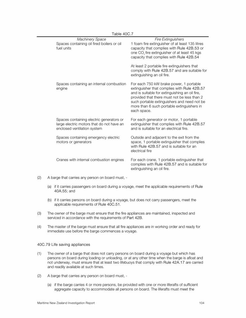
Maritime New Zealand Investigation Report 104
Table 40C.7
Machinery Space Fire Extinguishers Spaces containing oil fired boilers or oil fuel units
1 foam fire extinguisher of at least 135 litres capacity that complies with Rule 42B.53 or one CO2 fire extinguisher of at least 45 kgs capacity that complies with Rule 42B.54 At least 2 portable fire extinguishers that comply with Rule 42B.57 and are suitable for extinguishing an oil fire.
Spaces containing an internal combustion engine
For each 750 kW brake power, 1 portable extinguisher that complies with Rule 42B.57 and is suitable for extinguishing an oil fire, provided that there must not be less than 2 such portable extinguishers and need not be more than 6 such portable extinguishers in each space.
Spaces containing electric generators or large electric motors that do not have an enclosed ventilation system
For each generator or motor, 1 portable extinguisher that complies with Rule 42B.57 and is suitable for an electrical fire.
Spaces containing emergency electric motors or generators
Outside and adjacent to the exit from the space, 1 portable extinguisher that complies with Rule 42B.57 and is suitable for an electrical fire
Cranes with internal combustion engines For each crane, 1 portable extinguisher that complies with Rule 42B.57 and is suitable for extinguishing an oil fire.
(2) A barge that carries any person on board must, -
(a) if it carries passengers on board during a voyage, meet the applicable requirements of Rule 40A.55; and
(b) if it carries persons on board during a voyage, but does not carry passengers, meet the
applicable requirements of Rule 40C.51. (3) The owner of the barge must ensure that the fire appliances are maintained, inspected and
serviced in accordance with the requirements of Part 42B. (4) The master of the barge must ensure that all fire appliances are in working order and ready for
immediate use before the barge commences a voyage. 40C.79 Life saving appliances (1) The owner of a barge that does not carry persons on board during a voyage but which has
persons on board during loading or unloading, or at any other time when the barge is afloat and not underway, must ensure that at least two lifebuoys that comply with Rule 42A.17 are carried and readily available at such times.
(2) A barge that carries any person on board must, -
(a) if the barge carries 4 or more persons, be provided with one or more liferafts of sufficient aggregate capacity to accommodate all persons on board. The liferafts must meet the

Maritime New Zealand Investigation Report 105
requirements of Rules 42A.11 and 42A.12 and must be stowed so as to be readily placed in the water on either side of the barge; and
(b) be provided with at least 2 lifebuoys that comply with Rule 42A.17, one of which must be
provided with a buoyant lifeline; and (c) be provided with a lifejacket for every person on board. Lifejackets must meet the
requirements of Rule 42A.19 and must have a buoyancy of at least 71 Newtons if the barge is operating in restricted limits, and at least 100 Newtons if operating in the coastal limit. One lifejacket that complies with Rule 42A.19 and is suitable for children must be provided for each child carried; and
(d) be provided with at least 6 rocket parachute flares when proceeding beyond restricted limits,
at least 2 rocket parachute flares and 2 buoyant smoke signals when operating within inshore limits, and at least 2 buoyant smoke signals and 2 hand flares if operating in enclosed waters only. The rocket parachute flares, buoyant smoke floats and hand held flares must comply with Rules 42A.22, 42A.24 and 42A.23 respectively.
(3) The owner of the barge must ensure that the life saving appliances are maintained, inspected and
serviced in accordance with the requirements of Part 42B. (5) The owner of the barge must ensure that all life saving appliances are in working order and ready
for immediate use before the barge commences a voyage. 40C.80 Radiocommunications A barge that carries any person on board must –
(a) if it carries passengers on board during a voyage, meet the applicable requirements of Rule 40A.57; and
(b) if it carries persons on board during a voyage, but does not carry passengers, meet the
applicable requirements of Rule 40C.53.
Miscellaneous 40C.81 Crew accommodation A barge that carries persons on board during a voyage, but does not carry passengers, must meet the applicable requirements of Rules 40C.16, 40C.17 and 40C.35. 40C.82 Passengers (1) A barge that carries passengers on board during a voyage must meet the requirements of Rules
40A.12 to 40A.21 inclusive and Rules 40A.25 and 40A.42. (2) The owner of a barge must ensure that passengers are not carried on any barge that is used, has
been used or is intended to be used, for carrying oil, chemicals or liquefied gas in bulk or dangerous goods as cargo.
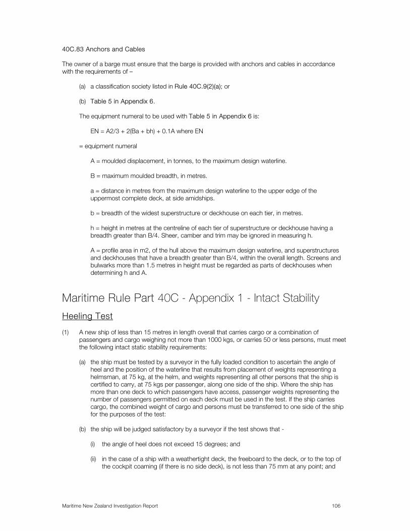
Maritime New Zealand Investigation Report 106
40C.83 Anchors and Cables The owner of a barge must ensure that the barge is provided with anchors and cables in accordance with the requirements of –
(a) a classification society listed in Rule 40C.9(2)(a); or (b) Table 5 in Appendix 6.
The equipment numeral to be used with Table 5 in Appendix 6 is:
EN = A2/3 + 2(Ba + bh) + 0.1A where EN
= equipment numeral
A = moulded displacement, in tonnes, to the maximum design waterline. B = maximum moulded breadth, in metres.
a = distance in metres from the maximum design waterline to the upper edge of the uppermost complete deck, at side amidships. b = breadth of the widest superstructure or deckhouse on each tier, in metres. h = height in metres at the centreline of each tier of superstructure or deckhouse having a breadth greater than B/4. Sheer, camber and trim may be ignored in measuring h. A = profile area in m2, of the hull above the maximum design waterline, and superstructures and deckhouses that have a breadth greater than B/4, within the overall length. Screens and bulwarks more than 1.5 metres in height must be regarded as parts of deckhouses when determining h and A.
Maritime Rule Part 40C - Appendix 1 - Intact Stability
Heeling Test (1) A new ship of less than 15 metres in length overall that carries cargo or a combination of
passengers and cargo weighing not more than 1000 kgs, or carries 50 or less persons, must meet the following intact static stability requirements:
(a) the ship must be tested by a surveyor in the fully loaded condition to ascertain the angle of
heel and the position of the waterline that results from placement of weights representing a helmsman, at 75 kg, at the helm, and weights representing all other persons that the ship is certified to carry, at 75 kgs per passenger, along one side of the ship. Where the ship has more than one deck to which passengers have access, passenger weights representing the number of passengers permitted on each deck must be used in the test. If the ship carries cargo, the combined weight of cargo and persons must be transferred to one side of the ship for the purposes of the test:
(b) the ship will be judged satisfactory by a surveyor if the test shows that -
(i) the angle of heel does not exceed 15 degrees; and (ii) in the case of a ship with a weathertight deck, the freeboard to the deck, or to the top of
the cockpit coaming (if there is no side deck), is not less than 75 mm at any point; and

Maritime New Zealand Investigation Report 107
(iii) in the case of an open boat, the freeboard to the top of the gunwale is not less than 250 mm at any point:
(c) where a cockpit is fitted, it must be demonstrated that the ship has a reserve of buoyancy and
that the ship does not heel more than 15 degrees when the cockpit is full of water.
Inclining Test and Stability Criteria (2) (a) A new ship of 15 metres or more in length overall; and
(b) a new ship that carries cargo, or a combination of passengers and cargo weighing more than 1000 kgs, or carrying more than 50 persons,
must meet the following intact stability requirements:
(c) the lightship weight, vertical centre of gravity (KG) and longitudinal centre of gravity (LCG) of the ship must be determined from the results of an inclining experiment witnessed by a surveyor:
(d) the lightship weight must be increased by a margin for growth, which must be 5 percent of the
lightship weight positioned at the lightship LCG and vertical centre of the weather deck amidships or lightship KG, whichever is the higher:
(e) curves of statical stability (GZ curves) must be produced by a surveyor recognised for that
purpose for -
(i) loaded departure with 100 percent consumables; and (ii) loaded arrival with 10 percent consumables; and (iii) anticipated service conditions; and (iv) any condition where a deck cargo is carried; and (v) conditions involving lifting appliances (if relevant):
(f) the curves of statical stability for the loaded conditions must meet the following criteria:
(i) the area under the righting lever curve (GZ curve) must not be less than 0.055 metre-
radians up to 30 degrees angle of heel and not less than 0.09 metre-radians up to 40 degrees angle of heel or the angle of downflooding, if this angle is less; and
(ii) the area under the GZ curve between the angles of heel of 30 and 40 degrees or between
30 degrees and the angle of downflooding if that angle is less than 40 degrees, must be not less than 0.03 metre-radians; and
(iii) the righting lever (GZ) must be at least 0.20 metres at an angle of heel equal to or greater
than 30 degrees; and (iv) the maximum GZ must occur at an angle of heel of not less than 25 degrees. However
where the ship has a hull form that results in the maximum GZ occurring at an angle of heel less than 25 degrees but not less than 15 degrees, this may be accepted by a surveyor if the area under the GZ curve up to the angle (m) at which the maximum GZ occurs is not less than 0.055 + 0.002(30 - m) metre-radians; and
(v) after correction for free surface effects, the initial metacentric height (GM) must not be less
than 0.35 metres.

Maritime New Zealand Investigation Report 108
Deck Cranes (3) (a) A ship, or a barge to which section 4 applies, that is fitted with a deck crane or other lifting
device, or carries a mobile crane, must be subjected to a practical test with the ship in its worst anticipated service load condition to establish the angle of heel and the minimum freeboard on the low side.
(b) Except as provided in clause (3)(c) of this Appendix, with the crane or other lifting device
operating at its maximum load moment t he angle of heel must not exceed 7 degrees or that angle of heel which results in a freeboard on the low side of 250 mm, whichever is the lesser angle.
(c) When an angle of heel greater than 7 degrees but not exceeding 10 degrees occurs, a
surveyor may accept the lifting condition if all the following criteria are satisfied when the crane or lifting device is operating at its maximum load moment:
(i) the range of stability from the angle of static equilibrium is equal to or greater than 20
degrees; and (ii) the area under the curve of residual righting lever, up to 40 degrees from the angle of
static equilibrium or the downflooding angle, if that angle is less than 40 degrees, is equal to or greater than 0.1 metre radians; and
(iii) the minimum freeboard fore and aft throughout the lifting operations is not less than half
the assigned freeboard at amidships. For ships with less than 1000 mm assigned freeboard amidships, the freeboard fore or aft must not be less than 500 mm.
Tugs (4) Ships engaged in towing must meet the requirements of clause (2) of this Appendix. In addition, for
all conditions where towing can be undertaken, the tow rope heeling lever curve must be plotted on the curve of righting levers. The tow rope heeling lever curve is determined by assuming the bollard pull athwartships at 30 degrees to the horizontal. The area of the curve of righting levers above the heeling lever curve up to 40 degrees angle of heel, or the angle of downflooding if that is less than 40 degrees, is to be calculated. The proportion of this area to the total area of the curve of righting levers from 0 ° to 40°, or the angle of downflooding if that is less than 40°, must not be less than 40 per cent.
Dredgers (5) (a) Ships engaged in dredging must meet the requirements of clause (2) of this Appendix.
(b) E>dredgers and hopper barges that operate with open hold spaces must have their stability investigated by the 'spill out'33 method or an alternative method that the owner or builder can demonstrate to the Director is at least as effective as the 'spill out' method.
(c) Except as provided in clause 5(d) of this Appendix, dredgers and hopper barges that operate
with their hold spaces closed by hatch covers or other permanent means must have the effects of free surface (suitably amended for density) taken into account when calculating the ship's stability for various conditions of loading.
33 For details of the 'spill out' method see Section 8, Sub-section C of the Australian Transport Advisory Council Uniform
Shipping Laws Code.
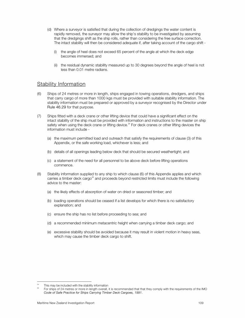
Maritime New Zealand Investigation Report 109
(d) Where a surveyor is satisfied that during the collection of dredgings the water content is rapidly removed, the surveyor may allow the ship's stability to be investigated by assuming that the dredgings shift as the ship rolls, rather than considering the free surface correction. The intact stability will then be considered adequate if, after taking account of the cargo shift -
(i) the angle of heel does not exceed 65 percent of the angle at which the deck edge
becomes immersed; and (ii) the residual dynamic stability measured up to 30 degrees beyond the angle of heel is not
less than 0.01 metre radians.
Stability Information (6) Ships of 24 metres or more in length, ships engaged in towing operations, dredgers, and ships
that carry cargo of more than 1000 kgs must be provided with suitable stability information. The stability information must be prepared or approved by a surveyor recognised by the Director under Rule 46.29 for that purpose.
(7) Ships fitted with a deck crane or other lifting device that could have a significant effect on the
intact stability of the ship must be provided with information and instructions to the master on ship safety when using the deck crane or lifting device.34 For deck cranes or other lifting devices the information must include -
(a) the maximum permitted load and outreach that satisfy the requirements of clause (3) of this
Appendix, or the safe working load, whichever is less; and (b) details of all openings leading below deck that should be secured weathertight; and (c) a statement of the need for all personnel to be above deck before lifting operations
commence. (8) Stability information supplied to any ship to which clause (6) of this Appendix applies and which
carries a timber deck cargo35 and proceeds beyond restricted limits must include the following advice to the master:
(a) the likely effects of absorption of water on dried or seasoned timber; and (b) loading operations should be ceased if a list develops for which there is no satisfactory
explanation; and (c) ensure the ship has no list before proceeding to sea; and (d) a recommended minimum metacentric height when carrying a timber deck cargo; and (e) excessive stability should be avoided because it may result in violent motion in heavy seas,
which may cause the timber deck cargo to shift.
34 This may be included with the stability information 35 For ships of 24 metres or more in length overall, it is recommended that that they comply with the requirements of the IMO
Code of Safe Practice for Ships Carrying Timber Deck Cargoes, 1991.

Maritime New Zealand Investigation Report 110
APPENDIX 6
Maritime Rule Part 47 – Load Lines – Section 2
47.60 Compliance with Section 2 The owner and the master of a ship to which section 2 applies must not allow the ship to proceed on a voyage unless — (a) it is surveyed and maintained in accordance with the requirements of Rule 47.66; and (b) it is marked —
(i) in accordance with the requirements of Rule 47.64; or (ii) for an existing New Zealand ship, with a submersion line in accordance with the
requirements of Part VI of the Shipping and Seamen Act 1952 or the provisions of Part X of the Maritime Transport Act 1994; and
(c) there is held in respect of that ship—
(i) a valid New Zealand Load Line Certificate issued in accordance with the provisions of
Rule 47.67; or (ii) for an existing New Zealand ship, a current submersion line certificate issued under Part
IV of the Shipping and Seamen Act 1952 or Part X of the Maritime Transport Act 19943.
47.61 Application of Section 2 (1) Section 2 applies to any ship of less than 24 metres in length that carries cargo on a voyage that
is —
(a) a New Zealand ship, or a foreign ship that operates on the New Zealand coast; and (b) a decked ship, or a barge carrying persons on board during a voyage.
47.62 Definitions Relating to Section 2 "Cargo" means any goods carried for reward other than the personal luggage of passengers and perishable goods not exceeding 100 kilograms in total weight: "Decked ship" means a ship having a continuous weather deck, the openings in which are protected by weathertight houses or covers: "New Zealand Load Line Certificate" means a certificate issued in accordance with Rule 47.67 that is in the form shown in Appendix 4: "Scantling draught" means the maximum draught used in the determination of the scantlings of the ship's structure:
3 An existing New Zealand ship may retain a current submersion line certificate issued under the requirements of Part IV of
the Shipping and Seamen Act 1952 or the provisions of Part X of the Maritime Transport Act 1994 until its expiry date. On expiry of the submersion line certificate, the ship must be surveyed in accordance with Rule 47.66(2) and have issued to it a New Zealand Load Line Certificate in accordance with Part 47.

Maritime New Zealand Investigation Report 111
"Ship that operates on the New Zealand coast" means a commercial ship that undertakes voyages from one New Zealand port or offshore terminal to another New Zealand port or offshore terminal or back to the same New Zealand port or offshore terminal. 47.63 Determination of Freeboard (1) The basic freeboard of the ship must be determined from the following formula—
Freeboard = 50 + (150 x _L_) 24
(2) The basic freeboard determined from Rule 47.63(1) must be corrected for the following in the
sequence listed —
(a) increase in freeboard for short superstructures in accordance with Rule 47.11; and (b) block coefficient correction in accordance with Rule 47.12; and (c) depth correction in accordance with Rule 47.13; and (d) superstructure correction in accordance with Rule 47.19; the reduction, where the total of the
effective lengths of superstructure is equal to the length of ship, being:
180 millimetres for a ship of 10 metres length: 350 millimetres for a ship of 24 metres length; and
(e) sheer correction in accordance with Rule 47.20.
(3) In no case is the freeboard determined by Rule 47.63(2) to be assigned to any ship if this results
in a loaded draught that exceeds the scantling draught or at which the ship cannot comply with stability criteria required by Part 40A or Part 40B.
47.64 Marking (1) The load line must be parallel to the deck at each side amidships and must be 300 millimetres long
by 25 millimetres wide. (2) Deck lines and load lines must be marked as follows —
(a) the upper edge of the deck line is to be at the point where the continuation outwards of the upper surface of the deck intersects the outer surface of the hull; and
(b) the load line is to be placed under and in the same fore and aft position as the deck line; and (c) the deck lines and load lines must be marked and maintained in a clearly distinguishable
colour. 47.65 Conditions of Assignment (1) Deck sills in doorways or deckhouses are to comply with the following—
(a) the height from the deck of sills in doorways of deckhouses or superstructures on the weather deck from inside which there is direct access to spaces below the weather deck, must not be less than 300 millimetres for ships of 18 metres or less in length and not less than 300 + 50(L - 18) millimetres for ships of more than 18 metres in length; and

Maritime New Zealand Investigation Report 112
(b) the height from the deck of sills in doorways of deckhouses, superstructures or
companionways on the weather deck that are shielded from the full force of the sea, except those giving direct access to machinery spaces, must not be less than 150 millimetres for ships of 18 metres or less in length and not less than 150 + 37.5 (L -18) for ships of more than 18 metres in length; and
(c) for ships operating only in enclosed waters, the height from the deck of sills in doorways of
deckhouses or superstructures on the weather deck from inside which there is direct access to spaces below, must not be less than 150 millimetres. In exceptional circumstances, sill heights of less than 150 millimetres are acceptable if approved by the Director.
(2) The height from the deck of coamings in positions (1) and (2) must be 300 millimetres in ships of
18 metres or less in length. For ships of more than 18 metres in length, the height above deck of coamings in position (1) must be 300 + 50(L - 18) millimetres and the height above deck of coamings in position (2) must be 300 + 25(L -18) millimetres. These coamings must be of substantial construction.
(3) The surveyor may approve coamings of a height less than that specified in Rule 47.65(2) where
hatches situated within the mid half beam of the ship are—
(a) narrower than half the beam of the ship; and (b) closed with weathertight covers of steel or other equivalent material; and (c) fitted with gaskets and clamping devices; and (d) capable of being rapidly closed and battened down; and (e) the surveyor is satisfied that the safety of the ship in the service sea conditions will not be
impaired by doing so. (4) Scuppers and discharge pipes that pass through the side of the ship must comply with the following—
(a) scupper and discharge pipes, excluding machinery exhaust systems, must be fitted with screw- down valves or cocks in easily accessible positions against the ship's side. However, where approved bilge alarms are fitted, such valves or cocks are not required in the case of discharges that do not exceed 40 millimetres internal diameter, and the lowest point of which is not less than 225 millimetres above the assigned load waterline. Waste and soil discharges greater than 40 millimetres internal diameter from spaces above the freeboard deck that are led through the ship's side more than 225 millimetres above the assigned load waterline may be fitted with a non-return valve in lieu of a screw - down valve or cock:
(b) main propulsion machinery exhaust systems must be fitted with an hull fitting, approved by the
surveyor, the lower edge of which must be as high as practicable but not less than 225 millimetres above the assigned load waterline. Such systems may pass through watertight bulkheads aft of the machinery space provided that:
(i) an after peak bulkhead is fitted that extends to the weather deck; and (ii) the system is passed through the bulkhead or bulkheads as close to the underside of the
weather deck as practicable; and (iii) an approved bulkhead fitting is provided at each watertight bulkhead through which the
system passes:
(c) auxiliary machinery exhaust systems must comply with the provisions of Rule 47.65(4)(b) and are not to pass through watertight bulkheads without the approval of the surveyor.

Maritime New Zealand Investigation Report 113
(5) Where bulwarks in the weather portion of a freeboard deck form wells, and the sheer in the way of
the well is standard or greater than standard, there must be provided, on each side of the ship, in each well, the following minimum freeing port area— (a) where the length of the well is 20 metres or greater: Freeing port area = 0.07 x 1 where 1 = length of well in metres; or
(b) where the length of the well is less than 20 metres, the freeing port area must be determined
from table 6:
Length of well (metres)
Freeing port area (each bulwark, Square metres)
25
5.0
7.5
10.0
12.5
15.0
17.5
0.28
0.52
0.72
0.90
1.07
1.21
1.32
The freeing port area for intermediate lengths of well must be determined by interpolation. Corrections for bulwark height and sheer must be made in accordance with the requirements of Rules 47.43(2) and 47.43(3).
(6) Stability information must be carried on board in the form of guidance notes for the master on
permissible loadings relevant to the area of stowage. In particular, details must be given of limitations on the carriage of deck cargoes.
47.66 Surveys (1) The owner of a new ship to which this section applies must ensure that the ship is subject to an
initial survey before it is put into service. (2) A surveyor undertaking an initial survey must make a complete inspection of the ship's structure
and equipment and of the relevant information supplied to the master to ensure that the ship complies with the requirements of Rules 47.64 and 47.65.
(3) The owner of a ship to which this section applies must ensure that the ship is subject to a renewal
survey at intervals not exceeding 5 years. (4) A surveyor undertaking a renewal survey must ensure that the ship complies with the requirements
of Rules 47.64 and 47.65. (5) The owner and the master of any ship to which this section applies must ensure that after any
survey required by Rules 47.64(1) and 47.65(2) has been completed, no change is made in the structure, equipment, arrangements, material, or scantlings covered by the survey without the sanction of the Director.

Maritime New Zealand Investigation Report 114
(6) On satisfactory completion of an initial survey or a renewal survey in accordance with this rule, the surveyor who undertook the survey must notify the owner in writing as soon as practicable of such completion.
47.67 Certificates (1) Upon application by the owner of the ship under section 35 of the Act, and upon receipt of a
copy of the notification required by Rule 47.66(6), the Director shall issue in respect of that ship, under section 41 of the Act, a maritime document called a New Zealand Load Line Certificate in the form prescribed in Appendix 4.
(2) A New Zealand Load Line Certificate is to be issued for a period of five years or a lesser period
specified by the Director. (3) The owner and the master of a ship to which this section applies must ensure that the New
Zealand Load Line Certificate issued under Rule 47.67(1) is readily available on board the ship for examination at all times.
Section 3— Barges that Do Not Operate Beyond the Coastal Limit 47.68 Compliance with Section 3 The owner of a barge to which section 3 applies must not allow the barge to proceed on a voyage unless it —
(a) is surveyed and maintained in accordance with the requirements of Rule 47.74; and (b) is marked —
(i) in accordance with the requirements of Rule 47.72; or (ii) for an existing barge, with a submersion line in accordance with the requirements of the
Shipping and Seamen Act 1952 or the provisions of Part X of the Maritime Transport Act 1994; and
(c) is in possession of —
(i) a valid New Zealand Load Line Certificate issued in accordance with the provisions of
Rule 47.75; or (ii) for an existing barge, a submersion line certificate issued under the requirements of Part
IV of the Shipping and Seamen Act 1952 or the provisions of Part XI of the Maritime Transport Act 1994.
47.69 Application of Section 3 Section 3 applies to New Zealand and foreign barges of 24 metres or more in length that—
(a) carry no passengers on board; and (b) operate in waters within the coastal limit.

Maritime New Zealand Investigation Report 115
47.70 Definitions Relating to Section 3 "Coastal limit", "restricted coastal limit", "inshore limit" and "enclosed waters" are defined in Part 20 of the Maritime Rules: "New Zealand Load Line Certificate" means a certificate issued in accordance with rule 47.75 and that is in the form shown in Appendix 4. 47.71 Determination of Freeboard (1) Barges to which this section applies that operate in the coastal limit or a restricted coastal limit
must be assigned a minimum freeboard derived from the Table 7 and corrected for sheer and depth in accordance with Rule 47.71 (3) and (4).
Table 7
Freeboard (millimetres)
Standard sheer ordinate (metres)
Length (metres)
Deck Hold Forward Aft
24 30
35
40
45
50
55
60
65
70
75
100 140
190
246
300
360
424
475
526
584
643
130 178
228
270
320
360
424
475
526
584
643
1.108 1.258
1.383
1.508
1.634
1.758
1.883
2.009
2.134
2.259
2.384
0.554 0.629
0.691
0.754
0.817
0.879
0.941
1.004
1.067
1.129
1.192
Intermediate values must be obtained by interpolation. Barges to which this section applies that only operate within enclosed waters and inshore limits must be assigned a minimum freeboard derived from the Table 8 and corrected for sheer and depth in accordance with Rule 47.71 (3) and (4). Table 8
Freeboard (millimetres)
Inshore Enclosed Waters
Length
(metres) Hold Deck Hold Deck
Standard Sheer Ordinate (metres)
24
30
35
40
45
50
55
60
63
63
76
117
159
201
242
293
40
40
76
117
159
201
242
293
40
40
51
64
64
81
89
106
13
13
32
52
64
81
89
106
0.506
0.629
0.692
0.754
0.817
0.897
0.980
1.072
0.424
0.477
0.520
0.568
0.615
0.676
0.738
0.805
Intermediate values must be obtained by interpolation.

Maritime New Zealand Investigation Report 116
(3) The table freeboard must be corrected for variation from the standard sheer in the following manner —
(a) Where a raised quarterdeck or other break occurs in the freeboard deck, an equivalent sheer
ordinate must be determined. When the raised quarterdeck or other break extends from side to side of the barge, the
equivalent sheer ordinate is:
Equivalent sheer ordinate = actual sheer ordinate + (I x h) x 6 L
When the raised quarterdeck or break does not extend from side to side but covers not less than 75 percent of the breadth, the equivalent sheer ordinate is:
Equivalent sheer ordinate = actual sheer ordinate + (l x h/2) x 6 L where 1 = length of raised quarterdeck or break in metres; h = height of raised quarterdeck or break in metres; and L = length of barge in metres
(b) Where the actual sheer profile aft or forward is not a parabolic sheer profile, an equivalent
parabolic sheer ordinate, aft or forward as the case may be, must be determined.
Equivalent parabolic sheer ordinate aft =
6 x area of actual after sheer profile (metres2) L
Equivalent parabolic sheer ordinate forward =
6 x area of actual forward sheer profile (metres2) L
(c) Where the actual or the equivalent sheer ordinate forward is greater or less than standard, the
tabular freeboard must be reduced or increased respectively by an amount equal to: 1/8 x (difference between standard sheer ordinate forward and actual or equivalent sheer
ordinate forward)
(d) Where the actual or equivalent sheer ordinate aft is less than half the standard sheer ordinate aft, the tabular freeboard must be increased by an amount equal to:
l/4[(l/2 x standard sheer ordinate aft) - (actual or equivalent sheer ordinate aft)]
(e) Where the actual or equivalent sheer ordinate aft is greater than the standard sheer ordinate aft, the tabular freeboard must be reduced by an amount equal to:
1/8 x [(actual or equivalent sheer ordinate aft) - (standard sheer ordinate aft)]
except that if the actual or equivalent sheer forward is less than standard, no deduction for excess sheer aft must be made.
(f) Where the actual or equivalent sheer ordinate aft is less than standard but not less than half the standard sheer ordinate aft, no correction is to be made.
(g) The total deduction for excess sheer is not in any case to exceed 40 millimetres.

Maritime New Zealand Investigation Report 117
(4) The table freeboard must be corrected for variation from the standard depth of L/16 as follows— Final freeboard =
tabular freeboard corrected for sheer x actual depth amidships
standard depth of L/16 (5) Despite Rule 47.71 (1) to (4) inclusive, the minimum freeboard for deck barges is 40 millimetres
and for hold barges 63 millimetres, except in the case of barges plying only in enclosed waters where the minimum freeboard for deck barges is 13 millimetres and for hold barges 40 millimetres. A minimum bow height of 600 millimetres must be maintained.
47.72 Marking (1) A deck line 300 millimetres wide by 25 millimetres wide must be permanently marked amidships
on each side of the barge. The deck line's upper edge must pass through the point where the continuation outwards of the upper surface of the freeboard deck intersects the outer surface of the hull shell.
(2) The load lines must be parallel to the deck at each side amidships and not less than 300
millimetres long by 25 millimetres wide. They must be permanently marked light on dark background or dark on light background.
(3) The load lines must be placed as follows —
(a) the load line for the coastal limit is to be placed under and in the same fore and aft position as the deck line; and
(b) the load line for the inshore limit is to extend under and immediately aft of the deck line; and (c) the load line for the enclosed water limit is to extend under and immediately forward of the deck line.
47.73 Conditions of Assignment (1) Hatches of hold barges must be provided with coamings and hatch covers meeting the
requirements of Rules 47.34 or 47.35. (2) Air pipes must meet the requirements of Rule 47.39. 47.74 Surveys (1) The owner of a new barge to which this section applies must ensure that it is subject to an initial
survey before the barge is put into service. (2) A surveyor undertaking an initial survey must make a complete inspection of the barge's structure,
fittings, and marking to ensure that the barge complies with the requirements of Rules 47.72 and 47.73.
(3) Except as provided in 47.74(4), the owner of an existing barge to which section 3 applies must
ensure that it is subject to an initial survey within 1 year of the coming into force of this Part.

Maritime New Zealand Investigation Report 118
(4) The owner of a barge built within the 4 years before the date of the coming into force of this Part, that is in possession of a certificate of completion issued under Part IV of the Shipping and Seamen Act 1952 or Part X of the Maritime Transport Act 1994, must ensure that the barge undergoes an initial survey within 5 years of the anniversary date on which the certificate of completion was issued.
(5) The owner of a barge to which this section applies must ensure that it is subject to a renewal
survey at intervals not exceeding 5 years. (6) A surveyor undertaking a renewal survey must ensure that the barge's structure, fittings, and
marking complies with the requirements of Rules 47.72 and 47.73. (7) The owner of a barge to which this section applies must ensure that after any survey required by
Rules 47.74(1) and 47.74(2) has been completed, no change is made in the structure, equipment, arrangements, material, or scantlings covered by the survey without the sanction of the Director.
(8) On satisfactory completion of an initial survey or a renewal survey in accordance with this rule, the
surveyor who undertook the survey must notify the owner in writing as soon as practicable of such completion.
47.75 Certificates (1) Upon application by the owner of the barge under section 35 of the Act, and upon receipt of a
copy of the notification required by 47.74(8), the Director shall issue in respect of that barge, under section 41 of the Act, a maritime document called a New Zealand Load Line Certificate in the form prescribed in Appendix 4.
(2) A New Zealand Load Line Certificate is to be issued for a period of five years or a lesser period
specified by the Director. (3) The owner of the barge must retain the New Zealand Load Line Certificate, issued in accordance
with Rule 47.75(1), for the period of its validity, and ensure that it is readily available for inspection by the Director.