accessbase2000 users guide - troysfence users guide for use with: accessbase2000 v 1.1 september...
TRANSCRIPT

AccessBase2000Users Guide
For use with:
AccessBase2000 v 1.1September 2004
(760) 438-7000USA & Canada (800) 421-1587 & (800) 392-0123
Toll Free FAX (800) 468-1340www.linearcorp.com


1
TABLE OF CONTENTSOVERVIEW ...........................................................................................................................................2
INTRODUCTION TO ACCESSBASE 2000............................................................................2FEATURES ............................................................................................................................2SYSTEM REQUIREMENTS ..................................................................................................2
ACCESSBASE 2000 SETUP ...............................................................................................................3OPENING ACCESSBASE 2000 ............................................................................................3DEFINE OPERATORS ...........................................................................................................3DIALING .................................................................................................................................4DATABASE OPTIMIZATION & EVENT LOG ..........................................................................5ACCOUNT HOLDER FIELDS ................................................................................................6ADVANCED............................................................................................................................6
GETTING STARTED .............................................................................................................................8OPEN EXISTING INSTALLATION .........................................................................................8CREATE A NEW INSTALLATION ..........................................................................................8COMMUNICATIONS SETUP .................................................................................................9CONNECT TO THE NETWORK ..........................................................................................10
NODE SETUP .....................................................................................................................................11INSTALL NODES .................................................................................................................11NODE CONFIGURATION ....................................................................................................12RELAYS ...............................................................................................................................13MODEM ...............................................................................................................................15PASSWORDS ......................................................................................................................15REMOTE DEVICE ...............................................................................................................16OBSTACLE TRANSMITTERS..............................................................................................18NODE GENERAL ................................................................................................................18
GLOBAL .............................................................................................................................................19VALIDATION GROUPS ........................................................................................................19TIME ZONES .......................................................................................................................20DOOR SCHEDULES ...........................................................................................................21BUTTON SCHEDULE ..........................................................................................................22FACILITY CODES ................................................................................................................22TELEPHONE DIRECTORY .................................................................................................23TIME & CALENDAR .............................................................................................................24
CREDENTIALS ...................................................................................................................................25TRANSMITTERS .................................................................................................................25CARDS ................................................................................................................................26ENTRY CODES ...................................................................................................................27DIRECTORY CODES ..........................................................................................................28
CARDHOLDERS ................................................................................................................................29CARDHOLDER SETS .........................................................................................................29CARDHOLDER MAINTENANCE .........................................................................................30
REPORTS ...........................................................................................................................................32EVENT LOG REPORT.........................................................................................................32TRANSMITTERS REPORT .................................................................................................33CARDS REPORT.................................................................................................................33CARDHOLDERS REPORT..................................................................................................33ENTRY CODES REPORT ...................................................................................................34DIRECTORY CODES REPORT ..........................................................................................34SYSTEM REPORT ..............................................................................................................34PRINTING REPORTS..........................................................................................................35
UTILITIES ...........................................................................................................................................36SAVE AS ..............................................................................................................................36BACKUP & RESTORE .........................................................................................................36SET DATE & TIME ...............................................................................................................37DOWNLOAD ALL MEMORY ................................................................................................37AUTO-UPDATE & AUTO-BACKUP ......................................................................................38ADMINISTRATORS AND OPERATORS ..............................................................................40NETWORK ...........................................................................................................................40DIRECT CONNECT .............................................................................................................40DIAL UP ...............................................................................................................................40MODEM ...............................................................................................................................40NODES ................................................................................................................................40PROGRAM NETWORK OVERVIEW ...................................................................................40MGT .....................................................................................................................................40DOOR AJAR TIME ...............................................................................................................40EXTENDED TALK TIME .......................................................................................................40
INDEX .................................................................................................................................................41

2
OVERVIEW Introduction to AccessBase 2000 AccessBase 2000 is the programming environment that allows you to fully utilize all of the features and benefi ts of your Linear access control system.
AccessBase 2000 is a distributed database program. Each node (or controller) located within a network contains the necessary information in order to make decisions about adding cardholders and access rights.
If a controller within a network is disabled for any reason, all other controllers within the network will continue to function. As a result, the host computer must perform all programming. It is not necessary for the host computer / AccessBase 2000 to be running for the system to function. It is only necessary to connect to the system to monitor activities in real time, make changes, such as adding or deleting cardholders, download event logs, etc.
Features With AccessBase 2000 you can:
Program and maintain installations that contain Linear’s AM-3, AE-1000 or AE-2000 access control systems.
Network up to eight AM-3s, AE-1000s or AE-2000s (in any combination) within the installations.
Control the doors or gates from a remote location.
Monitor the status of the installation in real time.
Generate fi ltered event log reports and various system reports.
Connect to and diagnose AM-3, AE-1000 or AE-2000 installations that are programmed and maintained by other computers.
System Requirements This version of AccessBase 2000 is designed for any of the following 32-bit operating systems:
Windows 98 Windows 2000
Windows ME Windows XP
Windows NT
Hardware Requirements
Pentium 2 / 450MHz (Pentium 4 recommended for very large installations)
128MB RAM or greater
80MB free disk space (20MB for each additional installation)
800 x 600 SVGA video minimum
CD-ROM for installing the program from CD
33.6Kbps modem or greater for remote programming (external modem recommended)
Serial port for local programming

3
ACCESSBASE 2000 SETUP Opening AccessBase 2000 You may click on the AccessBase 2000 icon on the desktop that was created when AccessBase 2000 was installed. In addition, an icon was created in folder Start > Program Files > AccessBase2000.
If an Administrator has been created, a dialog box will appear that will prompt you to select an operator and enter the appropriate password.
By default, AccessBase will open with a default installation. At this point, you may create a new installation.
Defi ne Operators Operators can be assigned privileges that can allow access to certain areas within AccessBase 2000 by checking the appropriate boxes.
Administrators have the ability to create or modify operators and their privileges. The following privileges may be assigned to an operator:
Work with cardholders and credentials. A user with this privilege will be able to add, modify and remove cardholder sets and cardholders. The user will also be able to add and delete credentials.
Report Generation. A user with this privilege will be able to generate and print all reports; such as, event log reports, cardholder reports, credential reports and system reports.
Backup and Restore. A user with this privilege will be able to backup and restore the AccessBase environment.
Monitor & Control doors. A user with this privilege will be able to monitor the system in real time and control the relays.
Confi gure the current installation. A user with this privilege will be able to setup communications, confi gure the nodes, save the installation and setup AccessBase.
All Global Programming. A user with this privilege will be able to perform all functions associated with the Global network settings screen. The user can create and modify validation groups, facility codes, telephone directory, and the time and calendar areas.
To create an operator:
1. Click New and type in the name of the operator in the Operators box.
2. Initially all privileges will be checked.
3. Deselect the privileges that you do not want the operator to have.
4. Click OK.
After you have assigned a new operator the next time this operator logs on AccessBase will go to the Cardholders screen rather than the usual Navigation main screen.

4
Dialing AccessBase 2000 uses the Windows Dialer function to remotely program a system. This means that the modem must be recognized by Windows in order to work with AccessBase 2000.
If you have more than one modem installed in your computer, select which modem you will use with AccessBase 2000.
Click on Dialing Properties to bring up the Windows Dialing Properties dialog box. From here, you may confi gure the Windows Dialer to dial a number to gain an outside line, disable call waiting or use a credit card to dial out.

5
Database Optimization & Event Log Database Optimization
Optimizing the database will free up unused memory in the controller and within AccessBase 2000.
When you optimize the database, AccessBase 2000 will reprogram the installation the next time you connect. This will make the installation folder smaller in case you need to transfer the installation from one computer to another.
Event Log
In installations that have a large number of events captured in the event log, you may wish to split the event log. This makes the event log more manageable by only loading in the events that occurred since the last time the event log was split.
When you split the event log, you are telling AccessBase to only show the events that have transpired since the last time the event log was split.
To split the event log:
1. Click on Split event log.
2. Enter the date that you would like AccessBase to go back to and split the event log.
3. You will see a message telling you that the event log will be permanently split.
4. Click OK.
The event log will now be split from the date you specifi ed forward. If you split the event log again, this sequence will be identifi ed by the date entered in step # 2 as the beginning date and the date of the new split as the ending date.
➤ NOTE: The part of the event log up to the date of the split (i.e., the old event log data) is not lost. You can still select it from the Event Log Reports screen.
You may also clear the event log. This will permanently delete the entire event log database for this installation. Once cleared, events cannot be recovered.
To clear the event log:
1. Click on Clear event log.
2. You will see a message telling you that the event log will be permanently deleted. Click OK.

6
Account Holder Fields There are four user defi nable fi elds that are displayed in the cardholder screen and in the Cardholder report.
The Account Holder Fields allow you to add unique data for each cardholder, such as vehicle driven to work, vehicle color, license, etc.
Advanced There may be times when AccessBase becomes out of synchronization with the installation. An example is trying to connect to a system when AccessBase has not been confi gured for the correct connection method. Evidence that the queue needs to be cleared is commands remaining in the command queue AFTER all programming is complete.
There are two methods of synchronizing AccessBase 2000 and the installation. Clear the queue for the entire installation or clear the queue for a single node. Clear the Queue for the entire installation will force AccessBase 2000 to reprogram the entire network the next time you connect to the installation. If you wish to clear the queue for an individual node, use the Clear queue for this node command found in the Network area. You should immediately follow this step by reprogramming this node. This is accomplished by selecting Reprogram entire node in the menu selections for this node.
Clearing the queue will not erase any information at the controller. It simply resets AccessBase 2000 to the time when you last programmed the system.

7
Advanced (cont.)To clear the queue for the entire network:
1. Click on Clear Queue.
2. You will see a message asking you to confi rm that you want to clear the queue.
3. Click Yes.
4. Click on to generate the network data and connect to the network to send the data.
To clear the queue for a single node:
1. Go to the network screen. (F2).
2. Click on the node whose queue needs clearing.
3. Click on Program > Clear the queue for this node.
4. You will see a message confi rming that you would like to clear the queue and reminding you that you should reprogram the node to ensure that all information in the node is correct.
To reprogram a single node:
1. Go to the network screen, or press the F2 key.
2. Click on the node that needs to be reprogrammed.
3. Click on Program > Reprogram entire node.
4. Click on to generate the network data.
5. Connect to the network and send the data.
To connect to the network:
1. Click on the On/Off-line with installation button .2. When connecting to network A the Connecting to [A] (YOUR INSTALLATION NAME) dialog box will appear.
☞ If you are connecting via direct connect, AccessBase 2000 will attempt to open the COM port.
☞ If you are connecting via dial up, AccessBase 2000 will attempt to dial the phone number you entered in step # 8 of Network Setup.
3. Once connected, the SD & RD lights will fl ash indicating that AccessBase 2000 is polling the network and that the network is responding.
Click on to have AccessBase 2000 automatically disconnect from the network upon completion of programming duties.

8
GETTING STARTED Open Existing Installation To open an existing installation:
1. Click on File > Open OR (Ctrl+O).
2. Select from the list the installation that you wish to open.
3. Click OK.
4. AccessBase 2000 will now open the installation.
If you are opening an installation from another source, such as a Zip disk or fl oppy, you will need to use the Browse feature to locate the fi le. AccessBase is looking for a fi le with the extension “.abi”. Once found, AccessBase will remember the location of the fi le. If you would like to make the installation available at a later date, it is suggested that you copy the installation to your local hard drive by using the Save As command.
You may RIGHT CLICK on an installation and select Properties.
You can now view the following additional information about the installation.
Name. This is the name of the installation.
Path. This is the actual location of the fi le.
Size. This is the size of the installation. This includes all of the fi les created by AccessBase, such as the event log fi les. The installation fi les can become quite large over time. You may OPTIMIZE the database to make it smaller.
Last Modifi ed. This shows the date that the installation was last maintained.
Open. This will say YES if the installation is currently open and NO if it is not.
You may also RIGHT CLICK on an installation and select Copy to copy the fi les to a different folder. Or select Delete to remove the icon from the window. Although the installation icon is deleted, the fi les and folders for the installation will NOT be deleted. Therefore you can Browse to them later if you decide to reopen them.
Create A New Installation AccessBase 2000 ships with a demo installation called Acme Manufacturing (DEMO) to allow you to work with the program to become familiar with the features of AccessBase. While you may modify the demo installation, it is suggested that you create a new installation for the actual job.
To create a new installation :
1. Click on File > New OR (Ctrl+N).
2. Type the name of the installation in the New Installation dialog box.
3. Click OK.
AccessBase 2000 will now open a new installation under the name that you entered above.

9
Communications Setup The fi rst thing that you should do after the new installation has been created is to confi gure AccessBase 2000 so it can communicate with the network.
To confi gure AccessBase 2000 for network communication:
1. Click on the (A) My Network icon. 2. Ensure that the Enable Network box is checked.
3. Type the name of the network in the Name for the network box.
4. Unless the password was changed manually at the controller, leave the password at 123456.
5. If you are in daylight savings time, leave the Enable Daylight Savings checked. This setting is sent to all nodes in the network.
6. If you are programming a network that is in another time zone, use the Hours offset from PC clock to compensate for the difference in time between the network and the PC. Go up if the network is ahead in time and back if the network is behind in time. The network time is based on the time of the clock on your PC. Make sure that the clock and calendar is correct on your PC before you set the time of the network. Otherwise, any time zone related events, the time and date stamp of the events in your event log and in the monitor and control screen will be inaccurate.
7. In the Connect using box, select how you will be connecting to the network. Typically, a serial port (COM1 through COM8) will be selected if you are connecting via direct connect. Select MODEM if you are going to be connecting via a dial up. In order to connect via a dial up, the controller that you will be connecting to must have a modem attached to it.
8. If you are connecting via modem, type in the phone number of the modem at the controller in the Phone number box.
9. Click OK.

10
Connect To The Network You must connect to the network in order to be able to program or upload changes.
To connect to the network :
1. Click on the On/Off-line with installation button .2. The Connecting to A (YOUR INSTALLATION NAME) dialog box will appear.
If you are connecting via direct connect, AccessBase will attempt to open the COM port.
If you are connecting via dial up, AccessBase will attempt to dial the phone number listed in step # 8 of Communications Setup.
3. Once connected, the SD & RD lights will fl ash indicating that AccessBase is polling the network and that the network is responding.
If this the fi rst time that you have connected to the network you will need to confi gure the individual nodes.
Check the box to have AccessBase automatically disconnect from the network upon completion of programming duties.

11
NODE SETUP Install Nodes Once connected to the network, you will confi gure the individual nodes of the network. When AccessBase connects to the network, it will poll each of the eight possible nodes to determine whether a node is present or not. A fl ashing icon will represent a node that is present and needs to be programmed.
represents either an AE-1000, or an AE-2000, telephone entry system.
represents an AM-3 controller.
To program the node:
1. Click on the fl ashing icon and select Install Panel. The fi rst of two dialog boxes will appear.
This Names dialog box allows you to enter a name for the node and its relays.
➤ NOTE: You do not have to name the node or relays at this time. You will have another opportunity in the RELAYS section of the node setup.
2. Click Next. The Controller Setup dialog box appears.
After a moment, you will see a notice telling you that after installing this node you must confi gure it. What you are actually doing is preparing the fl ash memory to accept the programming information from AccessBase. One of the steps in the process is to erase the fl ash memory.
3. Click Finish.
4. Repeat steps 1 – 3 for additional node for this network.
By this time, you will have seen the Program Network icon enabled. This indicates that AccessBase has data to send to the network.

12
Node Confi guration After you install the node, you may then confi gure the node. The Names screen is the fi rst step. The names that you assign to the node will be used in the event log and monitor and control screens to identify where the events occurred.
In the Names screen, you will see the following:
Names. You can name the node and its relays (channels).
Priority Access Passwords. This is the 6 digit password that you will enter on your touch-tone phone to lock the relays assigned as Priority Access open. You may assign a relay to activate when a Priority Access command is received. Priority Access commands can be generated in several ways.
a) From the toolbar in AccessBase 2000. Click on the icon on the toolbar to send the command to the network. This will force all relays assigned as Priority Access to lock open.
b) From your telephone. If you have an AE-1000 or AE-2000 telephone entry, you may call the system and enter a 6 digit password on your touch-tone phone followed by a single digit command. The password is programmed in the Password’s tab for each node. The password type is called Priority Access. Left click the node and select Node Setup > Passwords.
c) The following commands are available:
a) “9” will lock open all relays assigned as a Priority Access relay.
b) “5” will unlock all relays assigned as a Priority Access relay.
c) “1” will lock open all relays assigned as a Priority Access relay for one hour.

13
Node Confi guration (cont.)For example, if the Priority Access password is 123456, to lock the relays on for one hour, you will perform the following steps:
1. From any touch tone phone, dial the phone number of the panel.
2. When the modem answers the phone you will hear a series of handshake tones.
3. Enter 1 2 3 4 5 6 1 on your telephone keypad. You will hear an acknowledgement tone and the telephone entry system will then lock open all relays assigned as Priority Access for a period of one hour.
Integral Radio Direction. This feature is not currently implemented. Leave at NONE.
Network Address. The node was programmed with network address via local programming during the installation process. The number corresponds to the location of the icon in the Network Setting. For example, if it is the 4th node for network B, then the network node address will be ‘4’. The network node address cannot be changed from AccessBase.
Access Entry. The box will be checked if the node is a Linear telephone entry system. AccessBase will automatically detect whether a telephone entry system is present. This cannot be changed from AccessBase.
Keypad Strikes and Out Allowed. This is where you program the number of invalid keypad attempts before keypad lockout occurs. The keypad will remain locked for a period of 1 minute when the specifi ed number of invalid attempts occurs. The number of invalid attempts before lockout is programmable between 0 and 7. If you select 0, then the feature is disabled.
Door Ajar Time in sec. If you are monitoring the status of the door or gate, this is the amount of time that the door can remain open before a relay set for alarm is activated. When planning the Door Ajar Time, make sure that the time is greater than the typical door open time or the travel time for the gate.
Directory Subsets. In networked installations with multiple AE-1000 or AE-2000 telephone entry systems, it is possible to determine which directory names are displayed on the individual telephone entry systems. Each cardholder can be assigned to any or all four directory subsets. This is done in the cardholder screen. Check the directory subsets that you would like to be displayed on this telephone entry.
Click APPLY after you have fi nished confi guring the NODE.
Relays In this section, you will confi gure the individual relays on the node.

14
Relays (cont.)There are 4 relays on board. Each relay is programmed individually by clicking on the desired relay in the Select Relay box.
Here are the defaults:
Relay Activation Time Telephone Digit Timing Mode OperationA 2 9 Time N/AB 2 5 Time N/AC 2 None Time ControlD 2 None Time Control
Activation Time. Enter the amount of time that you want the relay to activate in seconds. The programmable values are 0 to 65535 seconds. Typically, a relay set to activate a mag lock or electric strike will be set for around 5 seconds. Two seconds is usually suffi cient for the average gate operator.
Telephone Digit. This feature is only applicable to Linear Telephone Entry systems. Select which key the user will have to press on their touch-tone phone to grant access on a telephone entry call. The programmable options are NONE or 1 – 9.
Timing Mode. This selects the mode of operation for the relay.
The options are:
Timed. The relay stays activated per the activation time.
Pulse. The relay will trigger for ¼ second.
Toggle. The relay will activate for the fi rst activation and release on the next activation.
Latch. The relay will activate and remain activated until reset at the control or via AccessBase.
Operation. This determines how the relay will function in the system.
The options are:
Control. In this mode, the relay will activate per the Timing Mode and Activation Time.
Shunt. If a relay is set for shunt, any of the other relays may be associated with this shunt relay. This shunt relay will activate and remain activated as long as any relay associated with it is activated.
Alarm. If a relay is set for alarm, any of the other relays may be associated with this relay. The alarm relay is triggered by either a Door Ajar or Forced Open condition and uses the Door Sense (DS) relay input. The Door Ajar Time is set on the Names tab for 0 (Door Ajar ignored) to 255 seconds. The alarm condition for Door Ajar clears when the condition clears (door closed). After a Forced Open condition is corrected the alarm can be cleared either at the panel by pressing the alarm relay Access button twice or from AB2000 in Monitor and Control by selecting the alarm relay and pressing Unlock.
Obstacle. If set for obstacle, the C relay will activate if an MGT is programmed into OBTx1 senses an obstruction. The D relay will activate if an MGT programmed into OBTx2 senses an obstruction.
CCTV. This feature is only applicable to Linear Telephone Entry systems. When talking to a visitor via the telephone entry system, the user can press “5” on their touch-tone phone to activate the relay set for CCTV. A CCTV camera at the entry point could then send an image back to the resident. CCTV equipment sold separately.
Assign auto-open time zones. You can assign time zones to automatically lock open and unlock the relays at a specifi c time. You can assign up to four time zones per relay. For example, you have an entrance door or gate that you want to lock open in the morning when everyone is coming to work and again when they are going home from work. You will create a time zone that has a period that opens the gate in the morning and a period that opens the gate in the afternoon. The time zones are set up in the GLOBAL > TIME ZONES area.
Once you have created an auto lock & unlock time zone, you assign it to a relay by clicking the up or the down arrow next to one of the four available time periods. Up to four time zones, each with four periods, can be assigned per relay.
Click APPLY after you have fi nished confi guring the RELAYS.

15
Modem This confi gures the modem port on the node.
The modem is only used for remote programming and not for direct connects.
Termination String. This is factory set..
Init String #1. This is factory set.
Init String #2. This is factory set.
Passwords These are the passwords for the node.
It is highly recommended that you change these passwords. This will prevent unauthorized access to the system.
Remote Access. This changes the password for programming the system via the RS-232 port. If you are using AccessBase, you are programming through the RS-232 port.
To change the Remote Access password:
1. Enter in the new password in this area.
2. Program the network with these changes. After programming the network with the new password, the next time you connect to the network, it will expect to see the password entered in step # 1.
3. Change the password in the Edit the settings for this network area in Network Setup to the one entered in step # 1.
Programming. This changes the local (keyboard) programming password for the node.
Click APPLY after you have fi nished confi guring the PASSWORDS.

16
Remote Device You can connect up to 6 remote devices to a node. On the remote device, there is a rotary switch that is used to set each device to a unique device address. During installation, the remote device should have been assigned a unique device address.
The different types of remote devices and the device types that they are associated within AccessBase are:
Device Category Select AccessBase Device Options/Notes
Keypad AM-KP Entry Keypad YES
Radio AM-RRR Remote Radio Receiver NONE
Radio AM-RPR Remote Proximity Receiver NONE
Phone Keypad on AE-1000 or AE-2000 YES
Wiegand26 AM-CRI Card Reader Interface NONE
Wiegand30 AM-CRI Card Reader Interface NONE
Wiegand31 AM-CRI Card Reader Interface NONE

17
Remote Device (cont.)In this area you will assign the remote device to a relay (Control Channel), enable options (if available) and give the remote device a name.
DV1 – DV9. Each remote device will have a unique device address set during installation. DV1 through DV6 and DV8 & DV9 are possible device addresses. DV8 is used for type Reader A and DV9 is used for type Reader B. Remote device DV7 is used for type PHONE only and is always assigned to the keypad found on an AE-1000 or AE-2000.
Device. This is where you tell AccessBase what device category the remote device falls into. The types of devices and their categories are listed above.
Control Channel. This is where you tell the device which relay to activate when it receives a valid credential input (e.g. a card swipe). You can have more than one device activate the same relay, but you cannot make a device activate more than one relay.
Direction. This is not used at this time.
Enable Option. Currently the AM-KP and the PHONE are the only remote devices that have programming options.
The AM-KP options are (Check to enable):
OPTION A: Keypad beeps ON.
OPTION B: Downlight timing ON. You can set a time in the Time & Calendar area to have the keypad’s built-in downlight come on and go off at a certain time.
OPTION C: Downlight always ON. If enabled, will cause the downlight to remain on 24hours a day. Selecting Option C will override Option B.
OPTION D: Keypad beeps ON.
The PHONE (DV7) option is (check to enable):
OPTION D: Keypad Activates dual relays. Enable OPTION D to allow entry codes entered on the keypad on AE-1000 or AE-2000 to activate specifi c relays.
If the control channel for DV7 is set to RELAY A entry codes ending with an EVEN number will activate RELAY A. Entry codes ending with an ODD number will activate RELAY B.
If the control channel for DV7 is set to RELAY C, entry codes ending with an EVEN number will activate RELAY C. Entry codes ending with an ODD number will activate RELAY D.
Name. This is where you give the device a name. The name will be used in the event log and monitor and control screens to identify the device.
To confi gure a Remote Device:
1. Determine what device address (DV) the remote device is set to by looking at the rotary switch on the device itself.
2. Click on the corresponding DV (DV1 – DV9) and select what category the device fi ts into. DV7 is the exception as it is permanently assigned to device category PHONE.
3. Select which relay you want the remote device to activate.
4. Access Direction is not used at this time. Leave it at NONE.
5. Select which options you would like to enable for the device.
6. Enter a name for the device.
Click APPLY after you have fi nished confi guring the REMOTE DEVICES.

18
Obstacle Transmitters You can program up to two MGT safety edge transmitters into a node.
OBTx1. Enter in the facility code and ID code of the MGT that you would like to have activate RELAY C when triggered. Relay C must be confi gured for Obstacle in the Relay Operation area.
OBTx2. Enter in the facility code and ID code of the MGT that you would like to have activate RELAY D when triggered. Relay D must be confi gured for Obstacle in the Relay Operation area.
Click APPLY after you have fi nished confi guring the OBSTACLE TRANSMITTERS.
Node General Version. This shows the version numbers for the panel fi rmware and the database. The panel type is also
displayed.

19
GLOBAL Validation Groups Validation Groups, often called security levels, allow you restrict the access of a cardholder by date/time and door. In addition, you can enable anti-passback for the validation group. Typically validation groups are set up for groups of people with the same access requirements. For example, you can have a validation group that allows the employees that work the day shift in a plant to have access to the main entrance during the day, but not on weekends. This same group, once inside the building, can have access to the tool room or the cafeteria only during the hours you specify in the validation group. AccessBase supports 31 different validation groups.
In this area, you assign the components of the validation group; Time Zones, Door Schedules and Anti-passback. You modify the components in their own area.
Validation Group X. X represents the validation groups number 1 – 31. Use the up or down arrow to go to a different validation group. You will see the current Name, Time Zone, Door Schedule and Anti-passback selection for each validation group.
➤ NOTE: Validation Group 0 will allow access 24 hours a day, 7 days a week, holidays and all doors. Use Validation Group 0 if you do not wish to restrict access.
Name. You can enter a name that best describes the validation group. The name given here will show up in the cardholder area.
Time Zone. You can assign up to four different time zones per validation group. The time zone determines what days of the week and what time during the day the person has is supposed to have access.
➤ NOTE: Time Zone 0 will allow access 24 hours a day, 7 days a week and holidays. If you do not wish to restrict access by date or time, leave the Time Zone at 0 in the Validation Group.
Door Schedule. The door schedule allows you to restrict the access of the cardholder to certain doors.
➤ NOTE: Door Schedule 0 will allow access to all doors. If you do not wish to restrict access by door, leave the Door Schedule at 0 in the Validation Group.
Anti-passback. Anti-passback helps to prevent cardholders from using the same credentials to gain unauthorized access. This is particularly helpful in installations with keypads.
Anti-passback time. AccessBase 2000 incorporates the ‘timed’ anti-passback method. The time is programmable from NONE to 4 minutes.
Timed Anti-passback. Once the user has been granted access, the user must wait until the anti-passback time expires before they will be allowed access again.

20
Time Zones Time Zones perform two functions in AccessBase. A time zone can be used to restrict the access of the cardholder by day and time. A time zone can also be used to hold open a door or gates via an auto open time zone. In addition, holiday schedules can be implemented to allow unique access requirements for holidays.
AccessBase 2000 supports up to 31 different time zones. Each time zone can have up to four periods. The periods allow you to utilize one time zone to accomplish four actions during a 24-hour period. For example, if you want to lock a gate open in the morning from 6:00 A.M until 8:00 A.M. and from 3:00 P.M. until 6:00 P.M., you can accomplish this with one time zone by creating a period for the morning and a period for the afternoon.
Valid Days. This is where you select which days of the week you want the time zone to be active. Your choices are Monday through Sunday and Holidays. Holidays are created in the Time & Calendar area.
Valid Time Periods. This is where you enter the different time periods for the time zone. If you move the mouse cursor over a time zone if will display a message “Right-click to add time period”. Time is kept in 24 hour format i.e. 0000 – 2359. To delete a time period, double left -click on a time period and set it to 00:00. Or left-click the highlighted blue bar at the right edge, hold down the mouse button and slide it left. For 24 hour access (no restrictions) do not create a period.
To create a Time Zone:
1. Since all days are active by default, select the days that you do not wish the time zone to be active by clicking on the checkbox corresponding to day and removing the check.
2. RIGHT CLICK anywhere in the Valid Time Periods bar for the time zone that you are creating and enter the period. RIGHT CLICK again to create another time period for a maximum of 4 periods per time zone.
➤ NOTE: DOUBLE LEFT CLICK on a time period bar to edit that specifi c time period. Enter 00:00 to 00:00 to delete the time period.
Click APPLY after you have fi nished confi guring the TIME ZONES.

21
Door Schedules Door Schedules allow you to restrict the access of the cardholder to certain doors (relays).
AccessBase 2000 supports up to 31 different door schedules.
Door Schedules. Click here to select one of the 31 available door schedules from the drop down menu to confi gure.
Doors. If there is more than one node present within the network, you will have the ability to restrict access to each door via the door schedule.
To create a Door Schedule:
1. Select the door schedule that you wish to confi gure.
2. Select the doors that you wish the door schedule to allow access. The restricted doors will have a check next to them. Leave the doors unchecked if you do not wish to restrict access.
Click APPLY after you have fi nished confi guring the DOOR SCHEDULES.

22
Button Schedule Button Schedules allow you to change the way multiple button transmitters react within the system. By default, a two-button transmitter will activate the A & B relays. A four-button transmitter will activate all four relays. Using button schedules, you can reconfi gure the relays to have them activate via a button instead of via the default.
This is an advanced feature that should only be used when necessary.
Click APPLY after you have fi nished confi guring the Button Schedule.
Facility Codes The facility codes are used to incorporate an additional level of security for transmitters and cards. By using facility codes, you are telling the system to look at the facility code in addition to the actual transmitter or card ID code to determine whether access should be granted or not.
Transmitter Facility Codes 1-16. Enter the facility codes in the boxes for later assignment to either a block of transmitters, or an individual transmitter. All transmitters in the same block will have the same facility code. The Credentials area can then be used to select up to four codes for each block of transmitters, or individual transmitter. You will be given the opportunity, when adding transmitters, to pick from any of the facility codes that you enter in the 16 boxes.
Card Facility Codes 1-16. Same protocol as Transmitter Facility Codes
You may leave the facility code at zero and the system will ignore the facility code.
Click APPLY after you have fi nished confi guring the FACILITY CODES.

23
Telephone Directory This section applies to AE-1000 or AE-2000 Telephone Entry systems ONLY.
If you have a Linear AE-1000 or AE-2000 unit, you will confi gure it in this section. Most programming steps have defaults in place that allow you to be up and running quickly.
Talk Time . The talk time is how much time the resident has to communicate with the guest via the telephone entry system. The talk time is programmable to between 0 and 255 seconds.
Postal Key Door . If a postal switch is installed in the telephone entry system, the Postal Key Door tells the controller which relay to activate.
PBX Dialing Digit . If the system is connected to the phone company through a PBX and you have to dial a certain digit in order to get an outside line, you may select this digit (0-9) here. When you assign a directory code to a cardholder, you will not have to account for the PBX dialing digit in order to get an outside line.
You have several options available to allow you to customize the telephone entry system to suite your needs.
Directory Code Length . This sets the length of the directory codes that are displayed on the unit. For example, if you have 600 residents with directory codes, you will need at least a 3 digit directory code length.
Directory Begins At . When a guest approaches the telephone entry system and they press the # key to enter the directory mode, you can have the directory start in the beginning (A) or the middle (M).
Ignore case when sorting directory codes. The default is for directory codes to be sorted so that all letters of the same type are grouped together regardless of case. For example, all names beginning with either ‘A’ or ‘a’ will be displayed together at the panel. However, if you remove the check mark from
the names will be sorted by their ASCII codes. For example, ‘A’ (65), ‘B’ (66), .. .‘Z’ (90), ‘a’ (97).
Display Messages. You can edit the messages that are displayed on the telephone entry system. Each line of the message box is assigned a number (0-39). Realistically, the only part of message that you will want to change are message # 0 & message # 1. For example, you can change message # 0 to read Welcome To and message # 1 to read the name of your development.
To change the display messages:
1. Click on the message that you would like to edit.
2. Enter the new message on the form.
3. Click Center in the Alignment column if you would like for AccessBase to automatically center the message on the display.
4. Use Select Message Set after you have edited the message text to assign a “set number”. The number of sets is eight and each node in your installation can be associated with a given set.
Click APPLY after you have fi nished confi guring the TELEPHONE DIRECTORY.
To assign a message set to a node:
1. Go to the Node Confi guration screen.
2. Left click the icon for the node that you want to assign a message set number.
3. Select the Names tab and use Display Message Set to select a set number from 1-8.

24
Time & Calendar The Time & Calendar allows you to create holiday schedules for use in Validation Groups and Relay Auto-Lock & Unlock Schedules. In addition, if the option is enabled, you can set the time schedule for the downlight on AM KP Entry Keypads to go on and off a specifi c time.
Downlight On/Off Time. This will set the time that the downlight on the AM-KP will come on and go off. The option must be enabled in the AM-KP’s set up. Enter the time in 24 hour format.
You can have up to 24 expiring and 24 non-expiring holidays.
Expiring Holidays. An Expiring Holiday is a Holiday that will only work once. An expiring holiday could be an event that falls on the same DAY of the week every year.
Non-Expiring Holidays. Non-Expiring Holidays will be effective on the same day every year. Typically non-expiring holidays fall on the same DATE every year.
To create Expiring and Non-Expiring Holidays:
1. Find the date that you would like to make a holiday on the calendar.
2. Click Add next to Expiring Holidays to create an Expiring Holiday or click Add next to Non-Expiring Holidays to create a non expiring holiday.
3. Repeat steps 1 and 2 above to create additional holidays.
To delete an expiring and non expiring holidays:
1. Select the holiday that you would like to delete.
2. Click on Delete.
3. Repeat steps 1 and 2 above to delete additional holidays.
Click APPLY after you have fi nished confi guring the TIME & CALENDAR.

25
CREDENTIALS Transmitters There are two categories of transmitters – block and individual. The transmitters also contain a Facility Code. The combination of the two gives each transmitter its own unique identifi cation.
Block transmitters are added as a range of transmitters with starting and ending numbers. AccessBase 2000 supports up to 24 blocks. Each block can contain up to 1900 transmitters.
Individual transmitters are added one at a time. AccessBase 2000 supports up to 20,000 individual transmitters.
In order to be able to assign transmitters to cardholders, the transmitters must fi rst be programmed into AccessBase 2000. Transmitters are programmed into AccessBase in the Credentials area. To get to the Credentials area, go to SETUP > CREDENTIALS or press the F4 key. Once in the Credentials area, click on Block Transmitters - or Individual Transmitters.
➤ NOTE: You will need to assign the transmitter to a cardholder to associate a transmitter with a validation group. Up to four validation groups are assigned to each cardholder set. Therefore every cardholder will have the same restrictions that belong to the selected validation group(s).
Block transmitters are provided in Block Code format. The transmitters are sequentially coded in the manufacturing process. You will need to know the starting and ending numbers for the block.
To program a block of transmitters:
1. Click on Add Xmtr Block.
2. Give the block a descriptive name in the Name for this block fi eld. This will show up on transmitter reports.
3. Enter the starting number for the block in the Transmitter Block Start fi eld.
4. Enter the ending number for the block in the Transmitter Block Ending fi eld.
5. Select up to four facility codes from the list of 16.
6. Click OK.
Individual transmitters are assigned individual codes which are non-sequential.
To program an individual transmitter:
1. Click on Add Individual Xmtr.
2. Enter the transmitter ID (or number) in the Transmitter ID box.
3. Select up to four facility codes from the list of 16
4. Click OK.
➤ NOTE: The codes next to each of the 16 facility code check boxes are set in the Global network settings area. To get to the this screen, go to Setup > Global network settings, or press the F7 key. Then click the Facility Codes tab.
Transmitters are not enabled until you assign them to a cardholder. You may enable a transmitter without assigning it to a cardholder in the All Transmitters window. The All Transmitters window also allows you to view which transmitters have been assigned, enabled or suspended.
To view the transmitters that are programmed into AccessBase 2000:
1. Enter the range of transmitters that you would like to view. Leave the range at 0 to 1099511627775 to view all transmitters.
2. Click Show All Transmitters. The individual transmitters will be highlighted in blue.
To enable a transmitter without assigning it to a cardholder:
1. Click on the transmitter that you wish to enable.
2. Click on Suspended to deselect the option.
3. Click OK.

26
Cards There are two categories of cards – block and individual. The cards also contain a Facility Code. The combination of the two gives each card it’s own unique identifi cation.
Block cards are added as a range of cards with starting and ending numbers. AccessBase supports up to 24 blocks. Each block can contain up to 1900 cards.
Individual cards are added one at a time. AccessBase supports up to 20,000 individual cards.
In order to be able to assign cards to cardholders, the cards must fi rst be programmed into AccessBase 2000. Cards are programmed into AccessBase in the Credentials area. To get to the Credentials area, go to SETUP > CREDENTIALS or press the F4 key. Once in the Credentials area, click on Block Cards - or Individual Cards.
➤ NOTE: You will need to assign them to a cardholder to associate a card with a validation group. Up to four validation groups are assigned to each cardholder set. Therefore every cardholder will have the same restrictions that belong to the selected validation group(s).
Block cards are provided in Block Code format. The cards are sequentially coded in the manufacturing process. You will need to know the starting and ending numbers for the block.
To program a block of cards:
1. Click on Add Card Block.
2. Give the block a descriptive name in the Name for this block fi eld. This will show up on card reports.
3. Enter the starting number for the block in the Card Block Start fi eld.
4. Enter the ending number for the block in the Card Block Ending fi eld.
5. Select up to four facility codes from the list of 16.
6. Click OK.
Individual cards are assigned individual codes which are non-sequential.

27
Cards (cont.)To program an individual card:
1. Click on Add Individual Card..
2. Enter the card ID (or number) in the Transmitter ID box.
3. Select up to four facility codes from the list of 16
4. Click OK.
➤ NOTE: The codes next to each of the 16 facility code check boxes are set in the Global network settings area. To get to the this screen, go to Setup > Global network settings, or press the F7 key. Then click the Facility Codes tab.
Individual cards are not enabled until you assign them to a cardholder. You may enable a card without assigning it to a cardholder in the All Cards window. The All Cards window also allows you to view which cards have been assigned, enabled or suspended.
To view the cards that are programmed into AccessBase:
1. Enter the range of cards that you would like to view. Leave the range at 0 to 1099511627775 to view all cards.
2. Click Show All Cards. The individual cards will be highlighted in blue.
To enable a transmitter without assigning it to a cardholder:
1. Click on the transmitter that you wish to enable.
2. Click on Suspended to deselect the option.
3. Click OK.
Entry Codes You can view all assigned Entry Codes in the Credentials area by clicking the Entry Codes button.
Entry Codes are assigned to each cardholder in the Cardholder Sets area. To get to the Cardholder Sets area, go to VIEW > CARDHOLDER SETS, or press the F5 key.

28
Directory Codes If you have a Linear AE-1000 or AE-2000 unit, you may view all assigned Directory Codes in the Credentials area by clicking the Directory Codes button.
Directory Codes are assigned to each cardholder in the Cardholder Sets area. To get to the Cardholder Sets area, go to VIEW > CARDHOLDER SETS or press the F5 key.

29
CARDHOLDERS Cardholder Sets Cardholder Sets allow you to organize the cardholders into groups. A cardholder set uses the same validation group for all cardholders in the set. You may want to create a cardholder set for cardholders that share the same access requirements, such as, day shift and night shift if you are using AccessBase in an industrial application. In a gated community application, you may want to create a cardholder set for residents, a cardholder set for employees and a cardholder set for vendors. If you add cardholder sets such that certain cardholders need access rights from multiple sets, you may add the same cardholder to multiple sets.
The number to the right of the cardholder set is a count of how many cardholders are within the set.
To create a cardholder set:
1. Click on the Create a New Cardholder Set icon .2. Enter in a name for the new cardholder set in the Name fi eld.
3. You may type in a description of the cardholder set in the Notes fi eld.
4. You may select door validation groups (up to four) from the Door validation groups fi elds. The door validation groups, and their door schedules, are defi ned in the tab Door Validation Groups of the Global Network Settings area. To get to the Global Network Settings area, go to SETUP > GLOBAL NETWORK SETTINGS or press the F7 key.
5. You may want to bypass the four Door validation groups fi elds if you only need to assign time zone access rights. Up to four time zones are available in the Time zones fi elds. The 31 possible time zones, and their respective time zone periods, are defi ned in the tabs Time Zones 1-15 and Time Zones 16-31 of the Global Network Settings area. To get to the Global Network Settings area, go to SETUP > GLOBAL NETWORK SETTINGS or press the F7 key.
6. If you want a new cardholder set to assume the same validation groups (or time zones) that have been assigned to an existing set, simply select the existing set from.
Rules for Validation Groups and Time Zones:
1. You may assign up to 4 different validation groups and 4 different time zones per cardholder set.
2. Validation group 0 is for 24/7 access to all doors.
3. The time zones are disabled (or overridden) whenever a time zone assignment exists in any of the 4 validation groups.
You may suspend a cardholder set by selecting the set and clicking on .
You may also delete a cardholder set by selecting the set and clicking on .
30
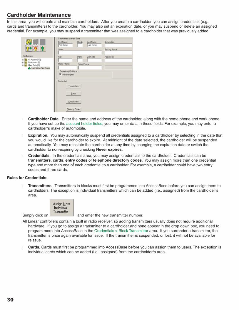
Cardholder Maintenance In this area, you will create and maintain cardholders. After you create a cardholder, you can assign credentials (e.g., cards and transmitters) to the cardholder. You may also set an expiration date, or you may suspend or delete an assigned credential. For example, you may suspend a transmitter that was assigned to a cardholder that was previously added.
Cardholder Data. Enter the name and address of the cardholder, along with the home phone and work phone. If you have set up the account holder fi elds, you may enter data in these fi elds. For example, you may enter a cardholder’s make of automobile.
Expiration. You may automatically suspend all credentials assigned to a cardholder by selecting in the date that you would like for the cardholder to expire. At midnight of the date selected, the cardholder will be suspended automatically. You may reinstate the cardholder at any time by changing the expiration date or switch the cardholder to non-expiring by checking Never expires.
Credentials. In the credentials area, you may assign credentials to the cardholder. Credentials can be transmitters, cards, entry codes or telephone directory codes. You may assign more than one credential type and more than one of each credential to a cardholder. For example, a cardholder could have two entry codes and three cards.
Rules for Credentials:
Transmitters. Transmitters in blocks must fi rst be programmed into AccessBase before you can assign them to cardholders. The exception is individual transmitters which can be added (i.e., assigned) from the cardholder’s area.
Simply click on and enter the new transmitter number.
All Linear controllers contain a built in radio receiver, so adding transmitters usually does not require additional hardware. If you go to assign a transmitter to a cardholder and none appear in the drop down box, you need to program more into AccessBase in the Credentials > Block Transmitter area. If you surrender a transmitter, the transmitter is once again available for issue. If the transmitter is suspended, or lost, it will not be available for reissue.
Cards. Cards must fi rst be programmed into AccessBase before you can assign them to users. The exception is individual cards which can be added (i.e., assigned) from the cardholder’s area.

31
Cardholder Maintenance (cont.)To Create a Card Number
Simply click on and enter the new card number.
Card readers and card reader interfaces are required for cards. If you go to assign a card to a cardholder and none appear in the drop down box, you need to program more into AccessBase in the Credentials > Cards area. If you surrender a card, the card is once again available for issue. If the card is suspended, or lost, it will not be available for reissue.
Entry Codes. You need Linear’s AM-KP entry keypads installed in order to utilize the entry codes capabilities of AccessBase. If you are installing Wiegand keypads by another manufacturer, you will enter the codes in via the card area. Consult with Linear Technical Services for application assistance when using keypads other than the AM-KP.
Directory Codes. In order to assign directory codes to cardholders, you must fi rst initialize the directory codes in the Telephone Directory area. By default, AccessBase will copy the fi rst name, last name and home phone number from the Cardholder Data fi elds and assign the next available directory code. You may change this information if needed.
To create a cardholder:
1. Click on the Create New Cardholder icon . The name of the cardholder set (e.g., “Staff”) will appear above the boxes where the name is entered.
2. Fill in the cardholder’s name, address etc. in the cardholder data fi elds. Assign Expiration date and fi ll in account holder fi elds if needed.
3. Assign credentials to the cardholder using the rules mentioned above.
4. Click APPLY.
Repeat steps 1 – 4 to create additional cardholders.
You may delete a cardholder by selecting the cardholder and clicking on .
You may manually suspend a cardholder by clicking on . Click again to reinstate.
Cardholder Icons:
Normal
Suspended
Expired

32
REPORTS Event Log Report The Event Log Report is a powerful tool that provides a history of the activities on the network.
To view the Event Log Report click on the AccessBase toolbar. Then select Event Log Report. Or simply press the F6 key.
Before you run an event log inquiry, it is recommended that you connect to the network and download the event log. Click on
and AccessBase will connect to each node in the network and download their events.
To get to the Event Log report area, go to VIEW > EVENT LOG REPORT, or press the F6 key.
You may run a full event log report by clicking on All Event Report. Access Base will display ALL of the events that have occurred in the network.
You may run a fi ltered event log by clicking on Generate Filtered Report. A fi ltered report can incorporate 5 different fi lters to customize your event log and to make it more manageable.
These are SUMMARY fi lters, meaning that AccessBase uses a summary of all fi lters that are selected.
For example, you could:
1. Select Access Granted from the Types tab.
2. Select door [A1A] Access_A from the Doors tab.
3. Click on Generate Filtered Report.
All access granted activity for this door will appear in the report. All other events will be fi ltered out and not displayed. Another example is to fi lter the event log to only show the activity of a certain door on certain days.
The fi lters that are available are the following:
Dates. You may specify only the dates that you want AccessBase to look at for creating the event log report.
Types. Types allow you to tell AccessBase which types of events you want in your event log report.
Doors. You can tell AccessBase to only pay attention to certain doors within your installation.
Cardholders. You can concentrate your efforts to only extract the events of certain cardholders.
Operators. Operators are events that are generated by the system or whoever is maintaining the system.

33
Event Log Report (cont.)
Click on to clear all fi lters. Often times, an effort to generate a fi ltered report that does not provide the desired results can be attributed to an errant fi lter being applied. Use the Uncheck All command to reset all fi lters.
In installations that have a large number of events captured in the event log, you may wish to Split Event Log. This makes the event log more manageable by only loading in the events that occurred since the last time the event log was split.
You may print out the event log if you have a printer that is recognized by Windows installed on the computer.
Transmitters Report The Transmitters Report shows you which transmitters are programmed into AccessBase and whom the transmitters are assigned to.
To view the Transmitters Report click on the AccessBase toolbar. Then select Various Reports.
Blocks. Select Blocks to see the different blocks of transmitters.
All. Select All to see who you have assigned transmitters to.
The following column headings will be displayed when a report of transmitter blocks is selected:
These columns can be sorted by clicking on any of the column headings. This sort feature applies to all report types listed below (e.g., Cards, Cardholders, Entry Codes, etc.)
You may print out the transmitter report if you have a printer that is recognized by Windows installed on the computer.
Cards Report The Cards Report shows you which cards are programmed into AccessBase and whom the cards are assigned to.
To view the Cards Report click on the AccessBase toolbar. Then select Various Reports.
Blocks. Select Blocks to see the different blocks of cards
All. Select All to see who you have assigned cards to.
You may print out the card report if you have a printer that is recognized by Windows installed on the computer.
Cardholders Report The Cardholders Report shows you which cardholders are in the system, along with their pertinent data.
To view the Cardholders Report click on the AccessBase toolbar. Then select Various Reports.
Cardholders. This will show you the status of the cardholders, their address, phone numbers and account holder data (if any). Click on Include Credentials to see all of this information PLUS which credentials are assigned to the cardholder.
You may print out the cardholder report if you have a printer that is recognized by Windows installed on the computer.

34
Entry Codes Report The Entry Codes Report shows which entry codes are in the system and whom the entry codes are assigned to.
To view the Entry Codes Report click on the AccessBase toolbar. Then select Various Reports.
You may print out the entry code report if you have a printer that is recognized by Windows installed on the computer.
Directory Codes Report The Directory Codes Report shows which directory codes are in the system. For each directory code, you will see the name that appears on the telephone entry, the telephone number that the telephone entry will dial and whether or not the directory code has extended talk time enabled.
To view the Directory Codes Report click on the AccessBase toolbar. Then select Various Reports.
You may print out the directory code report if you have a printer that is recognized by Windows installed on the computer.
System Report The System Report is a troubleshooting tool that displays exhaustive information about how the system is programmed. It also displays the memory status of all of the controllers in the installation.
To view the System Report click on the AccessBase toolbar. Then select Various Reports.
You may be asked to run this report if the system is not functioning as you would expect.
You may print out the system report if you have a printer that is recognized by Windows installed on the computer.

35
Printing Reports There are two types of reports that can be printed from AccessBase.
Event Log Report
• Press the <F6> key to navigate to the Event Log Report screen.
• Click the All Event Report button to display the Event Log.
• Click the Print button. This will bring up the Microsoft Windows Print dialog which allows you the option of customizing your printout. For example, you may fi nd that landscape orientation provides a better printout that portrait orientation.
Various Reports
• Select Various Reports from the toolbar • Click the appropriate button to display any credential type shown on the screen. You can also display detailed
information about your installation by selecting System Report.
• The column widths on the screen can be adjusted to achieve better alignment for your printouts. This may require several attempts before you fi nd column widths that give you the desired results. These column settings are saved in the registry when you close AccessBase. Therefore you should only have to set them one time.
• Click the Print button which will bring up the same Windows Print Dialog as when you print Event Logs.
➤ NOTE: The default font for printing is Courier New. This font has proven to be the font of choice for those using inkjet printers such as the HP DeskJet series. However some LaserJet printers exhibit better printouts of AccessBase reports with the font Times New Roman.
You can change the font in AccessBase from the Printer tab. To display the Printer tab select SETUP > ACCESSBASE. When you click the Printer tab you can then select a font as shown below.
36
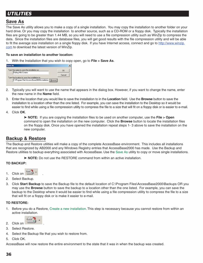
UTILITIES Save As The Save As utility allows you to make a copy of a single installation. You may copy the installation to another folder on your hard drive. Or you may copy the installation to another source, such as a CD-ROM or a fl oppy disk. Typically the installation fi les are going to be greater than 1.44 MB, so you will need to use a fi le compression utility such as WinZip to compress the data. Since the installation fi les are database fi les, you will get good results with the fi le compression utility and will be able to fi t the average size installation on a single fl oppy disk. If you have Internet access, connect and go to http://www.winzip.com to download the latest version of WinZip.
To save an installation to another location:
1. With the Installation that you wish to copy open, go to File > Save As .
2. Typically you will want to use the name that appears in the dialog box. However, if you want to change the name, enter
the new name in the Name fi eld.
3. Enter the location that you would like to save the installation to in the Location fi eld. Use the Browse button to save the installation to a location other than the one listed. For example, you can save the installation to the Desktop so it would be easier to fi nd while using a fi le compression utility to compress the fi le to a size that will fi t on a fl oppy disk or is easier to e-mail.
4. Click OK.
➤ NOTE: If you are copying the installation fi les to be used on another computer, use the File > Open command to open the installation on the new computer. Click the Browse button to locate the installation fi les on the fl oppy disk. Once you have opened the installation repeat steps 1- 3 above to save the installation on the new computer.
Backup & Restore The Backup and Restore utilities will make a copy of the complete AccessBase environment. This includes all installations that are recognized by AB2000 and any Windows Registry entries that AccessBase2000 has made. Use the Backup and Restore utilities to backup everything associated with AccessBase. Use the Save As utility to copy or move single installations.
➤ NOTE: Do not use the RESTORE command from within an active installation.
TO BACKUP:
1. Click on .2. Select Backup.
3. Click Start Backup to save the Backup fi le to the default location of C:\Program Files\AccessBase2000\Backups OR you may use the Browse button to save the backup to a location other than the one listed. For example, you can save the backup to the Desktop where it would be easier to fi nd while using a fi le compression utility to compress the fi le to a size that will fi t on a fl oppy disk or is make it easier to e-mail.
TO RESTORE :
1. Before you do a Restore, Create a new installation. This step is necessary because you cannot restore from within an active installation.
2. Click on .3. Select Restore.
4. Select the Backup fi le that you wish to restore from.
5. Click OK.
AccessBase will now restore the entire environment to the state that it was in when the backup was created.

37
Set Date & Time The Date & Time utility will set the date and time of the network to match that of the computer. Before using this command, make sure that the date and time on your computer is correct.
To set the date and time for the network:
1. Connect to the network.
2. Click on .The date and time stamp applied to the event log and real time events monitoring will be correct.
Download All Memory The Download All Memory is a trouble shooting tool that will allow you to connect to and diagnose individual nodes of networks. This tool can also be used by a computer other than the one that is maintaining the system. Once downloaded, a program called AccessView will come up and allow you to view the various settings. You will not be able to view the actual cardholder names since the names are not stored on the node. The actual names are stored in the actual computer that is maintaining the system. The user of the computer that is maintaining the system can run a report from the Cardholder Reports area that will give you an index number that corresponds to the index that appears in AccessView.
To Download All Memory:
1. Make sure there are no commands in the queue, then Connect to the network.
2. Click on the node and go to Setup > Download All Memory.
3. You will see AccessBase download the contents of the controller’s fl ash memory. This process can take anywhere from 3 to 10 minutes.
4. Once the download is complete, AccessView will open up and you will be able to view the information from the node.
AccessView allows you to VIEW the information from the node. Any changes MUST be performed from the computer that is currently maintaining the installation.
➤ NOTE: When using this tool from a computer other than the one that is maintaining the system, do
not click on . This will reprogram the network with the information from your computer. This will overwrite the current information at the network. The system will no longer function as desired. If this occurs, you will have to connect to the network with the computer that normally maintains the
installation and press the to reprogram the installation with the correct information.

38
Auto-Update & Auto-Backup When you add AccessBase to your Windows Task Scheduler you can perform the following tasks automatically depending on which switch you choose. (See below for switch options \A and \B.) If AccessBase is already running when the Task Scheduler attempts to run a second instance, the fi rst instance will be closed.
Auto-Update (switch \A)
• Program the network (i.e., add to the network queue) if the Program Network button was highlighted when AccessBase was last closed.
• Connect to the network and send all commands in the queue.
• Download the event log for all networks.
Auto-Backup (switch \B)
Backup your installations in the same way as clicking on when you are running AccessBase 2000.
Task Scheduler
AccessBase can be added to the Task Scheduler from the Control Panel.
1. Go to the Start > Settings > Control Panel and select Scheduled Tasks > Add Scheduled Task.
2. In the Scheduled Task Wizard select Linear AccessBase2000, then click Next. Alternatively, you can use the Browse button to select AB200.EXE. If you use the Browse button, see the note below.
3. Select the button named Daily, then click Next.
4. In the Time and Day dialog you can use the defaults by clicking Next.
5. If you are prompted for a password and you do not have a password you need to go to the User Accounts applet in the Control Panel and create a password. Otherwise you cannot run AccessBase from the Task Scheduler.
6. After entering your password click Next.
7. Now click Finish.
The command line switches \A and \B can be added using the following steps:
1. Go to Start > Programs > Accessories > System Tools > Scheduled Tasks. (You can make this a desktop icon by right-clicking and sending the shortcut to the desktop.)
2. After you open Scheduled Tasks, right-click on the AccessBase task in the Scheduled Tasks window that is displayed and select Properties.
3. In the ‘Run’ window type \A, then click OK. This will cause AccessBase to auto-update the last installation you used.

39
Auto-Update & Auto-Backup (cont.)Auto-Update - Last Opened Installation
Auto-Update: This argument is used to run the selected action on the last opened installation automatically. Notice that the Task Scheduler Wizard creates the path in DOS 8.3 format.
Example: C:\PROGRA~1\ACCESS~2\AB2000.exe \A
Auto-Update - Minimized: This argument is used to run the selected action on the last opened installation automatically and minimized.
Example: C:\PROGRA~1\ACCESS~2\AB2000.exe \AM
Auto-Update - Specifi c Installation
Auto-Update: This will run the selected action on a specifi c installation automatically. Note: You cannot auto-update a specifi c installation with AB.EXE minimized.
Example: C:\PROGRA~1\ACCESS~2\AB2000.exe “Acme Manufacturing(DEMO)\Acme Manufacturing(DEMO).abi”
Auto-Backup
Auto-Backup: This will run the selected action automatically.
Example: C:\PROGRA~1\ACCESS~2\AB2000.exe \B
Auto-Backup - Minimized: This will run the selected action automatically and minimized.
Example: C:\PROGRA~1\ACCESS~1.52\AB2000.exe \BM
Note: If you use the Browse button to select AB2000.EXE, then the Scheduled Task Wizard will enclose the path and fi lename in double-quotes. For example,
“C:\Program Files\AccessBase2000\AB2000.exe”
Therefore, the command line arguments must be placed outside the double quotes in the ‘Run’ window. For example,
“C:\Program Files\AccessBase2000\AB2000.exe” \A
or
“C:\Program Files\AccessBase 2000\AB2000.exe” “Acme Manufacturing(DEMO)\Acme Manufacturing(DEMO).abi”
Task Scheduler Log
AccessBase 2000 will record the Auto-Update & Auto-Backup activities in a log fi le named Task Scheduler Log. It is located within the root folder of AccessBase. The default location is C:\Program Files\AccessBase2000. In addition, a shortcut to the Task Scheduler is created and placed in the Start Menu. Clicking on this shortcut will open up Windows Notepad where the contents of Task Scheduler Log can be viewed.

40
Administrators and Operators Administrators have unlimited access to all features of AccessBase.
Operators have restricted access to AccessBase. These restrictions are defi ned by an Administrator in Setup > AccessBase > Operators.
Network Network refers to the system that AccessBase 2000 will be programming. A network can consist of one to eight controllers (nodes) connected together either directly via RS-485 or dial-up via modem.
Direct Connect Use the A2C/DB-9 cable if your COM port is a 9-pin and an A2C/DB-25 if your COM port is a 25-pin style. Most computers sold today come with at least one 9-pin connector and it is usually assigned to COM1 or COM 2.
Dial Up Since AccessBase 2000 uses the same modem that other programs on your computer uses, if you can connect to the Internet chances are your modem will work fi ne with AccessBase 2000.
Modem In order to eliminate possible compatibility issues, Linear strongly recommends that you use a LinModem at the controller.
Nodes Nodes refer to the individual controllers found within the network.
Program Network Overview
Anytime you see the Program Network enabled, there is data to be sent to the network. In addition, an icon will be placed in your system tray to serve as a visual reminder. This will remain even if AccessBase is minimized. You must be on line with the network in order to program the network
MGT Wireless supervised gate edge transmitter. An edge sensor, such as a tape switch or a safety edge is connected to the MGT. When the edge sensor strikes another object, the MGT sends a signal to the controller. The controller supervises the MGT for battery, status and tamper. Any of these events will cause the MGT report the trouble condition to the controller.
Door Ajar Time The amount of time that the door can remain open before a relay set for alarm is activated.
Extended Talk Time When enabled, the cardholder / directory code will be allowed double the amount of standard talk time.

41
INDEX
AAccessBase 2000 Setup 3
Account Holder Fields 6Advanced 6Database Optimization & Event Log 5Defi ne Operators 3Dialing 4Opening AccessBase 2000 3
Administrators and Operators 40
BBackup 36Button Schedule 22
CCardholders 29
Cardholder Maintenance 30Cardholder Sets 29
Cardholders Report 33Cards Report 33Clear the queue 7Connect to the Network 10Create A New Installation 8Credentials 25
Cards 26Directory Codes 28Entry Codes 27Transmitters 25
DDatabase Optimization & Split Event Log 5Defi ne Operators 3Dialing 4Dial Up 40Directory Begins At 23Directory Codes 28Directory Codes Report 34Directory Code Length 23Direct Connect 40Door Ajar Time 40Door Schedules 21Download All Memory 37
EEntry Codes 27Entry Codes Report 34Event Log Report 32Extended Talk Time 40
FFacility Codes 22Features in AccessBase 2
GGetting Started 8
Communications Setup 9Connect to the Network 10Create A New Installation 8Opening Existing Installation 8
Global 19Button Schedule 22Door Schedules 21Facility Codes 22Telephone Directory 23Time & Calendar 24Time Zones 20Validation Groups 19
IInstall Nodes 11Introduction to AccessBase 2
MMGT 40Modem 15, 40
NNetwork 40Nodes 40Node General 18Node Setup 11
Install Nodes 11Modem 15Node Confi guration 12Node General 18Obstacle Transmitters 18Passwords 15Relays 13Remote Device 16
OObstacle Transmitters 18Opening AccessBase 3Open Existing Installation 8Operators 3Overview of AccessBase 2000 2
PPasswords 15PBX Digital Dialing 23Postal Key Door 23Printing Reports 35Program Network Overview 40
RRelays 13Remote Device 16Reports 32
Cardholders Report 33Cards Report 33Directory Codes Report 34Entry Codes Report 34Event Log Report 32Printing Reports 35System Report 34Transmitters Report 33
Restore 36
SSave As 36Set Date & Time 37Systems Report 34System Requirements 2
TTalk Time 23Telephone Directory 23Time & Calendar 24Time Zones 20Transmitters 25Transmitters Report 33
UUtilities 36
Auto-Update & Auto-Backup 38Backup & Restore 36Download All Memory 37Save As 36Set Date & Time 37
VValidation Groups 19

Copyright © 2005 Linear LLC 224134 X2