accelerated concept to product (acp) process highly .../media/files/autosteel/great designs in...
TRANSCRIPT
Innovative CAE Solutions
Accelerated Concept to Product (ACP) Process
Highly Optimized Longitudinal Rail
Achieving 45% Mass Reduction
w w w . a u t o s t e e l . o r g
FutureSteelVehicle (FSV) Design Methodology
Akbar Farahani, PhD.ETA Inc.

Innovative CAE Solutions
AGENDA
• Introduction
• Background
• Objective
• FSV Methodology (ACP Process)
• FSV Pilot Rail Project
w w w . a u t o s t e e l . o r g
• FSV Pilot Rail Project
• FSV Pilot Project Process, Results and outcome
• Conclusion
• Q/A
Innovative CAE Solutions
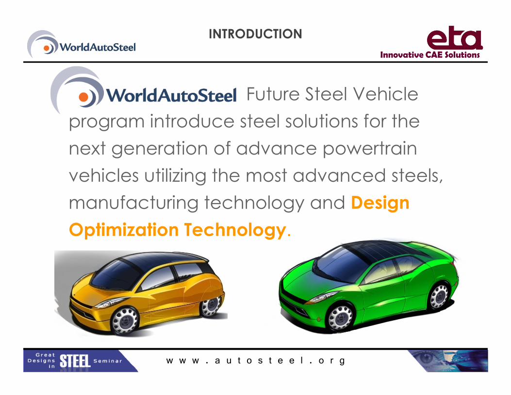
INTRODUCTION
Future Steel Vehicle
program introduce steel solutions for the
next generation of advance powertrain
vehicles utilizing the most advanced steels,
manufacturing technology and Design
w w w . a u t o s t e e l . o r g
manufacturing technology and Design
Optimization Technology.

Innovative CAE Solutions
BACKGROUND
• FGPC (Future Generation Passenger Compartment)
Phase 1 & 2 projects supported by A/SP have
previously validated the major portions of this design
and development process if starting point is an existing
structure (Current Production or Benchmarking
vehicle)
– Phase 1- Used ULSAB-AVC (Donor) with 30% potential mass
w w w . a u t o s t e e l . o r g
– Phase 1- Used ULSAB-AVC (Donor) with 30% potential mass
reduction
– Phase 2- Used GM (Donor ) vehicle with 15% to 20% potential mass reduction

Innovative CAE Solutions
BACKGROUND
• The Accelerated Concept to Product (ACP) Process
looks into a fresh new product with no information
from the producer.
– The method first defines the optimum loadpath of a clean
sheet design by blocking out the initial structure.
– It continues with the previous proven methods developed by
FGPC Phase 1 & 2.
w w w . a u t o s t e e l . o r g
FGPC Phase 1 & 2.
– New tasks have been added to the ACP Process since the
completion of this project.
Innovative CAE Solutions
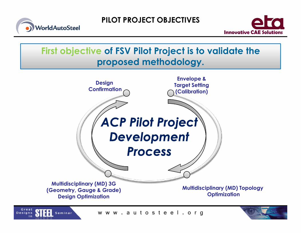
PILOT PROJECT OBJECTIVES
Envelope & Target Setting(Calibration)
Design Confirmation
ACP Pilot ProjectACP Pilot Project
First objective of FSV Pilot Project is to validate the
proposed methodology.
w w w . a u t o s t e e l . o r g
Multidisciplinary (MD) 3G(Geometry, Gauge & Grade)
Design Optimization
Multidisciplinary (MD) Topology Optimization
ACP Pilot Project
Development
Process
ACP Pilot Project
Development
Process

Innovative CAE Solutions
PILOT PROJECT OBJECTIVES
Donor Vehicle
Pilot Project Baseline
Second objective is apply methodology to A/SP LWFE
Front Rail & establish additional mass savings
w w w . a u t o s t e e l . o r g
Rail: 16.34kg
System
mass reduction: -22.4%
Rail: 12.25kg
Pilot Project Baseline
System
mass reductions:
TWT No. 2: -26.5%
TWT No. 3: -31.8%
A/SP LWB
Concept

Innovative CAE Solutions
Styling Packaging Parameters Predecessor New Design
CAD/FEAPart Models
Courtesy of SFE Concept
ACP PROCESS ADVANTAGES
Fresh Product and New ArchitectureStyling/Packaging/Topology/Geometry/Grade/Gage
w w w . a u t o s t e e l . o r g
Styling/Packaging/Topology/Geometry/Grade/GageAdvantages/Returns� Comprehensive Goals Achievable.
� Synchronized Engineering Design, CAE and CAD.
� Greatest Possible Mass Reduction.
� Robust Design & overall efficiency improvements.
� Reduce # of Parts, Efficient Manufacturing (reduce cost of Labor,
Material and Tooling).
InvestmentNew Process, tooling/manufacturing process/prototyping and Testing

Innovative CAE Solutions
PROJECT OVERVIEW
Approx definition of Design Space
MD Topology
Optimization
PrimaryDesign Envelope
w w w . a u t o s t e e l . o r g
Concept Design
MD 3G DesignOptimization
Parameterized Design Envelope

Innovative CAE Solutions
• Front Rail Pilot Project to validate methodology1. Block out Design Envelope
2. Topology Optimization
3. Parameterize Geometry
4. Design Optimization constraints
5. Detailed Geometry (Shape), Gauge (thickness) & Grades (material)
MD 3G Optimization
FRONT RAIL SETUP
w w w . a u t o s t e e l . o r g
• Optimization MD Load Cases– NCAP Front Impact
– IIHS Front Impact 40% ODB
– Static Stiffness
• Torsional
• Bending

Innovative CAE Solutions
TOPOLOGY OPTIMIZATION
DESIGN SPACE
Existing Front Rail Geometry (shown only for reference)
Design Space, the extreme packaging volume available to the
optimization. New Front Longitudinal Rail must fit within this space
Top View
w w w . a u t o s t e e l . o r g
Bottom View
Innovative CAE Solutions
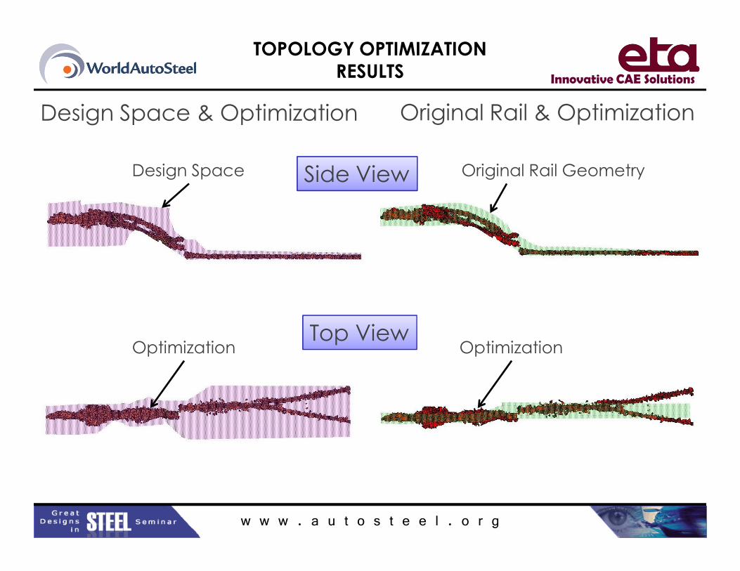
TOPOLOGY OPTIMIZATION
RESULTS
Side View
Design Space & Optimization Original Rail & Optimization
Design Space Original Rail Geometry
w w w . a u t o s t e e l . o r g
Top ViewOptimization Optimization
Innovative CAE Solutions
• 1st Topology Optimization provides:
– An initial load path, the base for Optimum Dynamic
Load path and MD 3G optimization
– Insight into how the structure should be designed
(free from traditional design thought process)
TOPOLOGY OPRIMIZATION
RESULTS
w w w . a u t o s t e e l . o r g
(free from traditional design thought process)
• Topology optimization is an iterative process

Innovative CAE Solutions
MD 3G
MD OPTIMIZATION
MD 3G DESIGN OPTIMIZATION
PROCESS
w w w . a u t o s t e e l . o r g
MD 3G
Design
Optimization(Geometry, Gauge & Grade)
DESIGN SIMULATIONAnalysis Tools (Static, Dynamic)

Innovative CAE Solutions
GEOMETRY
PARAMETERIZATION
• Longitudinal Rail must fit within Design Space
Planes cut through mesh
Equivalent planes cut through Design Space
• 15 cross-sectional stations along length of B-Spline
w w w . a u t o s t e e l . o r g
• Baseline longitudinal Rail within design space
Innovative CAE Solutions
CROSS-SECTIONAL
DESCRIPTIONS
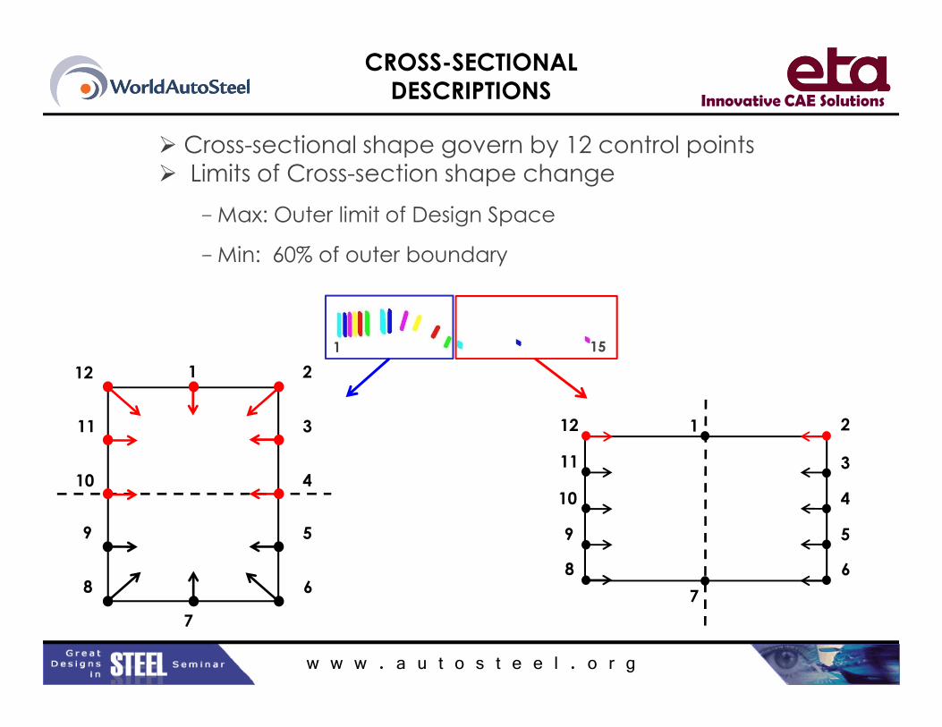
� Cross-sectional shape govern by 12 control points
� Limits of Cross-section shape change
– Max: Outer limit of Design Space
– Min: 60% of outer boundary
1 212
1 15
w w w . a u t o s t e e l . o r g
1 2
3
4
5
6
9
8
7
10
11
12
1 2
3
4
5
6
9
8
7
10
11
12
Innovative CAE Solutions
MD 3G DESIGN OPTIMIZATION
PROBLEM STATEMENT
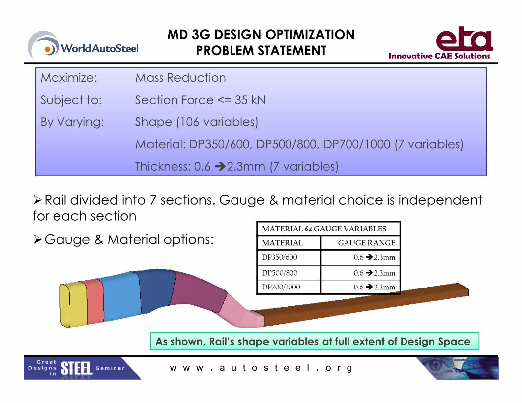
Maximize: Mass Reduction
Subject to: Section Force <= 35 kN
By Varying: Shape (106 variables)
Material: DP350/600, DP500/800, DP700/1000 (7 variables)
Thickness: 0.6 �2.3mm (7 variables)
�Rail divided into 7 sections. Gauge & material choice is independent
w w w . a u t o s t e e l . o r g
�Rail divided into 7 sections. Gauge & material choice is independent
for each section
�Gauge & Material options:MATERIAL & GAUGE VARIABLES
MATERIAL GAUGE RANGE
DP350/600 0.6 �2.3mm
DP500/800 0.6 �2.3mm
DP700/1000 0.6 �2.3mm
As shown, Rail’s shape variables at full extent of Design Space

Innovative CAE Solutions
FINAL DESIGN
SECTION MATERIAL GAUGE
(mm)
MASS
(kg)
1 DP350/600 1.0 0.48
2 DP500/800 1.0 0.46
3 DP700/1000 0.7 0.64
4 DP500/800 1.5 0.99
Side Top
123
4
5
ISO
w w w . a u t o s t e e l . o r g
4 DP500/800 1.5 0.99
5 DP700/1000 2.0 1.58
6 DP700/1000 2.3 3.53
7 DP700/1000 1.5 0.69
8 DP700/1000 0.8 0.37
9 DP700/1000 0.6 0.26
TOTAL 8.98MASS:
Baseline A/SP LWFE-LWB (: 12.25kg)
Final Design: 8.98kg (-27%baseline)
6
7
89
Manufacturing
constraints were not applied

Innovative CAE Solutions
MD 3G OPTIMIZED
and BASELINE DESIGN
TopISO
w w w . a u t o s t e e l . o r g
Side

Innovative CAE Solutions
FINAL DESIGN:
NCAP PERFORMANCE
Baseline
Final Design
w w w . a u t o s t e e l . o r g

Innovative CAE Solutions
FINAL DESIGN:
NCAP PERFORMANCE
Baseline Final Design
w w w . a u t o s t e e l . o r g

Innovative CAE Solutions
FINAL DESIGN:
40% ODB PERFORMANCE
Good
Accepta
ble
Marginal
Poor
w w w . a u t o s t e e l . o r g

Innovative CAE Solutions
FINAL DESIGN:
STATIC STIFFNESS
Torsional Stiffness
Final Design: 17,094 Nm/deg
Baseline: 17,788 Nm.deg
Bending Stiffness
Final Design: 11,870 N/mm
Baseline: 12,122 N/mm
w w w . a u t o s t e e l . o r g

Innovative CAE Solutions
SUMMURY of RESULTS
8
10
12
14
16
18
MA
SS
(k
g)
Front Rail: Donor Vehicle, LWFE & FSV Pilot Project Comparison
Donor Vehicle
LWFE: LWB
FSV: Final Design
-25% -45%
-27%
% DONOR VEHICLE
% LWFE-LWB
w w w . a u t o s t e e l . o r g
New Design Optimization Method (Topology & 3G) proven effective
Mass reduction: 27% over LWFE-LWB (A/SP optimized design)
45% over Donor Vehicle
DONOR VEHICLE LWFE-LWB FSV FINAL DESIGN
16.34kg 12.25kg 8.98kg
0
2
4
6
1
MA
SS
(k
g)
FSV: Final Design

Innovative CAE Solutions
MD 3G OPTIMIZATION
MASS RESPONSE
8
10
12
14
16
Ma
ss
(k
g)
Mass Variation During Optimization Individual Evaluation
Baseline Design
CBD (Current Best Design)
CBD Trendline
w w w . a u t o s t e e l . o r g
0
2
4
6
8
0 200 400 600 800 1000 1200
Ma
ss
(k
g)
Evaluation Number

Innovative CAE Solutions
CONCLUSION
ACP Design Process
• Provides guidance for optimum load path
unconstrained by historical engineering judgment.
• Develops non-intuitive solutions for structural
performance.
w w w . a u t o s t e e l . o r g
• Develops non-intuitive optimized shapes and
component configuration.
• ACP Design Process applied to Future Steel Vehicle
program will be applied to the full structure and
address manufacturing constraints.