abstract recent advances in mechanics...
TRANSCRIPT

Abstract
Recent Advances in Mechanics Engineering
By
Shishir Kr. Sahu, NIT Rourkela, India
The world community is experiencing plenty of construction activities for
infrastructure including High rise buildings, airports, stadiums, rails, bridges, low
cost housing for the poor and so on. Besides this, the engineers are working on
interdisplinary areas of automotive, naval and especially aerospace engineering.
The global research community is working towards new materials including smart
and nanocomposites, its characterization and utilization of new materials and
product development for specific applications. The advances in digital computers
with their enormous computing speed, core memory capacity has changed the
outlook of the structural analysis. This also caused the evolution and advancement
of various numerical methods such as Finite element method (FEM), meshless
methods for solution of static, dynamic and stability analysis of one dimensional
beams and frames to multi-dimensional plates and shells. The advances in
experimental mechanics give an insight to the actual behavior of structure. The
various advances in mechanics engineering are discussed in this study.

Recent Advances in Mechanics
Engineering
Presented By
Dr. Shishir Kumar Sahu
Professor, Department of Civil Engineering
National Institute of Technology,
Rourkela, India
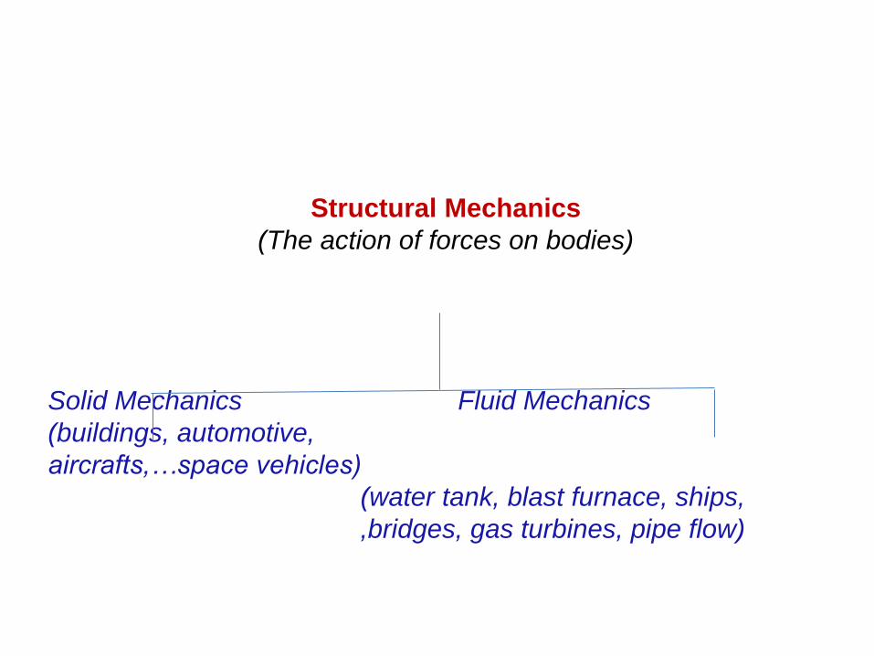
Structural Mechanics
(The action of forces on bodies)
Solid Mechanics Fluid Mechanics
(buildings, automotive,
aircrafts,…space vehicles)
(water tank, blast furnace, ships,
,bridges, gas turbines, pipe flow)
Solid Mechanics
• This is the field of science deals with mechanics of solid structures including machines, buildings, bridges, automobiles, aerospace and naval structures.
• High speed digital computers changed the direction of solid mechanics.
• Mainly due to high performance computing involved in the modelling of systems with numerical techniques for static, dynamic and stability problems.
• Complicated geometry, boundary conditions and non-uniform loadings, dynamics, nonlinearity can be handled easily.
• Complicated Industrial problems solved by software packages like ANSYS, ABACUS, ALGOR, NASTRAN, PLAXYS, SAP, STAAD Pro etc….
• Various methods include analytical, numerical like Ritz, finite difference, method of multiple scales and Finite Element methods and experimental techniques.
• The current trends of development: emphasis on dynamics, analyzing and experimenting the failure and damage of structures including inverse problems of damage detection through soft computing techniques to preserve structural integrity.
Some Recent Developments
• FRP Composites
• Metal fiber laminates
• Functional graded materials
• Nanotechnology
• Smart Structures
• Structural health monitoring
• Mesh free finite element
• Multi-scale modeling
• Earthquake resistant design
• Spectral finite element
• Modal testing

FRP Composites
Definition
Composite materials are made by mixing two or
more distinct materials, having a macroscopically
recognizable interface
Fibre Reinforced Polymer (FRPs) are a class of
Composite materials, which are composed of
fibres embedded in an adhesive Polymer/matrix
environment.
Types of Composite Materials
Fiber and Matrix
Fiber: Glass, Carbon, Aramid, Hybrid
Type of material based on Matrix
- Polymer Matrix Composites (PMC)
- Ceramic Matrix Composites (CMC)
- Metal Matrix Composites (MMC)
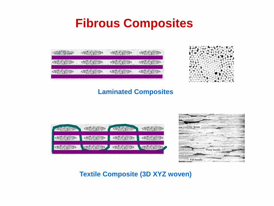
Laminated Composites
Textile Composite (3D XYZ woven)
Fibrous Composites
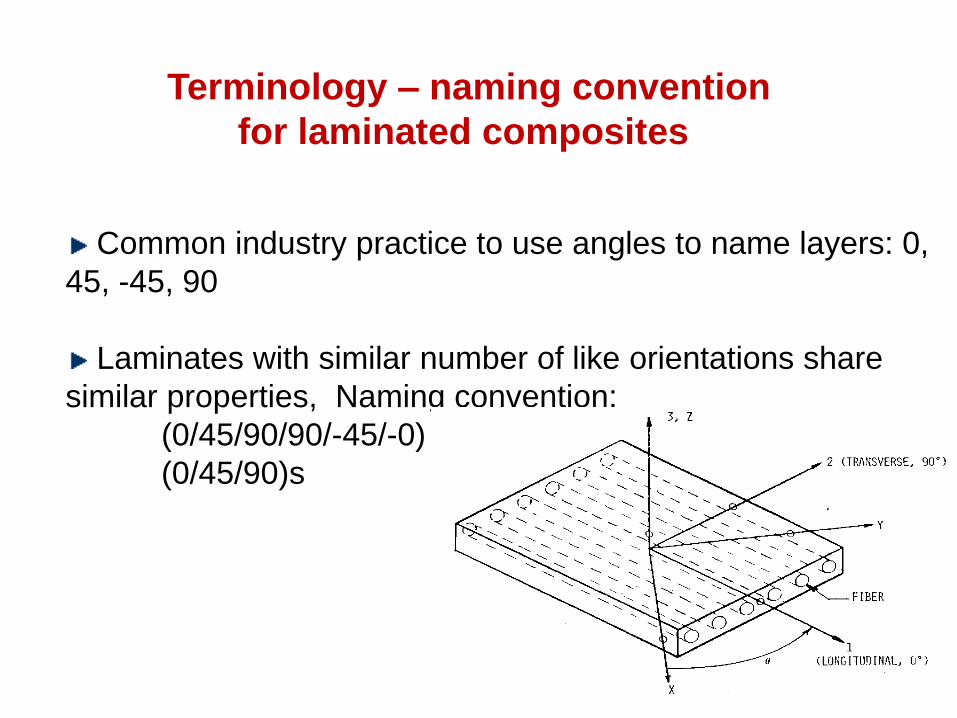
Common industry practice to use angles to name layers: 0,
45, -45, 90
Laminates with similar number of like orientations share
similar properties, Naming convention:
(0/45/90/90/-45/-0)
(0/45/90)s
Terminology – naming convention
for laminated composites
FRP Composites:
greatest invention of twentieth century.
Applications:
Aerospace Structures
Automobile Engineering
Nuclear Sector
Marine Engineering
Civil Engineering
Sports goods and many
Other Industrial Fields….
PROPERTIES OF COMPOSITES
. Light Weight
. High Specific Strength And Stiffness
. Low Density
. High Corrosion Resistance
. Longer Durability
. High Internal Damping
. Low Maintenance Cost

• The tensile strength of composites is four to six times greater than that of steel or aluminum.
• The strength to weight ratio of FRP is 18 times that of steel and 50 times that of concrete.
• FRP materials are 30-40% lighter than aluminum structure.
• Besides military aircrafts like F-35, even the recent Boeing-787, Airbus-350 passenger plane uses more than 50% of composites in wings, fuselage and other components in comparison to Boeing-777 models.
• The composite bridge in Oxford, the Avantime passenger car, Kenwood truck, the award winning Oracle sail boat are some applications of FRP composites.
• The F-35 lightening II will be the first mass-produced aircraft to integrate structural nanocomposites in non-load bearing airframe components.
• Meanwhile, the same carbon nanotube reinforced polymer (CNRP) material is being considered to replace about 100 components made with other composites or metals throughout the F-35's airframe.
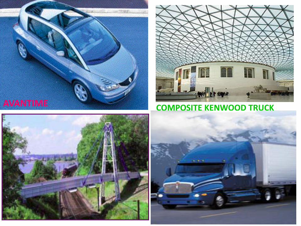
AVANTIME COMPOSITE KENWOOD TRUCK
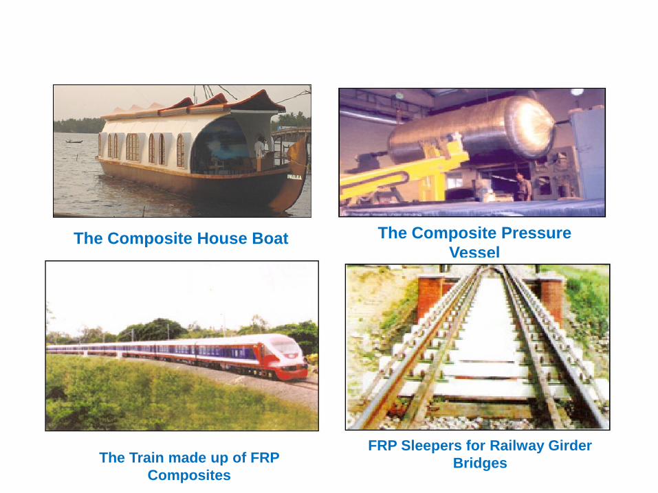
The Composite House Boat The Composite Pressure
Vessel
The Train made up of FRP
Composites
FRP Sleepers for Railway Girder
Bridges

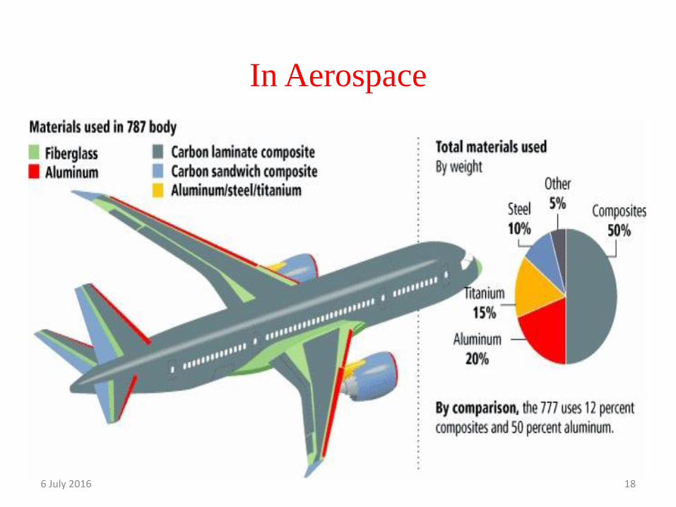
In Aerospace
6 July 2016 18

Airbus 350/Airbus 380
Full Composite wing and Fuselage panels made from CFRP

F35 Lightening II
First mass produced aircraft with Carbon Nano Composite

BMW Oracle sailboat, winner of the 33rd America’s Cup
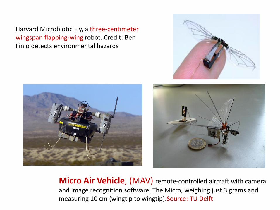
Harvard Microbiotic Fly, a three-centimeter wingspan flapping-wing robot. Credit: Ben Finio detects environmental hazards
Micro Air Vehicle, (MAV) remote-controlled aircraft with camera
and image recognition software. The Micro, weighing just 3 grams and measuring 10 cm (wingtip to wingtip).Source: TU Delft

METAL FIBER LAMINATE
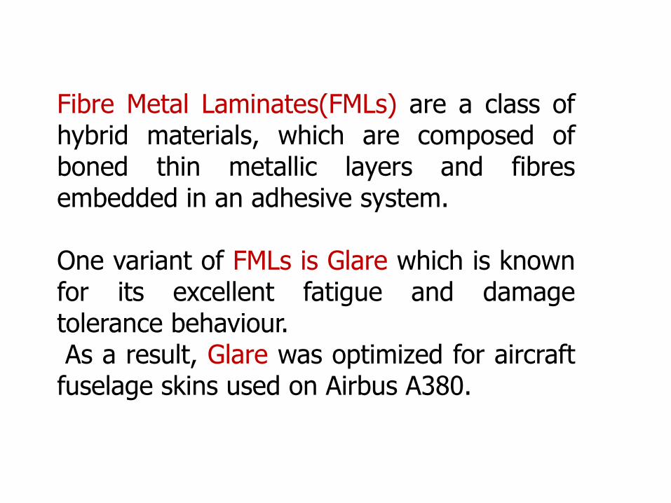
Fibre Metal Laminates(FMLs) are a class of hybrid materials, which are composed of boned thin metallic layers and fibres embedded in an adhesive system. One variant of FMLs is Glare which is known for its excellent fatigue and damage tolerance behaviour. As a result, Glare was optimized for aircraft fuselage skins used on Airbus A380.
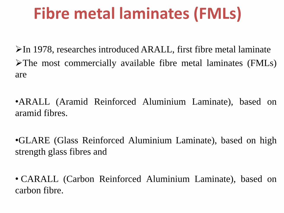
Fibre metal laminates (FMLs)
In 1978, researches introduced ARALL, first fibre metal laminate
The most commercially available fibre metal laminates (FMLs)
are
•ARALL (Aramid Reinforced Aluminium Laminate), based on
aramid fibres.
•GLARE (Glass Reinforced Aluminium Laminate), based on high
strength glass fibres and
• CARALL (Carbon Reinforced Aluminium Laminate), based on
carbon fibre.
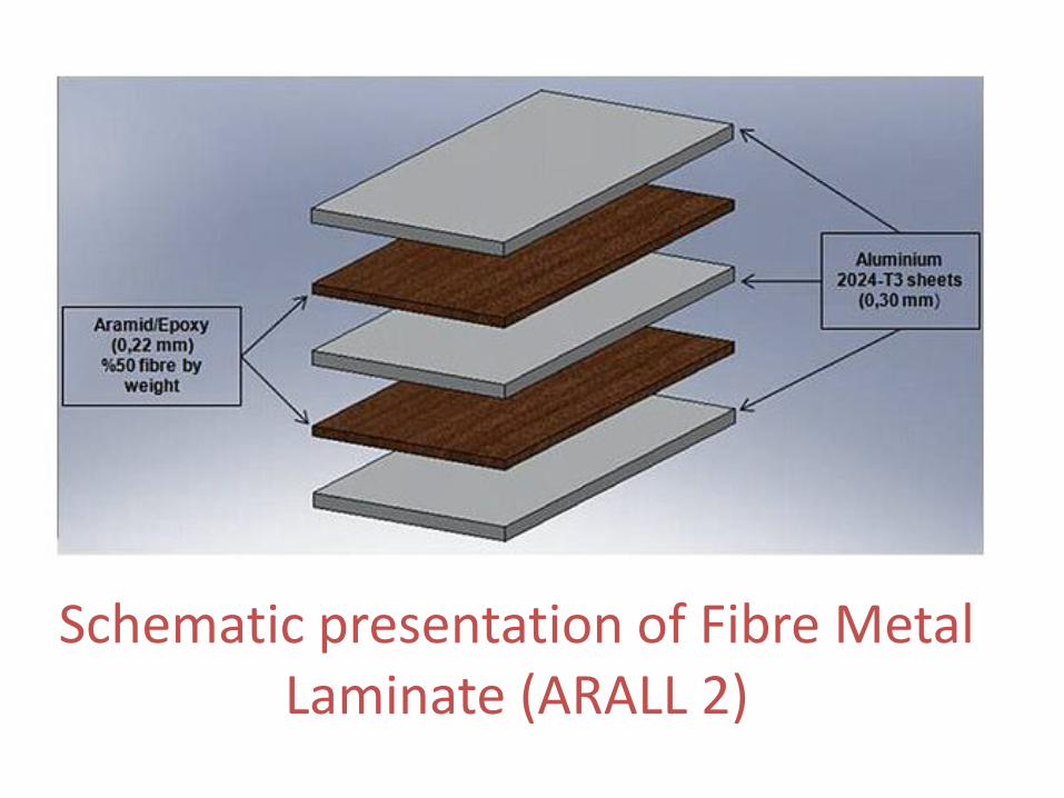
Schematic presentation of Fibre Metal Laminate (ARALL 2)

Schematic illustration of a cross-ply GLARE laminates
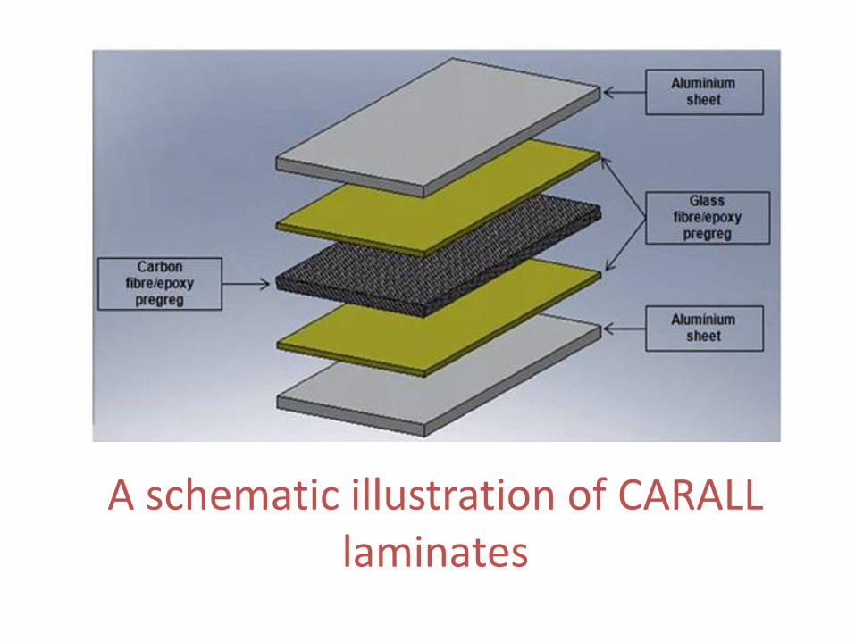
A schematic illustration of CARALL laminates
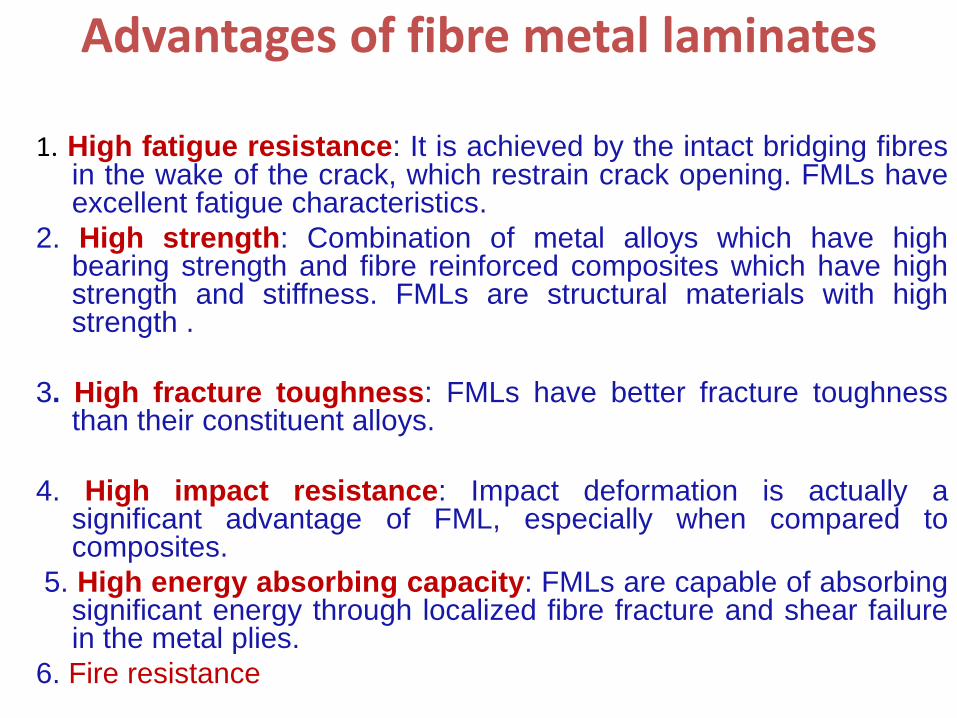
Advantages of fibre metal laminates
1. High fatigue resistance: It is achieved by the intact bridging fibres
in the wake of the crack, which restrain crack opening. FMLs have excellent fatigue characteristics.
2. High strength: Combination of metal alloys which have high bearing strength and fibre reinforced composites which have high strength and stiffness. FMLs are structural materials with high strength .
3. High fracture toughness: FMLs have better fracture toughness than their constituent alloys.
4. High impact resistance: Impact deformation is actually a significant advantage of FML, especially when compared to composites.
5. High energy absorbing capacity: FMLs are capable of absorbing significant energy through localized fibre fracture and shear failure in the metal plies.
6. Fire resistance
• FMLs are attractive to various industrial applications (military, automotive and aircraft).
• FMLs are finding great use in most commonly in aerospace applications.
• Both ARALL and GLARE laminates are now being used as structural materials in aircrafts. Fibre Metal Laminates have been successfully introduced into the Airbus A380.
• ARALL has been developed for the lower wing skin panels of the former Fokker 27 aircraft and the cargo door of the Boeing C-17.
• GLARE is selected for the Boeing 777 impact resistant bulk cargo floor.
Applications of fibre metal laminates
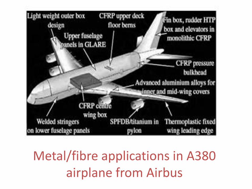
Metal/fibre applications in A380 airplane from Airbus

Functional Graded Material
• FGMs are an advanced class of composite materials where material property like Young’s modulus, Poisson’s ratio, density, etc varies continuously as a function of position , either over thickness or area, depending on the function required of the material.
• Due to the gradual change in material property from one surface to another, it can eliminate inter laminar stress due to sudden change in material property.
• Metal ceramic FGMs are commonly used as a thermal barrier material, where the ceramic surface will resist the temperature and the metal matrix will provide the strength.
• The idea of FGM originated in Japan in 1984 for a space research, in the form of a temperature resistant material that can withstand a temperature of two thousand Kelvin and a thermal gradient of thousand Kelvin with thickness less than ten millimeter[Koizumi and Niino, 1995]
• Functionally graded materials can be used in adverse operating conditions such as high temperature and moisture.
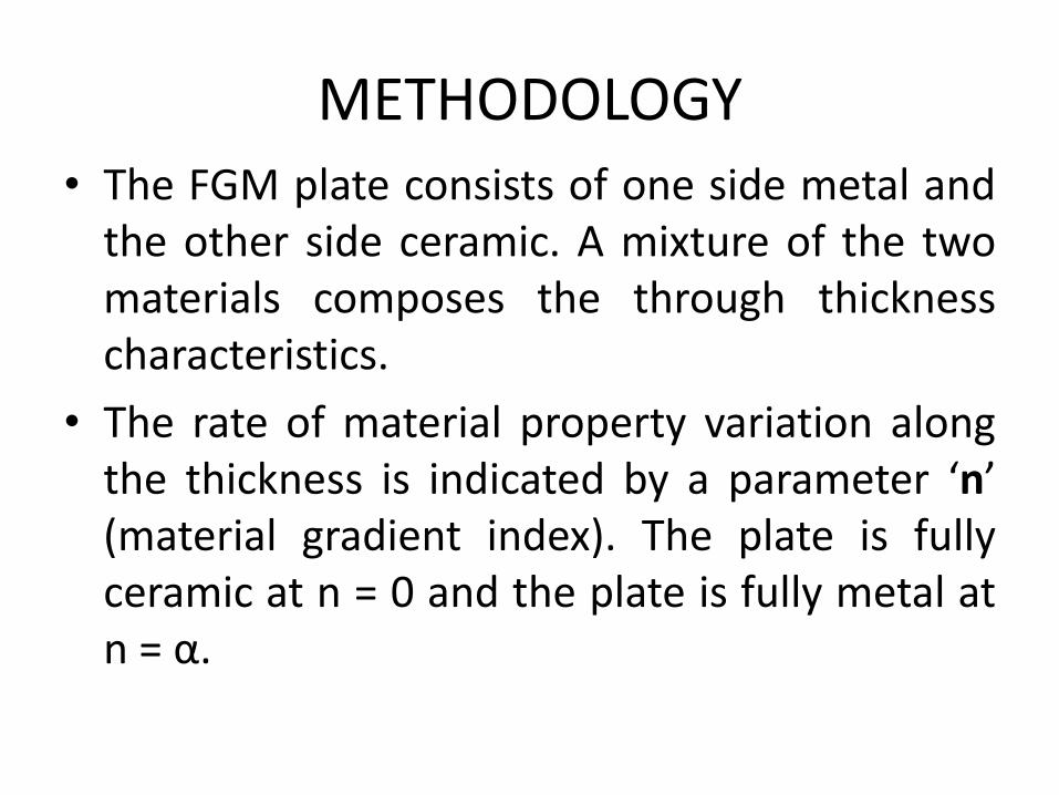
METHODOLOGY • The FGM plate consists of one side metal and
the other side ceramic. A mixture of the two materials composes the through thickness characteristics.
• The rate of material property variation along the thickness is indicated by a parameter ‘n’ (material gradient index). The plate is fully ceramic at n = 0 and the plate is fully metal at n = α.
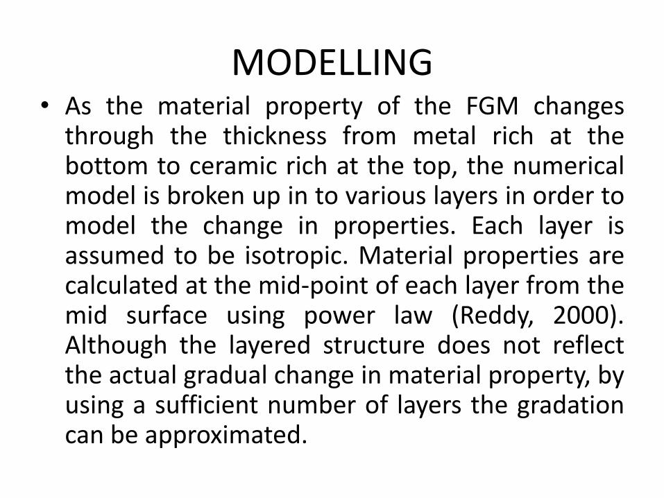
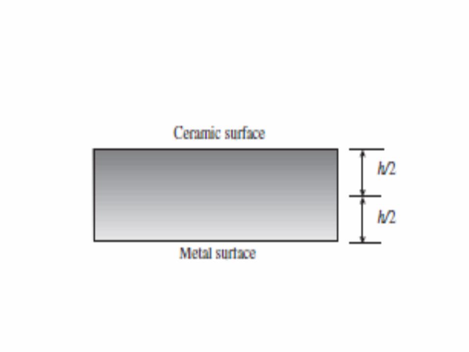
MODELLING • As the material property of the FGM changes
through the thickness from metal rich at the bottom to ceramic rich at the top, the numerical model is broken up in to various layers in order to model the change in properties. Each layer is assumed to be isotropic. Material properties are calculated at the mid-point of each layer from the mid surface using power law (Reddy, 2000). Although the layered structure does not reflect the actual gradual change in material property, by using a sufficient number of layers the gradation can be approximated.
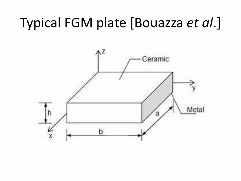
Typical FGM plate [Bouazza et al.]
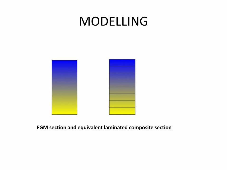
MODELLING
FGM section and equivalent laminated composite section

Smart Structures

A smart structure is basically a system which
has the capability to
• learn about the environment
• process the information in real time
• reduce uncertainty
• generate and execute control actions in a safe and
reliable manner to accomplice the desired
objectives

Objectives of the smart structures
• Ability to sense, measure, process and diagnose at critical locations any change of selected variables and to command appropriate action to preserve structural integrity and continue to perform intended functions.
• The variables are deformation, temperature, pressure, change of state and phase. It may be optical, electrical, magnetic, chemical, or biological.
• The three basic elements to be embedded in a structure is sensor, processor and actuator which enable the structure to behave smartly to maintain the integrity of structures.
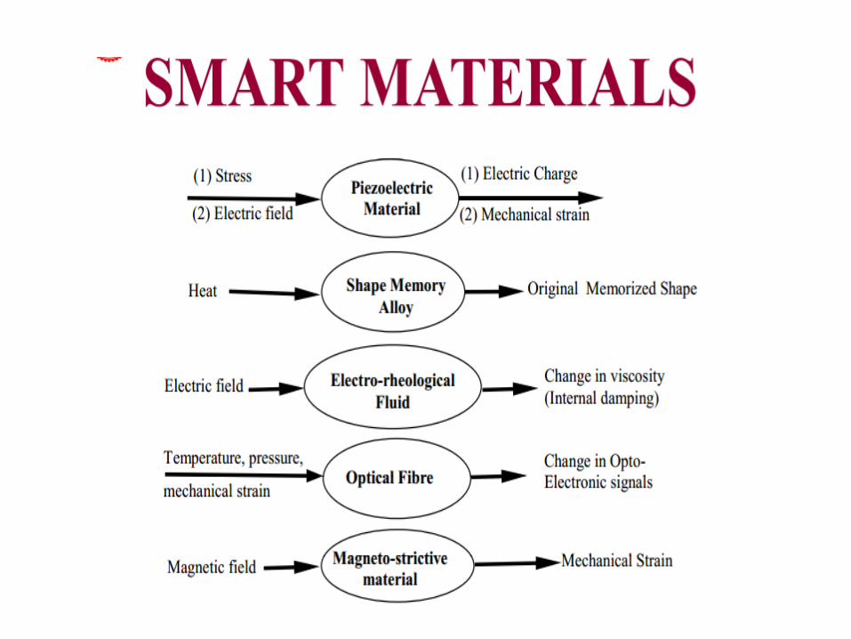
• Smart materials are: Piezoelectric materials that produce a voltage when stress is applied. Since this effect also applies in the reverse manner, a voltage across the sample will produce stress within the sample.

Piezoelectric Materials
• Shape-memory alloys and shape memory polymers are
materials in which large deformation can be induced and
recovered through temperature changes or stress changes
(pseudoelasticity).
• Magnetostrictive materials exhibit change in shape under the
influence of magnetic field and also exhibit change in their
magnetization under the influence of mechanical stress.
• Magnetic shape memory alloys are materials that change
their shape in response to a significant change in the magnetic
field.
• pH-sensitive polymers are materials that change in volume
when the pH of the surrounding medium changes (i.e concrete
with varying pH).
• Halochromic materials are commonly used materials that change their colour as a result of changing acidity. One suggested application is for paints that can change colour to indicate corrosion in the metal underneath them.
• Photomechanical materials change shape under exposure to light.
• Self-healing materials have the intrinsic ability to repair damage due to normal usage, thus expanding the material's lifetime

• Dielectric elastomers (DEs) are smart material systems which produce large strains (up to 300%) under the influence of an external electric field.
• Magnetocaloric materials are compounds that undergo a reversible change in temperature upon exposure to a changing magnetic field.
• Thermoelectric materials are used to build devices that convert temperature differences into electricity and vice-versa.

Nanotechnology

• Nanotechnology is a field that is dominated by developments in basic physics and chemistry research.
• The phenomena on atomic and molecular level are used to provide materials and structures that perform tasks that are not possible using the materials in their typical macroscopic form.

Nanoscale science can be divided into three broad areas
• nanofabrication and
• nano-characterization with typical applications in nano-electronics and life sciences & energy.
• Nanostructures

Nanotechnology can be used for design and construction processes in products that are for:
• Lighter structure
• Stronger structural composites e.g. for bridges
• Low maintenance coating
• Improving pipe joining materials and techniques
• Better properties of cementitious materials
• Reducing the thermal transfer rate of fire retardant and insulation
• Increasing the sound absorption of acoustic absorber
• Increasing the reflectivity of glass.
Applications of nanotechnology in
construction engineering/industry
• Addition of nanoscale materials into cement could improve its performance.
• The dispersion/slurry of amorphous nanosilica is used to improve segregation resistance for self-compacting concrete.
• Addition of small amount of carbon nanotube (1%) by weight could increase both compressive and flexural strength.
• Nano and Microelectrical mechanical systems (MEMS) sensors are used in construction to monitor and/or control the environment condition and the materials/structure performance.
• Advantage of these sensors is their dimension.
• These sensors could be embedded into the structure during the construction process.
• Smart aggregate, a low cost piezoceramic-based multi-functional device, has been applied to monitor early age concrete properties such as moisture, temperature, relative humidity and early age strength development.
• The sensors can also be used to monitor concrete corrosion and cracking.

Carbon Nanotubes
http://onorbit.com/node/825
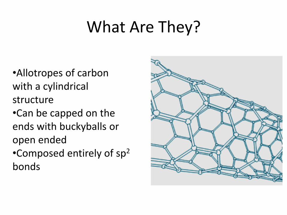
What Are They?
•Allotropes of carbon with a cylindrical structure •Can be capped on the ends with buckyballs or open ended •Composed entirely of sp2 bonds
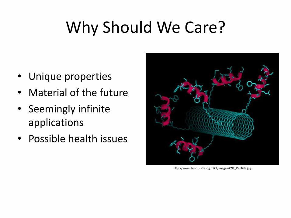
Why Should We Care?
• Unique properties
• Material of the future
• Seemingly infinite applications
• Possible health issues
http://www-ibmc.u-strasbg.fr/ict/images/CNT_Peptide.jpg
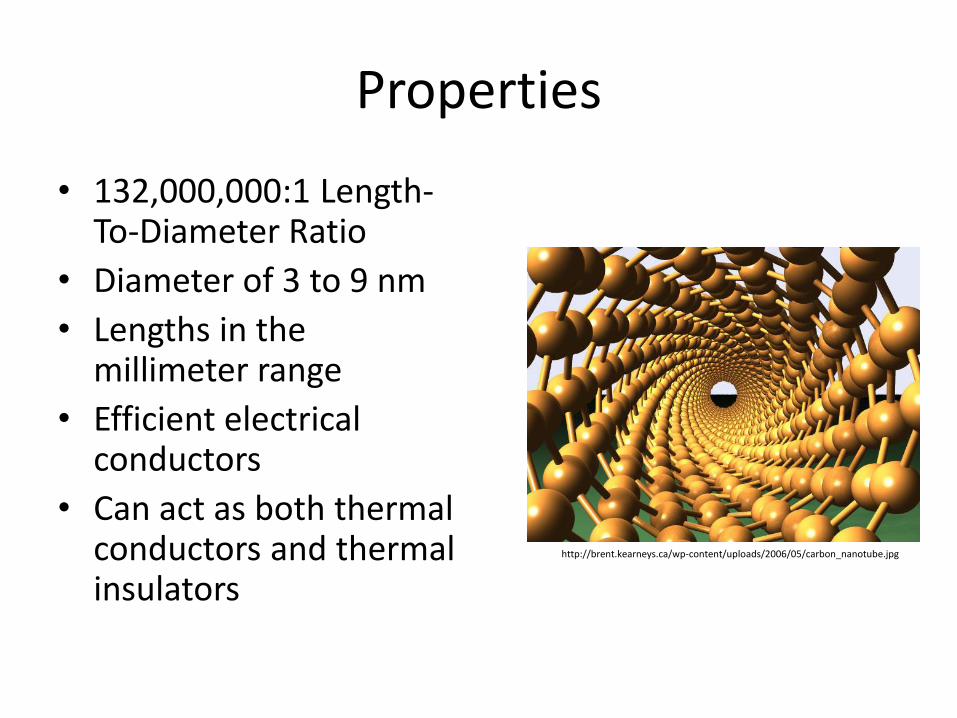
Properties
• 132,000,000:1 Length-To-Diameter Ratio
• Diameter of 3 to 9 nm
• Lengths in the millimeter range
• Efficient electrical conductors
• Can act as both thermal conductors and thermal insulators
http://brent.kearneys.ca/wp-content/uploads/2006/05/carbon_nanotube.jpg

Single-Wall Nanotube (SWNT)
Armchair Zig-Zag

Multi-Walled Nanotubes (MWNT)
• Multiple rolled layers of graphene sheets
• More resistant to chemical changes than SWNTs
http://www.siemens.com/innovation/en/about_fande/corp_technology/partnerships_experts/uc_berkeley.htm
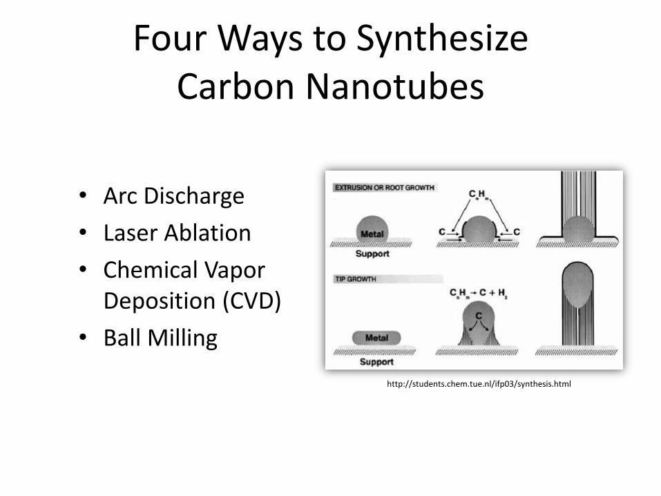
Four Ways to Synthesize Carbon Nanotubes
• Arc Discharge
• Laser Ablation
• Chemical Vapor Deposition (CVD)
• Ball Milling
http://students.chem.tue.nl/ifp03/synthesis.html

Structural Health
Monitoring(SHM)

What is SHM?
• The process of implementing a damage detection and characterization strategy for engineering structures is referred to as Structural Health Monitoring (SHM).
What is Damage?
• Damage is defined as changes to the material and/or geometric properties of a structural system, including changes to the boundary conditions and system connectivity, which adversely affect the system’s performance.

Why Structural Health Monitoring?
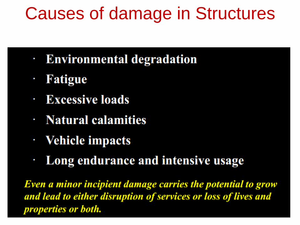
Causes of damage in Structures
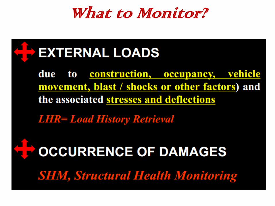
What to Monitor?

• Non descriptive evaluation (NDE) methods including vibration and soft computing i.e. neural network, fuzzy logic are employed to assess the integrity of the structure, including radio graphics, fibre optics, x-rays acoustic emission and ultrasonic techniques.

Mesh Free Finite Element
• Meshfree methods are a particular class of numerical simulation algorithms for the simulation of physical phenomena.
• Traditional simulation algorithms relied on a grid or a mesh, meshfree methods in contrast use the geometry of the simulated object directly for calculations.
• Meshfree methods exist for fluid dynamics as well as for solid mechanics.
• Recent advances on meshfree methods aim at the development of computational tools for automation in modeling and simulations.
• As triangular mesh can be generated automatically, it becomes much easier in re-meshing and hence automation in modeling and simulation.
• Together with stiff models (such as the fully compatible FEM models), one can conveniently bound the solution from both sides.
• This allows easy error estimation for generally complicated problems, as long as a triangular mesh can be generated.

Multiscale Modelling
• Multiscale modelling is the field of solving physical problems which have important features at multiple scales, particularly multiple spatial and (or) temporal scales.
• Multiscale modelling, connecting the hierarchy of scales in materials nano-micro-meso-macro is a dominant trend.
• Embedding a discrete model at one scale e.g., atomistic simulation, simulation of discrete dislocations, simulation of particles or fibers in a matrix, the role of nanopores in concrete into a continuum model at the next higher scale is a challenge where success can yield superior understanding of composites, polycrystals, and porous or cellular materials.
• In operation research, multiscale modeling addresses challenges for decision makers which come from multiscale phenomena across organizational, temporal and spatial scales.
• This theory fuses decision theory and multiscale mathematics and is referred to as Multiscale decission making.
• Application of multiscale modeling methods for the determination of structure and properties of advanced macromolecular materials.
• The purpose of multiscale models is to determine the locally averaged global constitutive behavior of heterogeneous materials taking into account the effect of the microstructure, which may exhibit all kinds of heterogeneity, including evolving cracks.

Earthquake Resistant Design
• Early stage seismic structural design of buildings has been based on representing the earthquake loading effect in terms of static equivalent forces, which are calculated from elastic response spectra that relate the peak ground acceleration (PGA) with the absolute pseudo-acceleration response.
• From the 1990s onward, increasing emphasis has been put on displacement considerations, leading to the development of displacement-based design procedures.
• The maximum relative displacement (or displacement ductility) is the structural response parameter most used for evaluating the inelastic performance of structures.
• The level of structural damage due to earthquakes does not depend only on maximum displacement, and that the cumulative damage resulting from numerous inelastic cycles must be taken into account.
• Resorting to the concept of equivalent (reduced) ductility factors, also known as target ductility.

Spectral Finite Element

• Spectral methods are a class of techniques used in applied mathematics and scientific computing to numerically solve certain differential equations often involving the use of the Fast Fourier Transform.
• The idea is to write the solution of the differential equation as a sum of certain basis functions and then to choose the coefficients in the sum in order to satisfy the differential equation as well as possible.

• Spectral methods and finite element methods are closely related and built on the same ideas the main difference between them is that spectral methods use basis functions that are nonzero over the whole domain, while finite element methods use basis functions that are nonzero only on small subdomains.
• In other words, spectral methods take on a global approach while finite element methods use a local approach.
• Spectral methods have excellent error properties, with the so-called "exponential convergence" being the fastest possible, when the solution is smooth.
• However, there are no known three-dimensional single domain spectral shock capturing results.

• In the finite element community, a method where the degree of the elements is very high or increases as the grid parameter h decreases to zero is sometimes called a spectral element method.
• Spectral methods can be used to solve ordinary differential equations (ODEs), partial differential equations (PDEs) and eigenvalue problems involving differential equations.
• When applying spectral methods to time-dependent PDEs, the solution is typically written as a sum of basis functions with time-dependent coefficients; substituting this in the PDE yields a system of ODEs in the coefficients which can be solved using any numerical method for ODEs.
• Spectral methods are computationally less expensive than finite element methods, but become less accurate for problems with complex geometries and discontinuous coefficients.

Modal Testing
• Experimental modal analysis (EMA) still plays a key role, because it helps the structural dynamicist to reconcile numerical predictions with experimental investigations.
• The use of modern sophisticated FFT analyser with contact and non contact accelerometers (Scanning Laser vibrometers) paves a long way in this directions.
• Three-dimensional digital image correlation (DIC) techniques have come a long way from their conception in the 1980s.
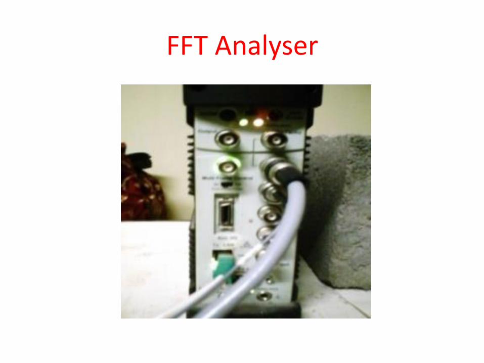
FFT Analyser
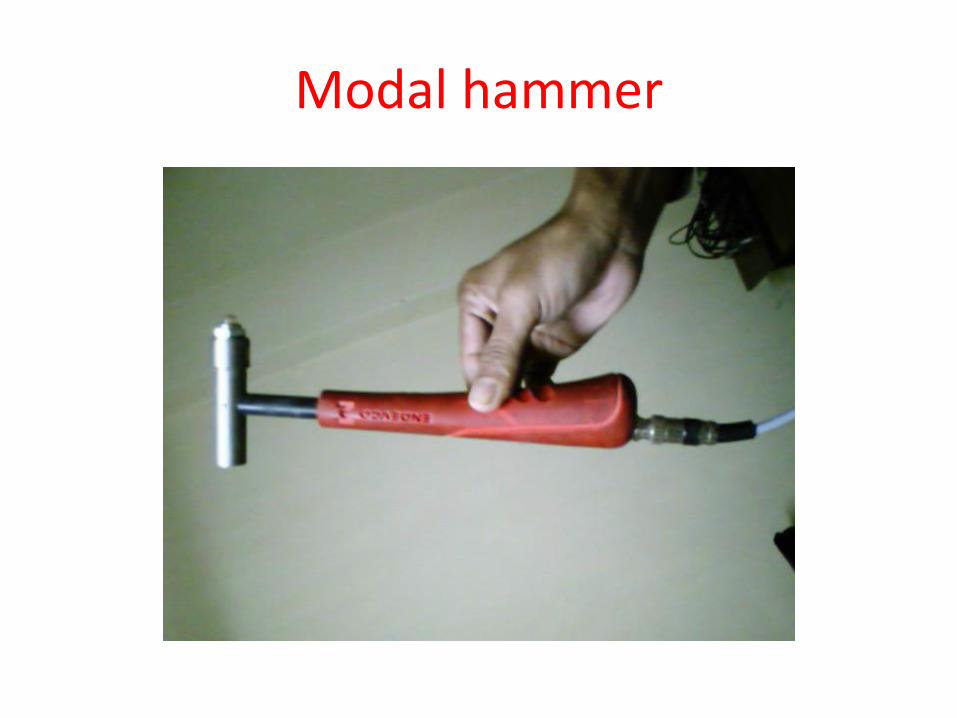
Modal hammer
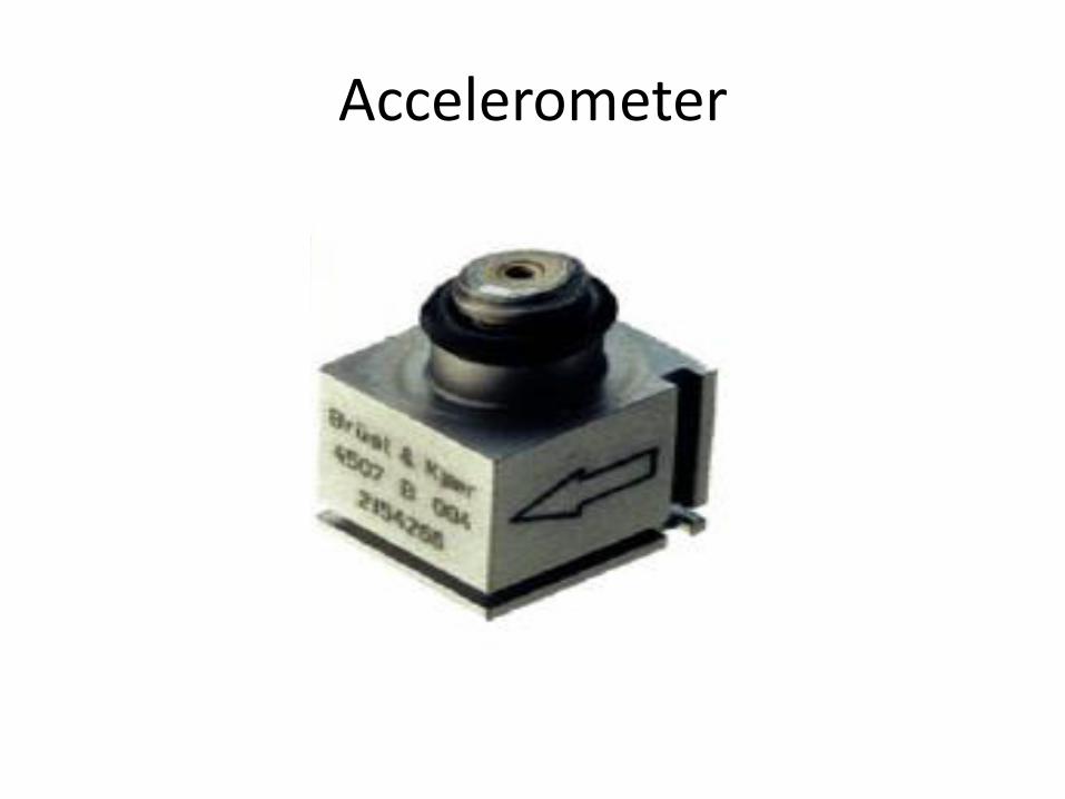
Accelerometer
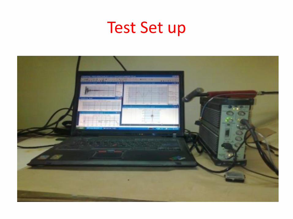
Test Set up
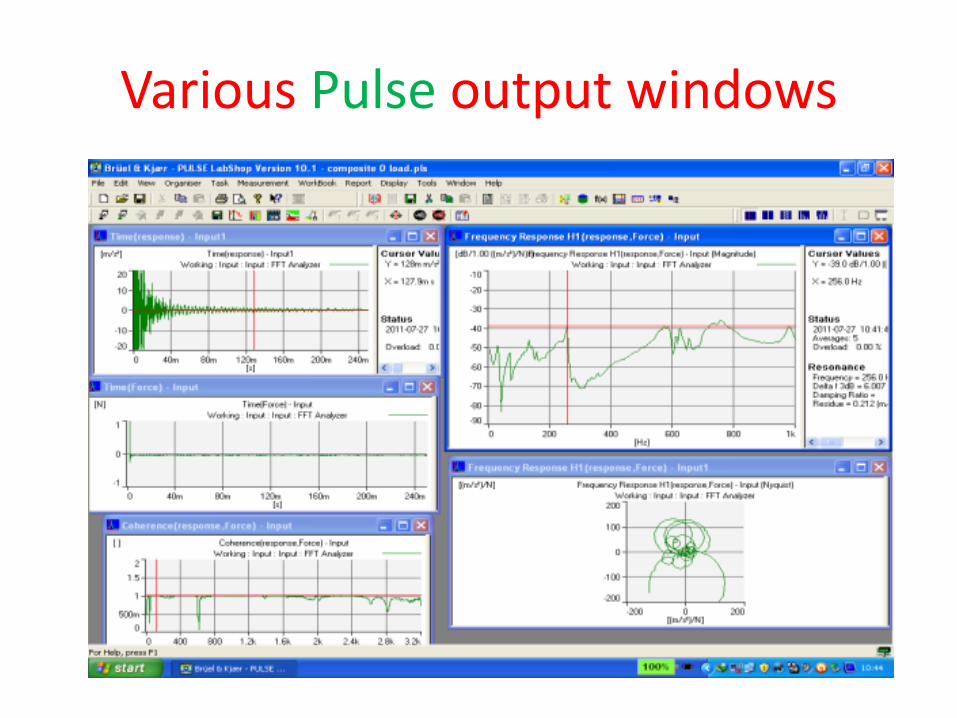
Various Pulse output windows
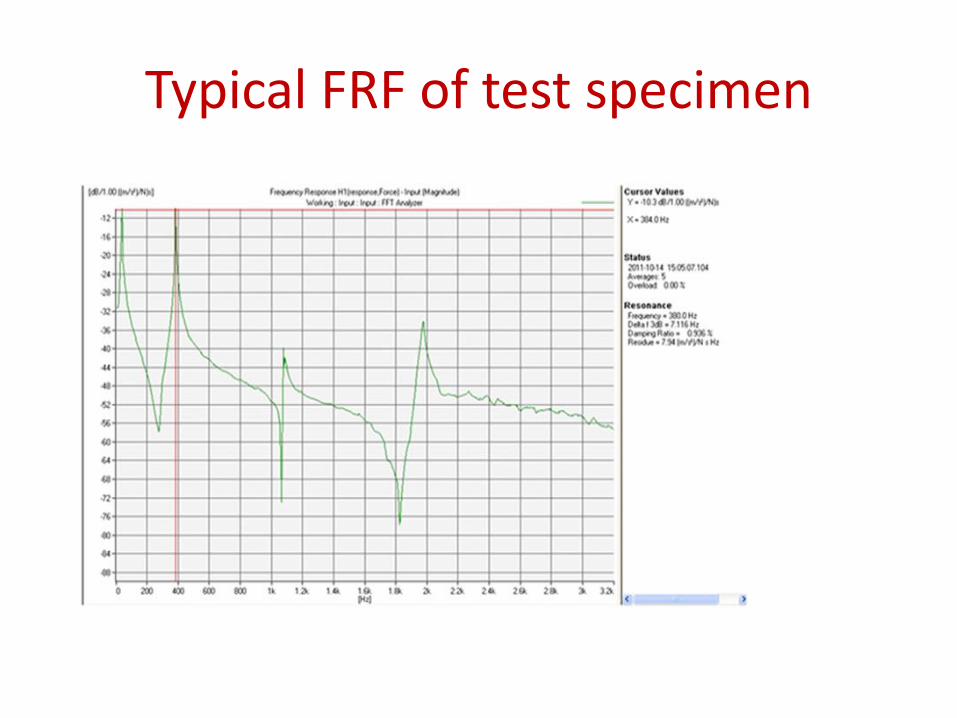
Typical FRF of test specimen

Typical coherence of test specimen

Free vibration of Delaminated Woven Fibre Composite panels
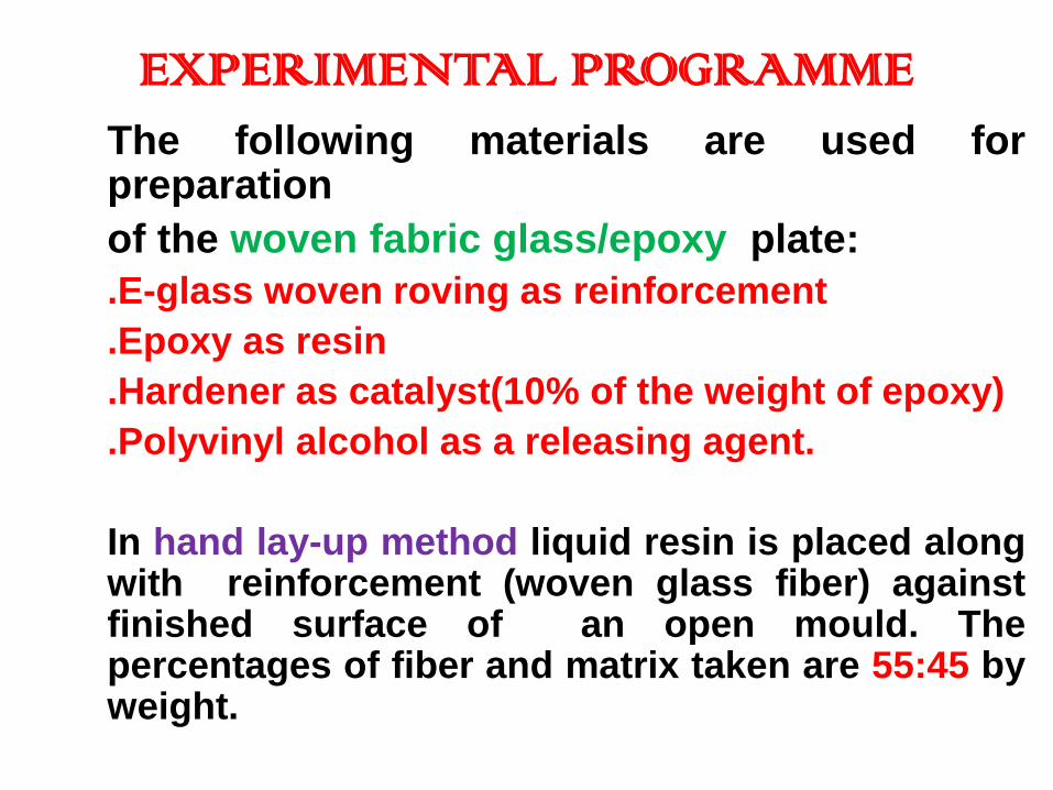
EXPERIMENTAL PROGRAMME The following materials are used for
preparation
of the woven fabric glass/epoxy plate:
.E-glass woven roving as reinforcement
.Epoxy as resin
.Hardener as catalyst(10% of the weight of epoxy)
.Polyvinyl alcohol as a releasing agent.
In hand lay-up method liquid resin is placed along with reinforcement (woven glass fiber) against finished surface of an open mould. The percentages of fiber and matrix taken are 55:45 by weight.
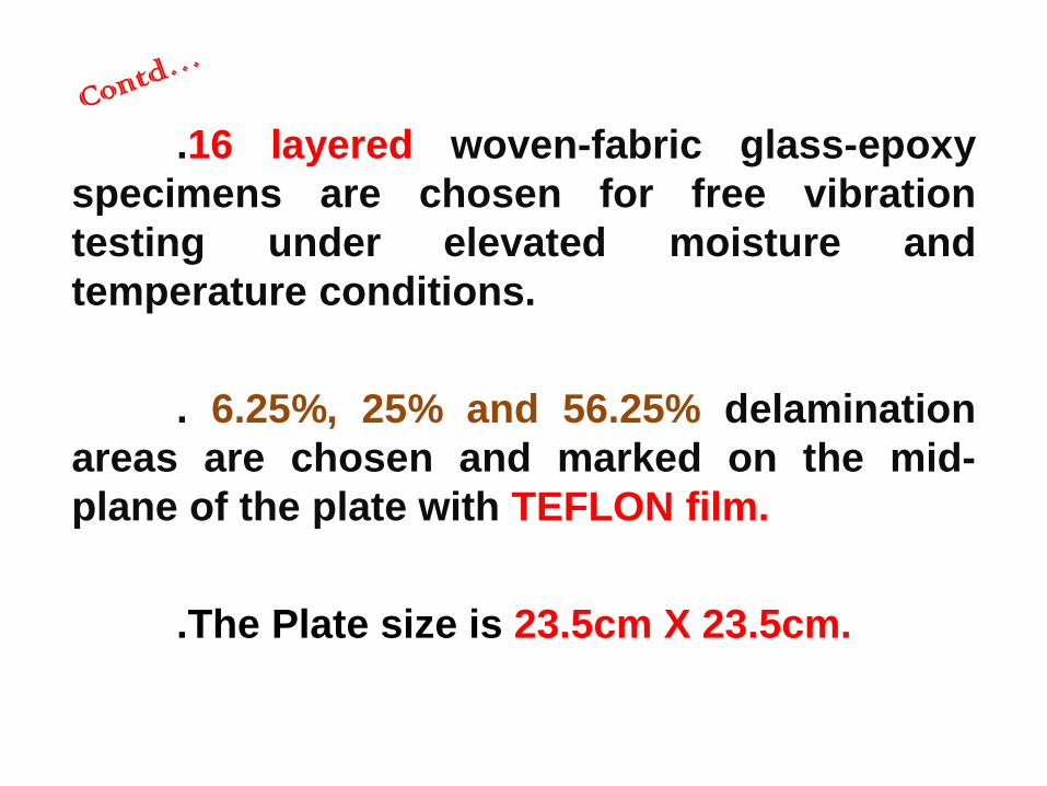
.16 layered woven-fabric glass-epoxy
specimens are chosen for free vibration
testing under elevated moisture and
temperature conditions.
. 6.25%, 25% and 56.25% delamination
areas are chosen and marked on the mid-
plane of the plate with TEFLON film.
.The Plate size is 23.5cm X 23.5cm.
• Reference temperature (300K) and moisture
concentration (0%) have been chosen for the
analysis. Elevated temperature conditions are
chosen to be 325K, 350K and 375K and elevated
moisture concentrations are chosen as 0.25%, 0.5%
and 0.75% for the present analysis.
• Simply Supported(s-s-s-s), Fully Clamped (c-c-c-c),
Two opposite sides clamped and two other sides
simply supported (c-s-c-s), Two opposite sides
clamped and two other sides free (c-f-c-f) boundary
conditions are chosen for the study.
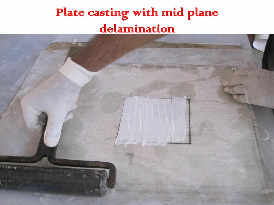
Plate casting with mid plane
delamination
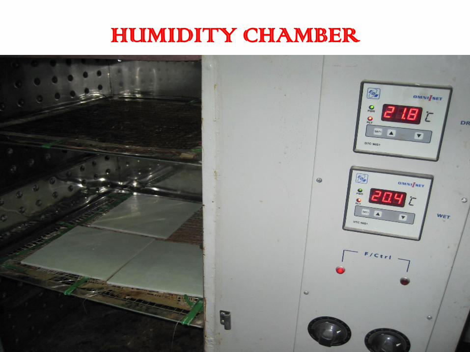
HUMIDITY CHAMBER
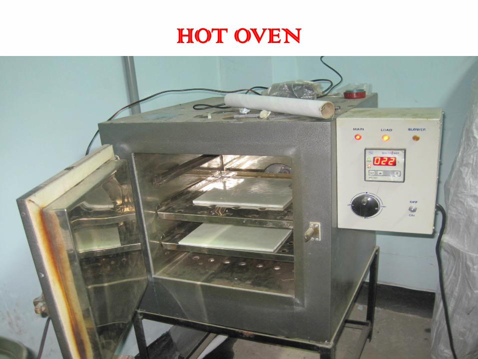
HOT OVEN
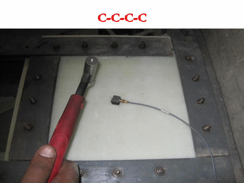
C-C-C-C
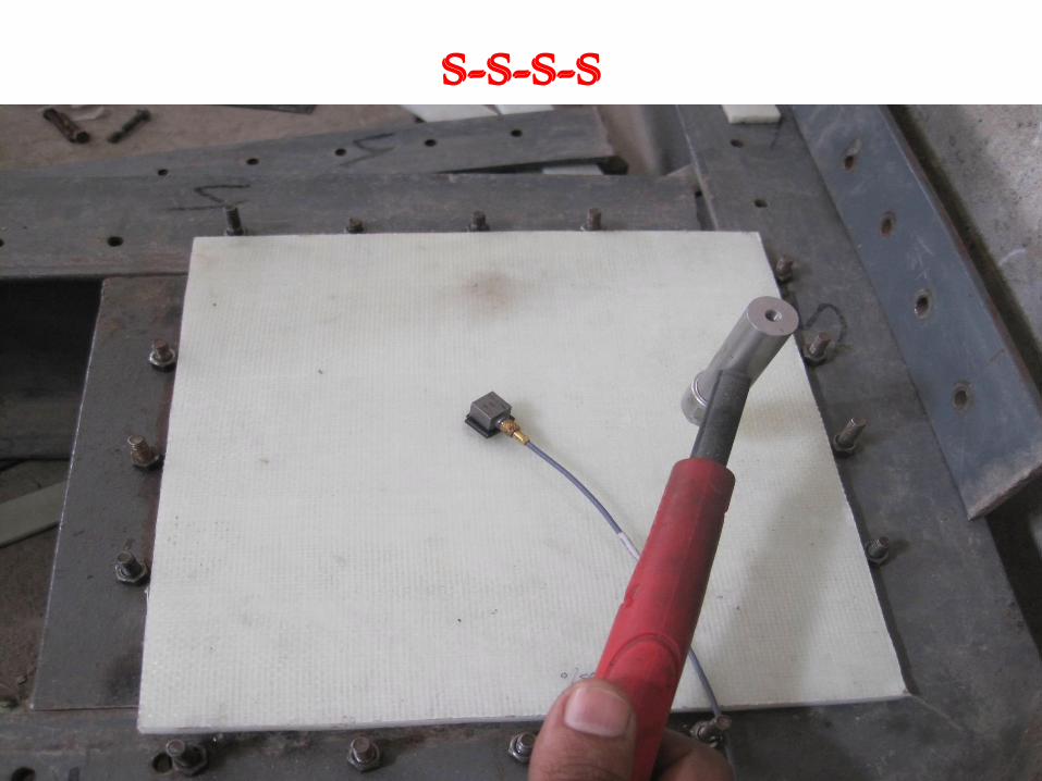
S-S-S-S
C-F-C-F
C-S-C-S
INSTRON 1195

TENSILE MODULUS TESTING
Cont… Fabricated Moulds for curved panels
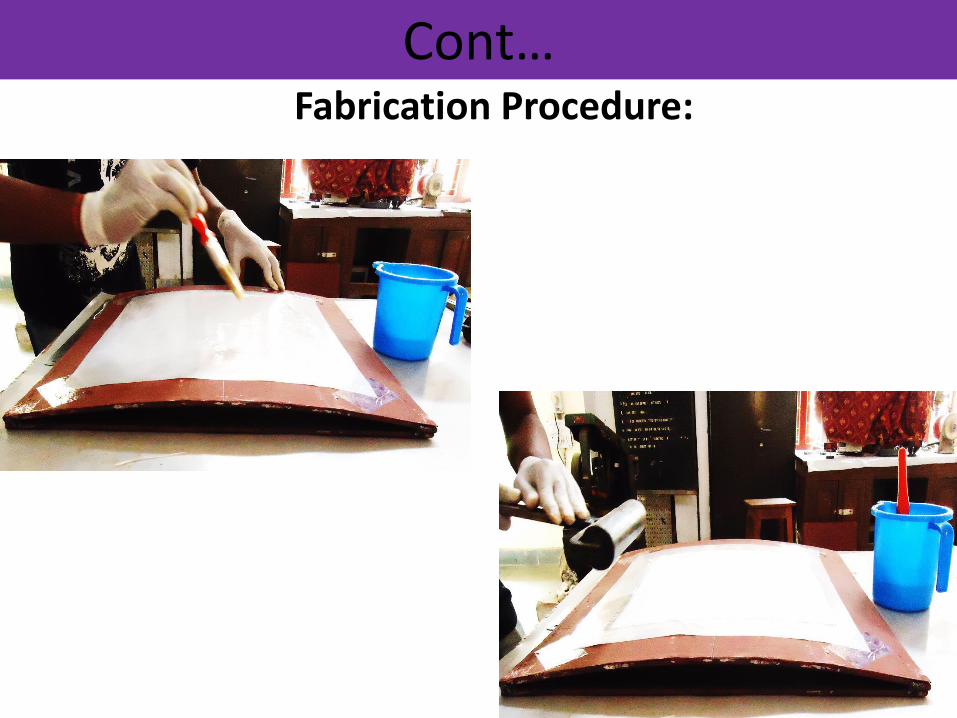
Cont… Fabrication Procedure:
Application of gel coat on
mould releasing sheet
Placing of woven roving
glass fibre on gel coat &
removal of air entrapment
using steel roller
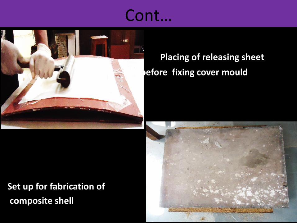
Cont…
Placing of releasing sheet
before fixing cover mould
Set up for fabrication of
composite shell
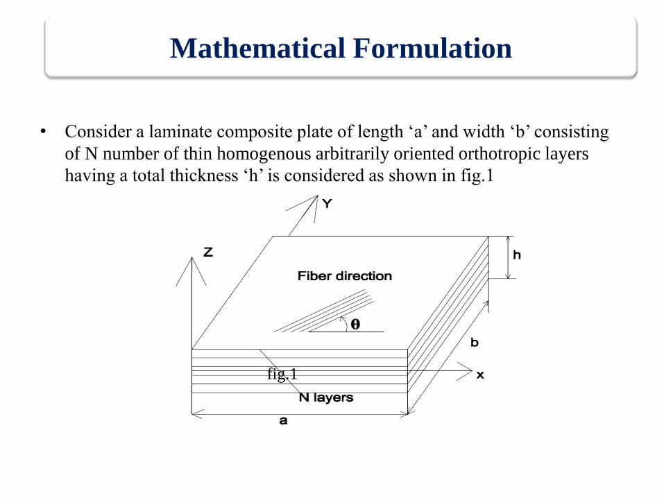
• Consider a laminate composite plate of length ‘a’ and width ‘b’ consisting
of N number of thin homogenous arbitrarily oriented orthotropic layers
having a total thickness ‘h’ is considered as shown in fig.1
Mathematical Formulation
fig.1
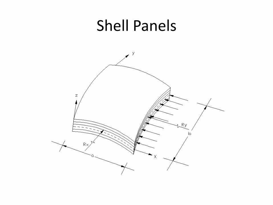
Shell Panels
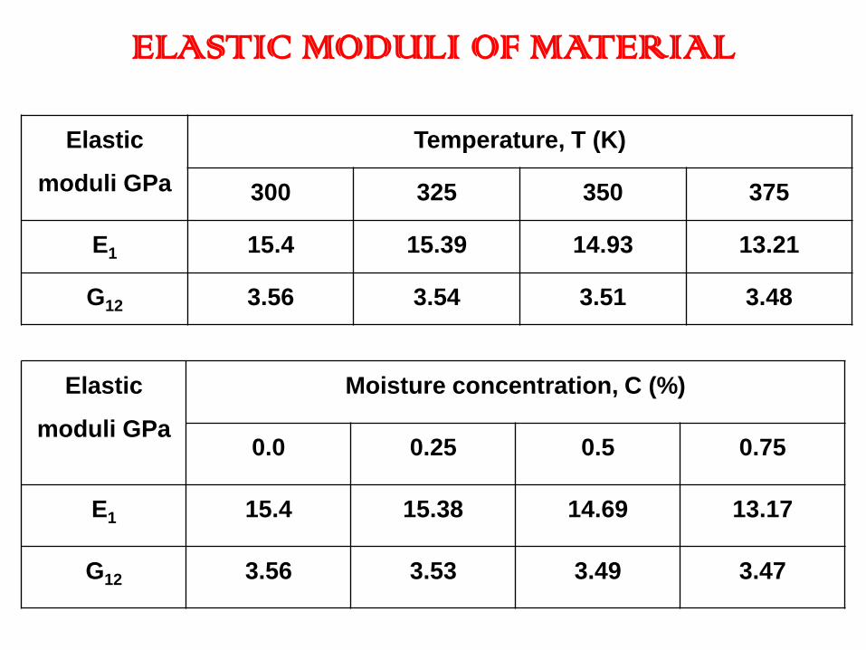
ELASTIC MODULI OF MATERIAL
Elastic
moduli GPa
Moisture concentration, C (%)
0.0 0.25 0.5 0.75
E1 15.4 15.38 14.69 13.17
G12 3.56 3.53 3.49 3.47
Elastic
moduli GPa
Temperature, T (K)
300 325 350 375
E1 15.4 15.39 14.93 13.21
G12 3.56 3.54 3.51 3.48

EFFECT OF TEMPERATURE ON
FUNDAMENTAL FREQUENCY
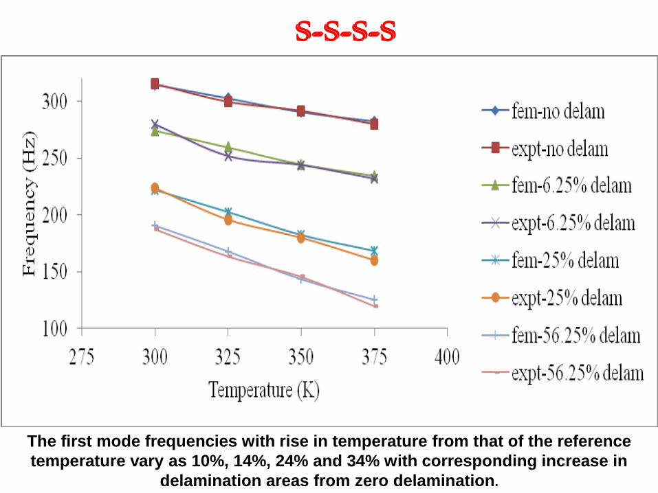
S-S-S-S
The first mode frequencies with rise in temperature from that of the reference
temperature vary as 10%, 14%, 24% and 34% with corresponding increase in
delamination areas from zero delamination.
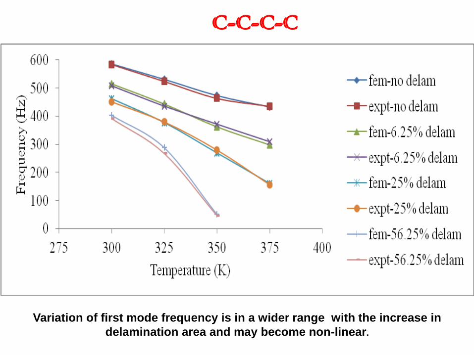
C-C-C-C
Variation of first mode frequency is in a wider range with the increase in
delamination area and may become non-linear.
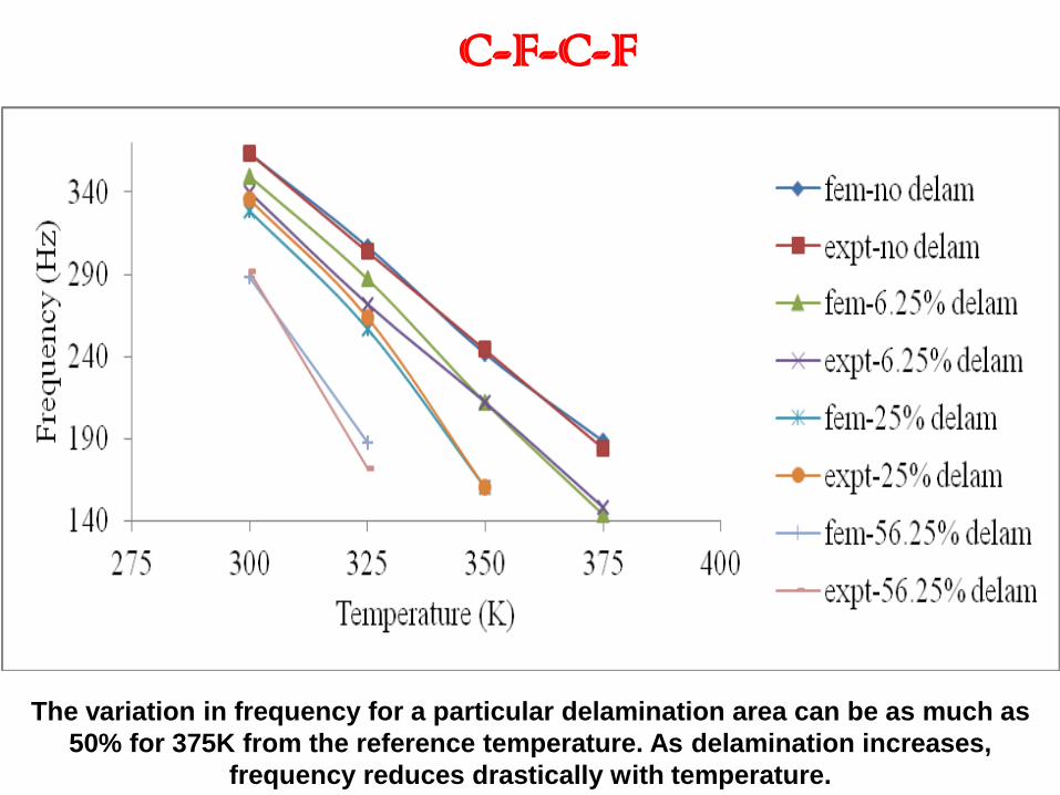
C-F-C-F
The variation in frequency for a particular delamination area can be as much as
50% for 375K from the reference temperature. As delamination increases,
frequency reduces drastically with temperature.
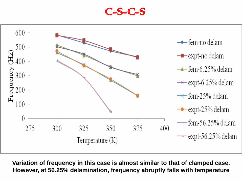
C-S-C-S
Variation of frequency in this case is almost similar to that of clamped case.
However, at 56.25% delamination, frequency abruptly falls with temperature

EFFECT OF MOISTURE ON
FUNDAMENTAL FREQUENCY
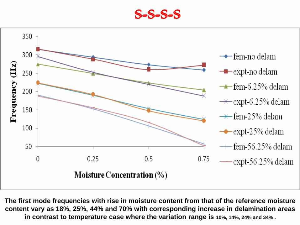
S-S-S-S
The first mode frequencies with rise in moisture content from that of the reference moisture
content vary as 18%, 25%, 44% and 70% with corresponding increase in delamination areas
in contrast to temperature case where the variation range is 10%, 14%, 24% and 34% .
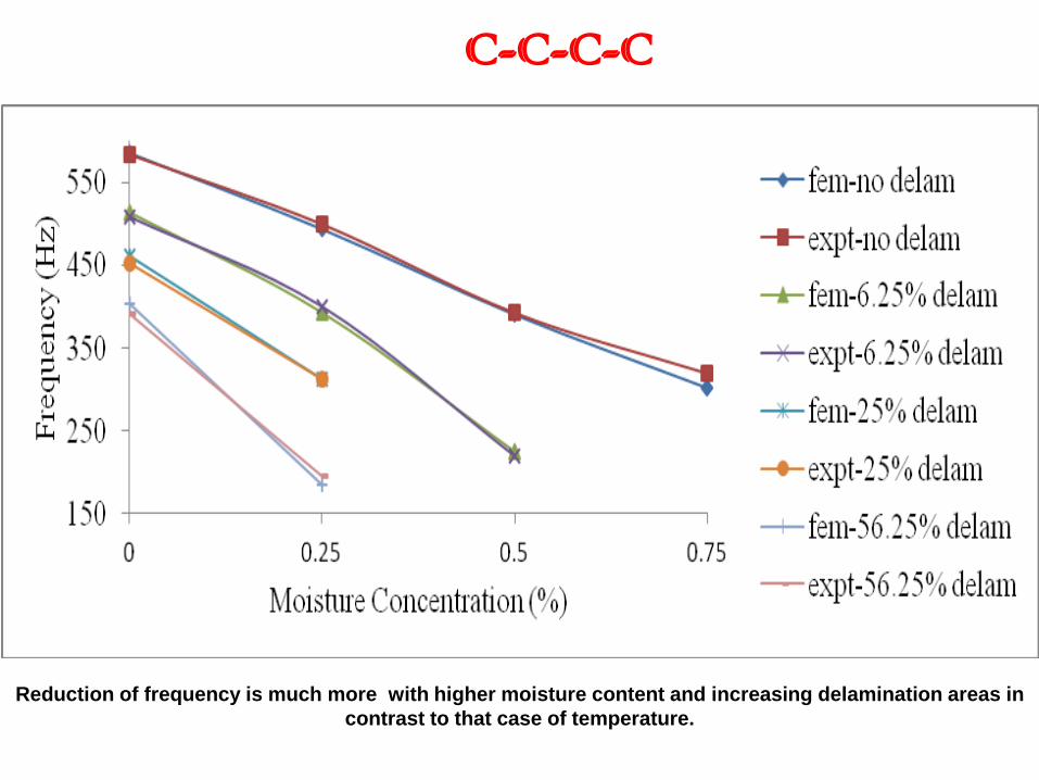
C-C-C-C
Reduction of frequency is much more with higher moisture content and increasing delamination areas in
contrast to that case of temperature.
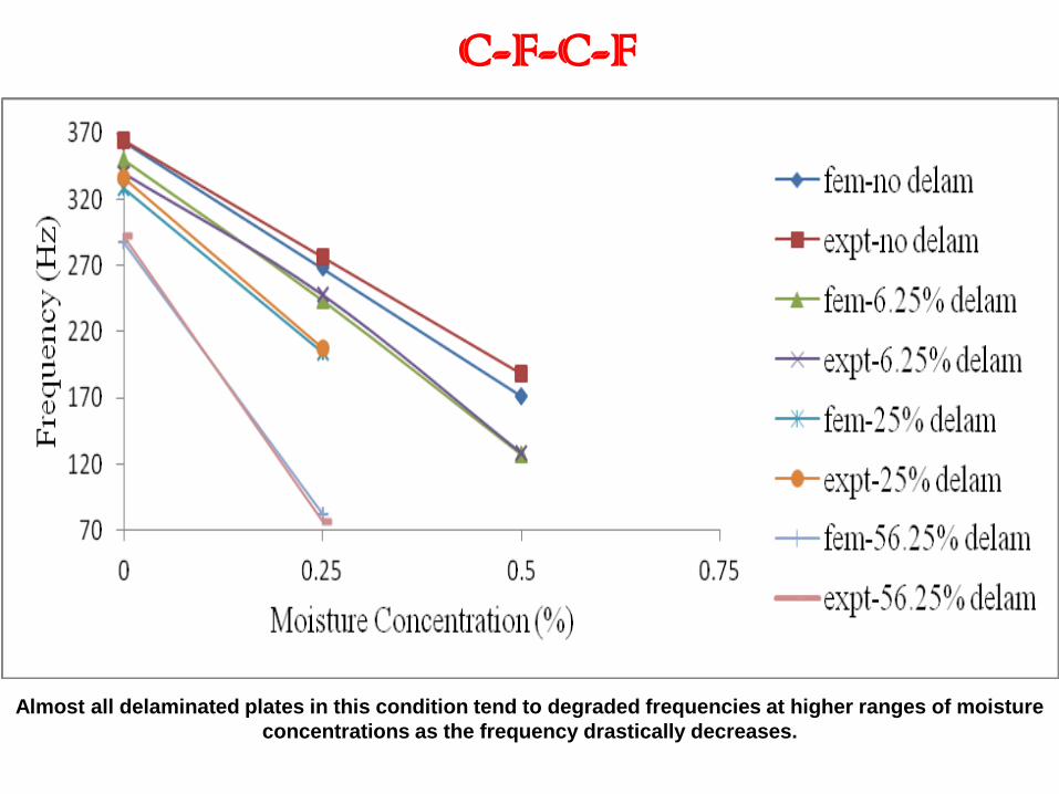
C-F-C-F
Almost all delaminated plates in this condition tend to degraded frequencies at higher ranges of moisture
concentrations as the frequency drastically decreases.
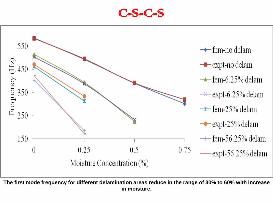
C-S-C-S
The first mode frequency for different delamination areas reduce in the range of 30% to 60% with increase
in moisture.
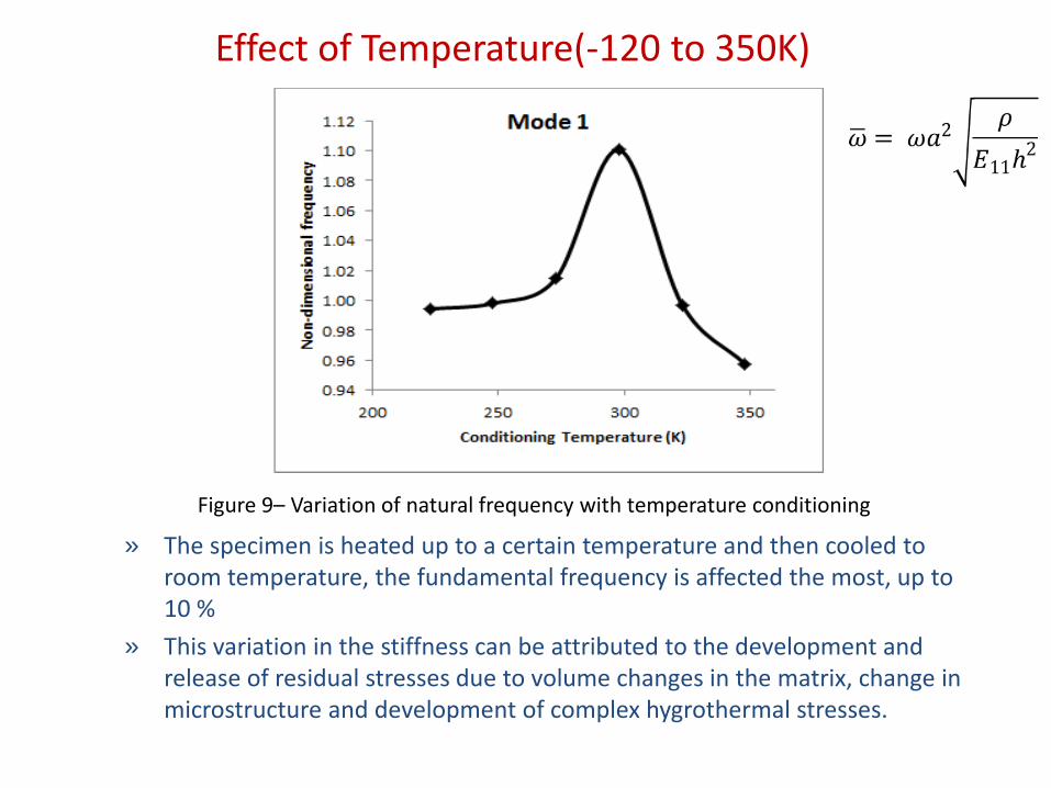
Effect of Temperature(-120 to 350K)
» The specimen is heated up to a certain temperature and then cooled to room temperature, the fundamental frequency is affected the most, up to 10 %
» This variation in the stiffness can be attributed to the development and release of residual stresses due to volume changes in the matrix, change in microstructure and development of complex hygrothermal stresses.
Figure 9– Variation of natural frequency with temperature conditioning
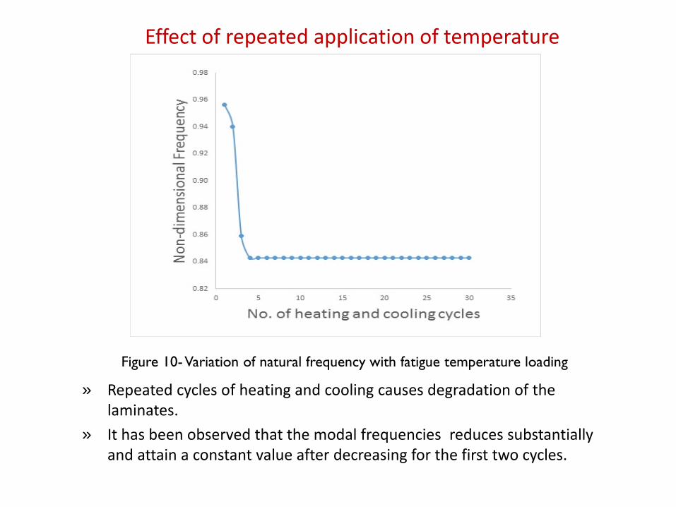
Effect of repeated application of temperature
» Repeated cycles of heating and cooling causes degradation of the laminates.
» It has been observed that the modal frequencies reduces substantially and attain a constant value after decreasing for the first two cycles.
Figure 10- Variation of natural frequency with fatigue temperature loading

Effect of Hygrothermal Condition
• With increase in moisture concentration the modal frequencies of CFRP plates is observed to decrease as seen in Figure .
1.9
1.9
1.9
2.0
2.0
2.0
2.0
2.0
2.1
2.1
2.1
0.00 0.10 0.20 0.30 0.40 0.50 0.60
No
n-d
imen
sio
nal
freq
uen
cy
Moisture concentration (%)
Figure – Variation of non-dimensional frequencies of CFRP plates with moisture concentration
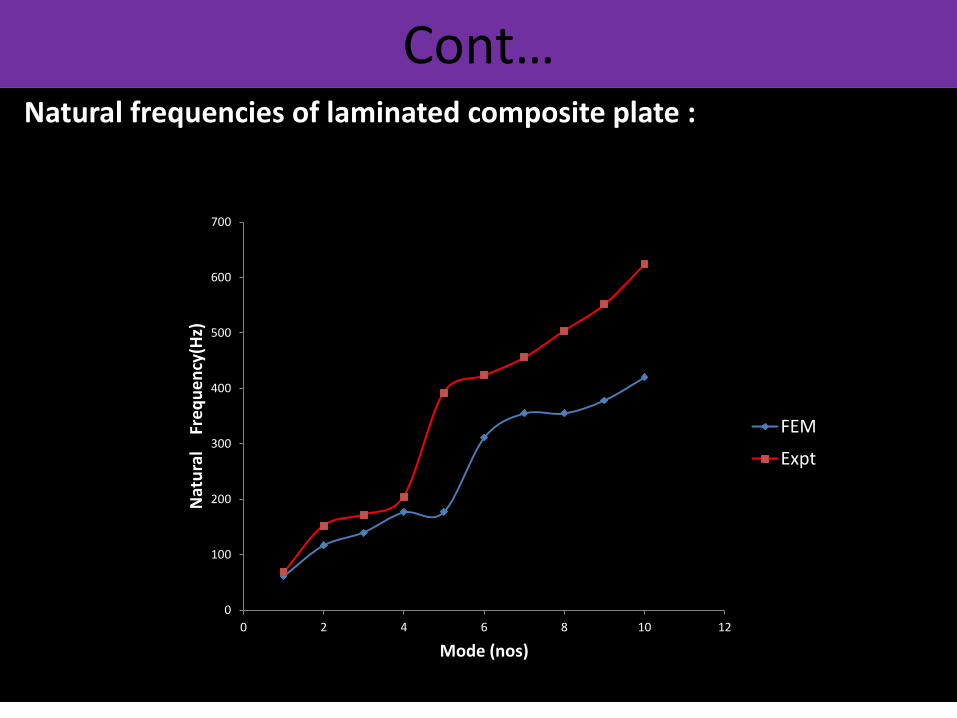
Cont… Natural frequencies of laminated composite plate :
0
100
200
300
400
500
600
700
0 2 4 6 8 10 12
Nat
ura
l F
req
ue
ncy
(Hz)
Mode (nos)
FEM
Expt

Cont… Natural frequencies of laminated cylindrical shell with Ry=0.910
0
100
200
300
400
500
600
0 1 2 3 4 5 6 7 8 9
Nat
ura
l F
req
ue
ncy
(Hz)
Mode(nos)
FEM
Expt
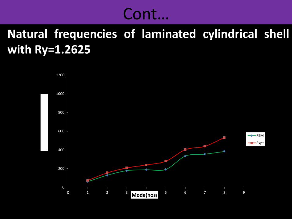
Cont… Natural frequencies of laminated cylindrical shell with Ry=1.2625
0
200
400
600
800
1000
1200
0 1 2 3 4 5 6 7 8 9
Nat
ura
l F
req
ue
ncy
(Hz)
Mode(nos)
FEM
Expt
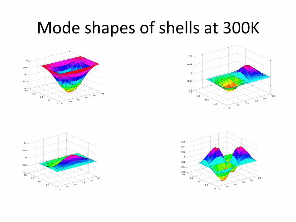
Mode shapes of shells at 300K
00.1
0.20.3
0.40.5
0
0.2
0.4
0.6
0.8-0.2
-0.15
-0.1
-0.05
0
00.1
0.20.3
0.40.5
0
0.2
0.4
0.6
0.8-0.1
-0.05
0
0.05
0.1
00.1
0.20.3
0.40.5
0
0.2
0.4
0.6
0.8-0.1
-0.05
0
0.05
0.1
00.1
0.20.3
0.40.5
0
0.2
0.4
0.6
0.8-0.06
-0.04
-0.02
0
0.02
0.04
0.06
00.1
0.20.3
0.40.5
0
0.2
0.4
0.6
0.8-0.2
-0.15
-0.1
-0.05
0
00.1
0.20.3
0.40.5
0
0.2
0.4
0.6
0.8-0.1
-0.05
0
0.05
0.1
00.1
0.20.3
0.40.5
0
0.2
0.4
0.6
0.8-0.1
-0.05
0
0.05
0.1
00.1
0.20.3
0.40.5
0
0.2
0.4
0.6
0.8-0.06
-0.04
-0.02
0
0.02
0.04
0.06
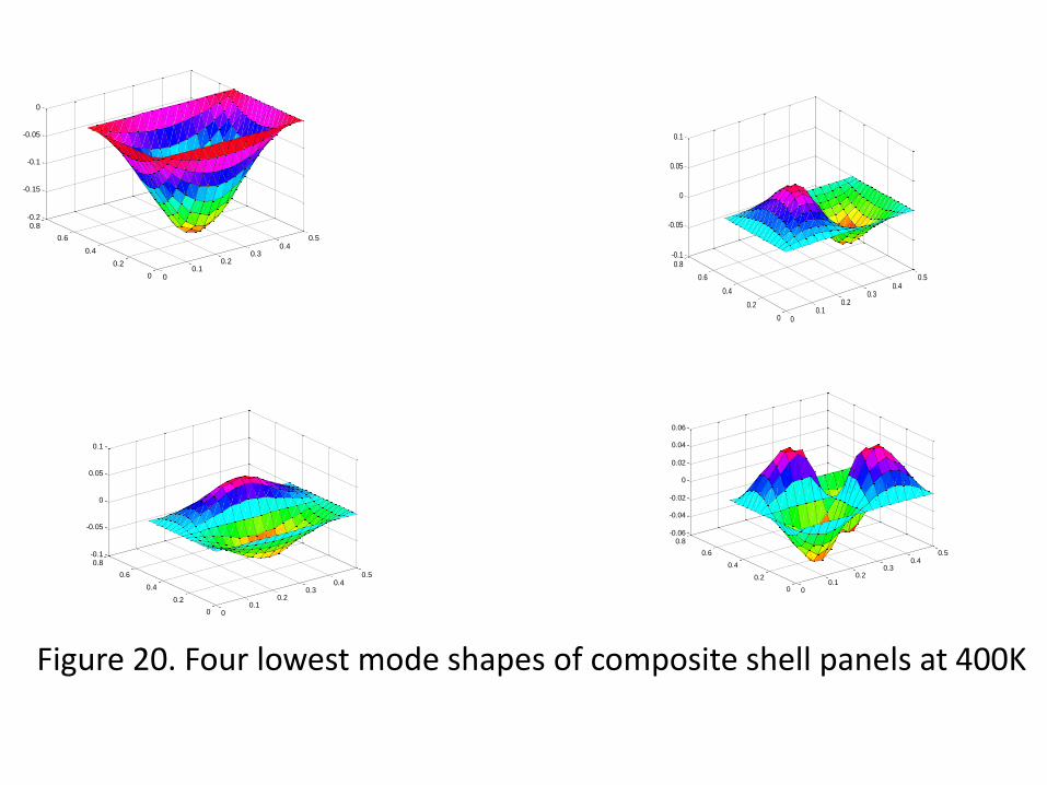
Figure 20. Four lowest mode shapes of composite shell panels at 400K
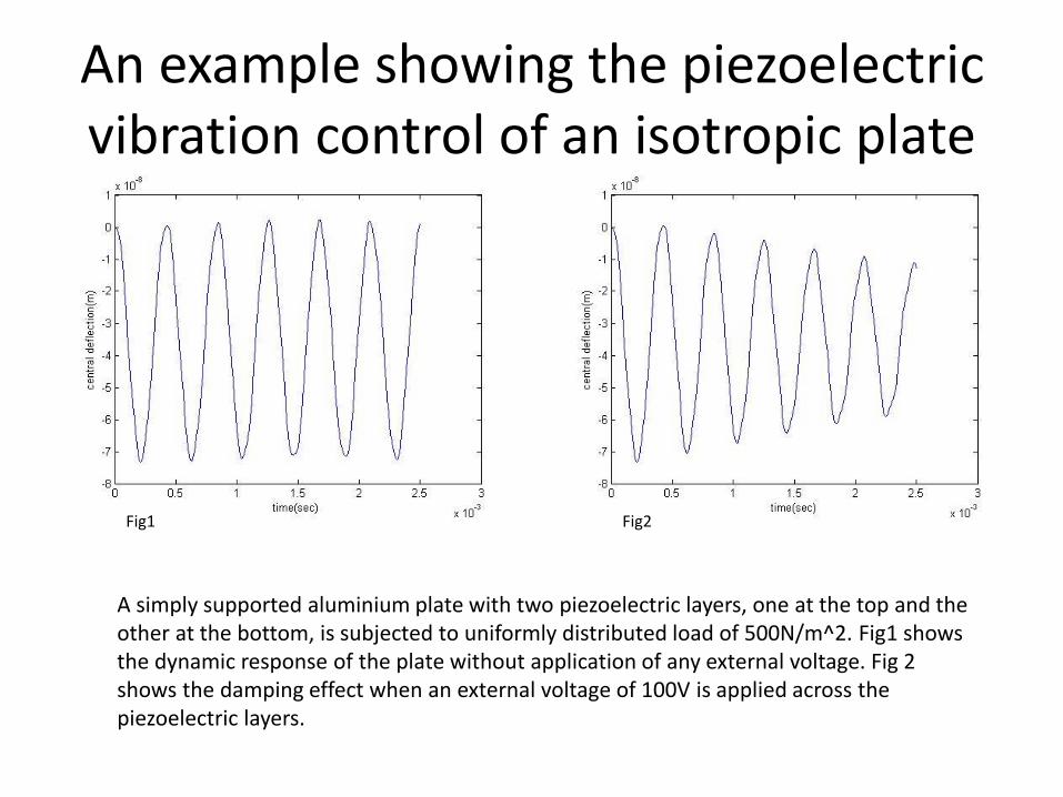
An example showing the piezoelectric vibration control of an isotropic plate
Fig1 Fig2
A simply supported aluminium plate with two piezoelectric layers, one at the top and the other at the bottom, is subjected to uniformly distributed load of 500N/m^2. Fig1 shows the dynamic response of the plate without application of any external voltage. Fig 2 shows the damping effect when an external voltage of 100V is applied across the piezoelectric layers.
• In the present work, some of the current developments in solid
mechanics engineering is discussed with a focus to new materials,
type of structural elements including plates and shell panels.
• From the present numerical studies, it can be concluded that
vibration behavior of the laminated plates is greatly influenced by
the geometry, material, ply lay up, temperature, moisture,
delamination, curvature, orientation, and type of materials.
• It is observed that the first and fourth mode shapers are not much
affected by the increase in temperature. However, for second and
third modes, the convexity and concavity changes are observed due
to increase of temperature, possibly due to change of modes.
• So designer has to be cautions while dealing with
structures subjected to dynamic loading. This can be
used in tailoring during design of composite
structures.
• The vibration results can be used as design aids for
dynamic design of composite structures
• The modal test results can be used as a tool for
structural health monitoring of structures including
location of damage in composites
References
• C.W. Bert and B. L. Mayberry, Free vibrations of unsymmetrically laminated isotropic plates with
clamped edges, J. Composite Materials, 3, (1969), 282-293.
• R.R. Clary and P. A. Cooper, Vibration characterstics of Aluminium plates Reinforced with Boron-
Epoxy composite material, Journal of Composite Materials, 7 (1973), 348-365.
• P. Cawley and R. D. Adams, The Predicted and Experimental Natural Modes of Free-Free CFRP
plates, Journal of Composite Materials,12(1978),336-347.
• E. F. Crawley, The Natural Modes of Graphite/Epoxy Cantilever Plates and Shells, Journal of
Composite Materials, 13(1979), 195-205.
• G.B. Chai, Free vibration of generally laminated composite plates with various edge support
conditions, Composite Structures, 29 (1994) ,249-258
• A.B. Stanbridg and D.J. Ewins, Modal testing using a scanning laser Doppler vibrometer,
Mechanical Systems and Signal Processing 13 (1999) 255–270.
• S. Chakraborty, M. Mukhopadhyay and A. R. Mohanty, Free Vibrational Responses of FRP
Composite Plates: Experimental and Numerical Studies, Journal of Reinforced Plastics and
Composite, 19(2000), 535-551.
• V. Tita, J. Carvalho and J. Lirani, A Procedure to Estimate the Dynamic Damped
Behavior of Fiber Reinforced Composite Beams Submitted to Flexural Vibrations,
Materials Research, 4 (2001), 315-321.
• A. Mahmood, X. Wang and C. Zhou, Modelling strategies of 3D woven
composites: A review, Composite Structures, 93, (2011), 1947-1963.
• L. Xu , R. Wang, S. Zhang and Y. Liu , Vibration characteristics of glass
fabric/epoxy composites with different woven structures, Journal of Composite
Material, 45(2011), 1069-1076.
• K Mahesh Dutt and Dr.H.K.Shivanand, An experimental approach to free vibration
response of carbon composite laminates, journal of Advanced Engineering &
Applications, (2011), 66-68.
• F. Ju, H.P. Lee and K.H. Lee, Finite element analysis of free vibration of
delaminated composite plate. Composite Engineering, 5(1995), 195-209.
• S. K. Sahu and P. K. Datta, Dynamic stability of laminated composite curved panels
with cutouts, J of Engg Mech, ASCE 129 (11) (2003) 1245-1252.

Element details
• In the present investigation, an eight noded two dimensional
quadratic isoparametric element having five degrees of
freedom (u, v, w, x, y) per node is chosen.
• The displacement field may be assumed in the form
• The overall stiffness and mass matrices are obtained by
assembling the corresponding element matrices.
The following constituent materials are used for fabricating
the woven fabric glass/epoxy fiber plate:
• E-glass woven roving as reinforcement
• Epoxy as resin
• Hardener as catalyst(10% of the weight of epoxy)
• Polyvinyl alcohol as a releasing agent.
In hand lay-up method liquid resin is placed along with reinforcement (woven glass fiber) against finished surface of an open mould. The percentages of fiber and matrix taken are 50:50 in weight.
Experimental Programme
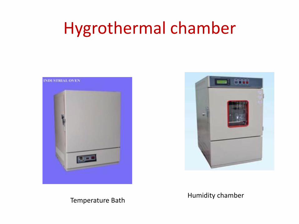
Hygrothermal chamber
Humidity chamber Temperature Bath
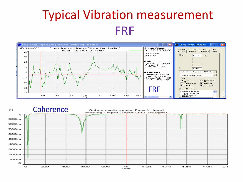
Typical Vibration measurement FRF
FRF
Coherence
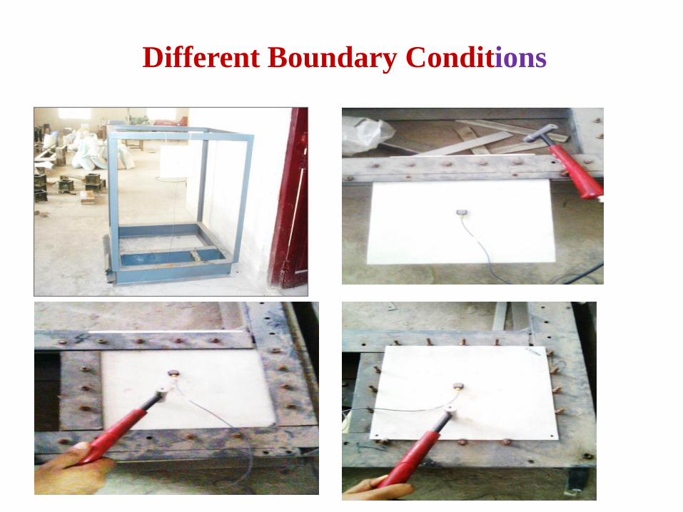
Different Boundary Conditions
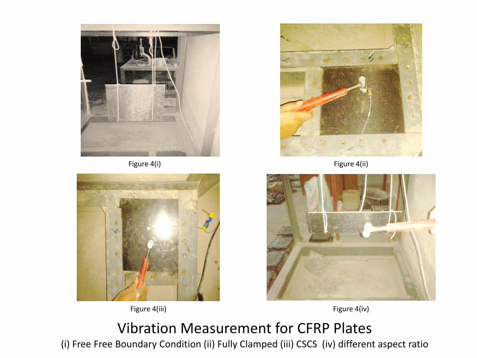
Figure 4(i) Figure 4(ii)
Figure 4(iii) Figure 4(iv)
Vibration Measurement for CFRP Plates (i) Free Free Boundary Condition (ii) Fully Clamped (iii) CSCS (iv) different aspect ratio

Figure 8– Variation of natural frequency with boundary conditions.
Effect of Boundary Conditions
0
200
400
600
800
1000
1200
1400
1600
1800
2000
1 2 3 4
Fre
qu
ecy
(H
z)
Modes
CFFF
FFFF
SSSS
CSCS
CCCC
» It is observed that the modal frequencies for various modes are lowest in case of cantilever boundary conditions.
» The modal frequencies are found to be maximum for fully clamped condition followed by CSCS, SSSS and FFFF in decreasing order.
» The frequencies in case of CSCS boundary condition is more closer to that of fully clamped condition as compared to simply supported boundary condition.
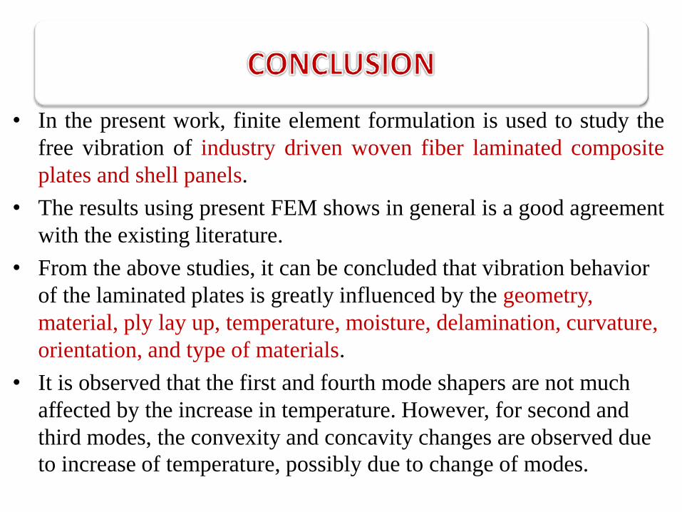
• In the present work, finite element formulation is used to study the
free vibration of industry driven woven fiber laminated composite
plates and shell panels.
• The results using present FEM shows in general is a good agreement
with the existing literature.
• From the above studies, it can be concluded that vibration behavior
of the laminated plates is greatly influenced by the geometry,
material, ply lay up, temperature, moisture, delamination, curvature,
orientation, and type of materials.
• It is observed that the first and fourth mode shapers are not much
affected by the increase in temperature. However, for second and
third modes, the convexity and concavity changes are observed due
to increase of temperature, possibly due to change of modes.

• So designer has to be cautions while dealing with
structures subjected to dynamic loading. This can be
used in tailoring during design of composite
structures.
• The vibration results can be used as design aids for
dynamic design of composite structures
• The modal test results can be used as a tool for
structural health monitoring of structures including
location of damage in composites

References
• C.W. Bert and B. L. Mayberry, Free vibrations of unsymmetrically laminated isotropic plates with
clamped edges, J. Composite Materials, 3, (1969), 282-293.
• R.R. Clary and P. A. Cooper, Vibration characterstics of Aluminium plates Reinforced with Boron-
Epoxy composite material, Journal of Composite Materials, 7 (1973), 348-365.
• P. Cawley and R. D. Adams, The Predicted and Experimental Natural Modes of Free-Free CFRP
plates, Journal of Composite Materials,12(1978),336-347.
• E. F. Crawley, The Natural Modes of Graphite/Epoxy Cantilever Plates and Shells, Journal of
Composite Materials, 13(1979), 195-205.
• G.B. Chai, Free vibration of generally laminated composite plates with various edge support
conditions, Composite Structures, 29 (1994) ,249-258
• A.B. Stanbridg and D.J. Ewins, Modal testing using a scanning laser Doppler vibrometer,
Mechanical Systems and Signal Processing 13 (1999) 255–270.
• S. Chakraborty, M. Mukhopadhyay and A. R. Mohanty, Free Vibrational Responses of FRP
Composite Plates: Experimental and Numerical Studies, Journal of Reinforced Plastics and
Composite, 19(2000), 535-551.

• V. Tita, J. Carvalho and J. Lirani, A Procedure to Estimate the Dynamic Damped
Behavior of Fiber Reinforced Composite Beams Submitted to Flexural Vibrations,
Materials Research, 4 (2001), 315-321.
• A. Mahmood, X. Wang and C. Zhou, Modelling strategies of 3D woven
composites: A review, Composite Structures, 93, (2011), 1947-1963.
• L. Xu , R. Wang, S. Zhang and Y. Liu , Vibration characteristics of glass
fabric/epoxy composites with different woven structures, Journal of Composite
Material, 45(2011), 1069-1076.
• K Mahesh Dutt and Dr.H.K.Shivanand, An experimental approach to free vibration
response of carbon composite laminates, journal of Advanced Engineering &
Applications, (2011), 66-68.
• F. Ju, H.P. Lee and K.H. Lee, Finite element analysis of free vibration of
delaminated composite plate. Composite Engineering, 5(1995), 195-209.
• S. K. Sahu and P. K. Datta, Dynamic stability of laminated composite curved panels
with cutouts, J of Engg Mech, ASCE 129 (11) (2003) 1245-1252.