abstract - nasa · 2013-04-10 · a pioneering experiment in the last application area involved a...
TRANSCRIPT
Electronic transport through carbon nanotubes -- effects of structural deformation and tube chirality
Amitesh Maiti, I'1 Alexei Svizhenko, 2.2 and M. P. Anantram 2
IAccelrys Inc., 9685 Scranton Road, San Diego, CA 92121
2NASA Ames Research Center, Moffett Field, CA 94035
Abstract
Atomistic simulations using a combination of classical forcefield and Density-Functional-Theory
(DFT) show that carbon atq_ms remain essentially sp2 coordinated in either bent tubes or tubes pushed by an
atomically sharp AFM tip Subsequent Green's-function-based transport calculations reveal that for arm-
chair tubes there is no significant drop in conductance, while for zigzag tubes the conductance can drop by
several orders of magnitude in AFM-pushed tubes. The effect can be attributed to simple stretching of the
tube under tip deformation, which opens up an energy gap at the Fermi surface.
PACS: 61.46.+w, 62.25.+g, 73.63.Fg, 85.35.Kt
1. Corresponding authors, E-mail: 1 amaiti@accelry,;.com, 2 [email protected]
.
https://ntrs.nasa.gov/search.jsp?R=20020042344 2018-07-12T01:15:38+00:00Z
Tremendous potential for technological applications has thrust carbon nanotubes into one of the hottest areas
of research activity. This has been fueled by recent experimental breakthroughs in di_erse application areas
[Articles on nanotubes in Physics World 13, Issue 6, pp. 29-53 (2000).], ranging from flat panel displays, to
novel microelectronic de_ ices, to hydrogen storage devices, to structural reinforcing agents, to chemical and
electromechanical sensor,,,. A pioneering experiment in the last application area involved a metallic nanotube
suspended over a 600 nm long trench [T. W. Tombler et al., Nature 405,769 (2000).]. When the middle part
of such a suspended nanotube was pushed with the tip of an Atomic Force Microscope (AFM), the conduc-
tivity was found to decrease by nearly two orders of magnitude for a deformation angle of 15". The effect
was found to be completdy reversible, i.e., through repeated cycles of AFM-deformation and tip removal,
the electrical conductance displayed a cyclical variation with constant amplitude.
The drop in conductance in the AFM-deformed tube was much higher than the computationally
predicted values for tube.; bent under mechanical duress. Such calculations, using both tight-binding [M.
Nardelli and J. Bemholc, Phys. Rev. B 60, R16338 (1999).] and semi-empirical Extended-Hiickei type
approaches [A. Rochefort. P. Avouris, E Lesage, and D. Salahub, Phys. Rev. B 60, 13824 (1999).] concluded
that even under large bending angles the reduction in electrical conductance was less than an order of magni-
tude. For AFM-deformed nanotubes, in contrast, O(N) tight-binding calculations [L. Liu et al., Phys. Rev.
Lett. 84, 4950 (2000).] show that beyond a critical deformation several C-atoms close to the AFM tip
become sp3-coordinated. [he sp 3 coordination ties up delocalized n-electrons into localized a-states. This
would naturally explain the large drop in electrical conductivity, as verified by explicit transport calcula-
tions.
Under either bending or pushing by an atomically sharp AFM tip, bond reconstruction, if any, is
likely to occur only in the highly deformed, non-straight part of the tube in the middle. This prompted us to
use a DFI'-based quantum mechanical description of the middle part of the tube (- I00 atoms), while the
long and essentially straight part away from the middle was described accurately using the Universal Force-
field (UFF) [A. K. Rappe et al., J. Am. Chem. Soc. 114, 10024 (1992)., N. Yao and V. Lordi, J. Appl. Phys.
84, 1939 (1998).]. Structures and energetics obtained this way for bent tubes were in good agreement with
2
previousworkusinganinteratomicpotential[S.lijima.C.Brabec.A.Maiti.andJ.Bernholc,J.Chem.Phys.
104.2089_1996).].FortheAFMtip-deformedtubes,ontheotherhand.thesituationdependedonhowthe
tipwasrepresented.Thus,if thepresenceof thetipwassimulatedby constraining a single C-atom on the
bottom side of the middle part of the tube, simulations on a (5, 5) armchair led to the development of sp 3
coordination between the constrained atom and an atom on the top side at a critical deformation angle of ~
7°, which destabilized into a complex broken-bond defect at higher deformation angles [A. Maiti, Chem.
Phys. Lett. 331, 21 (2000). 1.On the other hand, a more realistic representation of the AFM-tip by means of
an atomically sharp 15-atom Li-needle yielded an sp2-coordinated all-hexagonal tube for deformation angles
as high as 25 ° for the same (5, 5) tube [A. Maiti, Phys. Stat. Sol. B 226, 87 (2001).]. A large drop in conduc-
tance is expected under sp t coordination and broken bond defects [L. Liu et al., Phys. Rev. Lett. 84, 4950
(2000).]. However, given the uncertainty of sp 3 coordination, can one still expect a significant cortductance
drop in a tip-deformed, yet sp2-coordinated tube ?
In this Letter, we address the above question by extending the combined DFT-UFF calculations
to a (12, 0) metallic zigzag tube. For comparison, we have also considered a (6, 6) armchair tube, which is
slightly smaller in diametel, but has the same number of atoms (12) along the tube circumference as the (12,
0) zigzag. The main result _f structural relaxation using DFT-UFF is that, sp 3 coordination does not happen
under either bending or tip-deformation (using an atomically sharp 15-atom Li-tip as in ref. [A. Maiti, Phys.
Stat. Sol. B 226, 87 (2001 !.]) up to very large angles. Following structural relaxation at each bending and
deformation angle, we corr_pute the electronic density of states (DOS), transmission and conductance using
the recursive Green's function method [A. Svizhenko, M. P. Anantram, T. R. Govindan and B. Biegel, Pre-
print, Submitted to JAP.]. For the armchair tube, the resulting conductance is lowered only by a factor of
1.01 for the tube bent by 40* and a factor of i.05 for a tube tip-deformed by 25*. Under the same deforma-
tions, drop in conductance for the zigzag tube, is much higher, being a factor of 1.9 under bending, and a
remarkable 1.7-10 4 under t_p-deformation.
The simulations were camed out on tubes of 2400 atoms, both for the (6, 6) and (12, 0) tubes.
Initially the straight tube was relaxed with the UFF. For bending simulations, two halves of the tube were
3
thenrotatedbyequaland._ppositeanglesaboutanaxisperpendiculartothetubeandpassingthroughthe
centerofmassoftheinitialstraighttube.Ateachendofthetube.acontactregiondefinedbyaunitcell[For
computationofself-energiesofsemi-infinitecarbonnanotubecontactsinEqn.(1).it wasconvenienttopar-
titionthewholetubeinadjacentrepeatingsegments,or"unitcells".Foranarmchairandazigzagtube
respectively,theunitcellomsistsof2and4ringsofatomsaroundthecircumference.Thisimplies24atoms
forthe(6,6)tubeand48atomsforthe(12,0)tubeperunitcell.]plusoneatomicring(atotalof36and60
atomsforthearmchairandthezigzagtuberespectively)wasthenfixedandthewholetuberelaxedwiththe
UFF.TosimulateAFM-tip-deformation,the15-atomLi-needlewasinitiallyaimedatthecenterofahexa-
gononthebottom-sideofthemiddlepartoftube.TheLi-needle was then displaced by an amount 8 toward
the tube along the needle-axis, resulting in a deformation angle 0 = tan'l(26/L). L being the unstretched
length of the tube. The whole tube was then relaxed by UFF keeping the needle atoms and the end contact
regions of the tube fixed. Fixing the relative positions of contact region atoms at the same value as in an
unstretched tube guarantees that contacts may be approximated by ideal undeformed semi-infinite carbon
nanotube leads and that all possible contact modes are coupled to the deformed part of the tube.
Following the UFF relaxation, a cluster of 132 C-atoms for the (6, 6) and a cluster of 144 C-
atoms for the (12, 0) were cut out from the middle of the tubes. These clusters, referred to below as the QM
clusters (plus the 15 Li-tip atoms in tip-deformation simulations) were further relaxed with Accelrys' DFT-
code DMot 3 [Delley, B. J. Chem. Phys. 1990, 92, 508; J. Phys. Chem. 1996, 100, 6107; http:Hwww.accel-
rys.com/mstudio/dmol3.html.], with the end atoms of the cluster plus the Li-tip atoms fixed at their respec-
tive classical positions. The electronic wave functions in DMoi 3 were expanded in a double-numeric
polarized (DNP) basis set with a real-space cutoff of 4.0 ._. The Hamiltonian was approximated with the
Harris functional [Z. Lin and J. Harris, J. Phys.: Condens. Matter 4, 1055 (1992).] using a local exchange-
correlation potential [S. I-L Vosko, L. Wilk, and M. Nusair, Can. J. Phys. 58, 1200 (1980).], and the
"medium" grid was chosen for numerical integration.
Fig. i displays the tip-deformed QM-cluster for the (6, 6) and the (12, 0) tubes at the highest
deformation angle of 25* considered in these simulations. Even under such large deformations, there is no
4
indicationofsp3bonding._imilartowhatwasobservedforthe(5.5)tubein ref.[A.Maiti.Phys.Stat.Sol.
B226.871200l).].Althot_ghnotexplicitlyshownhere.resultsforbe,ding also yield sp2-coordinated all-
hexagonal tubes. The absence of sp 3 coordination is inferred based on an analysis of nearest neighbor dis-
tances of the atoms with the highest displacements, i.e., the ones on the top of the kink in a bent tube, and the
ones closest to the Li-tip in a tip-deformed tube. Although for each of these atoms the three nearest neighbor
C-C bonds are stretched t6 between 1.45-1.75 .tL the distance of the fozlrth neighbor, reqz_ired to ind,ice sp3
coordination is greater th_Tn 2.2 _ for all tubes in our sire,clarions. The main difference between a tip-
deformed tube versus a befit tube is that there is an overall stretching in the former [For a tube with a very
large length-to-diameter ratio, the length L stretches to - L sec q, q being the tip-deformation angle. How-
ever, for moderately long tubes used in our simulations, the average tensile strain in the straight part of the
tube is slightly lower than (sec q - !).] whereas in the latter case there is no net stretching, and the extra com-
pressive strain on the botto_n side is relieved through the formation of a kink beyond a critical bending angle.
Following atomic relaxation of the structures, we performed conductance calculations in order
to make further prediction.,, on the electromechanical behavior of nanotubes. A coherent conductance was
studied within a nearest-neighbor sp3-tight-binding Hamiltonian in a non-orthogonal basis. The parameter-
ization scheme explicitly accounts for effects of strain in the system through a bond-length-dependence of
the Hamiltonian and the overlap matrices Hij and Sij, as in Ref [D. A. Papaconstantopoulos, M. J. Mehl, S. C.
Erwin and M. R. Pederson Tight-Binding Approach to Computational Materials Science, P.E.A. Turchi, A.
Gonis, and L. Colombo, ects., MRS Proceedings 491, (Materials Research Society, Warrendale, PA, 1998)].
We have also checked to confirm that other tight binding parameterizations give qualitatively the same
results [J.-C. Charlier, Ph. Lambin and T. W. Ebbesen, Phys. Rev. B 54, R8377 (1996)., W. A. Harrison,
Electronic Structure and the Properties of Solids (Dover, New York, 1989)]. First, the retarded Green's func-
tion G R of the whole nanotube was determined by solving the following equation:
(E. S_j - H,j - Y.L.,j -- E R.,j) G R.jk = 5k, (1)
where _LR are the retarded self-energies of the left and the right semi-infinite contacts. The transmission
and the electronic density of states (DOS) at each energy were then found [In the Eqs.(l-3), summation is5

performedo,,ertherepeatingromanindices.The lower and upper indices denote co,,ariant and contravariant
components of a tensor., D Lohez and M. Lanoo, Phys. Rev. B 27. 5007 ( 1983 ). ] from the equations:
T(E) = G ''r'j FL.j, G'_'il FR., " (2)
1N_ ( E) = --_Im{S_j G e''_ }
, (3)
where FL.R =i(Y-RLR -Y.ALR) are the couplings to the left and right leads. Finally, the total conductance ofthe tube was computed using Landauer-Btittiker formula:
2e 2
c --Ui= T(E)(-.._)dE, (4)
wheref,,(E) is the Fermi-D_rac function.
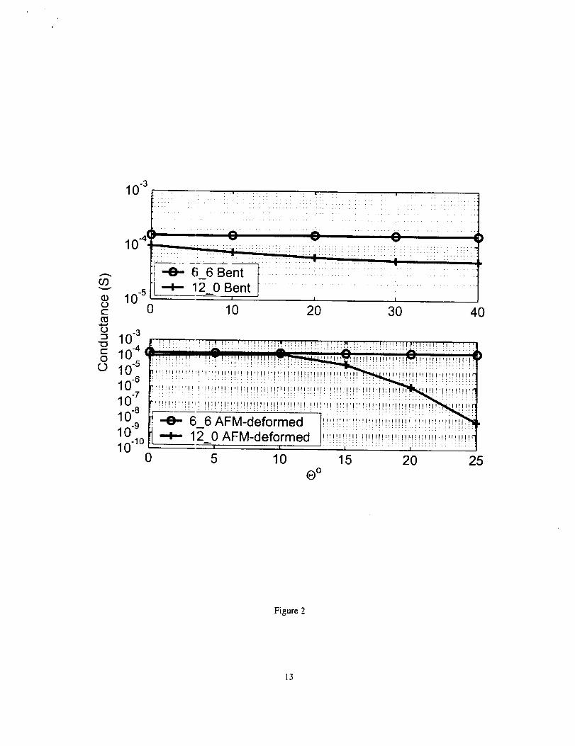
Fig. 2 displays the computed conductance (at T = 300K) for the (6, 6) and the (12, 0) tubes as a
function of bending and tip-deformation angles. The conductance remains essentially constant for the (6, 6)
tube in either bending or tip-deformation simulations. However, for the (12, 0) tube the conductance drops
by a factor of 1.9 under bending at 0=40 °, and much more significantly under tip deformation: by ~ 0.3 at
15°, two orders of magnitude at 20 °, and 4 orders of magnitude at 0=25" [For the ( 12, 0) tube, we also stud-
ied the dependence of conductance-drop as a function of tube-length. Thus at a tip-deformation angle of 15
o, tubes of 2400, 3600 anc_ ,*800 atoms have conductance-drops of 0.29, O. 13 and 0.10 respectively, which
extrapolates to - 0.08 for very long tubes.].
To analyze which part of the zigzag tube is responsible for the conductance drop, we computed
the DOS in the vicinity of the Fermi surface. Fig. 3 displays the DOS averaged over 2 unit cells [For compu-
tation of self-energies of semi-infinite carbon nanotube contacts in Eqn. (1), it was convenient to partition
the whole tube in adjacenl repeating segments, or "unit cells". For an armchair and a zigzag tube respec-
tively, the unit cell consist; of 2 and 4 rings of atoms around the circumference. This implies 24 atoms for
the (6, 6) tube and 48 atotns for the (12, 0) tube per unit cell.] (96 atoms) in three different regions of the
AFM-deformed (12, 0) tut,e for 0=25°: (1) undeformed contact, (2) highly deformed tip region, and (3) the
uniformly stretched straight regions on either side of the tip-deformed region. DOS in both tip region and6
thestraightpartshowaba_ldgapopening,whichprovesthattheconductancedropoccurse_erywhereinthe
tube.ratherthaninthetip-deformedregionalone.Thishasimportantimplicationsfortheapplicationofnan-
otubesaselectromechanicalsensors:given a metallic zigzag nanotube, one could induce a significant con-
ductance drop simply' upon uniform stretching. To check this, we computed the conductance of a uniformly
stretched ( 12, 0) tube as a fanction of strain, shown in Fig. 4, and compared it to that of AFlvl-deformed tube
from Fig. 2. Both cases sh,_w quantitatively the same drastic decay of conductance. The inset in Fig. 4 also
shows a band gap opening in transmission in the two cases [A. Heyd, A. Charlier and E. McRae, Phys. Rev.
B 55, 6820 (1997).], compared to that of a non-deformed tube.
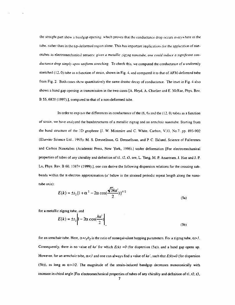
In order to explain the differences in conductance of the (6, 6) and the ( 12, O) tubes as a function
of strain, we have analyzed the bandstructures of a metallic zigzag and an armchair nanotube. Starting from
the band structure of the :'.D graphene [J. W. Mintmire and C. White, Carbon, V.33. No.7. pp. 893-902
(Elsevier Science Ltd., 1995); M. S. Dresselhaus, G. Dresselhaus, and P. C. Eklund, Science of Fullerenes
and Carbon Nanotubes (Academic Press, New York, 1996).] under deformation [For electromechanical
properties of tubes of any chirality and definition of ti, t2, t3, see, L. Yang, M. P. Anantram, J. Han and J. P.
Lu, Phys. Rev. B 60, 1387 _"(1999).], one can derive the following dispersion relations for the crossing sub-
bands within the rt-electror., approximation (a' below is the strained periodic repeat length along the nano-
tube axis):
E(k ) = +t z {1 +ct "- - 2_ cos(_3-_ ka') }l/_,z (Sa)
for a metallic zigzag tube, and
E(k) = +t, - 2ct cos
(5b)
for an armchair tube. Here, a=tF't 2 is the ratio of nonequivalent hopping parameters. For a zigzag tube, ct> 1.
Consequently, there is no value of ka' for which E(k) =0 (for dispersion (5a)), and a band gap opens up.
However, for an armchair tube, ct<i and one can always find a value ofka', such that E(k)=O (for dispersion
(5b)), as long as ct>//2, rhe magnitude of the strain-induced bandgap decreases monotonically with
increase in chiral angle [Fol electromechanical properties of tubes of any chirality and definition of t l, t2, t3,7

see.L.Yang.M.P.Anar;tram.J.HanandJ.E Lu.Phys.Rev.B60.13874(1999).].beingmaximumfora
chiralangleof0*(zigzagtandgraduallyreducingtozeroatachiralangleof30° (armchair_. An experiment
as in ref. [T. W. Tombler ,:t al., Nature 405,769 (2000).1 is, thus, expected to show a decrease in conductance
as the nanotube is deformed with an AFM tip, for all nanotubes except the armchair tube. The decrease in
conductance should be large for the metallic zigzag nanotubes, and small for nanotubes with a chiral angle
closer to armchair.
In summary, we find that both under bending and under deformation with an atomically sharp
AFM-tip, carbon nanotubes essentially remain all-hexagonal and sp2-coordinated. In the absence of sp 3
coordination, armchair tu0es remain significantly conducting even at lat'ge defoilnatiulls. However, metallic
zigzag tubes display a dramatic drop in conductance, particularly under tip-deformation. A density of states
analysis indicates that the conductance drop is distributed over the whole tube, rather than focused in the tip
region. This suggests the possibility of designing nanoelectromechanical sensors in which nanotubes are
subjected to a uniform ter_sile strain..
Acknowledgements: A.M. would like to acknowledge Accelrys Inc. for its support. A. S. and M. E A. would
like to acknowledge NASA for funding the development of the 2D Quantum Device Simulator used for the
conductance calculations Lnthis paper.
References:
1.Articlesonnanotubesn PhysicsWorld13,Issue6,pp.29-53(2000).
2.T.W.Tombleret al., Nature 405, 769 (2000).
3. M. Nardelli and J. Bemholc, Phys. Rev. B 60, R16338 (1999).
4. A. Rochefort, P. Avour_s, F. Lesage, and D. Salahub, Phys. Rev. B 60, 13824 (1999).
5. L. Liu etal., Phys. Re,,. Lett. 84, 4950 (2000).
6. A. K. Rappe etal.. J. ,am. Chem. Soc. 114, 10024 (1992).
7. N. Yao andV. Lordi, J. Appl. Phys. 84, 1939 (1998).
8. S. Iijima, C. Brabec, A Maiti, and J. Bemholc, J. Chem. Phys. 104, 2089 (1996).
9. A. Maiti, Chem. Phys. Lett. 331, 21 (2000).
10. A. Maiti, Phys. Stat. Sol. B 226, 87 (2001).
I I. A. Svizhenko, M. P. Anantram, T. R. Govindan and B. Biegel, Preprint, Submitted to JAP.
! 2. For computation of self-energies of semi-infinite carbon nanotube contacts in Eqn. (1), it was convenient
to partition the whole tube in adjacent repeating segments, or "unit cells". For an armchair and a zigzag
tube respectively, the anit cell consists of 2 and 4 rings of atoms around the circumference. This implies
24 atoms for the (6, 6) tube and 48 atoms for the (12, 0) tube per unit cell.
13. Delley, B. J. Chem. Phys. 1990, 92,508; J. Phys. Chem. 1996, I00, 6107; http://www.accelrys.com/
mstudio/dmol3.html.
14. Z. Lin and J. Harris, J Phys.: Condens. Matter 4, 1055 (1992).
15. S. H. Vosko, L. Wilk, and M. Nusair, Can. J. Phys. 58, 1200 (1980).9
16.Foratubewitha_erylargelength-to-diameterratio,thelengthL stretches to - L _ec O. 0 being the tip-
deformation angle. However. for moderately long tubes used in our simulations, the average tensile
strain in the straight pzrt of the tube is slightly lower than (sec 0 - I).
17. D. A. Papaconstantop, sulos, M. J. Mehl, S. C. Erwin and M. R. Pederson, Tight-Binding Approach to
Computational Materials Science, PE.A. Turchi, A. Gonis, and L. Colombo, eds., MRS Proceedings
491, (Materials Research Society, Warrendale, PA, 1998)
18. J.-C. Charlier, Ph. Latr_bin and T. W. Ebbesen, Phys. Rev. B 54, R8377 (1996).
19. W A. Harrison, Electr,_nic Struct,,re and the Properties of Solids (Dover, New "rot'k, 1989)
20. In the Eqs.(1-3), summation is performed over the repeating roman indices. The lower and upper indices
denote covariant and c,sntravariant components of a tensor.
21. D. Lohez and M. Lano,J, Phys. Rev. B 27, 5007 (1983).
22. For the (I 2, O) tube, wc_also studied the dependence of conductance-drop as a function of tube-length.
Thus at a tip-deformation angle of 15 o tubes of 2400, 3600 and 4800 atoms have conductance-drops of
0.29, 0.13 and 0.10 respectively, which extrapolates to ~ 0.08 for very long tubes.
23. A. Heyd, A. Charlier aTadE. McRae, Phys. Rev. B 55, 6820 (1997).
24. J. W. Mintmire and C. White, Carbon, V.33, No.7. pp. 893-902 (Elsevier Science Ltd., 1995); M. S.
Dresselhaus, G. Dress¢lhaus, and P. C. Eklund, Science of Fullerenes and Carbon Nanotubes (Aca-
demic Press, New Yorl,., 1996).
25. For electromechanical properties of tubes of any chirality and definition of t 1, t 2, t3. see, L. Yang, M. P.
Anantram, J. Hart and .f.P. Lu, Phys. Rev. B 60, 13874 (1999).
10

Fioure captions:
Fig l. DMol3-relaxed Li-til:,-deformed QM clusters for: (a) the 16.6) armchair (I 32 C-atoms); and (b) the
( 12, 0) zigzag ( 144 C-atom_). in side views. The deformation angle is 25° for both tubes. Figs. (c) and (d) are
respective views along the cube length, with the Li-tip hidden for clarity.
Fig2. Computed conductance (at T = 30OK) for the (6, 6) and ( 12, 0) nanotubes as a function of: (top) bend-
ing; and (bottom) tip-deformation. Under 40 ° bending conductance of the zigzag tube drops by a factor of
1.9, while for the armchair tube it drops by only 1.01. Under 25* tip-deformation, conductance of the zigzag
tube drops by 4 orders of magnitude, while for the armchair tube it drops only by a factor of i.05.
Fig. 3. Density of states, averaged over two unit cells (96 atoms) in three different regions of AFM-deformed
(12.0) tube at 0 = 25*. Th_- Fermi surface is at E=0. Nearly equal band gaps open up in the straight part of
the tube and in the tip regi m. Lower DOS in the tip region is due to a larger local straining of C-C bonds
close to the AF/vl-tip.
Fig. 4. Conductance of the uniformly stretched ( 12, O) tube compared to that of the tip-deformation case in
Fig. 2. Actual angles of tip-deformation are indicated. The % strain for the AFM-deformed tube is com-
puted from the average C-C bond-stretch in the middle of the straight portion of the tube [For a tube with a
very large length-to-diame!er ratio, the length L stretches to ~ L sec q, q being the tip-deformation angle.
However, for moderately k,ng tubes used in our simulations, the average tensile strain in the straight part of
the tube is slightly lower than (sec q - I).]. The inset shows transmission in the vicinity of the Fermi surface
(E = 0) for a uniform strain of 10% and a tip-deformation angle of 25", as compared to the undeformed tube.
II

_ l_'_l_ _ I
I •
I ! I
10 20 30 40
Figure 2
13

O30a
10 -4
10 "6-1.5
.
- -- contact region
tip region...... straight part
-1 -0.5 0
Energy (eV)
12_0, ® = 25 °
=
0.5 1 1.5
Figure 3
14

!5:..10_!! ': " :!!Z:::!!::!:!!!l ._ uniformly stretcl_ed I10"4 __.i_ :----,:_; ...... ' ..... ['÷" AFM-deformed
0 OE':' | : "..: ::: _ i !.:i! : !!i!:.. :f'_,!::i!::':'::
O 10-8 "_2_, i_" -*'2-[_ ............
:.:i!::1..; ' :EnerOgy!(eV): :! -- _:=8.27%, ®:25 ° :-! :!: "!
10 -10 , , , j ,
0 2 4 6 8 10
% of strain
Figure 4
15