abstract misconception #1 missing safety ground to avoid... · how to avoid common pitfalls in...
TRANSCRIPT

29th International System Safety Conference:
How to Avoid Common Pitfalls in Electrical Grounding
Garo K. Dakessian.; Raytheon Co.; Sudbury, Massachusetts, USA
Keywords: Grounding, Safety, Safety Ground, Corrosion
Abstract According to the Internet, in the US about 1000 people die from electrocution every year. As System Safety Engineers, it is our job to identify potential electrocution risks and work with design engineers to minimize the likelihood of their occurrence. The author, having spent the majority of his career as a power systems design engineer, has identified several common grounding misconceptions and in this paper exposes them and offers safer alternatives.
Misconception #1
Missing Safety Ground
The first and most obvious one has to do with the false idea that connecting electrical equipment to earth ground eliminates the risk of electrical shock. Figure 1 depicts such a case. On the left is a typical three phase Delta to Wye isolation transformer whose secondary neutral is connected to earth ground. On the right is electrical equipment which is being powered by this transformer which is also connected to earth ground, but at a different physical location. The problem with this scenario is that if a fault occurs from one of the phases to the frame of the equipment, the only path the current has to get back its source, which is the neutral of the transformer, is via earth ground. Depending on the soil conditions, the resistance of the earth between the equipment and transformer grounds may well be in the many mega ohms range. With such high resistance, the phase to neutral fault current will never reach a level sufficient to trip the circuit breaker and the entire chassis of the equipment will be energized at the potential of the phase which faulted to it. The real problem occurs when someone who is in contact with soil, or anything that is connected to earth ground also touches the faulty equipment as depicted in the figure. Because the fault current does not have a good path back to its source, it will also take a parallel path through the individual. All it takes is 10 mA or more through his chest to create a potentially lethal scenario. Cleary, the higher the voltage the higher the current, and thus, the higher the risk that the person will be electrocuted. To correct the problem one could argue that the design of the equipment will be so robust as to prevent any possible fault from phase to chassis. However, this is not realistic. The right way to correct the problem is by providing a path for the fault current to complete its circuit, which in turn will cause the breaker to trip and thus stop the equipment from becoming energized to begin with. Figure 2 shows the addition of the safety ground conductor which connects the chassis of the equipment to the neutral of the transformer. In this scenario, as soon as a fault from phase to chassis occurs in the equipment, the current seeks the easiest path back to its source, which is the safety ground conductor. In fact, this causes a short circuit from phase to neutral which causes the transformer’s circuit breaker to open in a matter of tens of milliseconds. With the breaker open, the there is zero current flowing to the faulty equipment, thus the electrocution hazard is completely eliminated.
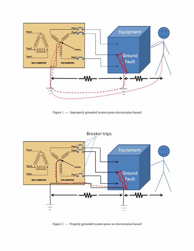
Figure 1 — Improperly grounded system poses electrocution hazard
Figure 2 — Properly grounded system poses no electrocution hazard

Misconception #2
Undersized Safety Ground Conductor
The second misconception has to do with the sizing of the safety ground conductor. It is not uncommon to find safety ground conductors which are way undersized. Unless it can handle the fault current when a phase to chassis fault occurs, this wire will most probably fuse and create the same electrocution hazard that was described in Misconception #1. To compound the problem, when this occurs there is no indication that there is anything wrong until someone actually touches the equipment and gets shocked.
To conservatively size the safety ground wire, one can simply make it no smaller than the size of the phase conductors. However, this is over-kill in higher power systems, as the safety ground is only expected to carry current until the circuit breaker trips. This typically is in the tens of milliseconds, as was mentioned earlier.
For US applications, the author found the guidance in NFPA’s (National Fire Protection Association) 70, NEC (National Electrical Code) [1] very useful. In particular, table 250-122 in Article 250 specifies the size of the safety ground conductor based on upstream overcurrent device. As can be seen in the table, up to 30A the safety ground conductor is the size at the current carrying conductors, but beyond that, it is smaller. The reason for this is most likely that the thermal time constant of copper is long enough to keep the wire from vaporizing before a typical breaker trips.
Table 1 — From Table 250.122 of the NEC.
Overcurrent Device Rating in (A)
Minimum Equipment‐Grounding
Conductor Size (AWG) 15 14 20 12 30 10 40 10 60 10 100 8 200 6
300 4
Misconception #3
Poor Grounding Caused by Paint or Corrosion
It is quite common to find equipment which although grounded, poses an electrocution hazard. Figure 3 shows such an example. Again for illustration purposes three phase power is shown coming into to pink box and also being

supplied to the blue box. Also, quite common is the termination of the safety ground near power entry point of the equipment, in this case being the pink box. In this scenario if a fault from phase C to chassis occurs in the pink box, the fault current will be able to flow back to its source as described in Misconception #1 and trip the circuit breaker. However, if paint or corrosion is present between the pink and blue boxes and the same fault from phase C to chassis occurs in the blue box, the current will not be able to flow back to the source and trip the circuit breaker. Instead, the blue box will become energizes at the potential of phase C and when someone touches it, they will be shocked provided they are making contact with earth. For this reason, it is imperative, when System Safety Engineers evaluate new equipment designs they be very diligent about making sure that:
a. such interfaces are jumpered with conductors per NEC table 250-122, or equivalent b. the mechanical interface is specifically designed, to act as a reliable long term electrical path and marked
accordingly.
Figure 3 — Effect of paint or corrosion on safety ground path
Misconception #4
Grounding – Connectorization vs. Hard Wiring
In custom designed equipment, it is quite common to have hard wired power connections which are often believed to be more reliable. From the standpoint of safety however, the author feels that connectorization is far better. This is based on the fact that in the hard wired case there is the risk of human error, while in the connectorized case, that risk does not exist. Consider the following scenario. The hard wired equipment fails and a repair person replaces it. The likelihood of him forgetting to install the safety ground to the ground stud is certainly not zero. Even worse, the equipment will function just fine without it, thus the likelihood he will notice the problem is small. As in Misconception #1, the problem occurs when a ground fault occurs from one of the phases to chassis. In the connectorized case however, the safety ground is automatically connected every time the connector is plugged in. This is one of the reasons why safety agencies such as UL have three pronged power plugs and consider the equipment safe without insisting on E1 points to be hard wired to facility ground.
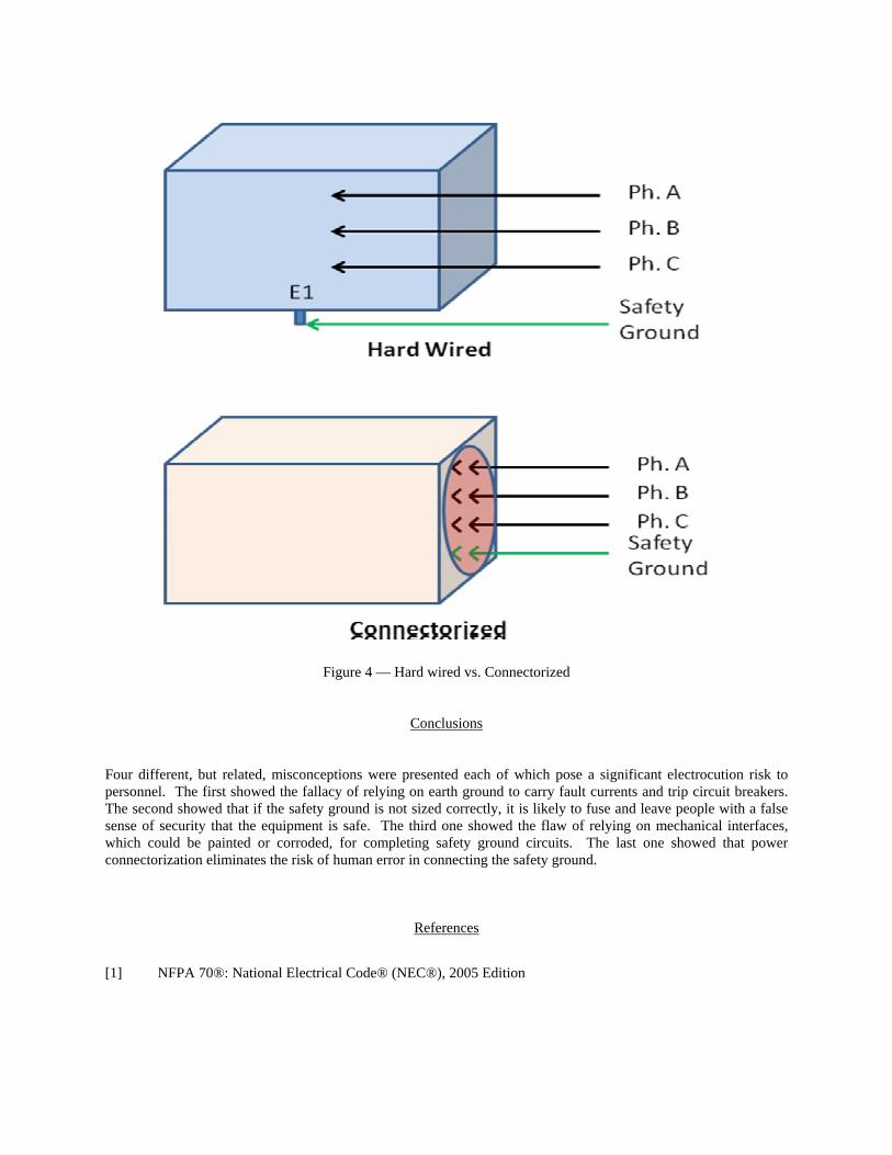
Figure 4 — Hard wired vs. Connectorized
Conclusions
Four different, but related, misconceptions were presented each of which pose a significant electrocution risk to personnel. The first showed the fallacy of relying on earth ground to carry fault currents and trip circuit breakers. The second showed that if the safety ground is not sized correctly, it is likely to fuse and leave people with a false sense of security that the equipment is safe. The third one showed the flaw of relying on mechanical interfaces, which could be painted or corroded, for completing safety ground circuits. The last one showed that power connectorization eliminates the risk of human error in connecting the safety ground.
References
[1] NFPA 70®: National Electrical Code® (NEC®), 2005 Edition

Biography Garo K. Dakessian, 528 Boston Post Rd. Sudbury MA, USA. 01776 telephone – (978) 440-4561, e-mail – [email protected]. BEEE from City College of NY and MSEE from Georgia Institute of Technology. Nine years at Bell Laboratories - designing power supplies and power systems, as well as supervising the design team. Last 23 years spent at Raytheon. Fourteen of these focused on designing power systems and managing development projects. Changed career nine years ago - exclusively focused on System Safety Engineering. Main contributions have been in minimizing personnel hazards in state-of-the-art radar systems.