about ala industries a source for yuken kogyo products and hydraulic power unit, custom manifold...
TRANSCRIPT

About ALA IndustriesA source for Yuken Kogyo products and hydraulic power unit, custom manifold assembly, and hydraulic system design
Founded in 1993 as a Manufacturer’s Representative, with a strong focus on the Latin American market.
Early work distributed two major international companies: US Tsubaki, the world’s largest manufacturer of industrial,
automotive, roller, and specialty chains Asahi Seiko, Japan’s largest manufacturer of mounted ball
bearings
A subsidiary of Industria Engineering Products Ltd., the UK’s largest distributor of power transmission products
A partner of Yuken Kogyo Co. Ltd., and the sales, marketing, service and support of Yuken products for the Americas since 1998

Who is Yuken Kogyo Co. Ltd.?
The Largest manufacturer of Industrial Hydraulics in Japan
A continual developer of hydraulic product lines, as well as machinery dependent on hydraulic power
A technology leader, Yuken was the first to develop On-Board Electronics in the early 1980’s. Yuken manufactures the fastest Servo Valve on the market.
A world leader, Yuken has relationships, offices and factories across the globe, including United Kingdom, Hong Kong, China, Taiwan, India, and the USA.
A quality leader, Yuken has been ISO 9001 since 1996 and most products conform to CE, UL, and CSA standards.

Yuken History85 year heritage, began in auto repair in 1929, grew to machine tool builder by 1931.
Introduced hydraulic honing machines in 1940, followed by development of hydraulic vane pumps and control valves. This led to today’s hydraulic equipment market.
Went public on the Tokyo Stock Exchange in 1962 as a $2,000,000 company, moved corporate headquarters to Fujisawa and sales office to Tokyo.
Established joint venture in 1969 as Taiwan Hydraulics Mfg. Co. Ltd.
Yuken employs 800 and exceeds 20,000,000,000 yen in sales.
Why Choose Yuken?Yuken’s name means Quality throughout the world.
Documented reliability of 99.96% and 100% tested. All products are designed to meet world standards.
Product IN-STOCK. Over $2,000,000 USD of Yuken product is Stocked in Valparaiso, Indiana.
ALA Industries commitment. ALA Industries commits to its customers and works with them to assure short lead times.
Full Product Offering. Yuken manufactures piston pumps, vane pumps, pressure and flow control valves, as well as solenoid operated, proportional, and servo valves.
Solution provider. Yuken and ALA Industries work hard to develop solutions for our customers. We design special products to fit the customers special needs.
Yuken Product RangeStandard offerings on ALL Yuken Products
Threaded Ports: SAE, NPT, JIS, BSPP
Sub-plate Patterns: NFPA standard with some exceptions *
Pump Flange Mountings: SAE A, B, C & D, 2 and 4 Bolt patterns **
Shafts: SAE Keyed and Spline available some require special order
Seals: Buna and Viton available
* Subplate mounted Pressure, Flow Control and Check valves use none standard/ out of date patterns. (Modular versions use NFPA patterns)
** A145 & PV2R4 pumps have a NONE standard flange. (Adapters available)

AR Series Piston PumpVariable Volume Piston PumpAluminum HousingVery Small Foot Print2300 PSI Max. / Continuous16 & 22 cc/rev High Efficiency1800 RPM MaximumPressure or Remote Compensation ControlExtremely Low Noise (65 dB at Full Flow and Pressure)Foot or Flange MountedVolume Adjustments on All Pumps

A Series Piston PumpVariable Volume Piston Pump10, 16, 22, 37, 56 & 220 cc/rev Rated At 2300 PSI Continuous70, 90, 145 cc/rev Rated At 3600 PSI Continuous98% Volumetric Efficiency90% Overall Efficiency1800 RPM Maximum11 Control optionsCLOSED LOOP PROPORTIONAL OptionLow Noise (56 cc/rev = 70 dB At Full Flow and 3000 PSI)Thru-drives AvailableFlange and Foot Mounts AvailableVolume Adjustment on All Pumps
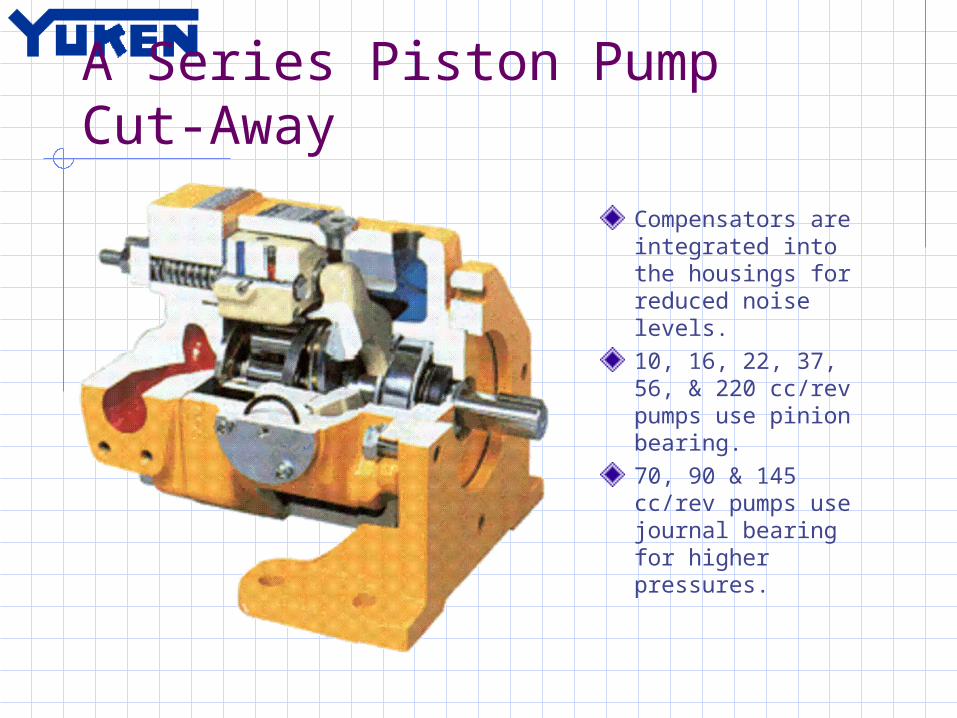
A Series Piston Pump Cut-Away
Compensators are integrated into the housings for reduced noise levels.10, 16, 22, 37, 56, & 220 cc/rev pumps use pinion bearing.70, 90 & 145 cc/rev pumps use journal bearing for higher pressures.

A Series Piston Pump Model Code
Model Code Page 7Pump RatingsPage 6Control Options Page 4, 5
Different model codeoptions for each controlType and CombinationPumps.
Models Codes located on
Pg. 29, 37, 47, 59, 68, 80
P IST ON P U M P S
3.
1 . 4 .
2 .
1
2
1
4
A
3
3
M o del N um ber D esignation / P ipe F lang e K it
S eries N u m ber
A16 3 (1 5 .8 cm /rev)
A22 3 (2 2 .2 cm /rev)
A37 3 (3 6 .9 cm /rev)
A56 3 (5 6 .2 cm /rev)
M o unting
F: F lange M tg .
L: F oo t M tg .
D irec tion o f R o ta tio n
V iew ed fro m S haf t E nd
R: C lock w ise(N o rm a l)
P res. A dj. R ange M P a (P S I)
C o ntro l T yp e
P ort P ositio n
S haf t E xtension
D esig n S td .
R e fe r to
D esig n N u m ber
32
32
32
32
K:K eyed S haf t
None:A x ia l P o rt
S:S ide P ort
01: P ressu re C o m pensator T yp e
B: C: H:
1.2 - 7 (1 70 - 102 0) 1 .2 - 1 6 (1 70 - 232 0) 1 .2 - 2 1 (1 70 - 305 0)
B: C:
1.2 - 7 (1 70 - 102 0) 1 .2 - 1 6 (1 70 - 232 0)
B: C: H:
1.2 - 7 (1 70 - 102 0) 1 .2 - 1 6 (1 70 - 232 0) 1 .2 - 2 1 (1 70 - 305 0)
-32-K-S-B-01-R-FA16
S eries N u m ber
A10 3 (1 0 .0 cm /rev)
A70 3 (7 0 .0 cm /rev)
A90 3 (9 1 .0 cm /rev)
A145 3 (1 45 cm /rev)
M o unting
F: F lange M tg .
L: F oo t M tg .
D irec tion o f R o ta tio n
V iew ed fro m S haf t E nd
R: C lock w ise(N o rm a l)
P res. A dj. R ange M P a (P S I)
C o ntro l T yp e
P ort P ositio n
D esig n S td .
R e fe r to
D esig n N u m ber
12
60
60
60
S: S ide P ort
01: P ressu re C o m pensator T yp e
B: C: H:
1.2 - 7 (1 70 - 102 0) 2 .0 - 1 6 (2 90 - 232 0) 2 .0 - 2 1 (2 90 - 305 0)
B: C: H: K:
1.2 - 7 (1 70 - 102 0) 1 .5 - 1 6 (2 20 - 232 0) 1 .8 - 2 1 (2 60 - 305 0) 2 .0 - 2 8 (2 90 - 406 0)
-60SB01R-FA70
F: F lange M tg .
M tg. Bracke t K it N u m bers
A p pro x. M ass kg ( lbs.)
L P -1 A -1 0 2.2 (4 .9 )
P um p M od el N u m bers
N am e o f P or t
Japanese S td . "JIS "
E uro pean D esig n S td .
N . A m erican D esig n S td .
Japanese S td . "JIS "
E uro pean D esig n S td .
N . A m erican D esig n S td .
E uro pean D esig n S td .
N . A m erican D esig n S td .
Japanese S td . "JIS "
T hreaded C onnec tion S ock et W elding B utt W e ld ing
P ipe F lang e K it N u m bers
S uc tio n
D ischa rge
S uc tio n
D ischa rge
S uc tio n
D ischa rge
S uc tio n
D ischa rge
F 5-06 -A -10
F 5-06 -A -10
F 5-10 -A -10
F 5-10 -A -10
F 5-12 -A -10
F 5-08 -A -10
F 5-16 -A -10
F 5-10 -A -10
F 5-06 -A -108 0
F 5-06 -A -108 0
F 5-10 -A -108 0
F 5-10 -A -108 0
F 5-12 -A -108 0
F 5-08 -A -108 0
F 5-16 -A -108 0
F 5-10 -A -108 0
F 5-06 -A -109 0
F 5-06 -A -109 0
F 5-10 -A -109 0
F 5-10 -A -109 0
F 5-12 -A -109 0
F 5-08 -A -109 0
F 5-16 -A -109 0
F 5-10 -A -109 0
F 5-06 -B -10
F 5-06 -B -10
F 5-10 -B -10
F 5-10 -B -10
F 5-12 -B -10
F 5-08 -B -10
F 5-16 -B -10
F 5-10 -B -10
F 5-06 -B -10 90
F 5-06 -B -10 90
F 5-10 -B -10 90
F 5-10 -B -10 90
F 5-12 -B -10 90
F 5-08 -B -10 90
F 5-16 -B -10 90
F 5-10 -B -10 90
F 5-06 -C -10
F 5-06 -C -10
F 5-10 -C -10
F 5-10 -C -10
F 5-12 -C -10
F 5-08 -C -10
F 5-16 -C -10
F 5-10 -C -10
F 5-06 -C -109 0
F 5-06 -C -109 0
F 5-10 -C -109 0
F 5-10 -C -109 0
F 5-12 -C -109 0
F 5-08 -C -109 0
F 5-16 -C -109 0
F 5-10 -C -109 0
A 1 6--R -01 A 2 2--R -01
A 3 7--R -01 A 5 6--R -01
A 7 0-R 01
A 9 0-R 01 A 1 45 -R 0 1
N o.7
"A" Series P iston Pumps Pressure Compensator T ype
A10 / A16 / A22 / A37 / A56 / A70 / A90 / A145
D esig n S tanda rd s: N o ne 80 90
Japanese S tand ard "JIS " E uro pean D esig n S tanda rd N . A m erican D esig n S tanda rd
. .. .. . .. . .. . .. .. . .. . .. .. . . . .. .. . .. . .. .. . .
A va ilable to sup ply pum p w ith anti-c lo ck w ise ro ta tio n. C onsult Y u ken fo r d e ta ils.
W hen A 10 pu m p is used as the fo ot M tg ., o rd er the M tg . Brack et k it show n be lo w sepa ra tely . R e fe r to p ag e 1 7 for d im ensio ns of the M tg. brack et.
T he axial po rt is not ava ilab le to the N .A m erican D esig n S tanda rd of A 3 7 and A 5 6.
N o te : T he m ounting brack et k it consists of a m ounting brack et, 2 hex . bolts and 2 p la in w ashe r.
M o d e l N u m b e r D e sig n a tio n
P ip e F la n g e K itsPipe fla n g e k its a r e a va ila ble. W h en or d erin g , sp eci fy th e k it n u m ber fr om th e ta ble be low .
In ca se of using socke t w e ld ing flanges, the re is a c ase w he re the op era ting pressu re should be se t lo w er than the norm a l because of streng th of the f langes. T he re fo re , p lease pay cau tiou s a ttention to the o pe ra ting pressu re w hen the so ck et w e ld ing flanges are used .
D e ta ils of the p ipe flange k its are g iven in the C a talog ue N o. P u b. E C -30 01

AH Series Piston Pump
Variable Volume Piston Pump3600 PSI Continuous4500 PSI Maximum16, 37 & 56 cc/revHigh Efficiency2500 RPM up to 3600 RPMPressure Compensated ControlLow Noise (56 cc/rev = 68 dB at 1800 RPM and 3000 PSI)Flange and Foot Mounts AvailableVolume Adjustment on All Pumps

New A3H Series Piston Pump
Variable Volume Piston PumpSmall foot print4000 PSI Continuous5000 PSI Maximum16, 37, 56, 70, 100, 145 & 180 cc/revHigh EfficiencyHigh Speed for Mobile Applications5 Control Types (Including Load Sense & HP Control)Good NoiseThru Drive Option AvailableVolume Adjustment on All PumpsStock Available October 2005 (145 & 180 cc/rev available first)

Piston Pump – Sales ScoopQUALITY
Market Leader in Asian Machine Tool and Heavy Industry
100% Tested before Shipping
PRODUCT RANGE 10, 16, 22, 37, 56, 70, 90, 145 & 220 cc/rev 11 Control Options CLOSED LOOP Proportional Pump – Flow and Pressure
“Includes the On Board Electronics (OBE) option”
HIGH EFFICIENCY 90% Mechanical Efficiency or better 98% Volumetric Efficiency
LOW NOISE Typically 4-8 dB lower than Competition
Continued

Piston Pump – Sales ScoopISSUES
Pressure Capabilities – Must apply correctly THRU Drive Pumps – Must order Pre-Assembled
No Load Sense Control – We can simulate this for special customers
Weak Flexibility of Design – Controls difficult to Interchange(Design based on concept of optimize efficiency and Noise)
Point of Discussion ALA STOCKS all “01” and “07” compensators The NEW A3H pump should correct all these Issues

PVL & T Series Vane Pumps
PVL1 Series PumpsLow Pressure 730 PSI Max.1.5 up to 10.6 cc/revExtremely Low Noise (50-55 dB Max.)Porting RotatesKeyed or Tanged Shafts
50T, 150T, 250F Series PumpsLow Pressure 1020 PSI Max.6.8 up to 201.0 cc/ revInterchangeable With Former Vickers Round PumpsDual Outlet and High-Low Options AvailableKeyed shafts
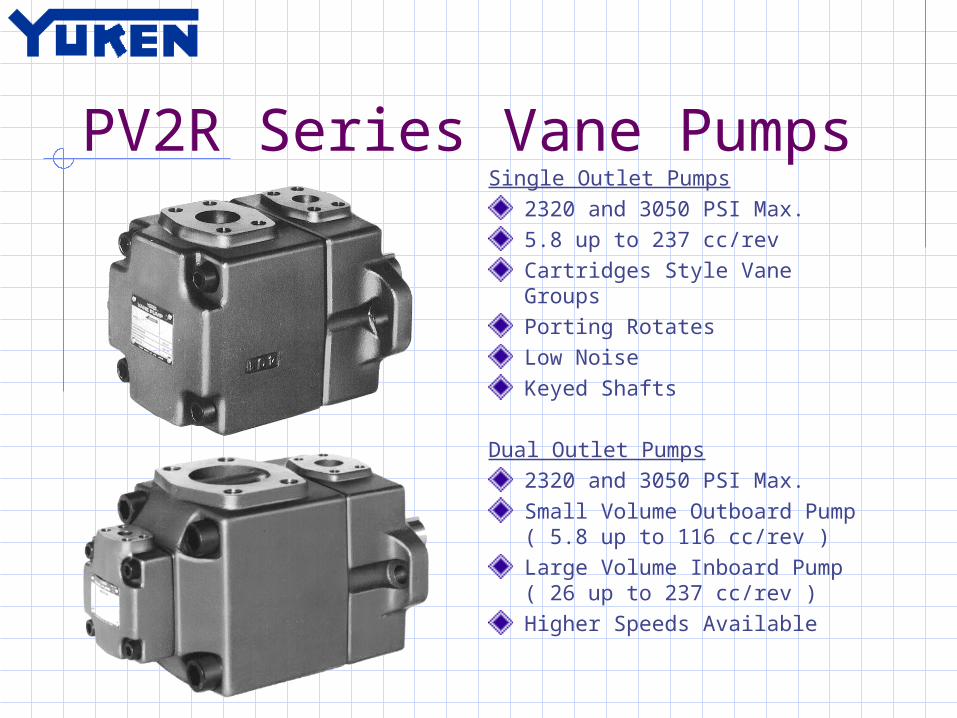
PV2R Series Vane PumpsSingle Outlet Pumps
2320 and 3050 PSI Max.5.8 up to 237 cc/revCartridges Style Vane GroupsPorting RotatesLow NoiseKeyed Shafts
Dual Outlet Pumps2320 and 3050 PSI Max.Small Volume Outboard Pump ( 5.8 up to 116 cc/rev )Large Volume Inboard Pump ( 26 up to 237 cc/rev )Higher Speeds Available
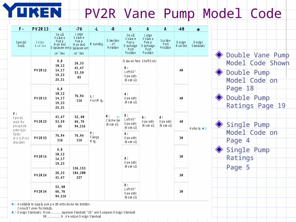
PV2R Vane Pump Model Code
Double Vane Pump Model Code ShownDouble Pump Model Code on Page 18Double Pump Ratings Page 19
Single Pump Model Code on Page 4Single Pump RatingsPage 5
V A N E P U M P S
2
1
M o del N um ber D esignation
1. 2 .
M o d e l N u m b e r D e sig n a tio n
-40
D esig n N u m ber
D esig n S tanda rd s
R efe r to
40
-L
M o unting
PV2R13 -6S m all
V o lu m e P um p
N o m inal D isplacem ent
PV2R12
S eries N u m ber
S pec ial seals for phosp ha te e ste r type flu ids (O m it if no t requ ired )
F :
F-
S pec ial S eals
D esig n S tanda rd s: N o ne 90
Japanese S tand ard "JIS " and E uropean D esig n S tanda rd N . A m erican D esig n S tanda rd
. .. .. . .. . .. . .. .. . .. . .. .. . .
3 cm /rev
L arge V o lu m e
P um p N o m inal
D isplacem ent
-76
PV2R13
PV2R23
PV2R33
6, 8 10, 12 14, 17 19, 23 25, 31
26, 33 41, 47 53, 59
65
3 cm /rev
PV2R14
PV2R24
PV2R34
-R
D irec tion of
R o ta tio n
AS m all
V o lu m e P um p
D ischa rge P or t
P ositio n
AL arge
V o lu m e P um p
D ischa rge P or t
P ositio n
A
S uc tio n P or t
P ositio n
6, 8 10, 12 14, 17 19, 23 25, 31
76, 94 116
41, 47 53, 59
52, 60 66, 76 94, 116
65
76, 94 116
76, 94 116
136, 153 184, 200
237
6, 8 10, 12 14, 17 19, 23
26, 33 41, 47
52, 60 66, 76 94, 116
F oo t M tg .L :
F lange M tg .
F :
C lock w ise (N o rm a l)
R:
(V iew ed fro m S ha ft E nd)
L eft 45 ° U p w ards (N o rm a l)
E:
U p w ards (N o rm a l)
A:
L eft 45 ° U p w ards (N o rm a l)
E:
U p w ards (N o rm a l)
A:
U p w ards (N o rm a l)
A:
L eft 45 ° U p w ards (N o rm a l)
E:
U p w ards (N o rm a l)
A:U p w ards (N o rm a l)
A:
40
40
30
30
30
30
A vailable to supp ly p um p w ith anti-clockw ise ro ta tion . C o nsu lt Y uk en for d eta ils.
G raph ic S ym bo ls
N o.18
"PV2R" SERIES
PV2R12/PV2R13/PV2R23/PV2R33/ PV2R14/PV2R24/PV2R34
Fixed D isplacement - Double
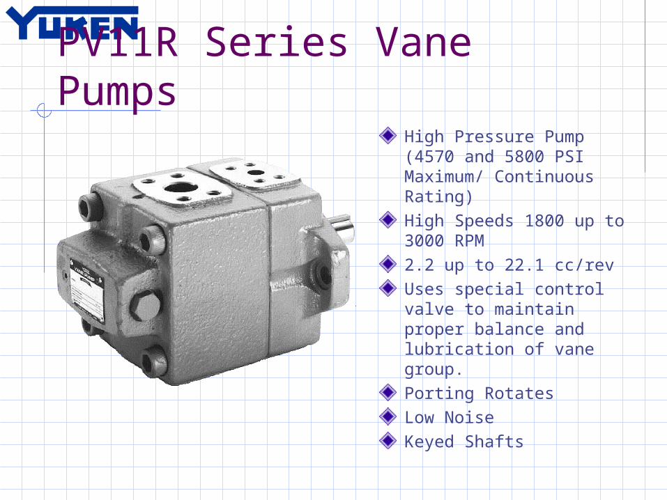
PV11R Series Vane PumpsHigh Pressure Pump (4570 and 5800 PSI Maximum/ Continuous Rating)High Speeds 1800 up to 3000 RPM2.2 up to 22.1 cc/revUses special control valve to maintain proper balance and lubrication of vane group.Porting RotatesLow NoiseKeyed Shafts

Vane Pump – Sales ScoopQUALITY
Market Leader in Asian Machine Tool and Heavy Industry
100% Tested before Shipping
PRODUCT RANGE 2 cc/rev up to 237 cc/rev Single or Double Outlet available High Pressure Model (Single Outlet Only)
HIGH EFFICIENCY Higher Efficiency than Competition
LOW NOISE Only Screw Pumps have lower noise per volume
COST EFFECTIVE Middle to Large frames are extremely competitive
Continued
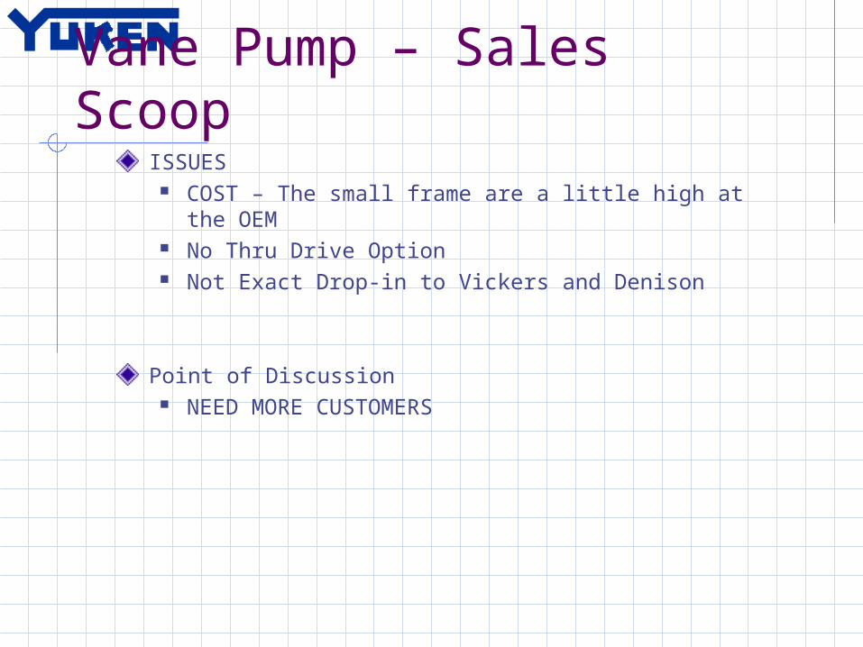
Vane Pump – Sales ScoopISSUES
COST – The small frame are a little high at the OEM No Thru Drive Option Not Exact Drop-in to Vickers and Denison
Point of Discussion NEED MORE CUSTOMERS

D/ B/ S-BG/ BS/ S-BSG Relief Valves
D Pilot Direct Acting Relief ValvesSize: 0.2 up to 4.2 GPMRating: 3000 or 3600 PSISubplate or Inline w/ Panel MountingIdeal for Remote Pilot ControlsChange Pressure by removing Collars
B/ S-BG/ BS/ S-BSG Pilot Operated Relief ValvesSize: 2.0 up to 106 GPMRating: 3630 PSI MaximumSubplate and Inline mountedOptions: Ventable, Low Noise,
Solenoid Operated (1 or 2 pressure)
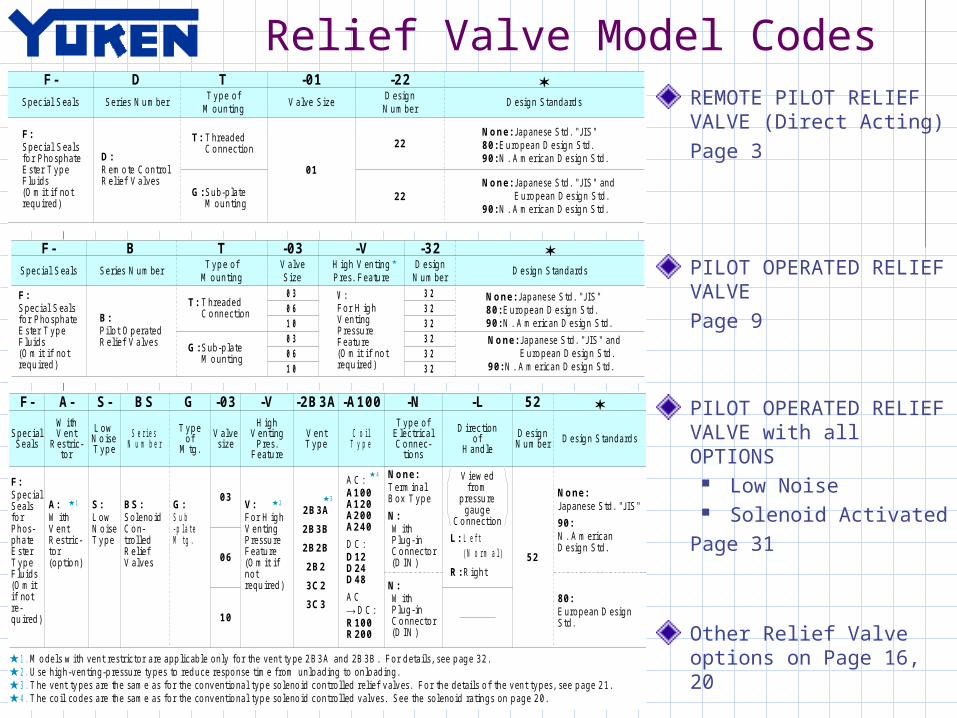
Relief Valve Model CodesREMOTE PILOT RELIEF VALVE (Direct Acting)Page 3
PILOT OPERATED RELIEF VALVEPage 9
PILOT OPERATED RELIEF VALVE with all OPTIONS
Low Noise Solenoid Activated
Page 31
Other Relief Valve options on Page 16, 20
P R ES S U R E C ON T R OL S
C
S pecifications / M o del N um ber D esignation / o thers
M o de l N u m bers
T hreaded C o nnection
S ub-p la te M o unting
M ax. O pe ra ting P res. M P a (P S I)
A p pro x. M ass kg ( lbs. )
D T ty pe D G typ e1.6 (3 .5 ) 1 .4 (3 .1 )25 (36 30)D G -01 -22D T -0 1-2 2
S eries N u m ber
F:S pec ial S ea ls fo r P ho sphate E ste r T yp e F lu ids (O m it if no t requ ired )
S pec ial S ea ls
F-
22
D
D:R em o te C ontro l R e lie f V a lves
22
01
T: T hreaded C o nnection
G: S ub-p la te M o unting
TT yp e of
M o untingV a lve S ize
D esig n N u m ber
D esig n S tanda rd s
-22 -01
None: Japanese S td . "JIS "80: E uro pean D esig n S td .90: N . A m erican D esig n S td .
None: Japanese S td . "JIS " andE uro pean D esig n S td .
90: N . A m erican D esig n S td .
V a lve M od el N u m bers
S ock et H ead C ap S c rew
A p pro x. M ass
kg ( lbs. )
Japanese S td . "JIS " and E uropean D esig n S td . N . A m erican D esig n S td .
D G -01 N o .1 0-2 4U N C 1 -3 /4 L g. 4M 5 4 5 L g .
Q ty .
V a lve M od el N u m bers
D G -01
Japanese S tand ard "JIS " E uro pean D esig n S tanda rd N . A m erican D esig n S tanda rd
S ub-p la te M o de l N u m bers
T hread S ize
S ub-p la te M o de l N u m bers
T hread S ize
S ub-p la te M o de l N u m bers
T hread S ize
D G M -0 2-2 0 R c 1 /4 D G M -0 2-2 080 1/4 B S P .F D G M -0 2-2 090 1/4 N P T 0.7 (1 .5 )
S p e c if ica tio n s
M o d e l N u m b e r D e sig n a tio n
In s tru c tio n sPr essur e is lim ited by colla r s fitte d . If a w or k in g p re ssur e ca n n ot be a t ta in ed , r em ove som e c ol la r s. O n e colla r is eq u iva le n t to 1 0 M P a (1 4 50 P SI) .If th e in te rn a l volum e of th e ve n t lin e is too la r ge , ch a tte rin g is like ly to occu r .
S u b -p la te
M oun ting b oltsA tta c h m e n t
G raphic Sym bol
S ub-p la tes a re ava ilable . S pec ify the sub-pla te m od el nu m ber from the tab le above . W hen sub-pla te s a re not used , the m ounting surface sho uld have a g oo d m achined f in ish .
N o.3
Remote C ontrol Relief Valves DT / DG -01
Threaded Connections / Sub-plate M ounting
P R ES S U R E C ON T R OL S
C
S pecifications / M o del N um ber D esignation
M o de l N u m bers
T hreaded C o nnection
S ub-p la te M o unting
M ax. O pe ra ting P ressu re
M P a (P S I)
A p pro x. M ass kg ( lbs. )
B T type B G ty pe
5.0 (1 1 .0)
P res. A dj. R ange
M P a (P S I)
M ax. F lo w L /m in
(U .S .G P M )
B T -03 --3 2 B G -0 3--32 4.7 (1 0 .4)
5 .0 (1 1 .0)
5 .6 (1 2 .3)
8 .5 (1 8 .7)
8 .7 (1 9 .2)
10 0 (2 6 .4)
20 0 (5 2 .8)
40 0 (1 06)
B T -06 --3 2 B G -0 6--32
B T -10 --3 2 B G -1 0--32
25 (36 30)N o te )
-2 5 ( -3 630 )
M o de l N u m bersM ax O p erating P res.
M P a (P S I)M ax F low
L /m in (U .S .G P M )
B F -10 --3 2
B F -16 --3 2 B F -24 --2 0
40 0 (1 06)
80 0 (2 11 ) 12 00 (317 )
25 (36 30)
21 (30 50)
S e ries N u m ber
F:S pec ial S ea ls fo r P ho sphate E ste r T yp e F lu ids (O m it if no t requ ired )
S pec ial S ea ls
F-
32 32 32 32 32 32
B
B:P ilo t O p erated R e lie f V a lves
T: T hreaded C o nnection
G: S ub-p la te M o unting
TT yp e of
M o untingV a lve S ize
H igh V enting P res. F ea tu re
D esig n S tanda rd s
-V -03
None: Japanese S td . "JIS "80: E uro pean D esig n S td .90: N . A m erican D esig n S td .
None: Japanese S td . "JIS " andE uro pean D esig n S td .
90: N . A m erican D esig n S td .
-32D esig n
N u m ber
03 06 10 03 06 10
V:F or H ig h V enting P ressu re F eatu re (O m it if no t requ ired )
S p e c if ica tio n s
N o te : R e fe r to the M inim u m ad ju stm ent P re ssure cha rac te ristic s o n page 14 .
Y u k e n c a n o ff e r f la n g e d c o n n e c t io n v a lv e s d e s c r ib e d b e lo w .F or d e ta ils , contac t u s.
U se high venting pressu re typ e to redu ce the re spo nse tim e from unload to o nload .
G raphic Sym bols
V ent C o nnec tio n
M o d e l N u m b e r D e sig n a tio n
N o.9
Pilot O perated Relief Valves BT / BG -03 / 06 /10
Threaded Connections / Sub-plate M ounting
P R ES S U R E C ON T R OL S
23
4
1
C
S pecifications / M o del N um ber D esignation
1. 2 . 3 . 4 .
F-
S pec ial S eals
F:S pec ial S eals fo r P hos- pha te E ste r T yp e F lu ids (O m it if not re - qu ired )
A-W ith V ent
R estric- tor
S-
L ow N o ise T yp e
BS
S eries N u m ber
G
T yp e of
M tg .
-03
V alve size
-VH igh
V enting P res.
F eatu re
-2B3A
V ent T yp e
-A100
C o il T yp e
-NT yp e of
E lec tr ica l C o nnec-
tio ns
-L
D irec tion of
H and le
52
D esig n N u m ber
D esig n S tanda rd s
03
06
10
A:W ith V ent R estric- tor (o ptio n)
S:L ow N o ise T yp e
BS:S oleno id C o n- tro lled R e lie f V a lves
G:S ub -p la te M tg .
V:F or H ig h V enting P ressu re F eatu re (O m it if no t requ ired )
2B3A
2B3B
2B2B
2B2
3C2
3C3
A C :A100 A120 A200 A240
D C :D12 D24 D48
A C
R100 R200
D C :
None:T erm ina l B ox T yp e
N:W ith P lug- in C o nnector (D IN )
N:W ith P lug- in C o nnector (D IN )
V iew ed from
pressu re gaug e
C o nnection
L: L eft (N o rm a l)
R: R ight52
None:Japanese S td . "JIS "
90:N . A m erican D esig n S td .
80:E uro pean D esig n S td .
M o de l N u m bers
S -B S G -03 -----5 2
S -B S G -06 -----5 2
S -B S G -10 -----5 2
S ub-p la te M o unting
M ax. O p erating P ressu re
M P a (P S I)
M ax. F lo wL /m in
(U .S .G P M )
P ressu re A d j. R ang e
M P a (P S I)
A p pro x. M ass kg ( lbs.)
D o uble S ol. S ing le S ol. W ith V ent R estrictor
25 (36 30) - 2 5
( - 36 30)
10 0 (2 6 .4)
20 0 (5 2 .8)
40 0 (1 06)
6 .3 (1 3 .9)
7 .2 (1 5 .9)
12 .7 (28 .0 )
5 .7 (1 2 .6)
6 .6 (1 4 .6)
12 .1 (26 .7 )
6 .7 (1 4 .8)
7 .6 (1 6 .8)
13 .1 (28 .9 )
N o.31
S p e c if ica tio n s
Low Noise T ype Solenoid Controlled Relief Valves Sub-plate Mounting:S-BSG -03 / 06 / 10
F or relief va lves, lo w -noise type p ilo t op e ra ted re lie f va lves a re used . F o r m inim u m ad ju stm ent pre ssures and o the r cha racte ristics, see page 18 .
Sole noid R a tin gsSolen oid ra t in g s a r e th e sa m e a s for th e con ven tion a l typ e. S ee Solen oid R a tin g s on pa g e 2 0 .
M o de ls w ith vent re str ic tor a re app licable only for the vent ty pe 2 B3 A and 2B 3B . F or d eta ils, see p ag e 32 . U se high-venting-p ressure ty pes to red uce re spo nse tim e from unlo ading to onlo ad ing . T he vent ty pes a re the sam e as for the co nventio na l typ e so leno id contro lled relie f valves. F o r the de tails o f the vent typ es, see p age 2 1 . T he co il co des a re the sam e as for the co nventio na l typ e so leno id contro lled valves. S ee the so lenoid ra tings on p age 2 0 .
M o d e l N u m b e r D e sig n a tio n

H/HC Type Pressure Control & R/RBG Reducing/ Reducing Relieving Valves
H/HC Sequence, Counter Bal., Unloading ValvesSize: 0.5 up to 66 GPMRating: 3050 PSI MaximumSetting: 2030 PSI Max. Setting AvailableSubplate and Inline MountedCounter Balances Available with 8:1 and 16:1 RatiosOptions: Bypass Check Valve, Remote ControlUnloading Valves with Check for Accumulatorand Hi-Low Circuits
R/RBG Reducing and Reducing Relieving ValvesReducing Valve Size: 0.5 up to 66 GPM Rating: 3050 PSI MaximumReducing Relieving Valve Size: 0.5 up to 33 GPMRating: 3630 PSI MaximumSubplate and Inline (R Only) mountedOptions: Bypass Check Valve, Remote Control
Pressure Controls – Sales Scoop
QUALITY Market Leader in Asian Machine Tool and Heavy Industry 100% Tested before Shipping
INLINE THREADED BODIES Very Flexible Bodies (Gauge Ports, Vent Ports, Inline
Porting for ease of mounting)
FLEXIBLE Some can easily convert into different models
LOW NOISE Low noise option
COST EFFECTIVE Very low cost in comparison to Equivalent
Continued
Pressure Controls – Sales Scoop
ISSUES Subplate style is NOT as flexible as Cartridge Valves* Space Savings – Some styles are large Subplate mounting patterns are no longer standard Counter Balances not available with 3:1 Pilot Ratio
Point of Discussion * Our Inline Threaded Body type valve can be
competitive(Relief Valves come with THRU ports – less fittings)
Our Counter Balance Valve have HIGH ratio’s 8:1 and 16:1(Excellent for Dump circuits)
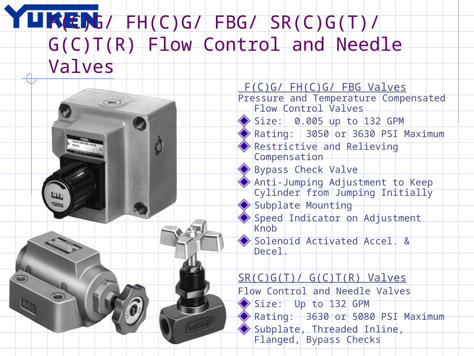
F(C)G/ FH(C)G/ FBG/ SR(C)G(T)/ G(C)T(R) Flow Control and Needle Valves
F(C)G/ FH(C)G/ FBG ValvesPressure and Temperature
Compensated Flow Control ValvesSize: 0.005 up to 132 GPMRating: 3050 or 3630 PSI MaximumRestrictive and Relieving CompensationBypass Check ValveAnti-Jumping Adjustment to Keep Cylinder from Jumping InitiallySubplate MountingSpeed Indicator on Adjustment KnobSolenoid Activated Accel. & Decel.
SR(C)G(T)/ G(C)T(R) ValvesFlow Control and Needle Valves
Size: Up to 132 GPMRating: 3630 or 5080 PSI MaximumSubplate, Threaded Inline, Flanged, Bypass Checks

ZG(T)/ ZCG(T)/ UCF1G/ UCF2G Deceleration And Feed Control Valves
ZG(T)/ ZCG(T) Deceleration ValvesSize: Up to 52.8 GPMRating: 3050 PSI MaximumCAM Operated Accel/Decel/Flow Control Bypass Check ValveSubplate, Threaded Inline MountingNormally Open or Normally ClosedNeedle Valve Option for Minimum Flow
UCF1G/ UCF2G Feed Control ValvesSize: 0.03 up to 21.1 GPMRating: 2030 PSI MaximumCAM Operated: SGL or DBL Feed ControlPressure and Temperature CompensatedSubplate MountingBypass Checks

Flow Controls – Sales ScoopQUALITY
Market Leader in Asian Machine Tool and Heavy Industry 100% Tested before Shipping
BROAD PRODUCT RANGE Excellent Flow Range 0.005 – 132 GPM Restrictive and Relieving Pressure Temperature
Compensation CAM operated – Many
BETTER CONTROL Only Proportional Closed Loop speed control gives better
accuracy and repeatability
COST EFFECTIVE Very Competitive with Equivalent Competition
Continued

Flow Controls – Sales ScoopISSUES
Subplate style is NOT as flexible as Cartridge Valves Space Savings – Some styles are large Subplate mounting patterns are no longer standard
Point of Discussion Lunge Protection on Press/Temp Compensated Valve
(Keep Cylinders from an initial lunge before compensation takes control of cylinder speed)
CAM Operation can be cost effective – Alternative to Proportional(Mobile Market uses to control Acceleration and Deceleration)

DS(H)G Directional Solenoid ValvesDS(H)G Solenoid Directional Spool Valves
NFPA Size: D03, D05, D05H, D07, D08, D10Max. Size: 291 GPMRating: 5075 PSI and 4570 PSIVoltage: 12V/24V/48V/96V DC, 110V/220V AC (Rectified available), 24V AC SpecialVoltage Range: +/- 10% and 50/60 HzConnections: DIN, NPT Conduit Box, Wire Leads, 3/5 Pin Brad HarrisWet Pin Removable Coils on ALLBolt Kits included with all valves*DIN connectors included*Conduit Box comes w/ lights & terminal strip*UL, CSA, CE Approval*OPTIONS AVAILABLE:
Slow Shift Low Watt Integrated Relay Pilot Chokes on DSHG Spool Stroke Adjuster on DSHG Covered Overrides*
* Standard for ALL similar valves

Directional Valve Model Codes
D03 Directional Valve Model Code on Page 3 (60 Series)Ratings for valve on Pages 2 and 6 (60 Series)IMPORTANT – Reference Page 10 for Reversing Coils or Changing Neutral Position (60 Series)
F- -S DSG -01 -2 B 2 A 0 -C -N -70 90 -LSpool Type
(Spools on Page 9)
D: No Spring Detent
2
A1
B
L
S: Shockless
Type
C: Spring
Centered
2, 4, 40, 60
-
B: Spring Offset
2
01
C: Spring
Centered
2, 3, 4, 40, 60, 9, 10,
11, 12 -
B: Spring Offset
2, 3, 8
Electrical connection
Design Number
Design Standard
Models with Reverse Mounting
of Solenoid
Spool Spring Arrangement
Special Two position valve (Omit if not required)
Coil Type
Manual Override
DSG: Solenoid Operated
Directional Valve
3: Three
position
2: Two
position
Special Seals
Shockless Type
Series Number
Valve Size
Number of Valve
Positions
F: Viton (Omit if
not required)
None: Standard
Type
None: Japanese Standard
AC: A100 A120 A200 A240
DC: D12 D24
D100
3: Three
position
2: Two
position
70
DC: D12 D24
D100
905: CSA
Approval
90: North
American Standard
912: 400mm
Wire Lead Option
-
L
-
R: R100 R110
P: Push
Pin with Rubber Dust Cover
None: Terminal Box Type
None: 400mm
Lead Wire Type (See
Design Standard)
R: R100 R110
N: Plug-in
Connector Type (DIN)
N12: Plug-in
Connector Type
None: Manual Override
Pin
C: Push
Button & Lock Ass'y

G-DS(H)G Shockless Directional Solenoid Valves
G-DS(H)G Shockless Solenoid Spool Valve
Directional Valve with Ramping and Creep SpeedOn Board Controller with Pot Adjustments Size: D03, D05, D07, D08Rating: 70+ GPM and 3630 PSIVoltage: 24V DC OnlyAdjustable Shift Times ON & OFF = 1 sec. Max.Adjustable Creep Speed - Zero

DM/ DHG Manual & Hydraulic Operated Directional Valves
DM Manually Operated Directional ValvesSubplate Size: D03, D05, D07, D08, D10Subplate Flow Rating: 291 GPMInline Threaded Rating: 132 GPMRating: 3050, 3630, and 4570 PSILever Operated (Lever rotates 90°, 180°,270°)2 or 3 position Spring or Detent positioningMany spool options available
Hydraulic Pilot Operated ValvesSizes: D07, D08, D10Rating: 291 GPM and 3630 PSIOptions:
Pilot Choke Valves (Slow Shift) Pilot Pistons for Fast Shift ON Spool Stroke Adjustments Pressure Centered
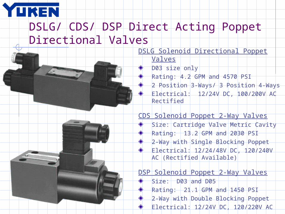
DSLG/ CDS/ DSP Direct Acting Poppet Directional Valves
DSLG Solenoid Directional Poppet ValvesD03 size onlyRating: 4.2 GPM and 4570 PSI2 Position 3-Ways/ 3 Position 4-WaysElectrical: 12/24V DC, 100/200V AC Rectified
CDS Solenoid Poppet 2-Way ValvesSize: Cartridge Valve Metric Cavity Rating: 13.2 GPM and 2030 PSI2-Way with Single Blocking PoppetElectrical: 12/24/48V DC, 120/240V AC (Rectified Available)
DSP Solenoid Poppet 2-Way ValvesSize: D03 and D05 Rating: 21.1 GPM and 1450 PSI2-Way with Double Blocking PoppetElectrical: 12/24V DC, 120/220V AC

DSLHG Pilot Operated Poppet Directional Valves - “Multi-Purpose Control Valve”
DSLHG Solenoid Directional Poppet ValvesSizes: D07, D08, D10 Rating: 132 GPM and 3630 PSI3 and 4 Position 4-Ways ConfigurationsRegenerative Circuit in position 4Voltage: 12V/24V/48V/96V DC, 110V/220V AC (Rectified available), 24V AC*Voltage Range: +/- 10% and 50/60 HzConnections: DIN, NPT Conduit Box, Wire Leads, 3/5 Pin Brad HarrisIntegral Flow Controls – Meter IN/OUTOptions: Integral Pilot Operated Check Valves Integral Non-Pilot Counter Balances

DC CAM Operated/ DR Rotary Directional Valves
DC CAM Operated Spool Directional ValvesSize: D03 and D05 up to 26.4 GPMRating: 3050 or 3630 PSI Maximum2 Position, 4-WayInline Threaded or Subplate mounting
DR Rotary Type Directional ValvesSize: 4.2 GPMRating: 1020 PSI2 or 3 Position, 4-WayDetentedInline Threaded with Flange mount
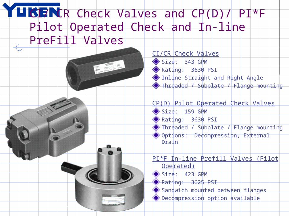
CI/ CR Check Valves and CP(D)/ PI*F Pilot Operated Check and In-line PreFill Valves
CI/CR Check ValvesSize: 343 GPMRating: 3630 PSIInline Straight and Right AngleThreaded / Subplate / Flange mounting
CP(D) Pilot Operated Check ValvesSize: 159 GPMRating: 3630 PSIThreaded / Subplate / Flange mountingOptions: Decompression, External Drain
PI*F In-line Prefill Valves (Pilot Operated)Size: 423 GPMRating: 3625 PSISandwich mounted between flangesDecompression option available

Directional Controls – Sales Scoop
QUALITY Market Leader in Asian Machine Tool and Heavy Industry 100% Tested before Shipping Rated to over 10 million Cycles CE, CSA, UL Approvals – UL testing is difficult/expensive Warranty Return = 0.04%
BROAD PRODUCT RANGE Excellent Flow Range up to 291 GPM Many Styles – NFPA Spool/Poppet styles and Specialty designs and Manual
Operated Many Options – Slow/Adjustable Shift, Low Watt, Integrated Relay, Special
Overrides Electrical Capabilities – All Voltage ranges and most connection types
BETTER PERFORMANCE Extremely repeatable performance due to machining quality
COST EFFECTIVE Extremely Competitive in ALL markets Upgrades Come Standard – Bolt Kits, Light s, DIN plugs, Terminal Strip
Continued

Directional Controls – Sales Scoop
ISSUES DSG-03 – D05 Valves and most of the older series valves
are IP64 standard – Seal upgrades available if need IP65 rating
DMG-01 – D03 Valves has a wide manual operator – Needs more space to mount
Point of Discussion Yuken’s most well rounded and competitive product ALA Industries tries to STOCK all possibilities of NFPA
solenoid valves – Only exception are the D05H and D10 size valves
Forecasts are extremely helpful with these and all our products

D03 Modular Control ValvesD03 Modular Valve
Size: 9.25 GPM and 15.9 GPM (Flow Controls)Rating: 4570 PSI MaximumVALVE TYPES (Multiple configurations of each) :
Reliefs and Reducers Integrated Pressure Switches Flow Controls (Standard and Pressure
and/or Temperature Compensated) Counter Balance (No pilot asist) Checks and PO Checks Cover Plates and Tapping Plates
“Stud” Kits available for mounting

D05 Modular Control ValvesD05 Modular Valve
Size: 18.5 GPM and 31.7 GPM (Flow Controls)Rating: 3630 PSI MaximumVALVE TYPES (Multiple configurations of each) :
Reliefs and Reducers Integrated Pressure Switches Flow Controls (Standard and Pressure
and/or Temperature Compensated) Counter Balances Checks and PO Checks Cover Plates and Tapping Plates
“Stud” Kits available for mounting

D08 and D10 Modular Control Valves
D08 and D10 Modular ValveSize: 132 GPM and 211 GPM Maximum (Respectively)Rating: 3630 PSI MaximumVALVE TYPES (Multiple configurations of each) :
Reducers Flow Controls P.O. Checks
“Stud” Kits available for mounting

Modular Valve Model CodesRefer to MASTER list at front of catalog
Choose Valve type and refer to page number for individual model code
All sizes use this same format for choosing
M ODU L A R V A L V E ST y pe of M od ular V alv e
M o de l N u m bers
Cla
ss
G rap hic S y m bo ls P age M o de l N u m bers
Cla
ss G rap hic S y m bo lsP age
S oleno id O pe ra ted D irec tional V a lve
(S -)D SG-01---60/6090 T-DSG-01---60 G-DSG-01---50/5090
T h r o t tl e a n d C h e c k V a l ve s ( fo r "A & B - L i n e s " , M e t re - i n , M e t re - o u t)
M SW -01-YX-50/5090
T h r o t tl e a n d C h e c k V a l ve s ( fo r "A & B - L i n e s " , M e t re - o u t, M e tr e - i n )
M SW -01-XY-50/5090
T h r o t tl e a n d C h e c k V a l ve s ( fo r "A & B - L i n e s " , M e t re - i n )
M SW -01-Y-50/5090
T h r o t tl e a n d C h e c k V a l ve s ( fo r "A & B - L i n e s " , M e t re - o u t)
M SW -01-X-50 /5090
T h r o t tl e a n d C h e c k V a l ve s ( fo r "B - L i n e " , M e t re - i n )
M SB-01-Y-50/5090
T h r o t tl e a n d C h e c k V a l ve s ( fo r "B - L i n e " , M e t re - o u t)
M SB-01-X -50/5090
T h r o t tl e a n d C h e c k V a l ve s ( fo r "A - L i n e " , M e t re - i n )
M SA-01-Y-50/5090
T h r o t tl e a n d C h e c k V a l ve s ( fo r "A - L i n e " , M e t re - o u t)
M SA-01-X -50/5090
C h e c k a n d T h r o tt l e V a l ve s ( fo r "P -L i n e ")
M SCP-01-30/3090
T h r o t tl e V a l ve s ( fo r "P -L i n e ")
M SP-01-50/5090
T e m p e ra t u r e C o m p e n s a t e d T h r o t tl e a n d C h e c k V a l ve s
( fo r "A & B - L i n e s " , M e t re - o u t)
M STW -01-X-10/1090
T e m p e ra t u r e C o m p e n s a t e d T h r o t tl e a n d C h e c k V a l ve s ( fo r "B - L i n e " , M e t re - o u t)
M STB-01-X -10/1090
T e m p e ra t u r e C o m p e n s a t e d T h r o t tl e a n d C h e c k V a l ve s ( fo r "A - L i n e " , M e t re - o u t)
M STA-01-X -10/1090
F lo w C o n t ro l a n d C h e c k V a l ve s ( fo r "A & B - L i n e s " , M e t re - i n )
M FW -01-Y-10/1090
F lo w C o n t ro l a n d C h e c k V a l ve s ( fo r "A & B - L i n e s " , M e t re - o u t)
M FW -01-X-10/1090
F lo w C o n t ro l a n d C h e c k V a l ve s ( fo r "B - L i n e " , M e t re - i n )
M FB-01-Y-10/1090
F lo w C o n t ro l a n d C h e c k V a l ve s ( fo r "B - L i n e " , M e t re - o u t)
M FB-01-X-10/1090
F lo w C o n t ro l a n d C h e c k V a l ve s ( fo r "A - L i n e " , M e t re - i n )
M FA-01-Y-10/1090
F lo w C o n t ro l a n d C h e c k V a l ve s ( fo r "A - L i n e " , M e t re - o u t)
M FA-01-X-10/1090
F lo w C o n t ro l V a l ve s ( fo r "P -L i n e ")
M FP-01-10/1090
P re s s u re S w i t c h e s V a l ve s ( fo r "B - L i n e " )
M JB-01-M ---10/1090
P re s s u re S w i t c h e s V a l ve s ( fo r "A - L i n e " )
M JA-01-M ---10/1090
P re s s u re S w i t c h e s V a l ve s ( fo r "P -L i n e ")
M JP-01-M ---10/1090
C o u n te rb a l a n c e V a l ve s ( fo r "A - L i n e " )
M HA-01--30/3090
S e q u e n c e V a l ve s ( fo r "P -L i n e ")
M HP-01--30/3090
B r a k e V a l ve s
M BR-01--30/3090
R e d u c i n g V a l ve s ( fo r "B - L i n e " )
M RB-01--30/3090
R e d u c i n g V a l ve s ( fo r "A - L i n e " )
M RA-01--30/3090
R e d u c i n g V a l ve s ( fo r "P -L i n e ")
M RP-01--30/3090
R e l e i f V a lv e s ( fo r "B - L i n e " )
M BB-01--30/3090
R e l e i f V a lv e s ( fo r "A - L i n e " )
M BA-01--30/3090
R e l e i f V a lv e s ( fo r "P -L i n e ")
M BP-01--30/3090
Pres
sure
Con
trol
Val
ves
Flow
Con
trol
Val
ves
7
7
7
1 0
1 0
1 0
1 3
1 5
1 5
1 8
1 8
1 8
2 2
2 2
2 2
2 2
2 2
2 2
2 2
2 6
2 6
2 6
3 0
3 2
3 4
3 4
3 4
3 4
3 4
3 4
3 4
3 4
ABTP
ABTP
01 SERIES
N o.2
T yp e o f M o d u la r V a lv e
F or the d eta ils of so leno id op e ra ted d irec tio na l va lves, see the fo llow ing cata lo gu es:(S -)D S G -01 ---60/60 90 T -D S G -01 ---60 G -D S G -01---5 0/509 0 : P u b.E C -0 40 5
P ub.E C -0 402

Modular Controls – Sales Scoop
QUALITY Market Leader in Asian Machine Tool and Heavy Industry 100% Tested before Shipping
GOOD PRODUCT RANGE D03, D05, D08 and D10 size modules Pressure/Temperature Compensated Flow Control modules - D03 &
D05 Includes Cover Plates and Tapping Plates “STUD” kits available
BETTER PERFORMANCE Extremely repeatable due to machining quality LESS Leakage
COST EFFECTIVE Extremely Competitive
Modular Controls – Sales ScoopISSUES
Limited offering of Crossover Relief Valves Limited offering of Counter Balance Valves NO - D05H and D07 modular valves
Point of Discussion STOCK of Flow Controls and P.O. Checks and some other
popular types Forecasts are extremely helpful with these and all our
products

E(H)DG Proportional Pilot Relief ValveE(H)DG Proportional Pilot Relief Valve
Size: 0.08 up to 0.53 GPMRating: 3550 PSIPerformance:
Hysteresis < 3% (< 1%*) Repeatability < 1%
Options: Separate Amplifiers
Frequency: 12 Hz 0-10V DC command 24V DC / 120V AC / 220V AC
Power
OBE (On Board Electronics) Frequency: 10 up to 27* Hz Closed Loop (OBE type only) 0-5V DC command 24V DC Power Only
*Closed Loop (Integral Transducer)
Safety Valve (Integral Relief)
Subplate Mounting Only
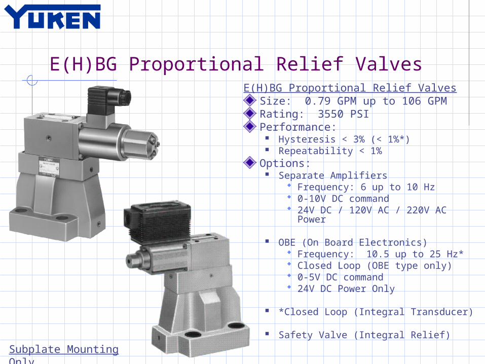
E(H)BG Proportional Relief ValvesE(H)BG Proportional Relief Valves
Size: 0.79 GPM up to 106 GPMRating: 3550 PSIPerformance:
Hysteresis < 3% (< 1%*) Repeatability < 1%
Options: Separate Amplifiers
Frequency: 6 up to 10 Hz 0-10V DC command 24V DC / 120V AC / 220V AC
Power
OBE (On Board Electronics) Frequency: 10.5 up to 25 Hz* Closed Loop (OBE type only) 0-5V DC command 24V DC Power Only
*Closed Loop (Integral Transducer)
Safety Valve (Integral Relief)
Subplate Mounting Only

E(H)RB Proportional Reducing Relieving Valves
E(H)RB Proportional Reducing Relieving ValvesSize: Up to 66 GPMRating: 3550 PSI MaximumPerformance:
Hysteresis < 3% Repeatability < 1%
Options: Separate Amplifiers
Frequency: 3-4 Hz 0-10V DC command 24V DC / 120V AC / 220V AC Power
OBE (On Board Electronics) Frequency: 3-4 Hz Integral Transducer (OBE type only) 0-5V DC command 24V DC Power Only
Open Loop with Integral Transducer
Safety Valve (Integral Relief)Subplate Mounting Only

E(H)FG Proportional Flow Control ValvesE(H)FG Proportional Flow Control Valves
Pressure Temperature Compensated Flow Control - RestrictiveRating: 3000 or 3550PSIPerformance:
Hysteresis < 3% Repeatability < 1%
Options: Separate Amplifiers
Size: 132 GPM Frequency: 4-13 Hz 0-10V DC command 24V DC / 120V AC / 220V AC
Power
OBE (On Board Electronics) Size: 66 GPM Frequency: 12 Hz 0-5V DC command 24V DC Power Only
Bypass Check Valve
Subplate Mounting Only

E(H)FBG Proportional Flow Control with Relief Valves E(H)FBG Prop. Flow Control and Relief Valves
Pressure Temperature Compensated Flow Control – Relieving “Reduces Power Consumption”Size: 0.26 up to 132 GPMRating: 3550PSIManual or Proportional Relief Valve Flow Control Performance:
Hysteresis <7% (< 3% with OBE) Repeatability < 1%
Pressure Control Performance: Hysteresis <3% (< 2% with OBE) Repeatability < 1%
Options: Separate Amplifiers
0-10V DC command per Function 24V DC / 120V AC / 220V AC Power
OBE (On Board Electronics) 0-5V DC command per Function 24V DC Power Only Optional Integrated Pressure
Transducer Separate Amplifiers
Safety Valve and External Pilot Control
Subplate Mounting Only

EDF(H)G Proportional Directional/Flow Control Valves (Open Loop and Separate Amplifier)
EDFG Proportional Directional/Flow Control ValvesSize: D03 up to 8 GPM at 500 PSI ΔPRating: 3625 PSI Power: 24V DCCommand Signal: +/-10V DCPerformance:
Frequency: 20 Hz Hysteresis < 5% Repeatability < 1%
EDFHG Proportional Directional/Flow Control ValvesSize: D05H, D07, D08Flow: 26.4 / 37.0 / 74.0 GPM at 250 PSI ΔPRating: 3550 PSI Power: 24V DCCommand Signal: +/-10V DCPerformance:
Frequency: 8-11 Hz Hysteresis < 5% Repeatability < 1%

EHDFG Proportional Directional/Flow Control Valves (On Board Electronics)
EHDFG Proportional Directional/Flow Control ValvesSize: D03, D05Rating: 7.9 and 15.9 GPM at ~300 PSI ΔPRating: 3550 PSI Power: 24V DCCommand Signal: +/-5V DCPerformance:
Frequency: 17-20 Hz Hysteresis < 5% Repeatability < 1%
EHDFG Proportional Directional/Flow Control ValvesSize: D07, D08Rating: 34 and 74 GPM at 215 PSI ΔPRating: 2275 PSI Power: 24V DCCommand Signal: +/-5V DCPerformance: (LVDT Spool Feedback)
Frequency: 45-55 Hz Hysteresis < 1% Repeatability < 1%
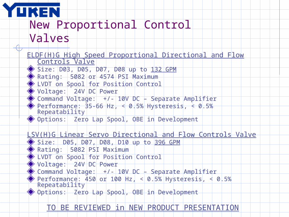
New Proportional Control Valves
ELDF(H)G High Speed Proportional Directional and Flow Controls ValveSize: D03, D05, D07, D08 up to 132 GPMRating: 5082 or 4574 PSI MaximumLVDT on Spool for Position ControlVoltage: 24V DC PowerCommand Voltage: +/- 10V DC – Separate AmplifierPerformance: 35-66 Hz, < 0.5% Hysteresis, < 0.5% RepeatabilityOptions: Zero Lap Spool, OBE in Development
LSV(H)G Linear Servo Directional and Flow Controls ValveSize: D05, D07, D08, D10 up to 396 GPMRating: 5082 PSI MaximumLVDT on Spool for Position ControlVoltage: 24V DC PowerCommand Voltage: +/- 10V DC – Separate AmplifierPerformance: 450 or 100 Hz, < 0.5% Hysteresis, < 0.5% RepeatabilityOptions: Zero Lap Spool, OBE in Development
TO BE REVIEWED in NEW PRODUCT PRESENTATION
Proportional Controls – Sales Scoop
QUALITY Market Leader in Asian Machine Tool and Heavy Industry 100% Tested before Shipping Rated for over 10 million cycles
GOOD PRODUCT RANGE Proportional/ Servo Valve option for most applications Proportional Pressure and Temperature Compensated Flow
Controls Combination Proportional Assemblies – Multiple Axis Control Most Products come with OBE option
BETTER PERFORMANCE Extremely repeatable performance due to machining quality One of the FASTEST Servo’s on the market (450 Hz/ 2 ms 0-100%)
COST EFFECTIVE Extremely Competitive in ALL markets

Proportional Controls – Sales Scoop
ISSUES No 12V DC power option No 4-20mA command signal option No Modular proportional valves Limited offering in Low End Directional/Flow controls OBE for High End Directional/Flow controls NOT available
yet OBE Valves limited to 0-5V DC or +/-5V DC command
signal Space Savings – Some styles are large Subplate mounting patterns are no longer standard All valves are only rated to IP64 Difficult to STOCK all options since line is so broad
Point of Discussion THINKING JAPANESE – The way they design a system and
why!

Compact Power UnitsYF and YP Pack Power Units
Size: 5.0 up to 16 GPMRating: 2320 PSI Continuous / 3050 PSI Intermittent (20% Duty)Power Range: 1.0 - 7.5 HP, 230V AC, 3-Phase, 50-60 HzSpecifications:
Compact Size Low Noise (as low as 53dB) Pressure Compensated, Variable Volume Adjustable Volume stop for Flow Control
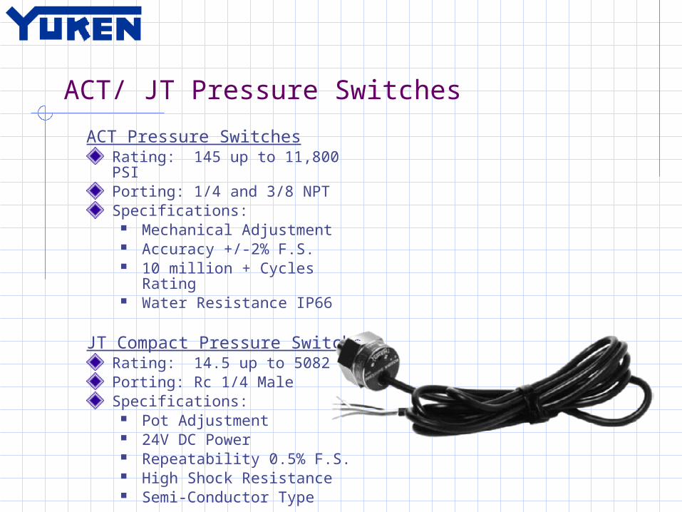
ACT/ JT Pressure Switches
ACT Pressure SwitchesRating: 145 up to 11,800 PSIPorting: 1/4 and 3/8 NPTSpecifications:
Mechanical Adjustment Accuracy +/-2% F.S. 10 million + Cycles Rating Water Resistance IP66
JT Compact Pressure SwitchesRating: 14.5 up to 5082 PSIPorting: Rc 1/4 MaleSpecifications:
Pot Adjustment 24V DC Power Repeatability 0.5% F.S. High Shock Resistance Semi-Conductor Type

Manifolds, Subplates, and FlangesManifolds, Subplates, and
FlangesMaterial: Aluminum and Ductile Rating: 3000 and 3600 PSIPorting: As RequiredSubplates available for all valve typesManifolds in D03 and D05 onlyFlanges are Code 61Stock Varies

Industry Specific O.E.M. ProductsCustom Valves, Valve Assemblies, Power Units
Product Designed Specifically for O.E.M.’s Elevator valves – Accurate Positioning and Safety Elevator Power Units – Low Noise and Efficient Injection Molding Machines – P/Q proportional
systems Drum Crusher Machines – Entire Design Servo Valve 450 Hz – Stamping Presses

MRO Only Products for the American Market
MRO Only productsHydraulic Cylinders - Sold to MRO and Japanese O.E.M.’s
All Metric Cylinder Not competitive against American O.E.M.’s Not Stocked
Logic Valves – Sold to MRO and Japanese O.E.M.’s Limited Product Range Covers and Cartridges come Pre-Assembled Not typically competitive against American
O.E.M.’s Not Currently Stocked

Why Choose Yuken?Quality Reliability Availability Commitment Full Product OfferingInnovationSolutions
Questions and Discussion?Thank you