abel-hdl reference manual - home - lattice semiconductor
TRANSCRIPT

Version 8.0
Technical Support Line: 1- 800-LATTICEDSNEXP-ABL-RM Rev 8.0.2
ABEL-HDL ReferenceManual

Copyright
This document may not, in whole or part, be copied, photocopied, reproduced,translated, or reduced to any electronic medium or machine-readable form withoutprior written consent from Lattice Semiconductor Corporation.
The software described in this manual is copyrighted and all rights are reserved byLattice Semiconductor Corporation. Information in this document is subject to changewithout notice.
The distribution and sale of this product is intended for the use of the originalpurchaser only and for use only on the computer system specified. Lawful users ofthis product are hereby licensed only to read the programs on the disks, cassettes, ortapes from their medium into the memory of a computer solely for the purpose ofexecuting them. Unauthorized copying, duplicating, selling, or otherwise distributingthis product is a violation of the law.
Trademarks
The following trademarks are recognized by Lattice Semiconductor Corporation:
Generic Array Logic, ISP, ispANALYZER, ispATE, ispCODE, ispDCD,ispDOWNLOAD, ispDS, ispDS+, ispEXPERT, ispGDS, ispGDX, ispHDL, ispJTAG,ispSmartFlow, ispStarter, ispSTREAM, ispSVF, ispTA, ispTEST, ispTURBO,ispVECTOR, ispVerilog, ispVHDL, ispVM, Latch-Lock, LHDL, pDS+, RFT, and TwinGLB are trademarks of Lattice Semiconductor Corporation.
E2CMOS, GAL, ispGAL, ispLSI, pDS, pLSI, Silicon Forest, and UltraMOS areregistered trademarks of Lattice Semiconductor Corporation.
Project Navigator is a trademark of Data I/O Corporataion. ABEL-HDL is a registeredtrademark of Data I/O Corporation.
Microsoft, Windows, and MS-DOS are registered trademarks of MicrosoftCorporation.
IBM is a registered trademark of International Business Machines Corporation.
Lattice Semiconductor Corporation5555 NE Moore Ct.Hillsboro, OR 97124
(503) 268-8000
March 2003
ABEL-HDL Reference Manual 2

Limited Warranty
Lattice Semiconductor Corporation warrants the original purchaser that the LatticeSemiconductor software shall be free from defects in material and workmanship for aperiod of ninety days from the date of purchase. If a defect covered by this limitedwarranty occurs during this 90-day warranty period, Lattice Semiconductor will repairor replace the component part at its option free of charge.
This limited warranty does not apply if the defects have been caused by negligence,accident, unreasonable or unintended use, modification, or any causes not related todefective materials or workmanship.
To receive service during the 90-day warranty period, contact Lattice SemiconductorCorporation at:
Phone: 1-800-LATTICE
E-mail: [email protected]
If the Lattice Semiconductor support personnel are unable to solve your problem overthe phone, we will provide you with instructions on returning your defective softwareto us. The cost of returning the software to the Lattice Semiconductor Service Centershall be paid by the purchaser.
Limitations on Warranty
Any applicable implied warranties, including warranties of merchantability and fitnessfor a particular purpose, are hereby limited to ninety days from the date of purchaseand are subject to the conditions set forth herein. In no event shall LatticeSemiconductor Corporation be liable for consequential or incidental damagesresulting from the breach of any expressed or implied warranties.
Purchaser’s sole remedy for any cause whatsoever, regardless of the form of action,shall be limited to the price paid to Lattice Semiconductor for the LatticeSemiconductor software.
The provisions of this limited warranty are valid in the United States only. Some statesdo not allow limitations on how long an implied warranty lasts, or exclusion ofconsequential or incidental damages, so the above limitation or exclusion may notapply to you.
This warranty provides you with specific legal rights. You may have other rights whichvary from state to state.
ABEL-HDL Reference Manual 3

Table of Contents
Preface . . . . . . . . . . . . . . . . . . . . . . . . . . . . . . . . . . . . . . . . . . . . . . . . . . . . . . . . . . . . . . . . . . . 10What is in this Manual . . . . . . . . . . . . . . . . . . . . . . . . . . . . . . . . . . . . . . . . . . . . . . . . . . . . . . . 11
Where to Look for Information . . . . . . . . . . . . . . . . . . . . . . . . . . . . . . . . . . . . . . . . . . . . . . 11Documentation Conventions . . . . . . . . . . . . . . . . . . . . . . . . . . . . . . . . . . . . . . . . . . . . . . . . . . 12Related Documentation . . . . . . . . . . . . . . . . . . . . . . . . . . . . . . . . . . . . . . . . . . . . . . . . . . . . . . 13
Chapter 1 Language Structure . . . . . . . . . . . . . . . . . . . . . . . . . . . . . . . . . . . . . . . . . . . . 14Summary . . . . . . . . . . . . . . . . . . . . . . . . . . . . . . . . . . . . . . . . . . . . . . . . . . . . . . . . . . . . . . . . . 14Introduction to ABEL-HDL . . . . . . . . . . . . . . . . . . . . . . . . . . . . . . . . . . . . . . . . . . . . . . . . . . . . 15Basic Syntax . . . . . . . . . . . . . . . . . . . . . . . . . . . . . . . . . . . . . . . . . . . . . . . . . . . . . . . . . . . . . . 15
Supported ASCII Characters . . . . . . . . . . . . . . . . . . . . . . . . . . . . . . . . . . . . . . . . . . . . . . . 16Identifiers . . . . . . . . . . . . . . . . . . . . . . . . . . . . . . . . . . . . . . . . . . . . . . . . . . . . . . . . . . . . . . 16
Reserved Identifiers (Keywords) . . . . . . . . . . . . . . . . . . . . . . . . . . . . . . . . . . . . . . . . . . 18Choosing Identifiers . . . . . . . . . . . . . . . . . . . . . . . . . . . . . . . . . . . . . . . . . . . . . . . . . . . 18
Constants . . . . . . . . . . . . . . . . . . . . . . . . . . . . . . . . . . . . . . . . . . . . . . . . . . . . . . . . . . . . . . 19Blocks . . . . . . . . . . . . . . . . . . . . . . . . . . . . . . . . . . . . . . . . . . . . . . . . . . . . . . . . . . . . . . . . . 19
Using Blocks in Logic Descriptions . . . . . . . . . . . . . . . . . . . . . . . . . . . . . . . . . . . . . . . . 20Using Blocks for State Diagram Transitions . . . . . . . . . . . . . . . . . . . . . . . . . . . . . . . . . 21
Comments . . . . . . . . . . . . . . . . . . . . . . . . . . . . . . . . . . . . . . . . . . . . . . . . . . . . . . . . . . . . . 21Numbers . . . . . . . . . . . . . . . . . . . . . . . . . . . . . . . . . . . . . . . . . . . . . . . . . . . . . . . . . . . . . . . 22Strings . . . . . . . . . . . . . . . . . . . . . . . . . . . . . . . . . . . . . . . . . . . . . . . . . . . . . . . . . . . . . . . . 24Operators, Expressions, and Equations . . . . . . . . . . . . . . . . . . . . . . . . . . . . . . . . . . . . . . . 24
Logical Operators . . . . . . . . . . . . . . . . . . . . . . . . . . . . . . . . . . . . . . . . . . . . . . . . . . . . . 25Arithmetic Operators . . . . . . . . . . . . . . . . . . . . . . . . . . . . . . . . . . . . . . . . . . . . . . . . . . . 25Relational Operators . . . . . . . . . . . . . . . . . . . . . . . . . . . . . . . . . . . . . . . . . . . . . . . . . . . 26Assignment Operators . . . . . . . . . . . . . . . . . . . . . . . . . . . . . . . . . . . . . . . . . . . . . . . . . 27Expressions. . . . . . . . . . . . . . . . . . . . . . . . . . . . . . . . . . . . . . . . . . . . . . . . . . . . . . . . . . 29Equations . . . . . . . . . . . . . . . . . . . . . . . . . . . . . . . . . . . . . . . . . . . . . . . . . . . . . . . . . . . 31Equation Blocks . . . . . . . . . . . . . . . . . . . . . . . . . . . . . . . . . . . . . . . . . . . . . . . . . . . . . . 32
Sets . . . . . . . . . . . . . . . . . . . . . . . . . . . . . . . . . . . . . . . . . . . . . . . . . . . . . . . . . . . . . . . . . . 33Set Indexing . . . . . . . . . . . . . . . . . . . . . . . . . . . . . . . . . . . . . . . . . . . . . . . . . . . . . . . . . 33Set Operations . . . . . . . . . . . . . . . . . . . . . . . . . . . . . . . . . . . . . . . . . . . . . . . . . . . . . . . 34Set Assignment and Comparison . . . . . . . . . . . . . . . . . . . . . . . . . . . . . . . . . . . . . . . . . 35Set Evaluation . . . . . . . . . . . . . . . . . . . . . . . . . . . . . . . . . . . . . . . . . . . . . . . . . . . . . . . . 37Example Equations . . . . . . . . . . . . . . . . . . . . . . . . . . . . . . . . . . . . . . . . . . . . . . . . . . . . 38Set Operation Rules . . . . . . . . . . . . . . . . . . . . . . . . . . . . . . . . . . . . . . . . . . . . . . . . . . . 38Limitations/ Restrictions on Sets . . . . . . . . . . . . . . . . . . . . . . . . . . . . . . . . . . . . . . . . . . 39
ABEL-HDL Reference Manual 4

Arguments and Argument Substitution. . . . . . . . . . . . . . . . . . . . . . . . . . . . . . . . . . . . . . . . 41Spaces in Arguments . . . . . . . . . . . . . . . . . . . . . . . . . . . . . . . . . . . . . . . . . . . . . . . . . . 42Argument Guidelines. . . . . . . . . . . . . . . . . . . . . . . . . . . . . . . . . . . . . . . . . . . . . . . . . . . 42
Basic Structure. . . . . . . . . . . . . . . . . . . . . . . . . . . . . . . . . . . . . . . . . . . . . . . . . . . . . . . . . . . . . 43Header . . . . . . . . . . . . . . . . . . . . . . . . . . . . . . . . . . . . . . . . . . . . . . . . . . . . . . . . . . . . . . . . 43Declarations . . . . . . . . . . . . . . . . . . . . . . . . . . . . . . . . . . . . . . . . . . . . . . . . . . . . . . . . . . . . 43Logic Description . . . . . . . . . . . . . . . . . . . . . . . . . . . . . . . . . . . . . . . . . . . . . . . . . . . . . . . . 45Test Vectors Section . . . . . . . . . . . . . . . . . . . . . . . . . . . . . . . . . . . . . . . . . . . . . . . . . . . . . 45End Statement . . . . . . . . . . . . . . . . . . . . . . . . . . . . . . . . . . . . . . . . . . . . . . . . . . . . . . . . . . 45Other Elements. . . . . . . . . . . . . . . . . . . . . . . . . . . . . . . . . . . . . . . . . . . . . . . . . . . . . . . . . . 45
Header . . . . . . . . . . . . . . . . . . . . . . . . . . . . . . . . . . . . . . . . . . . . . . . . . . . . . . . . . . . . . . . . . . . 46Module . . . . . . . . . . . . . . . . . . . . . . . . . . . . . . . . . . . . . . . . . . . . . . . . . . . . . . . . . . . . . . . . 46Interface . . . . . . . . . . . . . . . . . . . . . . . . . . . . . . . . . . . . . . . . . . . . . . . . . . . . . . . . . . . . . . . 46Title. . . . . . . . . . . . . . . . . . . . . . . . . . . . . . . . . . . . . . . . . . . . . . . . . . . . . . . . . . . . . . . . . . . 46
Declarations . . . . . . . . . . . . . . . . . . . . . . . . . . . . . . . . . . . . . . . . . . . . . . . . . . . . . . . . . . . . . . . 46Declarations Keyword. . . . . . . . . . . . . . . . . . . . . . . . . . . . . . . . . . . . . . . . . . . . . . . . . . . . . 47Device Declaration . . . . . . . . . . . . . . . . . . . . . . . . . . . . . . . . . . . . . . . . . . . . . . . . . . . . . . . 47Hierarchy Declarations . . . . . . . . . . . . . . . . . . . . . . . . . . . . . . . . . . . . . . . . . . . . . . . . . . . . 47
Interface Declarations . . . . . . . . . . . . . . . . . . . . . . . . . . . . . . . . . . . . . . . . . . . . . . . . . . 47Functional_block Statement . . . . . . . . . . . . . . . . . . . . . . . . . . . . . . . . . . . . . . . . . . . . . 48Example of Functional Block Instantiation . . . . . . . . . . . . . . . . . . . . . . . . . . . . . . . . . . 49
Signal Declarations. . . . . . . . . . . . . . . . . . . . . . . . . . . . . . . . . . . . . . . . . . . . . . . . . . . . . . . 50Pin Declarations . . . . . . . . . . . . . . . . . . . . . . . . . . . . . . . . . . . . . . . . . . . . . . . . . . . . . . 50Node Declarations. . . . . . . . . . . . . . . . . . . . . . . . . . . . . . . . . . . . . . . . . . . . . . . . . . . . . 50Attribute Assignment . . . . . . . . . . . . . . . . . . . . . . . . . . . . . . . . . . . . . . . . . . . . . . . . . . . 51
Constant Declarations . . . . . . . . . . . . . . . . . . . . . . . . . . . . . . . . . . . . . . . . . . . . . . . . . . . . 52Symbolic State Declarations. . . . . . . . . . . . . . . . . . . . . . . . . . . . . . . . . . . . . . . . . . . . . . . . 52
State_register Declarations. . . . . . . . . . . . . . . . . . . . . . . . . . . . . . . . . . . . . . . . . . . . . . 52State Declarations. . . . . . . . . . . . . . . . . . . . . . . . . . . . . . . . . . . . . . . . . . . . . . . . . . . . . 52
Macro Declarations. . . . . . . . . . . . . . . . . . . . . . . . . . . . . . . . . . . . . . . . . . . . . . . . . . . . . . . 53Library Declaration . . . . . . . . . . . . . . . . . . . . . . . . . . . . . . . . . . . . . . . . . . . . . . . . . . . . 53
Logic Description . . . . . . . . . . . . . . . . . . . . . . . . . . . . . . . . . . . . . . . . . . . . . . . . . . . . . . . . . . . 53Dot Extensions . . . . . . . . . . . . . . . . . . . . . . . . . . . . . . . . . . . . . . . . . . . . . . . . . . . . . . . . . . 53Equations . . . . . . . . . . . . . . . . . . . . . . . . . . . . . . . . . . . . . . . . . . . . . . . . . . . . . . . . . . . . . . 55Truth Tables . . . . . . . . . . . . . . . . . . . . . . . . . . . . . . . . . . . . . . . . . . . . . . . . . . . . . . . . . . . . 56State Descriptions . . . . . . . . . . . . . . . . . . . . . . . . . . . . . . . . . . . . . . . . . . . . . . . . . . . . . . . 56Fuse Declarations. . . . . . . . . . . . . . . . . . . . . . . . . . . . . . . . . . . . . . . . . . . . . . . . . . . . . . . . 57XOR Factors. . . . . . . . . . . . . . . . . . . . . . . . . . . . . . . . . . . . . . . . . . . . . . . . . . . . . . . . . . . . 57
Test Vectors Section . . . . . . . . . . . . . . . . . . . . . . . . . . . . . . . . . . . . . . . . . . . . . . . . . . . . . . . . 58Test Vectors . . . . . . . . . . . . . . . . . . . . . . . . . . . . . . . . . . . . . . . . . . . . . . . . . . . . . . . . . . . . 58Trace Statement . . . . . . . . . . . . . . . . . . . . . . . . . . . . . . . . . . . . . . . . . . . . . . . . . . . . . . . . . 58
End Statement . . . . . . . . . . . . . . . . . . . . . . . . . . . . . . . . . . . . . . . . . . . . . . . . . . . . . . . . . . . . . 58Other Elements . . . . . . . . . . . . . . . . . . . . . . . . . . . . . . . . . . . . . . . . . . . . . . . . . . . . . . . . . . . . 59
Directives . . . . . . . . . . . . . . . . . . . . . . . . . . . . . . . . . . . . . . . . . . . . . . . . . . . . . . . . . . . . . . 59
ABEL-HDL Reference Manual 5

Chapter 2 Design Considerations . . . . . . . . . . . . . . . . . . . . . . . . . . . . . . . . . . . . . . . . . 60Hierarchy in ABEL-HDL . . . . . . . . . . . . . . . . . . . . . . . . . . . . . . . . . . . . . . . . . . . . . . . . . . . . . . 61
Instantiating a Lower-level Module in an ABEL-HDL Source . . . . . . . . . . . . . . . . . . . . . . . 61Identifying I/O Ports in the Lower-level Module. . . . . . . . . . . . . . . . . . . . . . . . . . . . . . . 61Specifying Signal Attributes . . . . . . . . . . . . . . . . . . . . . . . . . . . . . . . . . . . . . . . . . . . . . 62Output Enables (OE). . . . . . . . . . . . . . . . . . . . . . . . . . . . . . . . . . . . . . . . . . . . . . . . . . . 62Buried Nodes . . . . . . . . . . . . . . . . . . . . . . . . . . . . . . . . . . . . . . . . . . . . . . . . . . . . . . . . 62Declaring Lower-level Modules in the Top-level Source . . . . . . . . . . . . . . . . . . . . . . . . 62Instantiating Lower-level Modules in Top-level Source. . . . . . . . . . . . . . . . . . . . . . . . . 63
Hierarchy and Retargeting and Fitting . . . . . . . . . . . . . . . . . . . . . . . . . . . . . . . . . . . . . . . . 63Redundant Nodes . . . . . . . . . . . . . . . . . . . . . . . . . . . . . . . . . . . . . . . . . . . . . . . . . . . . . 63
Merging Feedbacks . . . . . . . . . . . . . . . . . . . . . . . . . . . . . . . . . . . . . . . . . . . . . . . . . . . . . . 64Post-linked Optimization. . . . . . . . . . . . . . . . . . . . . . . . . . . . . . . . . . . . . . . . . . . . . . . . . . . 64
Node Collapsing. . . . . . . . . . . . . . . . . . . . . . . . . . . . . . . . . . . . . . . . . . . . . . . . . . . . . . . . . . . . 64Selective Collapsing . . . . . . . . . . . . . . . . . . . . . . . . . . . . . . . . . . . . . . . . . . . . . . . . . . . . . . 65
Pin-to-pin Language Features . . . . . . . . . . . . . . . . . . . . . . . . . . . . . . . . . . . . . . . . . . . . . . . . . 65Device-independence vs. Architecture-independence . . . . . . . . . . . . . . . . . . . . . . . . . . . . 65Signal Attributes . . . . . . . . . . . . . . . . . . . . . . . . . . . . . . . . . . . . . . . . . . . . . . . . . . . . . . . . . 65Signal Dot Extensions . . . . . . . . . . . . . . . . . . . . . . . . . . . . . . . . . . . . . . . . . . . . . . . . . . . . 66
Pin-to-pin vs. Detailed Descriptions for Registered Designs . . . . . . . . . . . . . . . . . . . . . . . . . . 66Using := for Pin-to-pin Descriptions . . . . . . . . . . . . . . . . . . . . . . . . . . . . . . . . . . . . . . . . . . 66
Resolving Ambiguities. . . . . . . . . . . . . . . . . . . . . . . . . . . . . . . . . . . . . . . . . . . . . . . . . . 67Detailed Circuit Descriptions . . . . . . . . . . . . . . . . . . . . . . . . . . . . . . . . . . . . . . . . . . . . . . . 67
Detailed Descriptions: Designing for Macrocells. . . . . . . . . . . . . . . . . . . . . . . . . . . . . . 68Examples of Pin-to-pin and Detailed Descriptions . . . . . . . . . . . . . . . . . . . . . . . . . . . . . . . 69
Pin-to-pin Module Description . . . . . . . . . . . . . . . . . . . . . . . . . . . . . . . . . . . . . . . . . . . . 69Detailed Module Description . . . . . . . . . . . . . . . . . . . . . . . . . . . . . . . . . . . . . . . . . . . . . 70
Detailed Module with Inverted Outputs. . . . . . . . . . . . . . . . . . . . . . . . . . . . . . . . . . . . . . . . 70When to Use Detailed Descriptions . . . . . . . . . . . . . . . . . . . . . . . . . . . . . . . . . . . . . . . . . . 72Using := for Alternative Flip-flop Types . . . . . . . . . . . . . . . . . . . . . . . . . . . . . . . . . . . . . . . 72
Using Active-low Declarations . . . . . . . . . . . . . . . . . . . . . . . . . . . . . . . . . . . . . . . . . . . . . . . . . 74Polarity Control . . . . . . . . . . . . . . . . . . . . . . . . . . . . . . . . . . . . . . . . . . . . . . . . . . . . . . . . . . . . 76
Polarity Control with Istype . . . . . . . . . . . . . . . . . . . . . . . . . . . . . . . . . . . . . . . . . . . . . . . . . 77Flip-flop Equations . . . . . . . . . . . . . . . . . . . . . . . . . . . . . . . . . . . . . . . . . . . . . . . . . . . . . . . . . . 78Feedback Considerations — Using Dot Extensions . . . . . . . . . . . . . . . . . . . . . . . . . . . . . . . . 79
Dot Extensions and Architecture-independence . . . . . . . . . . . . . . . . . . . . . . . . . . . . . . . . 80Dot Extensions and Detail Design Descriptions . . . . . . . . . . . . . . . . . . . . . . . . . . . . . . . . . 82
Using Don't Care Optimization. . . . . . . . . . . . . . . . . . . . . . . . . . . . . . . . . . . . . . . . . . . . . . . . . 84Exclusive OR Equations . . . . . . . . . . . . . . . . . . . . . . . . . . . . . . . . . . . . . . . . . . . . . . . . . . . . . 86
Optimizing XOR Devices . . . . . . . . . . . . . . . . . . . . . . . . . . . . . . . . . . . . . . . . . . . . . . . . . . 86Using XOR Operators in Equations . . . . . . . . . . . . . . . . . . . . . . . . . . . . . . . . . . . . . . . . . . 86Using Implied XORs in Equations . . . . . . . . . . . . . . . . . . . . . . . . . . . . . . . . . . . . . . . . . . . 87Using XORs for Flip-flop Emulation . . . . . . . . . . . . . . . . . . . . . . . . . . . . . . . . . . . . . . . . . . 87
ABEL-HDL Reference Manual 6

State Machines . . . . . . . . . . . . . . . . . . . . . . . . . . . . . . . . . . . . . . . . . . . . . . . . . . . . . . . . . . . . 90Use Identifiers Rather Than Numbers for States . . . . . . . . . . . . . . . . . . . . . . . . . . . . . . . . 90Powerup Register States . . . . . . . . . . . . . . . . . . . . . . . . . . . . . . . . . . . . . . . . . . . . . . . . . . 92Unsatisfied Transition Conditions . . . . . . . . . . . . . . . . . . . . . . . . . . . . . . . . . . . . . . . . . . . . 92
D-type Flip-flops . . . . . . . . . . . . . . . . . . . . . . . . . . . . . . . . . . . . . . . . . . . . . . . . . . . . . . 92Other Flip-flops . . . . . . . . . . . . . . . . . . . . . . . . . . . . . . . . . . . . . . . . . . . . . . . . . . . . . . . 93
Precautions for Using Don't Care Optimization . . . . . . . . . . . . . . . . . . . . . . . . . . . . . . . . . 94Number Adjacent States for One-bit Change. . . . . . . . . . . . . . . . . . . . . . . . . . . . . . . . . . . 98Use State Register Outputs to Identify States . . . . . . . . . . . . . . . . . . . . . . . . . . . . . . . . . . 99Using Symbolic State Descriptions. . . . . . . . . . . . . . . . . . . . . . . . . . . . . . . . . . . . . . . . . . . 99
Chapter 3 Designing with CPLDs . . . . . . . . . . . . . . . . . . . . . . . . . . . . . . . . . . . . . . . . 102CPLD Design Strategies . . . . . . . . . . . . . . . . . . . . . . . . . . . . . . . . . . . . . . . . . . . . . . . . . . . . 102
Declaring Signals . . . . . . . . . . . . . . . . . . . . . . . . . . . . . . . . . . . . . . . . . . . . . . . . . . . . . . . 102Using Intermediate Signals. . . . . . . . . . . . . . . . . . . . . . . . . . . . . . . . . . . . . . . . . . . . . . . . 103
Chapter 4 Source File Examples . . . . . . . . . . . . . . . . . . . . . . . . . . . . . . . . . . . . . . . . . 111Equations . . . . . . . . . . . . . . . . . . . . . . . . . . . . . . . . . . . . . . . . . . . . . . . . . . . . . . . . . . . . . . . . 112
Memory Address Decoder . . . . . . . . . . . . . . . . . . . . . . . . . . . . . . . . . . . . . . . . . . . . . . . . 112Design Specification . . . . . . . . . . . . . . . . . . . . . . . . . . . . . . . . . . . . . . . . . . . . . . . . . . 112Design Method . . . . . . . . . . . . . . . . . . . . . . . . . . . . . . . . . . . . . . . . . . . . . . . . . . . . . . 113Test Vectors . . . . . . . . . . . . . . . . . . . . . . . . . . . . . . . . . . . . . . . . . . . . . . . . . . . . . . . . 114
12-to-4 Multiplexer . . . . . . . . . . . . . . . . . . . . . . . . . . . . . . . . . . . . . . . . . . . . . . . . . . . . . . 114Design Specification . . . . . . . . . . . . . . . . . . . . . . . . . . . . . . . . . . . . . . . . . . . . . . . . . . 115Design Method . . . . . . . . . . . . . . . . . . . . . . . . . . . . . . . . . . . . . . . . . . . . . . . . . . . . . . 116Test Vectors . . . . . . . . . . . . . . . . . . . . . . . . . . . . . . . . . . . . . . . . . . . . . . . . . . . . . . . . 117
4-Bit Universal Counter . . . . . . . . . . . . . . . . . . . . . . . . . . . . . . . . . . . . . . . . . . . . . . . . . . 118Using Sets to Create Modes . . . . . . . . . . . . . . . . . . . . . . . . . . . . . . . . . . . . . . . . . . . . 118Counter Reset . . . . . . . . . . . . . . . . . . . . . . . . . . . . . . . . . . . . . . . . . . . . . . . . . . . . . . . 119Using Range Operators . . . . . . . . . . . . . . . . . . . . . . . . . . . . . . . . . . . . . . . . . . . . . . . 119Design Description . . . . . . . . . . . . . . . . . . . . . . . . . . . . . . . . . . . . . . . . . . . . . . . . . . . 119
Bidirectional 3-state Buffer . . . . . . . . . . . . . . . . . . . . . . . . . . . . . . . . . . . . . . . . . . . . . . . . 122Design Specification . . . . . . . . . . . . . . . . . . . . . . . . . . . . . . . . . . . . . . . . . . . . . . . . . . 122Design Method . . . . . . . . . . . . . . . . . . . . . . . . . . . . . . . . . . . . . . . . . . . . . . . . . . . . . . 123
4-Bit Comparator . . . . . . . . . . . . . . . . . . . . . . . . . . . . . . . . . . . . . . . . . . . . . . . . . . . . . . . 125Design Specification . . . . . . . . . . . . . . . . . . . . . . . . . . . . . . . . . . . . . . . . . . . . . . . . . . 125Design Method . . . . . . . . . . . . . . . . . . . . . . . . . . . . . . . . . . . . . . . . . . . . . . . . . . . . . . 125Test Vectors . . . . . . . . . . . . . . . . . . . . . . . . . . . . . . . . . . . . . . . . . . . . . . . . . . . . . . . . 127
Truth Table Examples . . . . . . . . . . . . . . . . . . . . . . . . . . . . . . . . . . . . . . . . . . . . . . . . . . . . . . 128Seven-segment Display Decoder . . . . . . . . . . . . . . . . . . . . . . . . . . . . . . . . . . . . . . . . . . . 128
Design Specification . . . . . . . . . . . . . . . . . . . . . . . . . . . . . . . . . . . . . . . . . . . . . . . . . . 128Design Method . . . . . . . . . . . . . . . . . . . . . . . . . . . . . . . . . . . . . . . . . . . . . . . . . . . . . . 128Test Vectors . . . . . . . . . . . . . . . . . . . . . . . . . . . . . . . . . . . . . . . . . . . . . . . . . . . . . . . . 130
State Diagram Examples . . . . . . . . . . . . . . . . . . . . . . . . . . . . . . . . . . . . . . . . . . . . . . . . . . . . 1313-state Sequencer . . . . . . . . . . . . . . . . . . . . . . . . . . . . . . . . . . . . . . . . . . . . . . . . . . . . . . 131
Design Specification . . . . . . . . . . . . . . . . . . . . . . . . . . . . . . . . . . . . . . . . . . . . . . . . . . 131Design Method . . . . . . . . . . . . . . . . . . . . . . . . . . . . . . . . . . . . . . . . . . . . . . . . . . . . . . 131Test Vectors . . . . . . . . . . . . . . . . . . . . . . . . . . . . . . . . . . . . . . . . . . . . . . . . . . . . . . . . 133
ABEL-HDL Reference Manual 7
Combined Logic Descriptions . . . . . . . . . . . . . . . . . . . . . . . . . . . . . . . . . . . . . . . . . . . . . . . . 134Design Specification — MUXADD . . . . . . . . . . . . . . . . . . . . . . . . . . . . . . . . . . . . . . . 136Design Method — MUXADD. . . . . . . . . . . . . . . . . . . . . . . . . . . . . . . . . . . . . . . . . . . . 136Test Vectors — MUXADD. . . . . . . . . . . . . . . . . . . . . . . . . . . . . . . . . . . . . . . . . . . . . . 137Design Specification — BINBCD . . . . . . . . . . . . . . . . . . . . . . . . . . . . . . . . . . . . . . . . 139Design Method — BINBCD. . . . . . . . . . . . . . . . . . . . . . . . . . . . . . . . . . . . . . . . . . . . . 139Test Vectors — BINBCD. . . . . . . . . . . . . . . . . . . . . . . . . . . . . . . . . . . . . . . . . . . . . . . 139Design Specification — BJACK . . . . . . . . . . . . . . . . . . . . . . . . . . . . . . . . . . . . . . . . . 142Design Method — BJACK. . . . . . . . . . . . . . . . . . . . . . . . . . . . . . . . . . . . . . . . . . . . . . 142Test Vectors — BJACK. . . . . . . . . . . . . . . . . . . . . . . . . . . . . . . . . . . . . . . . . . . . . . . . 145
Hierarchy Examples. . . . . . . . . . . . . . . . . . . . . . . . . . . . . . . . . . . . . . . . . . . . . . . . . . . . . . . . 148ABEL and ispDesignExpert Projects . . . . . . . . . . . . . . . . . . . . . . . . . . . . . . . . . . . . . . . . . . . 155
Lower-level Sources . . . . . . . . . . . . . . . . . . . . . . . . . . . . . . . . . . . . . . . . . . . . . . . . . . . . . 156
Chapter 5 Language Reference . . . . . . . . . . . . . . . . . . . . . . . . . . . . . . . . . . . . . . . . . . 157. ext — Dot Extensions . . . . . . . . . . . . . . . . . . . . . . . . . . . . . . . . . . . . . . . . . . . . . . . . . . . . . 158= — Constant Declarations . . . . . . . . . . . . . . . . . . . . . . . . . . . . . . . . . . . . . . . . . . . . . . . . . . 169'attr' — Signal Attributes. . . . . . . . . . . . . . . . . . . . . . . . . . . . . . . . . . . . . . . . . . . . . . . . . . . . . 172@Directive — Directives . . . . . . . . . . . . . . . . . . . . . . . . . . . . . . . . . . . . . . . . . . . . . . . . . . . . 173@Alternate — Alternate Operator Set . . . . . . . . . . . . . . . . . . . . . . . . . . . . . . . . . . . . . . . . . . 174@Carry — Maximum Bit-width for Arithmetic Functions . . . . . . . . . . . . . . . . . . . . . . . . . . . . 175@Const — Constant Declarations. . . . . . . . . . . . . . . . . . . . . . . . . . . . . . . . . . . . . . . . . . . . . 176@Dcset — Don't Care Set . . . . . . . . . . . . . . . . . . . . . . . . . . . . . . . . . . . . . . . . . . . . . . . . . . . 177@Dcstate — State Output Don't Cares . . . . . . . . . . . . . . . . . . . . . . . . . . . . . . . . . . . . . . . . . 178@Exit — Exit Directive. . . . . . . . . . . . . . . . . . . . . . . . . . . . . . . . . . . . . . . . . . . . . . . . . . . . . . 179@Expr — Expression Directive . . . . . . . . . . . . . . . . . . . . . . . . . . . . . . . . . . . . . . . . . . . . . . . 180@If — If Directive. . . . . . . . . . . . . . . . . . . . . . . . . . . . . . . . . . . . . . . . . . . . . . . . . . . . . . . . . . 181@Ifb — If Blank Directive. . . . . . . . . . . . . . . . . . . . . . . . . . . . . . . . . . . . . . . . . . . . . . . . . . . . 182@Ifdef — If Defined Directive . . . . . . . . . . . . . . . . . . . . . . . . . . . . . . . . . . . . . . . . . . . . . . . . 183@Ifiden — If Identical Directive . . . . . . . . . . . . . . . . . . . . . . . . . . . . . . . . . . . . . . . . . . . . . . . 184@Ifnb — If Not Blank Directive . . . . . . . . . . . . . . . . . . . . . . . . . . . . . . . . . . . . . . . . . . . . . . . 185@Ifndef — If Not Defined Directive . . . . . . . . . . . . . . . . . . . . . . . . . . . . . . . . . . . . . . . . . . . . 186@Ifniden — If Not Identical Directive. . . . . . . . . . . . . . . . . . . . . . . . . . . . . . . . . . . . . . . . . . . 187@Include — Include Directive . . . . . . . . . . . . . . . . . . . . . . . . . . . . . . . . . . . . . . . . . . . . . . . . 188@Irp — Indefinite Repeat Directive . . . . . . . . . . . . . . . . . . . . . . . . . . . . . . . . . . . . . . . . . . . . 189@Irpc — Indefinite Repeat, Character Directive . . . . . . . . . . . . . . . . . . . . . . . . . . . . . . . . . . 190@Message — Message Directive . . . . . . . . . . . . . . . . . . . . . . . . . . . . . . . . . . . . . . . . . . . . . 191@Onset — No Don't Care's . . . . . . . . . . . . . . . . . . . . . . . . . . . . . . . . . . . . . . . . . . . . . . . . . . 192@Page — Page Directive . . . . . . . . . . . . . . . . . . . . . . . . . . . . . . . . . . . . . . . . . . . . . . . . . . . 193@Radix — Default Base Numbering Directive . . . . . . . . . . . . . . . . . . . . . . . . . . . . . . . . . . . 194@Repeat — Repeat Directive . . . . . . . . . . . . . . . . . . . . . . . . . . . . . . . . . . . . . . . . . . . . . . . . 195@Setsize — Set Indexing . . . . . . . . . . . . . . . . . . . . . . . . . . . . . . . . . . . . . . . . . . . . . . . . . . . 196@Standard — Standard Operators Directive . . . . . . . . . . . . . . . . . . . . . . . . . . . . . . . . . . . . 197Async_reset and Sync_reset . . . . . . . . . . . . . . . . . . . . . . . . . . . . . . . . . . . . . . . . . . . . . . . . . 198Case. . . . . . . . . . . . . . . . . . . . . . . . . . . . . . . . . . . . . . . . . . . . . . . . . . . . . . . . . . . . . . . . . . . . 199Cycle . . . . . . . . . . . . . . . . . . . . . . . . . . . . . . . . . . . . . . . . . . . . . . . . . . . . . . . . . . . . . . . . . . . 201Constant Declarations . . . . . . . . . . . . . . . . . . . . . . . . . . . . . . . . . . . . . . . . . . . . . . . . . . . . . . 202Declarations . . . . . . . . . . . . . . . . . . . . . . . . . . . . . . . . . . . . . . . . . . . . . . . . . . . . . . . . . . . . . . 203
ABEL-HDL Reference Manual 8
Device . . . . . . . . . . . . . . . . . . . . . . . . . . . . . . . . . . . . . . . . . . . . . . . . . . . . . . . . . . . . . . . . . . 204End. . . . . . . . . . . . . . . . . . . . . . . . . . . . . . . . . . . . . . . . . . . . . . . . . . . . . . . . . . . . . . . . . . . . . 205Equations . . . . . . . . . . . . . . . . . . . . . . . . . . . . . . . . . . . . . . . . . . . . . . . . . . . . . . . . . . . . . . . . 206Functional_block . . . . . . . . . . . . . . . . . . . . . . . . . . . . . . . . . . . . . . . . . . . . . . . . . . . . . . . . . . 208Fuses . . . . . . . . . . . . . . . . . . . . . . . . . . . . . . . . . . . . . . . . . . . . . . . . . . . . . . . . . . . . . . . . . . . 211Goto . . . . . . . . . . . . . . . . . . . . . . . . . . . . . . . . . . . . . . . . . . . . . . . . . . . . . . . . . . . . . . . . . . . . 213If-Then-Else . . . . . . . . . . . . . . . . . . . . . . . . . . . . . . . . . . . . . . . . . . . . . . . . . . . . . . . . . . . . . . 214Interface (top-level) . . . . . . . . . . . . . . . . . . . . . . . . . . . . . . . . . . . . . . . . . . . . . . . . . . . . . . . . 217Interface (lower-level) . . . . . . . . . . . . . . . . . . . . . . . . . . . . . . . . . . . . . . . . . . . . . . . . . . . . . . 219Istype _ Attribute Declarations . . . . . . . . . . . . . . . . . . . . . . . . . . . . . . . . . . . . . . . . . . . . . . . . 222Library . . . . . . . . . . . . . . . . . . . . . . . . . . . . . . . . . . . . . . . . . . . . . . . . . . . . . . . . . . . . . . . . . . 227Macro . . . . . . . . . . . . . . . . . . . . . . . . . . . . . . . . . . . . . . . . . . . . . . . . . . . . . . . . . . . . . . . . . . . 228Module . . . . . . . . . . . . . . . . . . . . . . . . . . . . . . . . . . . . . . . . . . . . . . . . . . . . . . . . . . . . . . . . . . 232Node . . . . . . . . . . . . . . . . . . . . . . . . . . . . . . . . . . . . . . . . . . . . . . . . . . . . . . . . . . . . . . . . . . . 233Pin . . . . . . . . . . . . . . . . . . . . . . . . . . . . . . . . . . . . . . . . . . . . . . . . . . . . . . . . . . . . . . . . . . . . . 235Property . . . . . . . . . . . . . . . . . . . . . . . . . . . . . . . . . . . . . . . . . . . . . . . . . . . . . . . . . . . . . . . . . 237State (Declaration) . . . . . . . . . . . . . . . . . . . . . . . . . . . . . . . . . . . . . . . . . . . . . . . . . . . . . . . . . 238State (in State_diagram) . . . . . . . . . . . . . . . . . . . . . . . . . . . . . . . . . . . . . . . . . . . . . . . . . . . . 239State_diagram . . . . . . . . . . . . . . . . . . . . . . . . . . . . . . . . . . . . . . . . . . . . . . . . . . . . . . . . . . . . 240State_register. . . . . . . . . . . . . . . . . . . . . . . . . . . . . . . . . . . . . . . . . . . . . . . . . . . . . . . . . . . . . 245Sync_reset . . . . . . . . . . . . . . . . . . . . . . . . . . . . . . . . . . . . . . . . . . . . . . . . . . . . . . . . . . . . . . . 246Test_vectors . . . . . . . . . . . . . . . . . . . . . . . . . . . . . . . . . . . . . . . . . . . . . . . . . . . . . . . . . . . . . 247Title . . . . . . . . . . . . . . . . . . . . . . . . . . . . . . . . . . . . . . . . . . . . . . . . . . . . . . . . . . . . . . . . . . . . 249Trace . . . . . . . . . . . . . . . . . . . . . . . . . . . . . . . . . . . . . . . . . . . . . . . . . . . . . . . . . . . . . . . . . . . 250Truth_table. . . . . . . . . . . . . . . . . . . . . . . . . . . . . . . . . . . . . . . . . . . . . . . . . . . . . . . . . . . . . . . 251Wait . . . . . . . . . . . . . . . . . . . . . . . . . . . . . . . . . . . . . . . . . . . . . . . . . . . . . . . . . . . . . . . . . . . . 254When-Then-Else . . . . . . . . . . . . . . . . . . . . . . . . . . . . . . . . . . . . . . . . . . . . . . . . . . . . . . . . . . 255With . . . . . . . . . . . . . . . . . . . . . . . . . . . . . . . . . . . . . . . . . . . . . . . . . . . . . . . . . . . . . . . . . . . . 257XOR_factors . . . . . . . . . . . . . . . . . . . . . . . . . . . . . . . . . . . . . . . . . . . . . . . . . . . . . . . . . . . . . 258
ABEL-HDL Reference Manual 9

Preface
ABEL-HDL is a hierarchical logic description language. ABEL-HDL designdescriptions are contained in an ASCII text file in the ABEL Hardware DescriptionLanguage, ABEL-HDL. The requirements for ABEL-HDL are described in thismanual.
ABEL-HDL Reference Manual 10

What is in this Manual
What is in this ManualThis manual contains the following information:
■ Basic syntax and structure of ABEL-HDL
■ Hierarchy in ABEL-HDL
■ Node collapsing
■ Pin-to-pin language features
■ Pin-to-pin vs. detailed descriptions for registered designs
■ Equations
■ Combined logic descriptions
■ Dot extensions
■ Constant declarations
■ Signal attributes
■ Directives
■ Design keywords syntax and examples
Where to Look for Information
Chapter 1, Language Structure – Provides the basic syntax and structure of anABEL-HDL design description.
Chapter 2, Design Considerations – Discusses issues to consider when creatingan ABEL-HDL module, such as architecture-independent language features, activelow declarations, flip-flop equations, feedback considerations, and polarity control.
Chapter 3, Designing with CPLDs – Discusses issues to consider when designingfor CPLD devices.
Chapter 4, Source File Examples – Contains ABEL-HDL module examples. Theseexamples are representative of programmable logic applications and illustratesignificant ABEL features. They also help you create your own source files.
Chapter 5, Language Reference – Gives detailed information about ABEL-HDLlanguage elements.
ABEL-HDL Reference Manual 11

Documentation Conventions
Documentation ConventionsThis user manual follows the typographic conventions listed here:
Convention Definition and Usage
Italics Italicized text represents variable input. For example:
project .wdl
This means you must replace project with the file name you used for all thefiles relevant to your design.
Valuable information may be italicized for emphasis. Book titles also appear initalics.
The beginning of a procedure appears in italics. For example:
To see the waveform output of a vector simulation:
Bold Valuable information may be boldfaced for emphasis. Commands are shown inboldface. For example:
Select the Source ⇒ New menu item from the ispEXPERT SystemProject Navigator.
CourierFont
Monospaced (Courier) font indicates file and directory names and text that thesystem displays. For example:
The C:\ISPTOOLS\ISPSYS\CONFIG subdirectory contains...
BoldCourier
Bold Courier font indicates text you type in response to system prompts. Forexample:
SET YBUS [Y0..Y6];
|...| Vertical bars indicate options that are mutually exclusive; you can select only one.For example:
INPUT|OUTPUT|BIDI
“Quotes” Titles of chapters or sections in chapters in this manual are shown in quotationmarks. For example:
See Chapter 1, “Introduction.”
✍ NOTE Indicates a special note.
▲ CAUTION Indicates a situation that could cause loss of data or other problems.
❖ TIP Indicates a special hint that makes using the software easier.
⇒ Indicates a menu option leading to a submenu option. For example:
File ⇒ New
ABEL-HDL Reference Manual 12

Related Documentation
Related DocumentationIn addition to this manual, you might find the following reference material helpful:
■ Schematic Entry User Manual■ ispLSI Macro Library Reference Manual■ ispLSI 5K/8K Macro Library Supplement■ ABEL Design Manual■ ispDesignExpert User Manual■ Design Verification Tools User Manual■ ispDesignExpert Tutorial■ VHDL and Verilog Simulation User Manual
These books provide technical specifications for ispDesignExpert and ispLSI devicefamilies for Lattice Semiconductor Corp. (LSC). They give helpful information ondevice use and design development.
ABEL-HDL Reference Manual 13
Chapter 1 Language Structure
This chapter provides the basic syntax and structure of a design description inABEL-HDL. For information on specific elements, refer to Chapter 5, “LanguageReference.” You can write a source file using any editor that produces ASCII files;you are not limited to the ABEL or ispEXPERT System Text Editor.
SummaryThis chapter contains information on the following topics:
■ Introduction to ABEL-HDL and to the idea of architecture-independent andarchitecture-specific logic descriptions.
■ Basic syntax of a source file, including
• Supported ASCII characters
• Identifiers and keywords
• Constants
• Blocks
• Comments
• Numbers
• Strings
• Operators, expressions and equations
• Sets and set operation
• Arguments and argument substitution
■ Basic Structure of a design description, including
• Header
• Declarations
• Logic description
• Test vectors
• End
ABEL-HDL Reference Manual 14

Introduction to ABEL-HDL
Introduction to ABEL-HDLABEL-HDL is a hardware description language that supports a variety of behavioralinput forms, including high-level equations, state diagrams, and truth tables. TheABEL and the ABEL-HDL compiler (and supporting software) functionally verifyABEL-HDL designs through simulation. The compilers then implements the designsin PLDs or CPLDs.
You can enter designs in ABEL-HDL and verify them with little or no concern for thearchitecture of the target device.
Architecture-independent design descriptions (those that do not include devicedeclarations and pin number declarations) require more comprehensive descriptionsthan their architecture-specific counterparts. Assumptions that can be made when aparticular device is specified are not possible when no device is specified. See thesection “Device-independence vs. Architecture-independence” on page 65.
Basic SyntaxEach line in an ABEL-HDL source file must conform to the following syntax rules andrestrictions:
■ A line can be up to 150 characters long.
■ Lines are ended by a line feed (hex 0A), by a vertical tab (hex 0B), or by a formfeed (hex 0C). Carriage returns in a line are ignored, so common end-of-linesequences, such as carriage return/line feed, are interpreted as line feeds. Inmost cases, you can end a line by pressing Return.
■ Keywords, identifiers, and numbers must be separated by at least one space.Exceptions to this rule are lists of identifiers separated by commas, expressionswhere identifiers or numbers are separated by operators, or where parenthesesprovide the separation.
■ Neither spaces nor periods can be imbedded in the middle of keywords, numbers,operators, or identifiers. Spaces can appear in strings, comments, blocks, andactual arguments. For example, if the keyword MODULE is entered as MOD ULE,it is interpreted as two identifiers, MOD and ULE. Similarly, if you enter 102 05(instead of 10205), it is interpreted as two numbers, 102 and 5.
■ Keywords can be uppercase, lowercase or mixed-case.
■ Identifiers (user-supplied names and labels) can be uppercase, lowercase, ormixed-case, but they are case sensitive. The identifier, output , typed in alllowercase letters, is not the same as the identifier, Output .
ABEL-HDL Reference Manual 15

Basic Syntax
Supported ASCII CharactersAll uppercase and lowercase alphabetic characters and most other characters oncommon keyboards are supported. Valid characters are listed or shown below:
a - z (lowercase alphabet)A - Z (uppercase alphabet)0 - 9 (digits)<space><tab>! @ # $ ? + & * ( ) -
_ = + [ ] { } ; : ' "
` \ | , < > . / ^ %
IdentifiersIdentifiers are names that identify the following items:
■ devices
■ device pins or nodes
■ functional blocks
■ sets
■ input or output signals
■ constants
■ macros
■ dummy arguments
All of these items are discussed later in this chapter. The rules and restrictions foridentifiers are the same regardless of what the identifier describes.
The rules governing identifiers are listed below:
■ Identifiers can be up to 31 characters. Longer names are flagged as an error.
■ Identifiers must begin with an alphabetic character or with an underscore.
■ Other than the first character, identifiers can contain upper- and lowercasecharacters, digits, tildes (~), and underscores.
■ You cannot use spaces in an identifier. Use underscores or uppercase letters toseparate words.
■ Except for Reserved Identifiers (Keywords), identifiers are case sensitive:uppercase letters and lowercase letters are not the same.
■ You cannot use periods in an identifier, except with a supported dot extension.
ABEL-HDL Reference Manual 16

Basic Syntax
Some supported identifiers are listed below:
HELLOhello_K5inputP_hThis_is_a_long_identifierAnotherLongIdentifier
Some unsupported identifiers are listed below:
7_ Does not begin with a letter or underscore$4 Does not begin with a letter or underscoreHEL.LO Contains a period (.LO is not a valid dot extension)b6 kj Contains a space interpreted as two identifiers, b6 and kj
ABEL-HDL Reference Manual 17

Basic Syntax
Reserved Identifiers (Keywords)
The keywords listed below are reserved identifiers. Keywords cannot be used toname devices, pins, nodes, constants, sets, macros, or signals. If a keyword is usedin the wrong context, an error is flagged.
Choosing Identifiers
Choosing the right identifiers can make a source file easy to read and understand.The following suggestions can help make your logic descriptions self-explanatory,eliminating the need for extensive documentation.
■ Choose identifiers that match their function. For example, the pin you are going touse as the carry-in on an adder could be named Carry_in. For a simple OR gate,the two input pins might be given the identifiers IN1 and IN2, and the output mightbe named OR.
■ Avoid large numbers of similar identifiers. For example, do not name the outputsof a 16 bit adder: ADDER_OUTPUT_BIT_1, ADDER_OUTPUT_BIT_2, and soon.
■ Use underscores or mixed-case characters to separate words in your identifier.
THIS_IS_AN_IDENTIFIERThisIsAnIdentifier
is much easier to read thanTHISISANIDENTIFIER
async_reset fuses state
case goto state_diagram
cycle if state_register
declarations in sync_reset
device interface test_vectors
else istype then
enable (obsolete) library title
end macro trace
endcase module truth_table
endwith node wait
equations options when
external pin with
flag (obsolete) property
functional_block
ABEL-HDL Reference Manual 18

Basic Syntax
ConstantsYou can use constant values in assignment statements, truth tables, and test vectors.You can assign a constant to an identifier, and then use the identifier to specify thatvalue throughout a module (see Declarations and Module later in this chapter).Constant values can be either numeric or one of the non-numeric special constantvalues. The special constant values are listed in Table 1-1.
When you use a special constant, it must be entered as shown in Table 1-1. Withoutthe periods, .C . is an identifier named C. You can enter special constants in upper-or lowercase.
BlocksBlocks are sections of text enclosed in braces, { and }. Blocks are used in equations,state diagrams, macros, and directives. The text in a block can be on one line or it canspan many lines. Some examples of blocks are shown below:
{ this is a block }{ this is also a block, and itspans more than one line. }
{ A = B # C;D = [0, 1] + [1, 0];}
Table 1-1. Special Constants
Constant Description
.C. Clocked input (low-high-low transition)
.D. Clock down edge (high-low transition)
.F. Floating input or output signal
.K. Clocked input (high-low-high transition)
.P. Register preload
.SVn. n = 2 through 9. Drive the input to super voltage 2through 9
.U. Clock up edge (low-high transition)
.X. Don't care condition
.Z. Tri-state value
ABEL-HDL Reference Manual 19

Basic Syntax
Blocks can be nested within other blocks, as shown below, where the block { D = A }is nested within a larger block:
{ A = B $ C; { D = A; } E = C; }
Blocks and nested blocks can be useful in macros and when used with directives.(See “Macro Declarations” on page 53 and in Chapter 5, “LanguageReference.” )
If you need a brace as a character in a block, precede it with a backslash. Forexample, to specify a block containing the characters { }, write
{ \{ \} }
Using Blocks in Logic Descriptions
Using blocks can simplify the description of output logic in equations and statediagrams and allow more complex functions than possible without blocks. Blocks canimprove the readability of your design.
Blocks are supported anywhere a single equation is supported. You can use blocks insimple equations, WHEN-THEN-ELSE, IF-THEN-ELSE, CASE, and WITHstatements.
When you use equation blocks within a conditional expression (such as If-then, Case,or When-then), the logic functions are logically ANDed with the conditionalexpression.
Blocks in Equations
The following expressions, written without blocks, are limited by the inability to specifymore than one output in a When-then expression without using set notation:
Without Blocks:
WHEN (Mode == S_Data) THEN Out_data := S_in;ELSE WHEN (Mode == T_Data) THEN Out_data := T_in;WHEN (Mode == S_Data) THEN S_Valid := 1;ELSE WHEN (Mode == T_Data) THEN T_Valid := 1;
With blocks (delimited with braces), the syntax above can be simplified. The logicspecified for Out_data is logically ANDed with the WHEN clause:
With Blocks:
WHEN (Mode == S_Data) THEN { Out_data := S_in; S_Valid := 1; }ELSE WHEN (Mode == T_Data) THEN { Out_data := T_in; T_Valid := 1; }
ABEL-HDL Reference Manual 20

Basic Syntax
Blocks in State Diagrams
Blocks also provide a simpler way to write state diagram output equations. Forexample, the following two state transition statements are equivalent:
Without Blocks:
IF (Hold) THEN State1 WITH o1 := o1.fb; o2 := o2.fb; ENDWITHELSE State2;
With Blocks:
IF (Hold) THEN State1 WITH {o1 := o1.fb; o2 := o2.fb;}ELSE State2;
Using Blocks for State Diagram Transitions
Blocks can be used to nest IF-THEN and IF-THEN-ELSE statements in state diagramdescriptions, simplifying the description of complex transition logic.
Blocks for Transition Logic
Without Blocks:
IF (Hold & !Reset) THEN State1;If (Hold & Error) THEN State2;If (!Hold) THEN State3;
With Blocks:
If (Hold) THEN{ IF (!Reset) THEN State1; IF (Error) THEN State2; }ELSE State3;
CommentsComments are another way to make a source file easy to understand. Commentsexplain what is not readily apparent from the source code itself, and do not affect thecode. Comments cannot be imbedded within keywords.
You can enter comments two ways:
■ Begin with a double quotation mark (") and end with either another doublequotation mark or the end of line.
■ Begin with a double forward slash (//) and end with the end of the line. This isuseful for commenting out lines of ABEL source that contain quote-delineatedcomments.
ABEL-HDL Reference Manual 21

Basic Syntax
Examples of comments are shown in boldface below:
//gives the module a nameMODULE Basic_Logic;TITLE 'ABEL-HDL design example: simple gates'; "title
The information inside single quotation marks (apostrophes) are required strings, notcomments, and are part of the statement.
NumbersAll numeric operations in ABEL-HDL are performed to 128-bit accuracy, which meansthe supported numeric values are in the range 0 to 2128 minus 1. Numbers arerepresented in any of five forms. The four most common forms represent numbers indifferent bases. The fifth form uses alphabetic characters to represent a numericvalue.
When one of the four bases other than the default base is chosen to represent anumber, the base used is indicated by a symbol preceding the number. Table 1-2 liststhe four bases supported by ABEL-HDL and their accompanying symbols. The basesymbols can be upper- or lowercase.
When a number is specified and is not preceded by a base symbol, it is assumed tobe in the default base numbering system. The normal default base is base 10.Therefore, numbers are represented in decimal form unless they are preceded by asymbol indicating that another base is to be used.
You can change the default number base. See “@Radix — Default BaseNumbering Directive” on page 194 for more information. Examples of supportednumber specifications are shown below. The default base is base ten (decimal).
Table 1-2. Number Representation in Different Bases
Base Name Base Symbol
Binary 2 ^b
Octal 8 ^o
Decimal 10 ^d (default)
Hexadecimal 16 ^h
ABEL-HDL Reference Manual 22

Basic Syntax
You can also specify numbers by strings of one or more alphabetic characters, usingthe numeric ASCII code of the letter as the value. For example, the character “a” isdecimal 97 and hexadecimal 61 in ASCII coding. The decimal value 97 is used if “a”is specified as a number.
Specification Decimal Value
T4 = 75 75
^h75 117
^b101 5
^o17 15
^h0F 15
✍ NOTE The carat (^) is a keyboard character. It is not part of acontrol-key sequence.
ABEL-HDL Reference Manual 23

Basic Syntax
Sequences of alphabetic characters are first converted to their binary ASCII valuesand then concatenated to form numbers. Some examples are shown below:
StringsStrings are series of ASCII characters, including spaces, enclosed by apostrophes.Strings are used in the TITLE, MODULE, and OPTIONS statements, and in pin,node, and attribute declarations, as shown below:
'Hello'' Text with a space in front'' ''The preceding line is an empty string''Punctuation? is allowed!!'
You can include a single quote in a string by preceding the quote with a backslash, (\).
'It\'s easy to use ABEL'
You can include backslashes in a string by using two of them in succession.
'He\\she can use backslashes in a string'
Operators, Expressions, and EquationsItems such as constants and signal names can be brought together in expressions.Expressions combine, compare, or perform operations on the items they include toproduce a single result. The operations to be performed (addition and logical ANDare two examples) are indicated by operators within the expression.
You can use the set operator (..) in expressions and equations.
ABEL-HDL operators are divided into four basic types: logical, arithmetic, relational,and assignment. Each of these types are discussed separately, followed by adescription of how they are combined into expressions. Following the descriptions isa summary of all the operators and the rules governing them and an explanation ofhow equations use expressions.
Specification Hex Value Decimal Value
a ^h61 97
b ^h62 98
abc ^h616263 6382203
✍ NOTE The grave accent (`) is also accepted as a string delimiter andcan be used interchangeably with the apostrophe (').
ABEL-HDL Reference Manual 24

Basic Syntax
Logical Operators
Logical operators are used in expressions. ABEL-HDL incorporates the standardlogical operators listed in Table 1-3. Logical operations are performed bit by bit. Foralternate operators, refer to the “@Alternate — Alternate Operator Set” onpage 174.
Arithmetic Operators
Arithmetic operators define arithmetic relationships between items in an expression.The shift operators are included in this class because each left shift of one bit isequivalent to multiplication by 2 and a right shift of one bit is the same as divisionby 2. Table 1-4 lists the arithmetic operators.
Table 1-3. Logical Operators
Operator Description
! NOT: ones complement
& AND
# OR
$ XOR: exclusive OR
!$ XNOR: exclusive NOR
Table 1-4. Arithmetic Operators
Operator Examples Description
- -A twos complement (negation)
- A-B subtraction
+ A+B addition
Not Supported for Sets:
* A*B multiplication
/ A/B unsigned integer division
% A%B modulus: remainder from /
<< A<<B shift A left by B bits
>> A>>B shift A right by B bits
ABEL-HDL Reference Manual 25

Basic Syntax
Division is unsigned integer division: the result of division is a positive integer. Usethe modulus operator (%) to get the remainder of a division. The shift operatorsperform logical unsigned shifts. Zeros are shifted in from the left during right shiftsand in from the right during left shifts.
Relational Operators
Relational operators compare two items in an expression. Expressions formed withrelational operators produce a Boolean true or false value. Table 1-5 lists therelational operators.
All relational operations are unsigned. For example, the expression !0 > 4 is truesince the complement of !0 is 1111 (assuming 4 bits of data), which is 15 in unsignedbinary, and 15 is greater than 4. In this example, a four-bit representation wasassumed; in actual use, !0, the complement of 0, is 128 bits all set to 1.
✍ NOTE A minus sign has a different significance, depending on itsusage. When used with one operand, it indicates that the twoscomplement of the operand is to be formed. When the minussign is found between two operands, the twos complements ofthe second operand are added to the first.
Table 1-5. Relational Operators
Operators Description
== equal
!= not equal
< less than
<= less than or equal
> greater than
>= greater than or equal
ABEL-HDL Reference Manual 26
Basic Syntax
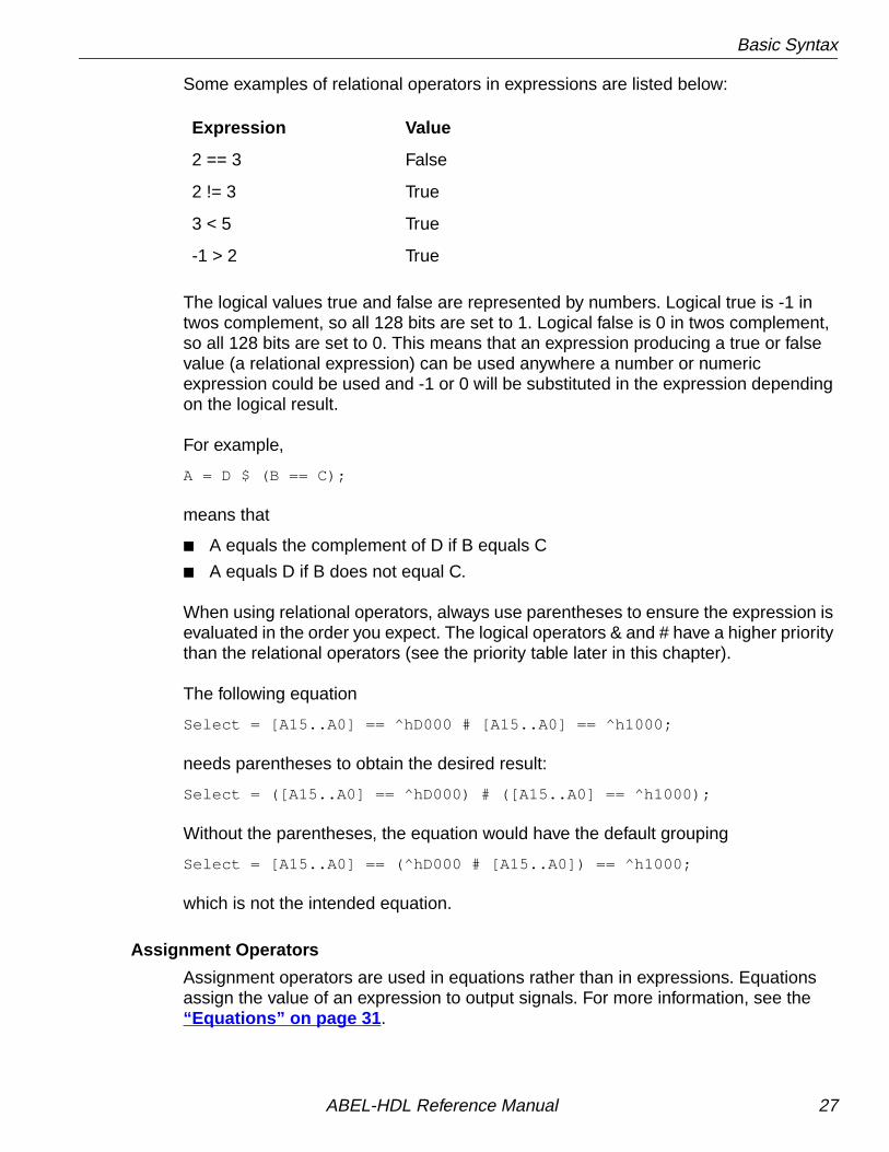
Some examples of relational operators in expressions are listed below:
The logical values true and false are represented by numbers. Logical true is -1 intwos complement, so all 128 bits are set to 1. Logical false is 0 in twos complement,so all 128 bits are set to 0. This means that an expression producing a true or falsevalue (a relational expression) can be used anywhere a number or numericexpression could be used and -1 or 0 will be substituted in the expression dependingon the logical result.
For example,
A = D $ (B == C);
means that
■ A equals the complement of D if B equals C
■ A equals D if B does not equal C.
When using relational operators, always use parentheses to ensure the expression isevaluated in the order you expect. The logical operators & and # have a higher prioritythan the relational operators (see the priority table later in this chapter).
The following equation
Select = [A15..A0] == ^hD000 # [A15..A0] == ^h1000;
needs parentheses to obtain the desired result:
Select = ([A15..A0] == ^hD000) # ([A15..A0] == ^h1000);
Without the parentheses, the equation would have the default grouping
Select = [A15..A0] == (^hD000 # [A15..A0]) == ^h1000;
which is not the intended equation.
Assignment Operators
Assignment operators are used in equations rather than in expressions. Equationsassign the value of an expression to output signals. For more information, see the“Equations” on page 31.
Expression Value
2 == 3 False
2 != 3 True
3 < 5 True
-1 > 2 True
ABEL-HDL Reference Manual 27

Basic Syntax
There are four assignment operators (two combinational and two registered).Combinational or immediate assignment occurs, without any delay, as soon as theequation is evaluated. Registered assignment occurs at the next clock pulse from theclock associated with the output. Refer to Chapter 2, “Design Considerations.”Table 1-6 shows the assignment operators.
These assignment operators allow you to fully specify outputs in equations. Forexample, in the following truth table, the output F is fully specified:
TRUTH_TABLE ([A,B]->[F]); [1,1]-> 0 ; "off-set [1,0]-> 1 ; "on-set [0,1]-> 1 ;"on-set
Table 1-6. Assignment Operators
Operator Set Description
= ON (1) Combinational or detailed assignment
:= ON (1) Implied registered assignment
?= DC (X) Combinational or detailed assignment
?:= DC (X) Implied registered assignment
▲ CAUTION The := and ?:= assignment operators are used only whenwriting pin-to-pin registered equations. Use the = and ?=assignment operators for registered equations usingdetailed dot extensions.
ABEL-HDL Reference Manual 28

Basic Syntax
The equivalent functionality can be expressed in equations:
@DCSETF = A & !B # !A & B; "on-setF ?= !A & !B; "dc-set
Expressions
Expressions are combinations of identifiers and operators that produce one resultwhen evaluated. Any logical, arithmetic, or relational operators may be used inexpressions.
Expressions are evaluated according to the particular operators involved. Someoperators take precedence over others, and their operation is performed first. Eachoperator has been assigned a priority that determines the order of evaluation. Priority1 is the highest priority, and priority 4 is the lowest. Table 1-7 summarizes the logical,arithmetic and relational operators, presented in groups according to their priority.
✍ NOTE Specifying both the on-set and the don't-care set conditionsenhances optimization.
▲ CAUTION With equations, @Dcset or Istype 'dc' must be specified orthe ?= equations are ignored.
ABEL-HDL Reference Manual 29

Basic Syntax
Operations of the same priority are performed from left to right. Use parentheses tochange the order in which operations are performed. The operation in the innermostset of parentheses is performed first. The following examples of supportedexpressions show how the order of operations and the use of parentheses affect theevaluated result.
Table 1-7. Operator Priority
Priority Operator Description
1 - negate
1 ! NOT
2 & AND
2 << shift left
2 >> shift right
2 * multiply
2 / unsigned division
2 % modulus
3 ++ add
3 - subtract
3 # OR
3 $ XOR: exclusive OR
3 !$ XNOR: exclusive NOR
4 == equal
4 != not equal
4 < less than
4 <= less than or equal
4 > greater than
4 >= greater than or equal
ABEL-HDL Reference Manual 30
Basic Syntax
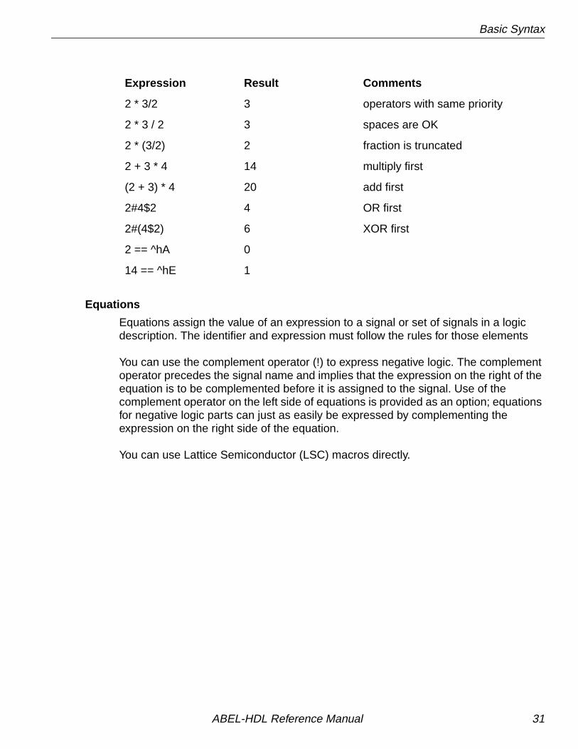
Equations
Equations assign the value of an expression to a signal or set of signals in a logicdescription. The identifier and expression must follow the rules for those elements
You can use the complement operator (!) to express negative logic. The complementoperator precedes the signal name and implies that the expression on the right of theequation is to be complemented before it is assigned to the signal. Use of thecomplement operator on the left side of equations is provided as an option; equationsfor negative logic parts can just as easily be expressed by complementing theexpression on the right side of the equation.
You can use Lattice Semiconductor (LSC) macros directly.
Expression Result Comments
2 * 3/2 3 operators with same priority
2 * 3 / 2 3 spaces are OK
2 * (3/2) 2 fraction is truncated
2 + 3 * 4 14 multiply first
(2 + 3) * 4 20 add first
2#4$2 4 OR first
2#(4$2) 6 XOR first
2 == ^hA 0
14 == ^hE 1
ABEL-HDL Reference Manual 31
Basic Syntax
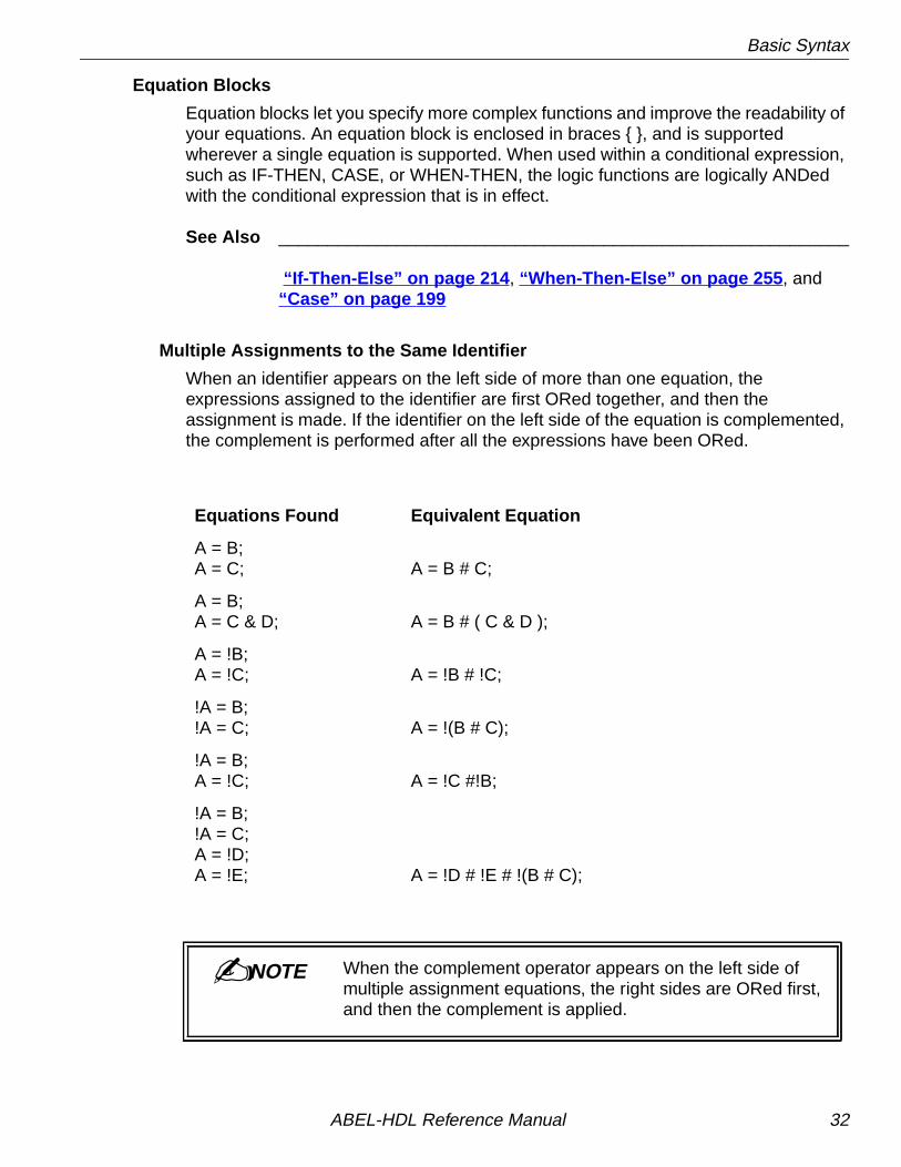
Equation Blocks
Equation blocks let you specify more complex functions and improve the readability ofyour equations. An equation block is enclosed in braces { }, and is supportedwherever a single equation is supported. When used within a conditional expression,such as IF-THEN, CASE, or WHEN-THEN, the logic functions are logically ANDedwith the conditional expression that is in effect.
See Also __________________________________________________________
“If-Then-Else” on page 214, “When-Then-Else” on page 255, and“Case” on page 199
Multiple Assignments to the Same Identifier
When an identifier appears on the left side of more than one equation, theexpressions assigned to the identifier are first ORed together, and then theassignment is made. If the identifier on the left side of the equation is complemented,the complement is performed after all the expressions have been ORed.
Equations Found Equivalent Equation
A = B;A = C; A = B # C;
A = B;A = C & D; A = B # ( C & D );
A = !B;A = !C; A = !B # !C;
!A = B;!A = C; A = !(B # C);
!A = B;A = !C; A = !C #!B;
!A = B;!A = C;A = !D;A = !E; A = !D # !E # !(B # C);
✍ NOTE When the complement operator appears on the left side ofmultiple assignment equations, the right sides are ORed first,and then the complement is applied.
ABEL-HDL Reference Manual 32

Basic Syntax
SetsA set is a collection of signals and constants. Any operation applied to a set is appliedto each element in the set. Sets simplify ABEL-HDL logic descriptions and testvectors by allowing groups of signals to be referenced with one name.
For example, you could collect the outputs (B0-B7) of an eight-bit multiplexer into aset named MULTOUT, and the three selection lines into a set named SELECT. Youcould then define the multiplexer in terms of MULTOUT and SELECT rather thanindividual input and output bits.
A set is represented by a list of constants and signals separated by commas or therange operator (..) and surrounded by brackets. The sets MULTOUT and SELECTwould be defined as follows:
MULTOUT = [B0,B1,B2,B3,B4,B5,B6,B7]SELECT = [S2,S1,S0]
The above sets could also be expressed by using the range operator; for example,
MULTOUT = [B0..B7]SELECT = [S2..S0]
Identifiers used to delimit a range must have compatible names: they must begin withthe same alphabetical prefix and have a numerical suffix. Range identifiers can alsodelimit a decrementing range or a range which appears as one element of a largerset as shown below:
[A7..A0] "decrementing range[Q1,Q2,.X.,A10..A7] "range within a larger set
The brackets are required to delimit the set. ABEL-HDL source file sets are notmathematical sets.
Set Indexing
Set indexing allows you to access elements within a set. The following example usesset indexing to assign four elements of a 16-bit set to a smaller set.
declarations Set1 = [f15..f0]; Set2 = [q3..q0];
equations
Set2 := Set1[7..4];
The numeric values used for defining a set index refer to the bit positions of the set,with 0 being the least significant (left-most) element in the set. So Set1[7..4] is Set1,values f8 to f11.
ABEL-HDL Reference Manual 33

Basic Syntax
If you are indexing into a set to access a single element, then you can use thefollowing syntax:
declarations out1 pin istype 'com'; Set1 = [f15..f0];
equations
out1 = Set1[4] == 1;
In this example, a comparator operator (==) was used to convert the single-elementset (Set1[4]) into a bit value (equivalent to f4).
See also “@Setsize — Set Indexing.”
Set Operations
Most operators can be applied to sets, with the operation performed on each elementof the set, sometimes individually and sometimes according to the rules of Booleanalgebra. Table 1-8 lists the operators you can use with sets. This section describeshow these operators are applied to sets.
Two-set Operations
For operations involving two or more sets, the sets must have the same number ofelements. The expression “[a,b]+[c,d,e]” is not supported because the sets havedifferent numbers of elements.
For example, the Boolean equation
Chip_Sel = A15 & !A14 & A13;
represents an address decoder where A15, A14 and A13 are the three high-order bitsof a 16-bit address. The decoder can easily be implemented with set operations.First, a constant set that holds the address lines is defined so the set can bereferenced by name. This definition is done in the constant declaration section of amodule.
The declaration is
Addr = [A15,A14,A13];
which declares the constant set Addr. The equation
Chip_Sel = Addr == [1,0,1];
is functionally equivalent to
Chip_Sel = A15 & !A14 & A13;
ABEL-HDL Reference Manual 34

Basic Syntax
If Addr is equal to [1,0,1], meaning that A15 = 1, A14 = 0 and A13 = 1, then Chip_Selis set to true. The set equation could also have been written as
Chip_Sel = Addr == 5;
because 101 binary equals 5 decimal.
In the example above, a special set with the high-order bits of the 16-bit address wasdeclared and used in the set operation. The full address could be used and the samefunction arrived at in other ways, as shown below:
Example 1
" declare some constants in declaration sectionAddr = [a15..a0];X = .X.; "simplify notation for don't care constantChip_Sel = Addr == [1,0,1,X,X,X,X,X,X,X,X,X,X,X,X];
Example 2
" declare some constants in declaration sectionAddr = [a15..a0];X =.X.;Chip_Sel = (Addr >= ^HA000) & (Addr <= ^HBFFF);
Both solutions presented in these two examples are functionally equivalent to theoriginal Boolean equation and to the first solution in which only the high order bits arespecified as elements of the set (Addr = [a15, a14, a13]) .
Set Assignment and Comparison
Values and sets of values can be assigned and compared to a set. Supported setoperations are given in Table 1-8. For example,
sigset = [1,1,0] & [0,1,1];
results in sigset being assigned the value, [0,1,0]. The set assignment
[a,b] = c & d;
is the same as the two assignments
a = c & d;b = c & d;
Numbers in any representation can be assigned or compared to a set. The precedingset equation could have been written as
sigset = 6 & 3;
ABEL-HDL Reference Manual 35

Basic Syntax
When numbers are used for set assignment or comparison, the number is convertedto its binary representation and the following rules apply:
■ the number of significant bits in the binary representation of a number is greaterthan the number of elements in a set, the bits are truncated on the left.
■ If the number of significant bits in the binary representation of a number is lessthan the number of elements in a set, the number is padded on the left withleading zeroes.
Thus, the following two assignments are equivalent:
[a,b] = ^B101011; "bits truncated to the left[a,b] = ^B11;
And so are these two:
[d,c] = ^B01;[d,c] = ^B1; "compiler will add leading zero
Table 1-8. Supported Set Operations
Operator Example Description
= A = 5 combinational assignment
:= A := [1,0,1] registered assignment
! !A NOT: ones complement
& A & B AND
# A # B OR
$ A $ B XOR: exclusive OR
!$ A!$B XNOR: exclusive NOR
- -A negate
- A-B subtraction
++ A+B addition
== A==B equal
!= A!=B not equal
< A<B less than
<= A<=B less than or equal
> A>B greater than
>= A>=B greater than or equal
ABEL-HDL Reference Manual 36

Basic Syntax
Set Evaluation
How an operator is performed with a set may depend on the types of arguments theoperator uses. When a set is written [a , b , c , d ] , “a” is the MOST significantbit and “d” is the LEAST significant bit.
The result, when most operators are applied to a set, is another set. The result of therelational operators (==, !=, >, >=, <, <=) is a value: TRUE (all ones) or FALSE (allzeros), which is truncated or padded to as many bits as needed. The width of theresult is determined by the context of the relational operator, not by the width of thearguments.
The different contexts of the AND (&) operator and the semantics of each usage aredescribed below.
signal & signala & b
This is the most straightforward use. The expression isTRUE if both signals are TRUE.
signal & numbera & 4
The number is converted to binary and the leastsignificant bit is used. The expression becomes a & 0,then is reduced to 0 (FALSE).
signal & seta & [x, y, z]
The signal is distributed over the elements of the set tobecome [a & x, a & y, a & z]
set & set[a, b] & [x, y]
The sets are ANDed bit-wise resulting in: [a & x, b & y].An error is displayed if the set widths do not match.
set & number[a, b, c] & 5
The number is converted to binary and truncated orpadded with zeros to match the width of the set. Thesequence of transformations is[a, b, c] & [1, 0, 1][a & 1, b & 0, c & 1][a, 0, c]
number & number9 & 5
The numbers are converted to binary, ANDed together,then truncated or padded.
ABEL-HDL Reference Manual 37

Basic Syntax
Example Equations
select = [a15..a0] == ^H80FF
select (signal) is TRUE when the 16-bit address bus has the hex value 80FF.Relational operators always result in a single bit.
[sel1, sel0] = [a3..a0] > 2
The width of sel and a are different, so the 2 is expanded to four bits (of binary) tomatch the size of the a set. Both sel1 and sel2 are true when the value of the four alines (taken as a binary number) is greater than 2.
The result of the comparison is a single-bit result which is distributed to bothmembers of the set on the output side of the equation.
[out3..out0] = [in3..in0] & enab
If enab is TRUE, then the values on in0 through in3 are seen on the out0 throughout3 outputs. If enab is FALSE, then the outputs are all FALSE.
Set Operation Rules
Set operations are applied according to Boolean algebra rules. Uppercase letters areset names, and lowercase letters are elements of a set. The letters k and n aresubscripts to the elements and to the sets. A subscript following a set name(uppercase letter) indicates how many elements the set contains. So Ak indicates thatset A contains k elements. ak-1 is the (k-1)th element of set A. a1 is the first elementof set A.
ABEL-HDL Reference Manual 38

Basic Syntax
Limitations/ Restrictions on Sets
If you have a set assigned to a single value, the value will be padded with 0s and thenapplied to the set. For example,
[A1,A2,A3] = 1
is equivalent to
A1 = 0A2 = 0A3 = 1
which may not be the intended result. If you want 1 assigned to each member of theset, you would need binary 111 or decimal 7.
Expression Is Evaluated As...
!Ak [!ak, !ak-1, ..., !a1]
-Ak !Ak + 1
Ak.OE [ak.OE, ak-1.OE, ..., a1.OE]
Ak & Bk [ak & bk, ak-1 & bk-1, ..., a1 & b1]
Ak # Bk [ak # bk, ak-1 # bk-1, ..., a1 # b1]
Ak $ Bk [ak $ bk, ak-1 $ bk-1, ..., a1 $ b1]
Ak !$ Bk [ak !$ bk, ak-1 !$ bk-1, ..., a1 !$ b1]
Ak == Bk (ak == bk) & (ak-1 == bk-1) & ... & (a1 == b1)
Ak != Bk (ak != bk) # (ak-1 != bk-1) # ... # (a1 != b1)
Ak + Bk Dk
where:dn is evaluated as an $ bn $ cn-1
cn is evaluated as (an $ bn) # (an & cn-1) # (bn & cn-1)c0 is evaluated as 0
Ak - Bk Ak + (-Bk)
Ak < Bk ck
where:cn is evaluated as (!an & (bn # cn-1) # an & bn & cn-1)!= 0c0 is evaluated as 0
ABEL-HDL Reference Manual 39

Basic Syntax
The results of using an operator depend on the sequence of evaluation. Withoutparentheses, operations are performed from left to right. Consider the following twoequations. In the first, the constant 1 is converted to a set; in the second, the 1 istreated as a single bit.
Equation 1:
The first operation is [a, b] & 1 , so 1 is converted to a set [0, 1].
[x1, y1] = [a, b] & 1 & d = ([a, b] & 1 ) & d = ([a, b] & [0, 1]) & d = ([a & 0, b & 1]) & d = [ 0 , b ] & d = [0 & d, b & d] = [0, b & d]
x1 = 0 y1 = b & d
Equation 2:
The first operation is 1 & d, so 1 is treated as a single bit.
[x2,y2] = 1 & d & [a, b]= (1 & d) & [a, b]= d & [a, b]= [d & a, d & b]
x2 = a & dy2 = b & d
If you are unsure about the interpretation of an equation, try the following:
■ Fully parenthesize your equation. Errors can occur if you are not familiar with theprecedence rules in Table 1-7.
■ Write out numbers as sets of 1s and 0s instead of as decimal numbers. If thewidth is not what you expected, you will get an error message.
ABEL-HDL Reference Manual 40
Basic Syntax
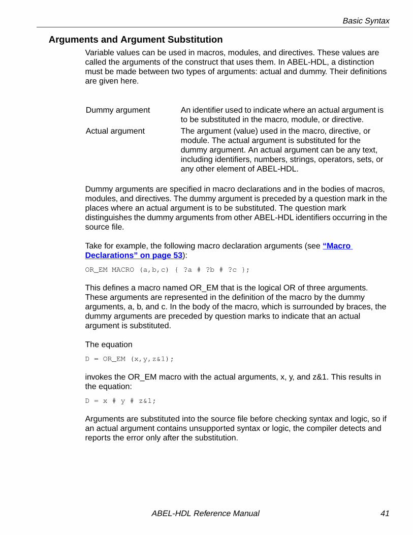
Arguments and Argument SubstitutionVariable values can be used in macros, modules, and directives. These values arecalled the arguments of the construct that uses them. In ABEL-HDL, a distinctionmust be made between two types of arguments: actual and dummy. Their definitionsare given here.
Dummy arguments are specified in macro declarations and in the bodies of macros,modules, and directives. The dummy argument is preceded by a question mark in theplaces where an actual argument is to be substituted. The question markdistinguishes the dummy arguments from other ABEL-HDL identifiers occurring in thesource file.
Take for example, the following macro declaration arguments (see “MacroDeclarations” on page 53):
OR_EM MACRO (a,b,c) { ?a # ?b # ?c };
This defines a macro named OR_EM that is the logical OR of three arguments.These arguments are represented in the definition of the macro by the dummyarguments, a, b, and c. In the body of the macro, which is surrounded by braces, thedummy arguments are preceded by question marks to indicate that an actualargument is substituted.
The equation
D = OR_EM (x,y,z&1);
invokes the OR_EM macro with the actual arguments, x, y, and z&1. This results inthe equation:
D = x # y # z&1;
Arguments are substituted into the source file before checking syntax and logic, so ifan actual argument contains unsupported syntax or logic, the compiler detects andreports the error only after the substitution.
Dummy argument An identifier used to indicate where an actual argument isto be substituted in the macro, module, or directive.
Actual argument The argument (value) used in the macro, directive, ormodule. The actual argument is substituted for thedummy argument. An actual argument can be any text,including identifiers, numbers, strings, operators, sets, orany other element of ABEL-HDL.
ABEL-HDL Reference Manual 41

Basic Syntax
Spaces in Arguments
Actual arguments are substituted exactly as they appear, so any spaces (blanks) inactual arguments are passed to the expression. In most cases, spaces do not affectthe interpretation of the macro. The exception is in functions that compare characterstrings, such as @IFIDEN and IFNIDEN. For example, the macro
iden macro(a,b) {@ifiden(?a,?b){@message 'they are the same';};};
compares the actual arguments and prints the message if they are identical. If youenter the macro with spaces in the actual arguments:
iden(Q1, Q1);
The value is false because the space is passed to the macro.
Argument Guidelines
■ Dummy arguments are place holders for actual arguments.
■ A question mark preceding the dummy argument indicates that an actualargument is to be substituted.
■ Actual arguments replace dummy arguments before the source file is checked forcorrectness.
■ Spaces in actual arguments are retained.
Further discussion and examples of argument use are given in Chapter 5,“Language Reference” under Module , Macro , and “@Directive — Directives.”
ABEL-HDL Reference Manual 42

Basic Structure
Basic StructureABEL-HDL source files can contain independent modules. Each module contains acomplete logic description of a circuit or subcircuit. Any number of modules can becombined into one source file and processed at the same time.
This section covers the basic elements that make up an ABEL-HDL source filemodule. A module can be divided into five sections:
■ Header
■ Declarations
■ Logic Description
■ Test Vectors
■ End
The elements of the source file are shown in the template in Figure 1-1. There arealso directives that can be included in any of the middle three sections. The sectionsare presented briefly, then each element is introduced. You can find completeinformation in Chapter 5, “Language Reference”
The following rules apply to module structure:
■ A module must contain only one header (composed of the Module statement andoptional Title and Options statements).
■ All other sections of a source file can be repeated in any order. Declarations mustimmediately follow either the header or the Declarations keyword.
■ No symbol (identifier) can be referenced before it is declared.
Header■ The Header Section can consist of the following elements:
■ Module (required)
■ Interface (lower level, optional)
■ Title
DeclarationsA Declarations Section can consist of the following elements:
■ Declarations Keyword
■ Interface and Functional Block Declarations
■ Signal Declarations (pin and node numbers optional)
■ Constant Declarations
■ Macro Declarations
■ Library Declarations
■ Device Declaration (one per module)
ABEL-HDL Reference Manual 43

Basic Structure
Figure 1-1. ABEL-HDL Module Structure
MODULEThe module statement names the module andindicates if dummy arguments are used.In lower-level modules, it can befollowed by an interface declaration.
ABEL-HDL Module
Module source3Title ’Example of a Source File’
Declarations in1, in2, in3, clk PIN ; all, none, other PIN ISTYPE ’reg’; in = [in1 .. in3]; out = [all, none, other];
Equations out.clk = clk; all := in1 & in2 & in3; none := !in1 & !in2 & !in3; other := (!in1 # !in2 # !in3) & ( in1 # in2 # in3)
Test_Vectors ([in, clk] -> [out] ([ 7, c ] -> 4 ; ([ 3, c ] -> 1 ;
End source3
He
ad
er
De
cla
ratio
ns
Lo
gic
De
scrip
tion
Te
stV
ect
ors
En
d
Bold denotes ABEL-HDL keywords
TITLEThe title statement can be used togive a title or description for themodule.
DECLARATIONSDeclarations declare lower-levelmodules, and associate nameswith functional block instances
macros, and sets. They alsodevices, pins, nodes, constants,
assign attributes with istype .
EQUATIONSYou can use Equations, StateDiagrams or Truth Tables todescribe your logic design.
TEST_VECTORSTest Vectors are used asstimulus for Functional Simulator
ENDThe end statement ends themodule.
or Timing Simulator.
ABEL-HDL Reference Manual 44

Basic Structure
Logic DescriptionYou can use one or more of the following elements to describe your design.
■ Equations
■ Truth Tables
■ State Diagrams
■ Fuses
■ XOR Factors
Test Vectors SectionTest vectors are used for Functional or Timing Simulation. A Test Vectors section canconsist of the following elements:
■ Test Vectors
■ Trace Statement
■ Test Script
End StatementA module is closed with the end statement:
■ End Statement
Other ElementsDirectives can be placed anywhere you need them:
■ Directives
ABEL-HDL Reference Manual 45

Header
Header
ModuleKeyword: module
The MODULE statement is required. It defines the beginning of the module and mustbe paired with an END statement. The MODULE statement also indicates whetherany module arguments are used.
InterfaceKeyword: interface
The INTERFACE statement is used in lower-level sources to indicate signals used inupper-level files. The interface statement is optional.
TitleKeyword: title
The title is optional. The title appears as a header in some output files.
DeclarationsThe declarations section of a module specifies the names and attributes of signalsused in the design, defines constants macros and states, declares lower-levelmodules and schematics, and optionally declares a device. Each module must haveat least one declarations section, and declarations affect only the module in whichthey are defined. There are several types of declaration statements:
■ Constant (see =)
■ Device
■ Hierarchy
■ Library
■ Macro
■ Signal (see Pin, Node and Istype)
■ State
■ State register
The syntax and use of each of these types is presented in Chapter 5, “LanguageReference.” Some are discussed briefly below.
ABEL-HDL Reference Manual 46

Declarations
Declarations KeywordKeyword: declarations
This keyword allows declarations (such as sets or other constants) in any part of thesource file.
Device DeclarationKeyword: device
device_id Device real_device ;
The DEVICE declaration is optional, and only one can be made per module. Itassociates a device identifier with a specific programmable logic device.
Hierarchy Declarations
Interface Declarations
Top-level Interface Declarations
Keyword: interface
low-level module_name Interface ( inputs [= value ] -> outputs :>bidirs ...)
The INTERFACE keyword declares lower-level modules that are used by the currentmodule. This declaration is used in conjunction with a FUNCTIONAL_BLOCKdeclaration for each instantiation of a module.
When you instantiate a functional block, you must map port names to signal nameswith equations. See “Functional_block” on page 208 for more information.
Lower-level Interface Declarations
Keyword: interface
Module module_nameInterface ( input/set =value . . . -> output/set :> bidir/set ) ;
Use the INTERFACE declaration in lower-level modules to assign a default port listand input values for the module when instantiated in higher-level ABEL-HDL sources.In the higher-level source, you must declare signals and sets in the same order andgrouping as given in the interface statement in the instantiated module.
The -> and :> delimiters are used to indicate the direction of each port of a functionalblock.
ABEL-HDL Reference Manual 47

Declarations
Functional_block Statement
Keyword: functional_block
Declarationsinstance_name Functional_block module_name ;
Equationsinstance_name . port_name = signal_name ;
Use a FUNCTIONAL_BLOCK declaration to instantiate a declared source within ahigher-level ABEL-HDL source. You must declare a source with an INTERFACEdeclaration before instantiating it with FUNCTIONAL_BLOCK.
▲ CAUTION Interface declarations cannot contain dot extensions. Ifyou need a specific dot extension across a sourceboundary (to resolve feedback ambiguities, for example),you must introduce an intermediate signal into thelower-level module to provide the connection to thehigher-level source. All dot extension equations for agiven output signal must be located in the ABEL-HDLmodule in which the signal is defined. No references tothat signal's dot extensions can be made outside of theABEL-HDL module.
ABEL-HDL Reference Manual 48

Declarations
Example of Functional Block Instantiation
To declare the two ABEL-HDL sources shown in Figure 1-2 would require thefollowing syntax:
module FUNC ; mod1 INTERFACE (i1 -> o1);
A FUNCTIONAL_BLOCK mod1; mod2 INTERFACE (i1 -> o1);
B FUNCTIONAL_BLOCK mod2; I pin ; O pin istype 'com';
Equations O = B.o1; B.i1 = A.o1; A.i1 = I;
end Func
Figure 1-2. Functional Block Instantiation
See Also _________________________________________________________
“Hierarchy in ABEL-HDL” on page 61
✍ NOTE The output of an equation must always be on the left side ofthe equations.
MODULE MOD 1 MODULE MOD2
i1 o1 i1 o1I O
ABEL-HDL Reference Manual 49

Declarations
Signal DeclarationsThe PIN and NODE declarations are made to declare signals used in the design, andoptionally to associate pin and/or node numbers with those signals. Actual pin andnode numbers do not have to be assigned until you want to map the design into adevice. Attributes can be assigned to signals within pin and node declarations withthe ISTYPE statement. Dot extensions can also be used in equations to preciselydescribe the signals; see “Dot Extensions” on page 53.
Pin Declarations
Keyword: pin
[ ! ] pin_id [,[ ! ] pin_id ...] Pin [ pin# [, pin# ] ][ISTYPE ' attributes ' ] ;
See Also ___________________________________________________________
“Attribute Assignment” on page 51“Using Active-low Declarations” on page 74
Node Declarations
Keyword: node
[ ! ] node_id [, [ ! ] node_id ...] Node [ node# [, node# ] ][ISTYPE ' attributes ' ] ;
See Also ________________________________________________________
“Attribute Assignment” on page 51“Using Active-low Declarations” on page 74
✍ NOTE Assigning pin numbers defines the particular pin-outsnecessary for the design. Pin numbers only limit the deviceselection to a minimum number of input and output pins. Pinnumber assignments can be changed later by the compiler.
ABEL-HDL Reference Manual 50

Declarations
Attribute Assignment
Keyword: istype
signal [, signal ]... Istype ' attributes ';
The ISTYPE statement defines attributes (characteristics) of signals for devices withprogrammable characteristics or when no device and pin/node number has beenspecified for a signal. Even when a device has been specified, using attributes willmake it more likely that the design operates consistently if the device is changed later.ISTYPE can be used after pin or node declarations.
Attributes may be entered in uppercase, lowercase, or mixed-case letters.
Table 1-9 summarizes the attributes. Each attribute is discussed in more detail inChapter 5, “Language Reference” under Istype.
Table 1-9. Attributes
Dot Ext.Arch.Indep. Description
'buffer' No Inverter in Target Device.
'collapse' Collapse (remove) this signal. 1
'com' ✓ Combinational output.
'dc' ✓ Unspecified logic is don't care. 2
'invert' Inverter in Target Device.
'keep' Do not collapse this signal from equations. 1
'neg' ✓ Unspecified logic is 1. 2
'pos' ✓ Unspecified logic is 0. 2
'retain' ✓ Do not minimize this output. Preserveredundant product terms. 3
'reg' ✓ Clocked Memory Element.
'reg_d' D Flip-flop Clocked Memory Element.
'reg_g' D Flip-flop Gated Clock Memory Element.
'reg_jk' JK Flip-flop Clocked Memory Element.
'reg_sr' SR Flip-flop Clocked Memory Element.
'reg_t' T Flip-flop Clocked Memory Element.
'xor' XOR Gate in Target Device.
ABEL-HDL Reference Manual 51

Declarations
1. If neither 'keep' nor 'collapse' is specified, the compiler program can keep orcollapse the signal, as needed, to optimize the circuit.
2. The 'dc,' 'neg,' and 'pos' attributes are mutually exclusive.
3. The 'retain' attribute only controls optimization performed by ABEL-HDL CompileLogic. To preserve redundant product terms, you must also specify no reductionfor the Reduce Logic and fitting (place and route) programs.
Constant Declarations
Keyword: =
id [, id ]... = expr [, expr ]... ;
A constant is an identifier that retains a constant value in a module and is specifiedwith the = sign. Constant declarations must be in a declarations section or after a@Const directive.
See Also ________________________________________________________
“Constants” on page 19
Symbolic State DeclarationsThe STATE_REGISTER and STATE declarations are made to declare a symbolicstate machine name, and to declare symbolic state names.
See Also ___________________________________________________________
“State Descriptions” on page 56
State_register Declarations
Keyword: state_register
statereg_id State_register [Istype 'attributes'];
State Declarations
Keyword: state
state_id [, state_id...] State [state_value[, state_value...]];
ABEL-HDL Reference Manual 52

Logic Description
Macro Declarations
Keyword: macro
macro_id Macro [( dummy_arg [, dummy_arg ]... )] { block } ;
The MACRO declaration statement defines a macro. Use macros to include functionsin a source file without repeating the code.
Library Declaration
Keyword: library
Library ' name' ;
The LIBRARY statement extracts the contents of the indicated file from theABEL-HDL library and inserts it into your file.
Logic DescriptionOne or more of the following elements can be used to describe your design.
■ Equations
■ Truth Tables
■ State Descriptions
■ Fuses
■ XOR Factors
In addition, dot extensions (like Istype attributes in the Declarations section) enableyou to more precisely describe the behavior of a circuit in a logic description that maybe targeted to a variety of different devices.
Dot Extensions
Syntax signal_name . ext
Dot extensions can be specific for certain devices (device-specific) or generalized forall devices (architecture-independent). Device-specific dot extensions are used withdetailed syntax; architecture-independent dot extensions are used with pin-to-pinsyntax. Detailed and pin-to-pin syntax is described in more detail in Chapter 2,“Design Considerations.” Dot extensions can be applied in complex languageconstructs such as nested sets or complex expressions.
The ABEL-HDL dot extensions are listed in Table 1-10.
ABEL-HDL Reference Manual 53

Logic Description
Table 1-10. Dot Extensions
Dot Extensions Description
Pin-to-Pin Syntax, Architecture-independent
.ACLR *Asynchronous clear
.ASET *Asynchronous set
.CLK Clock input to an edge-triggered flip-flop
.CLR *Synchronous clear
.COM *Combinational feedback normalized to the pin value
.FB Register feedback
.OE Output enable
.PIN Pin feedback
.SET *Synchronous set
Detailed Syntax, Device-specific
.AP Asynchronous register preset
.AR Asynchronous register reset
.CE Clock-enable input to a gated-clock flip-flop
.D Data input to a D-type flip-flop
.FC Flip-flop mode control
.J J input to a JK-type flip-flop
.K K input to a JK-type flip-flop
.LD Register load input
.LE Latch-enable input to a latch
.LH Latch-enable (high) to a latch
.PR Register preset
.Q Register feedback
.R R input to an SR-type flip-flop
.RE Register reset
.S S input to an SR-type flip-flop
.SP Synchronous register preset
ABEL-HDL Reference Manual 54

Logic Description
Equations
Keyword: equations
Equations[ WHEN condition THEN ] [ ! ] element=expression;
[ ELSE equation ];or
[ WHEN condition THEN ] equation; [ ELSE equation];inst_name LSC_macro_name (port_definition);
The EQUATIONS statement defines the beginning of a group of equations thatspecify the logic functions of a device.
See Also ___________________________________________________________
“Operators, Expressions, and Equations” on page 24“When-Then-Else” on page 255
.SR Synchronous register reset
.T T input to a T-type (toggle) flip-flop
* The .CLR , .ACLR, .SET, .ASET, and .COM dot extensions are not recognizedby device fitters released prior to ABEL 5.0. If you are using a fitter that does notsupport these reset/preset dot extensions, specify istype 'invert' or istype 'buffer'and the compiler converts the new dot extensions to .SP, .AP, .SR , .AR , and .D ,respectively.
Table 1-10. Dot Extensions (Continued)
Dot Extensions Description
ABEL-HDL Reference Manual 55
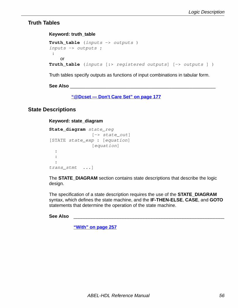
Logic Description
Truth Tables
Keyword: truth_table
Truth_table ( inputs -> outputs )inputs -> outputs ; :
orTruth_table ( inputs [:> registered outputs ] [-> outputs ] )
Truth tables specify outputs as functions of input combinations in tabular form.
See Also ________________________________________________________
“@Dcset — Don't Care Set” on page 177
State Descriptions
Keyword: state_diagram
State_diagram state_reg[-> state_out ]
[STATE state_exp : [ equation ][ equation ]
: : :trans_stmt ...]
The STATE_DIAGRAM section contains state descriptions that describe the logicdesign.
The specification of a state description requires the use of the STATE_DIAGRAMsyntax, which defines the state machine, and the IF-THEN-ELSE, CASE, and GOTOstatements that determine the operation of the state machine.
See Also __________________________________________________________
“With” on page 257
ABEL-HDL Reference Manual 56

Logic Description
Fuse Declarations
Keyword: fuses
Fusesfuse_number = fuse value ;
orfuse_number_set = fuse value ;
The FUSES section explicitly declares the state of fuses in the associated device. Adevice must be declared before a fuses declaration.
XOR Factors
Keyword: XOR_Factors
XOR_factorssignal name = xor_factors
The XOR_FACTORS section allows you to specify a Boolean expression that is to befactored out of and XORed with the sum-of-products reduced equations. Thisfactoring can result in smaller reduced equations when the design is implemented ina device featuring XOR gates.
ABEL-HDL Reference Manual 57

Test Vectors Section
Test Vectors Section
Test Vectors
Keyword: test_vector
Test_vectors [ note ]( inputs -> outputs )[ invalues -> outvalues ; ] ...
Test vectors specify the expected operation of a logic device by defining its outputs asa function of its inputs.
Trace Statement
Keyword: trace
Trace ( inputs -> outputs ) ;
The TRACE statement limits which inputs and outputs are displayed in the simulationreport.
End Statement
Keyword: end
End module_name
The END statement ends the module and is required.
ABEL-HDL Reference Manual 58
Other Elements
Other Elements
Directives
Keyword: @ directive
@directive [options]
Directives provide options that control the contents or processing of a source file.Sections of ABEL-HDL source code can be included conditionally, code can bebrought in from another file, and messages can be printed during processing.
Some directives take arguments that determine how the directive is processed.These arguments can be actual arguments or dummy arguments preceded by aquestion mark. The rules applying to actual and dummy arguments are presentedunder “Arguments and Argument Substitution” on page 41.
Available directives are listed below. See @ in Chapter 5, “Language Reference”for complete information.
@ALTERNATE@CARRY@CONST@DCSET@DCSTATE@EXPR@EXIT@IF@IFB@IFDEF@IFIDEN@IFNB
@IFNDEF@IFNIDEN@INCLUDE@IRP@IRPC@MESSAGE@ONSET@PAGE@RADIX@REPEAT@SETSIZE@STANDARD
ABEL-HDL Reference Manual 59

Chapter 2 Design Considerations
This chapter discusses issues you need to consider when you create a design withABEL-HDL. The topics covered are listed below:
■ Hierarchy in ABEL-HDL
■ Pin-to-Pin Architecture-independent Language Features
■ Pin-to-Pin vs. Detailed Descriptions for Registered Designs
■ Using Active-low Declarations
■ Polarity Control
■ Istypes and Attributes
■ Flip-flop Equations
■ Feedback Considerations — Using Dot Extensions
■ @Dcset Considerations and Precautions
■ Exclusive OR Equations
■ State Machines
■ Using Complement Arrays
■ Accessing Device-specific and Complex Architectural Elements
ABEL-HDL Reference Manual 60

Hierarchy in ABEL-HDL
Hierarchy in ABEL-HDLYou use hierarchy declarations in an upper-level ABEL-HDL source to refer to(instantiate) an ABEL-HDL module.
To instantiate an ABEL-HDL module in the lower-level module (optional):
1. Identify lower-level I/O Ports (signals) with an INTERFACE statement.
To instantiate an ABEL-HDL module in the top-level source:
2. Declare the lower-level module with an Interface declaration.
3. Instantiate the lower-level module with Functional_block declarations.
Instantiating a Lower-level Module in an ABEL-HDL Source
Identifying I/O Ports in the Lower-level Module
The way to identify an ABEL-HDL module's input and output ports is to place anINTERFACE statement immediately following the MODULE statement. TheINTERFACE statement defines the ports in the lower-level module that are used bythe top-level source.
You must declare all input pins in the ABEL-HDL module as ports, and you canspecify default values of 0, 1, or Don't-care.
You do not have to declare all output pins as ports. Any undeclared outputs becomeNo Connects or redundant nodes. Redundant nodes can later be removed from thedesigns during post-link optimization.
The following source fragment is an example of a lower-level INTERFACE statement.
module lowerinterface (a=0, [d3..d0]=7 -> [z0..z7]) ;title 'example of lower-level interface statement ' ...
This statement identifies input a, d3, d2, d1 and d0 with default values, and outputsz0 through z7. For more information, see “Interface (lower-level)” on page 219 .
✍ NOTE Hierarchy declarations are not required when instantiating anABEL-HDL module in an ispDesignExpert schematic. Forinstructions on instantiating lower-level modules in schematics,refer to the online help.
ABEL-HDL Reference Manual 61

Hierarchy in ABEL-HDL
Specifying Signal Attributes
Attributes specified for pins in a lower-level module are propagated to the higher-levelsource. For example, a lower-level pin with an 'invert' attribute affects the higher-levelsignal wired to that pin (it affects the pin's preset, reset, preload, and power-up value).
Output Enables (OE)
Connecting a lower-level tri-state output to a higher-level pin results in the outputenable being specified for the higher-level pin. If another OE is specified for thehigher-level pin, it is flagged as an error. Since most tri-state outputs are used asbidirectionals, it might be important to keep the lower-level OE.
Buried Nodes
Buried nodes in lower-level sources are handled as follows:
Declaring Lower-level Modules in the Top-level Source
To declare a lower-level module, you match the lower-level module's interfacestatement with an interface declaration. For example, to declare the lower-levelmodule given above, you would add the following declaration to your upper-levelsource declarations:
lower interface (a, [d3..d0] -> [z0..z7]) ;
You could specify different default values if you want to override the values given inthe instantiated module, otherwise the instantiated module must exactly match thelower-level interface statement. See “Interface (top-level)” on page 217 for moreinformation.
Dangling Nodes Lower-level nodes that do not fanout arepropagated to the higher-level module and becomedangling nodes. Optimization may remove danglingnodes.
Combinational nodes Combinational nodes in a lower-level modulebecome collapsible nodes in the higher-levelmodule.
Registered nodes Registered nodes are preserved with hierarchicalnames assigned to them.
ABEL-HDL Reference Manual 62

Hierarchy in ABEL-HDL
Instantiating Lower-level Modules in Top-level Source
Use a FUNCTIONAL_BLOCK declaration in an top-level ABEL-HDL source toinstantiate a declared lower-level module and make the ports of the lower-levelmodule accessible in the upper-level source. You must declare sources with anINTERFACE declaration before you instantiate them.
To instantiate the module declared above, add an interface declaration and signaldeclarations to your top-level declarations, and add port connection equations to yourtop-level equations, as shown in the source fragment below:
DECLARATIONS low1 FUNCTIONAL_BLOCK lower ; zed0..zed7 pin ; "upper-level inputs atop pin istype 'reg,buffer'; "upper-level output d3..d0 pin istype 'reg,buffer';"upper-level outputsEQUATIONS atop = low1.a; "wire this source's outputs [d3..d0] = low1.[d3..d0] ; "to lower-level inputs low1.[z0..z7] = [zed0..zed7]; "wire this source's inputs to
"lower-level outputs
See “Functional_block” on page 208 for more information.
Hierarchy and Retargeting and Fitting
Redundant Nodes
When you link multiple sources, some unreferenced nodes may be generated. Thesenodes usually originate from lower-level outputs that are not being used in the top-level source. For example, when you use a 4-bit counter as a 3-bit counter. The mostsignificant bit of the counter is unused and can be removed from the design to savedevice resources. This step also removes trivial connections. In the followingexample, if out1 is a pin and t1 is a node:
out1 = t1;t1 = a86;
would be mapped to
out1 = a86;
ABEL-HDL Reference Manual 63

Node Collapsing
Merging FeedbacksLinking multiple modules can produce signals with one or more feedback types, suchas .FB and .Q . You can tell the optimizer to combine these feedbacks to help thefitting process.
Post-linked OptimizationIf your design has a constant tied to an input, you can re-optimize the design. Re-optimizing may further reduce the product terms count.
For example, if you have the equation
out = i0 & i1 || !i0 & i2;
and i0 is tied to 1, the resulting equation would be simplified to
out = i1;
Node CollapsingAll combinational nodes are collapsible by default. Nodes that are to be collapsed (ornodes that are to be preserved) are flagged through the use of signal attributes in thelanguage. The signal attributes are:
Istype 'keep' Do not collapse this node.
'collapse' Collapse this node.
Collapsing provides multi-level optimization for combinational logic. Designs witharithmetic and comparator circuits generally generate a large number of productterms that will not fit to any programmable logic device. Node collapsing allows you todescribe equations in terms of multi-level combinational nodes, then collapse thenodes into the output until it reaches the product term you specify. The result is anequation that is optimized to fit the device constraints.
ABEL-HDL Reference Manual 64

Pin-to-pin Language Features
Selective CollapsingIn some instances you may want to prevent the collapsing of certain nodes. Forexample, some nodes may help in the simulation process. You can specify nodes youdo not want collapsed as Istype 'keep' and the optimizer will not collapse them.
Pin-to-pin Language FeaturesABEL-HDL is a device-independent language. You do not have to declare a device orassign pin numbers to your signals until you are ready to implement the design into adevice. However, when you do not specify a device or pin numbers, you need tospecify pin-to-pin attributes for declared signals.
Because the language is device-independent, the ABEL-HDL compiler does not havepredetermined device attributes to imply signal attributes. If you do not specify signalattributes or other information (such as the dot extensions, which are described later),your design might not operate consistently if you later transfer it to a different targetdevice.
Device-independence vs. Architecture-independenceThe requirement for signal attributes does not mean that a complex design mustalways be specified with a particular device in mind. You may still have to understandthe differences between, for example, a GAL16LV8 and an ispLSI1032E, but you donot have to specify a particular device when describing your design.
Attributes and dot extensions help you refine your design to work consistently whenmoving from one class of device architecture to another; for example from deviceshaving inverted outputs to those with a particular kind of reset/preset circuitry.However, the more you refine your design, using these language features, the morerestrictive your design becomes in terms of the number of device architectures forwhich it is appropriate.
Signal AttributesSignal attributes remove ambiguities that occur when no specific device architectureis declared. If your design does not use device-related attributes (either implied by aDEVICE statement or expressed in an ISTYPE statement), it may not operate thesame way when targeted to different device architectures. See “Pin” on page 235,“Node” on page 233, and “Istype _ Attribute Declarations” on page 222 .
ABEL-HDL Reference Manual 65

Pin-to-pin vs. Detailed Descriptions for Registered Designs
Signal Dot ExtensionsSignal dot extensions, like attributes, enable you to more precisely describe thebehavior of a circuit that may be targeted to different architectures. Dot extensionsremove the ambiguities in equations.
Refer to “Dot Extensions and Architecture-independence” on page 80 or “. ext— Dot Extensions” on page 158 for more information.
Pin-to-pin vs. Detailed Descriptions for Registered DesignsYou can use ABEL-HDL assignment operators when you write high-level equations.The = operator specifies a combinational assignment, where the design is writtenwith only the circuit's inputs and outputs in mind. The := assignment operatorspecifies a registered assignment, where you must consider the internal circuitelements (such as output inverters, presets and resets) related to the memoryelements (typically flip-flops). The semantics of these two assignment operators arediscussed below.
Using := for Pin-to-pin DescriptionsThe := implies that a memory element is associated with the output defined by theequation. For example, the equation
Q1 := !Q1 # Preset;
implies that Q1 will hold its current value until the memory element associated withthat signal is clocked (or unlatched, depending on the register type). This equation isa pin-to-pin description of the output signal Q1. The equation describes the signal'sbehavior in terms of desired output pin values for various input conditions. Pin-to-pindescriptions are useful when describing a circuit that is completely architecture-independent.
Language elements that are useful for pin-to-pin descriptions are the ":=" assignmentoperator, and the .CLK , .OE, .FB , .CLR , .ACLR, .SET, .ASET , and .COM dotextensions described in Chapter 5, “Language Reference.” These dot extensionshelp resolve circuit ambiguities when describing architecture-independent circuits.
ABEL-HDL Reference Manual 66
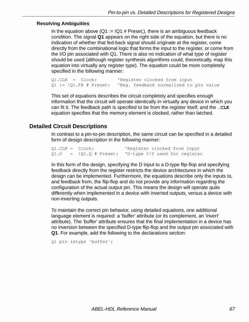
Pin-to-pin vs. Detailed Descriptions for Registered Designs
Resolving Ambiguities
In the equation above (Q1 := !Q1 # Preset;), there is an ambiguous feedbackcondition. The signal Q1 appears on the right side of the equation, but there is noindication of whether that fed-back signal should originate at the register, comedirectly from the combinational logic that forms the input to the register, or come fromthe I/O pin associated with Q1. There is also no indication of what type of registershould be used (although register synthesis algorithms could, theoretically, map thisequation into virtually any register type). The equation could be more completelyspecified in the following manner:
Q1.CLK = Clock; "Register clocked from inputQ1 := !Q1.FB # Preset; "Reg. feedback normalized to pin value
This set of equations describes the circuit completely and specifies enoughinformation that the circuit will operate identically in virtually any device in which youcan fit it. The feedback path is specified to be from the register itself, and the .CLKequation specifies that the memory element is clocked, rather than latched.
Detailed Circuit DescriptionsIn contrast to a pin-to-pin description, the same circuit can be specified in a detailedform of design description in the following manner:
Q1.CLK = Clock; "Register clocked from inputQ1.D = !Q1.Q # Preset; "D-type f/f used for register
In this form of the design, specifying the D input to a D-type flip-flop and specifyingfeedback directly from the register restricts the device architectures in which thedesign can be implemented. Furthermore, the equations describe only the inputs to,and feedback from, the flip-flop and do not provide any information regarding theconfiguration of the actual output pin. This means the design will operate quitedifferently when implemented in a device with inverted outputs, versus a device withnon-inverting outputs.
To maintain the correct pin behavior, using detailed equations, one additionallanguage element is required: a 'buffer' attribute (or its complement, an 'invert'attribute). The 'buffer' attribute ensures that the final implementation in a device hasno inversion between the specified D-type flip-flop and the output pin associated withQ1. For example, add the following to the declarations section:
Q1 pin istype 'buffer';
ABEL-HDL Reference Manual 67

Pin-to-pin vs. Detailed Descriptions for Registered Designs
Detailed Descriptions: Designing for Macrocells
One way to understand the difference between pin-to-pin and detailed descriptionmethods is to think of detailed descriptions as macrocell specifications. A macrocell isa block of circuitry normally (but not always) associated with a device's I/O pin.Figure 2-1 illustrates a typical macrocell associated with signal Q1.
Detailed descriptions are written for the various input ports of the macrocell (shown inFigure 2-1 with dot extension labels). Note that the macrocell features a configurableinversion between the Q output of the flip-flop and the output pin labeled Q1. If youuse this inverter (or select a device that features a fixed inversion), the behavior youobserve on the Q1 output pin will be inverted from the logic applied to (or observedon) the various macrocell ports, including the feedback port Q1.q .
Figure 2-1. Detail Macrocell
Pin-to-pin descriptions, on the other hand, allow you to describe your circuit in termsof the expected behavior on an actual output pin, regardless of the architecture of theunderlying macrocell. Figure 2-2 illustrates the pin-to-pin concept:
Q1.oe
O
FuseMux
1
Q1
AP
Q1.ap
Q1.d
Q1.clk
Q1.ar
Q1.q
Q1.pin
!Q1.pin
AR
CLK
D Q
ABEL-HDL Reference Manual 68

Pin-to-pin vs. Detailed Descriptions for Registered Designs
Figure 2-2. Pin-to-pin Macrocell
When pin-to-pin descriptions are written in ABEL-HDL, the "generic macrocell"shown above is synthesized from whatever type of macrocell actually exists in thetarget device.
Examples of Pin-to-pin and Detailed DescriptionsTwo equivalent module descriptions, one pin-to-pin and one detailed, are shownbelow for comparison:
Pin-to-pin Module Description
module Q1_1 Q1 pin istype 'reg'; Clock,Preset pin;
equations Q1.clk = Clock; Q1 := !Q1.fb # Preset;
test_vectors ([Clock,Preset] -> Q1) [ .c. , 1 ] -> 1; [ .c. , 0 ] -> 0; [ .c. , 0 ] -> 1; [ .c. , 0 ] -> 0; [ .c. , 1 ] -> 1; [ .c. , 1 ] -> 1;end
ABEL-HDL Reference Manual 69

Pin-to-pin vs. Detailed Descriptions for Registered Designs
Detailed Module Description
module Q1_2 Q1 pin istype 'reg_D,buffer'; Clock,Preset pin;
equations Q1.CLK = Clock; Q1.D = !Q1.Q # Preset;
test_vectors ([Clock,Preset] -> Q1) [ .c. , 1 ] -> 1; [ .c. , 0 ] -> 0; [ .c. , 0 ] -> 1; [ .c. , 0 ] -> 0; [ .c. , 1 ] -> 1; [ .c. , 1 ] -> 1;end
The first description can be targeted into virtually any device (if register synthesis anddevice fitting features are available), while the second description can be targetedonly to devices featuring D-type flip-flops and non-inverting outputs.
To implement the second (detailed) module in a device with inverting outputs, thesource file would need to be modified in the following manner:
Detailed Module with Inverted Outputsmodule Q1_3 Q1 pin istype 'reg_D,invert'; Clock,Preset pin;equations Q1.CLK = Clock; !Q1.D = Q1.Q # Preset;test_vectors ([Clock,Preset] -> Q1) [ .c. , 1 ] -> 1; [ .c. , 0 ] -> 0; [ .c. , 0 ] -> 1;
[ .c. , 0 ] -> 0; [ .c. , 1 ] -> 1; [ .c. , 1 ] -> 1;end
In this version of the module, the existence of an inverter between the output of theD-type flip-flop and the output pin (specified with the 'invert' attribute) hasnecessitated a change in the equation for Q1.D .
ABEL-HDL Reference Manual 70

Pin-to-pin vs. Detailed Descriptions for Registered Designs
As this example shows, device-independence and pin-to-pin description methods arepreferable, since you can describe a circuit completely for any implementation. Usingpin-to-pin descriptions and generalized dot extensions (such as .FB , .CLK , and .OE)as much as possible allows you to implement your ABEL-HDL module into any one ofa particular class of devices. (For example, any device that features enough flip-flopsand appropriately configured I/O resources.) However, the need for particular typesof device features (such as register preset or reset) might limit your ability to describeyour design in a completely architecture-independent way.
If, for example, a built-in register preset feature is used in a simple design, the targetarchitectures are limited. Consider this version of the design:
module Q1_5 Q1 pin istype 'reg,buffer'; Clock,Preset pin;
equations Q1.CLK = Clock; Q1.AP = Preset; Q1 := !Q1.fb ;
test_vectors ([Clock,Preset] -> Q1) [ .c. , 1 ] -> 1; [ .c. , 0 ] -> 0; [ .c. , 0 ] -> 1; [ .c. , 0 ] -> 0; [ .c. , 1 ] -> 1; [ .c. , 1 ] -> 1;end
The equation for Q1 still uses the := assignment operator and .FB for a pin-to-pindescription of Q1's behavior, but the use of .AP to describe the reset functionrequires consideration of different device architectures. The .AP extension, like the.D and .Q extensions, is associated with a flip-flop input, not with a device output pin.If the target device has inverted outputs, the design will not reset properly, so thisambiguous reset behavior is removed by using the 'buffer' attribute, which reducesthe range of target devices to those with non-inverted outputs.
ABEL-HDL Reference Manual 71

Pin-to-pin vs. Detailed Descriptions for Registered Designs
Versions 5 and 7 of the design above and below are unambiguous, but each isrestricted to certain device classes:
module Q1_7 Q1 pin istype 'reg,invert'; Clock,Preset pin;
equations Q1.CLK = Clock; Q1.AR = Preset; Q1 := !Q1.fb ;
test_vectors ([Clock,Preset] -> Q1) [ .c. , 1 ] -> 1; [ .c. , 0 ] -> 0; [ .c. , 0 ] -> 1; [ .c. , 0 ] -> 0; [ .c. , 1 ] -> 1; [ .c. , 1 ] -> 1;end
When to Use Detailed DescriptionsAlthough the pin-to-pin description is preferable, there will frequently be situationswhen you must use a more detailed description. If you are unsure about whichmethod to use for various parts of your design, examine the design's requirements. Ifyour design requires specific features of a device (such as register preset or unusualflip-flop configurations), detailed descriptions are probably necessary. If your designis a simple combinational function or if it matches the "generic" macrocell in itsrequirements, you can probably use simple pin-to-pin descriptions.
Using := for Alternative Flip-flop Types
In ABEL-HDL you can specify a variety of flip-flop types using attributes such asistype 'reg_D' and 'reg_JK'. However, these attributes do not enforce the use of aspecific type of flip-flop when a device is selected, and they do not affect the meaningof the := assignment operator.
You can think of the := assignment operator as a memory operator. The type ofregister that most closely matches the := assignment operator's behavior is theD-type flip-flop.
The primary use for attributes such as istype 'reg_D', 'reg_JK' and 'reg_SR' is tocontrol the generation of logic. Specifying one of the 'reg_' attributes (for example,istype 'reg_D') instructs the AHDL compiler to generate equations using the .Dextension regardless of whether the design was written using .D , := or some othermethod (for example, state diagrams).
ABEL-HDL Reference Manual 72
Pin-to-pin vs. Detailed Descriptions for Registered Designs
Using := for flip-flop types other than D-type is only possible if register synthesisfeatures are available to convert the generated equations into equations appropriatefor the alternative flip-flop type specified. Since the use of register synthesis toconvert D-type flip-flop stimulus into JK or SR-type stimulus usually results ininefficient circuitry, the use of := for these flip-flop types is discouraged. Instead, youshould use the .J and .K extensions (for JK-type flip-flops) or the .S and .Rextensions (for SR-type flip-flops) and use a detailed description method (including'invert' or 'buffer' attributes) to describe designs for these register types.
There is no provision in the language for directly writing pin-to-pin equations forregisters other than D-type. State diagrams, however, may be used to describepin-to-pin behavior for any register type.
✍ NOTE You also need to specify istype 'invert' or 'buffer' when you usedetailed syntax.
ABEL-HDL Reference Manual 73

Using Active-low Declarations
Using Active-low DeclarationsIn ABEL-HDL you can write pin-to-pin design descriptions using implied active-lowsignals. Active-low signals are declared with a '!' operator, as shown below:
!Q1 pin istype 'reg';
If a signal is declared active-low, it is automatically complemented when you use it inthe subsequent design description. This complementing is performed for any use ofthe signal itself, including as an input, as an output, and in test vectors.Complementing is also performed if you use the .FB dot extension on an active-lowsignal.
The following three designs, for example, operate identically:
Design 1 — Implied Pin-to-Pin Active-low
module act_low2 !q0,!q1 pin istype 'reg'; clock pin; reset pin;
equations [q1,q0].clk = clock; [q1,q0] := ([q1,q0].FB + 1) & !reset;
test_vectors ([clock,reset] -> [ q1, q0]) [ .c. , 1 ] -> [ 0 , 0 ]; [ .c. , 0 ] -> [ 0 , 1 ]; [ .c. , 0 ] -> [ 1 , 0 ]; [ .c. , 0 ] -> [ 1 , 1 ]; [ .c. , 0 ] -> [ 0 , 0 ]; [ .c. , 0 ] -> [ 0 , 1 ]; [ .c. , 1 ] -> [ 0 , 0 ];end
ABEL-HDL Reference Manual 74

Using Active-low Declarations
Design 2 — Explicit Pin-to-Pin Active-low
module act_low1 q0,q1 pin istype 'reg'; clock pin; reset pin;
equations [q1,q0].clk = clock; ![q1,q0] := (![q1,q0].FB + 1) & !reset;
test_vectors ([clock,reset] -> [!q1,!q0]) [ .c. , 1 ] -> [ 0 , 0 ]; [ .c. , 0 ] -> [ 0 , 1 ]; [ .c. , 0 ] -> [ 1 , 0 ]; [ .c. , 0 ] -> [ 1 , 1 ]; [ .c. , 0 ] -> [ 0 , 0 ]; [ .c. , 0 ] -> [ 0 , 1 ]; [ .c. , 1 ] -> [ 0 , 0 ];end
Design 3 — Explicit Detailed Active-low
module act_low3 q0,q1 pin istype 'reg_d,buffer'; clock pin; reset pin;
equations [q1,q0].clk = clock; ![q1,q0].D := (![q1,q0].Q + 1) & !reset;
test_vectors ([clock,reset] -> [!q1,!q0]) [ .c. , 1 ] -> [ 0 , 0 ]; [ .c. , 0 ] -> [ 0 , 1 ]; [ .c. , 0 ] -> [ 1 , 0 ]; [ .c. , 0 ] -> [ 1 , 1 ]; [ .c. , 0 ] -> [ 0 , 0 ]; [ .c. , 0 ] -> [ 0 , 1 ]; [ .c. , 1 ] -> [ 0 , 0 ];end
Both of these designs describe an up counter with active-low outputs. The firstexample inverts the signals explicitly (in the equations and in the test vector header),while the second example uses an active-low declaration to accomplish the samething.
ABEL-HDL Reference Manual 75

Polarity Control
Polarity ControlAutomatic polarity control is a powerful feature in ABEL-HDL where a logic function isconverted for both non-inverting and inverting devices.
A single logic function may be expressed with many different equations. For example,all three equations below for F1 are equivalent.
(1) F1 = (A & B);
(2)!F1 = !(A & B);
(3)!F1 = !A # !B;
In the example above, equation (3) uses two product terms, while equation (1)requires only one. This logic function will use fewer product terms in a non-invertingdevice than in an inverting device. The logic function performed from input pins tooutput pins will be the same for both polarities.
Not all logic functions are best optimized to positive polarity. For example, theinverted form of F2, equation (3), uses fewer product terms than equation (2).
(1) F2 = (A # B) & (C # D);
(2) F2 = (A & C) # (A & D) # (B & C) # (B & D);
(3)!F2 = (!A & !B) # (!C & !D);
Programmable polarity devices are popular because they can provide a mix ofnon-inverting and inverting outputs to achieve the best fit.
ABEL-HDL Reference Manual 76

Polarity Control
Polarity Control with IstypeIn ABEL-HDL, you control the polarity of the design equations and target device (inthe case of programmable polarity devices) in two ways:
■ Using Istype 'neg', 'pos' and 'dc'
■ Using Istype 'invert' and 'buffer'
Using Istype 'neg', 'pos', and 'dc' to Control Equation and Device Polarity
The 'neg', 'pos', and 'dc' attributes specify types of optimization for the polarity asfollows:
Using 'invert' and 'buffer' to Control Programmable Inversion
An optional method for specifying the desired state of a programmable polarity outputis to use the 'invert' or 'buffer' attributes. These attributes ensure that an inverter gateeither does or does not exist between the output of a flip-flop and its correspondingoutput pin. When you use the 'invert' and 'buffer' attributes, you can still use automaticpolarity selection if the target architecture features programmable inverters locatedbefore the associated flip-flop.
These attributes are particularly useful for devices, where the reset and presetbehavior is affected by the programmable inverter.
The polarity of devices that feature a fixed inverter in this location and aprogrammable inverter before the register cannot be specified using 'invert' and'buffer'.
'neg' Istype 'neg' optimizes the circuit for negative polarity. Unspecifiedlogic in truth tables and state diagrams becomes a 0.
'pos' Istype 'pos' optimizes the circuit for positive polarity. Unspecifiedlogic in truth tables and state diagrams becomes a 1.
'dc' Istype 'dc' uses polarity for best optimization. Unspecified logic intruth tables and state diagrams becomes don't care (X).
✍ NOTE The 'invert' and 'buffer' attributes do not actually control deviceor equation polarity — they only enforce the existence ornonexistence of an inverter between a flip-flop and its outputpin.
ABEL-HDL Reference Manual 77

Flip-flop Equations
Flip-flop EquationsPin-to-pin equations (using the := assignment operator) are only supported for Dflip-flops. ABEL-HDL does not support the := assignment operator for T, SR or JKflip-flops and has no provision for specifying a particular output pin value for thesetypes.
If you write an equation of the form:
Q1 := 1;
and the output, Q1, has been declared as a T-type flip-flop, the ABEL-HDL compilerwill give a warning and convert the equation to
Q1.T = 1;
Since the T input to a T-type flip-flop does not directly correspond to the value youobserved on the associated output pin, this equation will not result in the pin-to-pinbehavior you want.
To produce specific pin-to-pin behavior for alternate flip-flop types, you must considerthe behavior of the flip-flop you used and write detailed equations that stimulate theinputs of that flip-flop. A detailed equation to set and hold a T-type flip-flop is shownbelow:
Q1.T = !Q1.Q;
ABEL-HDL Reference Manual 78

Feedback Considerations — Using Dot Extensions
Feedback Considerations — Using Dot ExtensionsThe source of feedback is normally set by the architecture of the target device. If youdo not specify a particular feedback path, the design may operate differently indifferent device types. Specifying feedback paths (with the .FB , .Q or .PIN dotextensions) eliminates architectural ambiguities. Specifying feedback paths alsoallows you to use architecture-independent simulation.
The following rules should be kept in mind when you are using feedback:
■ No Dot Extension — A feedback signal with no dot extension (for example, count:= count+1;) results in pin feedback if it exists in the target device. If there is no pinfeedback, register feedback is used, with the value of the register contentscomplemented (normalized) if needed to match the value observed on the pin.
■ .FB Extension — A signal specified with the .FB extension (for example, count:= count.fb+1;) results in register feedback normalized to the pin value if a registerfeedback path exists. If no register feedback is available, pin feedback is used,and the fuse mapper checks that the output enable does not conflict with the pinfeedback path. If there is a conflict, an error is generated if the output enable is notconstantly enabled.
■ .COM Extension — A signal specified with the .COM extension (for example,count := count.com+1;) results in OR-array (pre-register) feedback, normalized tothe pin value if an OR-array feedback path exists. If no OR-array feedback isavailable, pin feedback is used and the fuse mapper checks that the output enabledoes not conflict with the pin feedback path. If there is a conflict, an error isgenerated if the output enable is not constantly enabled.
■ .PIN Extension — If a signal is specified with the .PIN extension (for example,count := count.pin+1;), the pin feedback path will be used. If the specified devicedoes not feature pin feedback, an error will be generated. Output enablesfrequently affect the operation of fed-back signals that originate at a pin.
■ .Q Extension — Signals specified with the .Q extension (for example, count.d =count.q + 1;) will originate at the Q output of the associated flip-flop. The fed-backvalue may or may not correspond to the value you observe on the associatedoutput pin; if an inverter is located between the Q output of the flip-flop and theoutput pin (as is the case in most registered PAL-type devices), the value of thefed-back signal will be the complement of the value you observe on the pin.
■ .D Extension — Some devices allow feedback of the input to the register. Toselect this feedback, use the .D extension. Some device kits also support .COMfor this feedback.
ABEL-HDL Reference Manual 79

Feedback Considerations — Using Dot Extensions
Dot Extensions and Architecture-independenceTo be architecture-independent, you must write your design in terms of its pin-to-pinbehavior rather than in terms of specific device features (such as flip-flopconfigurations or output inversions).
For example, consider the simple circuit shown in Figure 2-3. This circuit toggles highwhen the Toggle input is forced high, and low when the Toggle is low. The circuit alsocontains a three-state output enable that is controlled by the active-low Enable input.
Figure 2-3. Dot Extensions and Architecture-Independence: Circuit 1
The following simple ABEL-HDL design (Figure 2-4) describes this simple one-bitsynchronous circuit. The design description uses architecture-independent dotextensions to describe the circuit in terms of its behavior, as observed on the outputpin of the target device. Since this design is architecture-independent, it will operatethe same (disregarding initial powerup state), irrespective of the device type.
Qout
Ena
D Q
Clk
Toggle
ABEL-HDL Reference Manual 80
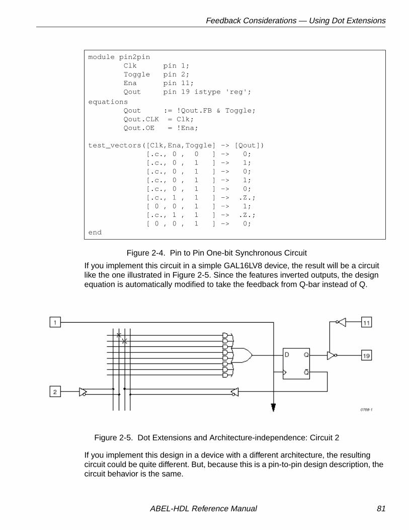
Feedback Considerations — Using Dot Extensions
Figure 2-4. Pin to Pin One-bit Synchronous Circuit
If you implement this circuit in a simple GAL16LV8 device, the result will be a circuitlike the one illustrated in Figure 2-5. Since the features inverted outputs, the designequation is automatically modified to take the feedback from Q-bar instead of Q.
Figure 2-5. Dot Extensions and Architecture-independence: Circuit 2
If you implement this design in a device with a different architecture, the resultingcircuit could be quite different. But, because this is a pin-to-pin design description, thecircuit behavior is the same.
module pin2pin Clk pin 1; Toggle pin 2; Ena pin 11; Qout pin 19 istype 'reg';
equations Qout := !Qout.FB & Toggle; Qout.CLK = Clk; Qout.OE = !Ena;
test_vectors([Clk,Ena,Toggle] -> [Qout]) [.c., 0 , 0 ] -> 0; [.c., 0 , 1 ] -> 1; [.c., 0 , 1 ] -> 0; [.c., 0 , 1 ] -> 1; [.c., 0 , 1 ] -> 0; [.c., 1 , 1 ] -> .Z.; [ 0 , 0 , 1 ] -> 1; [.c., 1 , 1 ] -> .Z.; [ 0 , 0 , 1 ] -> 0;end
ABEL-HDL Reference Manual 81

Feedback Considerations — Using Dot Extensions
Dot Extensions and Detail Design DescriptionsYou may need to be more specific about how you implement a circuit in a targetdevice. More-complex device architectures have many configurable features, and youmay want to use these features in a particular way. You may want a precise powerupand preset operation or, in some cases, you may need to control internal elements.
The circuit previously described (using architecture-independent dot extensions)could be described, for example, using detailed dot extensions in the followingABEL-HDL source file (Figure 2-6):
Figure 2-6. Detail One-bit Synchronous Circuit with Inverted Qout
This version of the design will result in exactly the same fuse pattern as indicated inFigure 2-5. As written, this design assumes the existence of an inverted output for thesignal Qout. This is why the Qout.D and Qout.Q signals are reversed from thearchitecture-independent version of the design presented earlier.
module detail1 Clk pin 1; Toggle pin 2; Ena pin 11; Qout pin 19 istype 'reg_D';
equations !Qout.D = Qout.Q & Toggle;f Qout.CLK = Clk; Qout.OE = !Ena;
test_vectors([Clk,Ena,Toggle] -> [Qout]) [.c., 0 , 0 ] -> 0; [.c., 0 , 1 ] -> 1; [.c., 0 , 1 ] -> 0; [.c., 0 , 1 ] -> 1; [.c., 0 , 1 ] -> 0; [.c., 1 , 1 ] -> .Z.; [ 0 , 0 , 1 ] -> 1; [.c., 1 , 1 ] -> .Z.; [ 0 , 0 , 1 ] -> 0;end
✍ NOTE The inversion operator applied to Qout.D does not corresponddirectly to the inversion found on each output of a GAL16LV8.The equation for Qout.D actually refers to the D input of one ofthe GAL16LV8's flip-flops; the output inversion found in aGAL16LV8 is located after the register and is assumed ratherthan specified.
ABEL-HDL Reference Manual 82

Feedback Considerations — Using Dot Extensions
To implement this design in a device that does not feature inverted outputs, thedesign description must be modified. The following example (Figure 2-7) shows howto write this detailed design for the device that does not feature inverted outputs:
Figure 2-7. Detail One-bit Synchronous Circuit with Non-inverted Qout
module detail2 Clk pin 1; Toggle pin 2; Ena pin 11; Qout pin 19 istype 'reg_D';equations Qout.D = !Qout.Q & Toggle; Qout.CLK = Clk; Qout.OE = !Ena;test_vectors([Clk,Ena,Toggle] -> [Qout]) [.c., 0 , 0 ] -> 0; [.c., 0 , 1 ] -> 1; [.c., 0 , 1 ] -> 0; [.c., 0 , 1 ] -> 1; [.c., 0 , 1 ] -> 0; [.c., 1 , 1 ] -> .Z.; [ 0 , 0 , 1 ] -> 1; [.c., 1 , 1 ] -> .Z.; [ 0 , 0 , 1 ] -> 0;end
ABEL-HDL Reference Manual 83

Using Don't Care Optimization
Using Don't Care OptimizationUse Don't Care optimization to reduce the amount of logic required for anincompletely specified function. The @Dcset directive (used for logic descriptionsections) and Istype attribute 'dc' (used for signals) specify don't care values forunspecified logic.
Consider the following ABEL-HDL truth table:
truth_table ([i3,i2,i1,i0]->[f3,f2,f1,f0]) [ 0, 0, 0, 0]->[ 0, 0, 0, 1]; [ 0, 0, 0, 1]->[ 0, 0, 1, 1]; [ 0, 0, 1, 1]->[ 0, 1, 1, 1]; [ 0, 1, 1, 1]->[ 1, 1, 1, 1]; [ 1, 1, 1, 1]->[ 1, 1, 1, 0]; [ 1, 1, 1, 0]->[ 1, 1, 0, 0]; [ 1, 1, 0, 0]->[ 1, 0, 0, 0]; [ 1, 0, 0, 0]->[ 0, 0, 0, 0];
This truth table has four inputs, and therefore sixteen (24) possible inputcombinations. The function specified, however, only indicates eight significant inputcombinations. For each of the design outputs (f3 through f0) the truth table specifieswhether the resulting value should be 1 or 0. For each output, then, each of the eightindividual truth table entries can be either a member of a set of true functions calledthe on-set, or a set of false functions called the off-set.
Using output f3, for example, the eight input conditions can be listed as on-sets andoff-sets as follows (maintaining the ordering of inputs as specified in the truth tableabove):
on-set of f3 off-set of f3 0 1 1 1 0 0 0 0 1 1 1 1 0 0 0 1 1 1 1 0 0 0 1 1 1 1 0 0 1 0 0 0
The remaining eight input conditions that do not appear in either the on-set or off-setare said to be members of the dc-set, as follows for f3:
dc-set of f3 0 0 1 0 0 1 0 0 0 1 0 1 0 1 1 0 1 0 0 1 1 0 1 0 1 0 1 1 1 1 0 1
ABEL-HDL Reference Manual 84
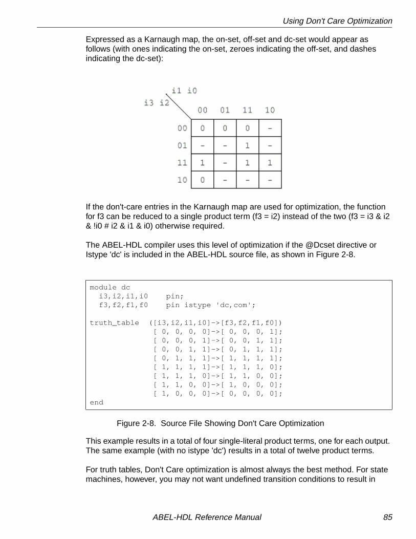
Using Don't Care Optimization
Expressed as a Karnaugh map, the on-set, off-set and dc-set would appear asfollows (with ones indicating the on-set, zeroes indicating the off-set, and dashesindicating the dc-set):
If the don't-care entries in the Karnaugh map are used for optimization, the functionfor f3 can be reduced to a single product term (f3 = i2) instead of the two (f3 = i3 & i2& !i0 # i2 & i1 & i0) otherwise required.
The ABEL-HDL compiler uses this level of optimization if the @Dcset directive orIstype 'dc' is included in the ABEL-HDL source file, as shown in Figure 2-8.
Figure 2-8. Source File Showing Don't Care Optimization
This example results in a total of four single-literal product terms, one for each output.The same example (with no istype 'dc') results in a total of twelve product terms.
For truth tables, Don't Care optimization is almost always the best method. For statemachines, however, you may not want undefined transition conditions to result in
module dc i3,i2,i1,i0 pin; f3,f2,f1,f0 pin istype 'dc,com';
truth_table ([i3,i2,i1,i0]->[f3,f2,f1,f0]) [ 0, 0, 0, 0]->[ 0, 0, 0, 1]; [ 0, 0, 0, 1]->[ 0, 0, 1, 1]; [ 0, 0, 1, 1]->[ 0, 1, 1, 1]; [ 0, 1, 1, 1]->[ 1, 1, 1, 1]; [ 1, 1, 1, 1]->[ 1, 1, 1, 0]; [ 1, 1, 1, 0]->[ 1, 1, 0, 0]; [ 1, 1, 0, 0]->[ 1, 0, 0, 0]; [ 1, 0, 0, 0]->[ 0, 0, 0, 0];end
ABEL-HDL Reference Manual 85

Exclusive OR Equations
unknown states, or you may want to use a default state (determined by the type offlip-flops used for the state register) for state diagram simplification.
When using don't care optimization, be careful not to specify overlapping conditions(specifying both the on-set and dc-set for the same conditions) in your truth tablesand state diagrams. Overlapping conditions result in an error message.
For state diagrams, you can perform additional optimization for design outputs if youspecify the @Dcstate attribute. If you enter @Dcstate in the source file, all statediagram transition conditions are collected during state diagram processing. Thesetransitions are then complemented and applied to the design outputs as don't-cares.You must use @Dcstate in combination with @Dcset or the 'dc' attribute.
Exclusive OR EquationsDesigns written for exclusive-OR (XOR) devices should contain the 'xor' attribute forarchitecture-independence.
Optimizing XOR DevicesYou can use XOR gates directly by writing equations that include XOR operators, oryou can use implied XOR gates. XOR gates can minimize the total number of productterms required for an output or they can emulate alternate flip-flop types.
Using XOR Operators in EquationsIf you want to write design equations that include XOR operators, you must eitherspecify a device that features XOR gates in your ABEL-HDL source file, or specify the'xor' attribute for all output signals that will be implemented with XOR gates. Thispreserves one top-level XOR operator for each design output. For example,
module X1 Q1 pin istype 'com,xor'; a,b,c pin;equations Q1 = a $ b & c;end
Also, when writing equations for XOR PALs, you should use parentheses to groupthose parts of the equation that go on either side of the XOR. This is because theXOR operator ($) and the OR operator (#) have the same priority in ABEL-HDL.
ABEL-HDL Reference Manual 86

Exclusive OR Equations
Using Implied XORs in EquationsHigh-level operators in equations often result in the generation of XOR operators. Ifyou specify the 'XOR' attribute, these implied XORs are preserved, decreasing thenumber of product terms required. For example,
module X2 q3,q2,q1,q0 pin istype 'reg,xor'; clock pin; count = [q3..q0];equations count.clk = clock; count := count.FB + 1;end
This design describes a simple four-bit counter. Since the addition operator results inXOR operators for the four outputs, the 'xor' attribute can reduce the amount ofcircuitry generated.
Using XORs for Flip-flop EmulationAnother way to use XOR gates is for flip-flop emulation. If you are using an XORdevice that has outputs featuring an XOR gate and D-type flip-flops, you can writeyour design as if you were going to be implementing it in a device with T-type flip-flops. The XOR gates and D-type flip-flops emulate the specified T-type flip-flops.When using XORs in this way, you should not use the 'xor' attribute for output signalsunless the target device has XOR gates.
JK Flip-Flop Emulation
You can emulate JK flip-flops using a variety of circuitry found in programmabledevices. When a T-type flip-flop is available, you can emulate JK flip-flops by ANDingthe Q output of the flip-flop with the K input. The !Q output is then ANDed with the Jinput.
✍ NOTE The high-level operator that generates the XOR operatorsmust be the top-level (lowest priority) operation in theequation. An equation such ascount := (count.FB + 1) & !reset ;does not result in the preservation of top-level XOR operators,since the & operator is the top-level operator.
ABEL-HDL Reference Manual 87

Exclusive OR Equations
Figure 2-9 illustrates the circuitry and the Boolean expression.
Figure 2-9. JK Flip-flop Emulation Using T Flip-flop
You can emulate a JK flip-flop with a D flip-flop and an XOR gate. The circuitry andBoolean expression is shown below in Figure 2-10.
Figure 2-10. T Flip-flop Emulation Using D Flip-flop
Finally, you can also emulate a JK flip-flop by combining the D flip-flop emulation of aT flip-flop, in Figure 2-9, with the circuitry of Figure 2-10. Figure 2-11 illustrates thisconcept.
SCT
4
321
Preset
Clear
Clock
T FF
Q
Q
5
6
Q
AND2
12
OR23AND2
3
12
J
K 21
Q : = (J & !Q) # (K & Q)
SC
4
321
Preset
Clear
Clock
FF
Q
Q
5
6
Q
12
3
D
XOR
T
Q : = T $ Q
D
ABEL-HDL Reference Manual 88

Exclusive OR Equations
Figure 2-11. JK Flip-flop Emulation, D Flip-flop with XOR
SC
4
321
Preset
Clear
Clock
FF
Q
Q
5
6
Q
AND2
12
OR23
AND2
3
12
J
K 21
12
XOR
33
D
D
Q : = (Q) $ (J & !Q # K & Q)
ABEL-HDL Reference Manual 89

State Machines
State MachinesA state machine is a digital device that traverses a predetermined sequence of states.State-machines are typically used for sequential control logic. In each state, thecircuit stores its past history and uses that history to determine what to do next.
This section provides some guidelines to help you make state diagrams easy to readand maintain and to help you avoid problems. State machines often have manydifferent states and complex state transitions that contribute to the most commonproblem, which is too many product terms being created for the chosen device. Thetopics discussed in the following subsections help you avoid this problem by reducingthe number of required product terms.
The following subsections provide state machine considerations:
■ Use Identifiers Rather Than Numbers for States
■ Powerup Register States
■ Unsatisfied Transition Conditions, D-type Flip-flops
■ Unsatisfied Transition Conditions, Other Flip-flops
■ Number Adjacent States for a One-bit Change
■ Use State Register Outputs to Identify States
■ Use Symbolic State Descriptions
Use Identifiers Rather Than Numbers for StatesA state machine has different "states" that describe the outputs and transitions of themachine at any given point. Typically, each state is given a name, and the statemachine is described in terms of transitions from one state to another. In a realdevice, such a state machine is implemented with registers that contain enough bitsto assign a unique number to each state. The states are actually bit values in theregister, and these bit values are used along with other signals to determine statetransitions.
As you develop a state diagram, you need to label the various states and statetransitions. If you label the states with identifiers that have been assigned constantvalues, rather than labeling the states directly with numbers, you can easily changethe state transitions or register values associated with each state.
When you write a state diagram, you should first describe the state machine withnames for the states, and then assign state register bit values to the state names.
ABEL-HDL Reference Manual 90

State Machines
For an example, see Figure 2-12, which lists the source file for a state machinenamed "sequence." (This state machine is also discussed in the design examples.)Identifiers (A, B, and C) specify the states. These identifiers are assigned a constantdecimal value in the declaration section that identifies the bit values in the stateregister for each state. A, B, and C are only identifiers: they do not indicate the bitpattern of the state machine. Their declared values define the value of the stateregister (sreg) for each state. The declared values are 0, 1, and 2.
Figure 2-12. Using Identifiers for States
module Sequencetitle 'State machine example';
q1,q0 pin 14,15 istype 'reg'; clock,enab,start,hold,reset pin 1,11,4,2,3; halt pin 17 istype 'reg'; in_B,in_C pin 12,13 istype 'com'; sreg = [q1,q0];
"State Values... A = 0; B = 1; C = 2;
equations [q1,q0,halt].clk = clock; [q1,q0,halt].oe = !enab;
state_diagram sreg; State A: " Hold in state A until start is active. in_B = 0; in_C = 0; IF (start & !reset) THEN B WITH halt := 0; ELSE A WITH halt := halt.fb;
State B: " Advance to state C unless reset is active in_B = 1; " or hold is active. Turn on halt indicator in_C = 0; " if reset. IF (reset) THEN A WITH halt := 1; ELSE IF (hold) THEN B WITH halt := 0; ELSE C WITH halt := 0;
State C: " Go back to A unless hold is active in_B = 0; " Reset overrides hold. in_C = 1; IF (hold & !reset) THEN C WITH halt := 0; ELSE A WITH halt := 0;
ABEL-HDL Reference Manual 91

State Machines
Figure 2-12. Using Identifiers for States (Continued)
Powerup Register StatesIf a state machine has to have a specific starting state, you must define the registerpowerup state in the state diagram description or make sure your design goes to aknown state at powerup. Otherwise, the next state is undefined.
Unsatisfied Transition Conditions
D-type Flip-flops
For each state described in a state diagram, you specify the transitions to the nextstate and the conditions that determine those transitions. For devices with D-typeflip-flops, if none of the stated conditions are met, the state register, shown inFigure 2-13, is cleared to all 0s on the next clock pulse. This action causes the statemachine to go to the state that corresponds to the cleared state register. This caneither cause problems or you can use it to your advantage, depending on yourdesign.
test_vectors([clock,enab,start,reset,hold]->[sreg,halt,in_B,in_C]) [ .p. , 0 , 0 , 0 , 0 ]->[ A , 0 , 0 , 0 ]; [ .c. , 0 , 0 , 0 , 0 ]->[ A , 0 , 0 , 0 ]; [ .c. , 0 , 1 , 0 , 0 ]->[ B , 0 , 1 , 0 ]; [ .c. , 0 , 0 , 0 , 0 ]->[ C , 0 , 0 , 1 ];
[ .c. , 0 , 1 , 0 , 0 ]->[ A , 0 , 0 , 0 ]; [ .c. , 0 , 1 , 0 , 0 ]->[ B , 0 , 1 , 0 ]; [ .c. , 0 , 0 , 1 , 0 ]->[ A , 1 , 0 , 0 ]; [ .c. , 0 , 0 , 0 , 0 ]->[ A , 1 , 0 , 0 ];
[ .c. , 0 , 1 , 0 , 0 ]->[ B , 0 , 1 , 0 ]; [ .c. , 0 , 0 , 0 , 1 ]->[ B , 0 , 1 , 0 ]; [ .c. , 0 , 0 , 0 , 1 ]->[ B , 0 , 1 , 0 ]; [ .c. , 0 , 0 , 0 , 0 ]->[ C , 0 , 0 , 1 ];end
ABEL-HDL Reference Manual 92

State Machines
Figure 2-13. D-type Register with False Inputs
You can use the clearing behavior of D-type flip-flops to eliminate some conditions inyour state diagram and some product terms in the converted design by leaving thecleared-register state transition implicit. If no specified transition condition is met, themachine goes to the cleared-register state. This behavior can also cause problems ifthe cleared-register state is undefined in the state diagram, because if the transitionconditions are not met for any state, the machine goes to an undefined state andstays there.
To avoid problems caused by this clearing behavior, always have a state assigned tothe cleared-register state. Or, if you do not assign a state to the cleared-register state,define every possible condition so some condition is always met for each state. Youcan also use the automatic transition to the cleared-register state by eliminatingproduct terms and explicit definitions of transitions. You can also use the cleared-register state to satisfy illegal conditions.
Other Flip-flops
If none of the state conditions is met in a state machine that employs JK, RS, andT-type flip-flops, the state machine does not advance to the next state, but holds itspresent state due to the low input to the register from the OR array output. In such acase, the state machine can get stuck in a state. You can use this holding behavior toyour advantage in some designs.
If you want to prevent the hold, you can use the complement array provided in somedevices to detect a "no conditions met" situation and reset the state machine to aknown state.
LOGIC0D Q
Q
F0
NO PRODUCT TERM
NO PRODUCT TERM
NO PRODUCT TERM
NO PRODUCT TERM
NO PRODUCT TERM
NO PRODUCT TERM
NO PRODUCT TERM
NO PRODUCT TERM
D-type Register with False Inputs
ABEL-HDL Reference Manual 93

State Machines
Precautions for Using Don't Care OptimizationWhen you use don't care optimization, you need to avoid certain design practices.The most common design technique that conflicts with this optimization is mixingequations and state diagrams to describe default transitions. For example, considerthe design shown in Figure 2-14.
Figure 2-14. State Machines with Conflicting Logic
module TRAFFICtitle 'Traffic Signal Controller' Clk,SenA,SenB pin 1, 8, 7; PR pin 16; "Preset control GA,YA,RA pin 15..13; GB,YB,RB pin 11..9;
"Node numbers are not required if fitter is used S3..S0 node 31..34 istype 'reg_sr,buffer'; COMP node 43;
H,L,Ck,X = 1, 0, .C., .X.; Count = [S3..S0];
"Define Set and Reset inputs to traffic light flip-flops GreenA = [GA.S,GA.R]; YellowA = [YA.S,YA.R]; RedA = [RA.S,RA.R]; GreenB = [GB.S,GB.R]; YellowB = [YB.S,YB.R]; RedB = [RB.S,RB.R]; On = [ 1 , 0 ]; Off = [ 0 , 1 ];
" test_vectors edited
equations [GB,YB,RB].AP = PR; [GA,YA,RA].AP = PR; [GB,YB,RB].CLK = Clk; [GA,YA,RA].CLK = Clk; [S3..S0].AP = PR; [S3..S0].CLK = Clk;
"Use Complement Array to initialize or restart [S3..S0].R = (!COMP & [1,1,1,1]); [GreenA,YellowA,RedA] = (!COMP & [On ,Off,Off]); [GreenB,YellowB,RedB] = (!COMP & [Off,Off,On ]);
ABEL-HDL Reference Manual 94
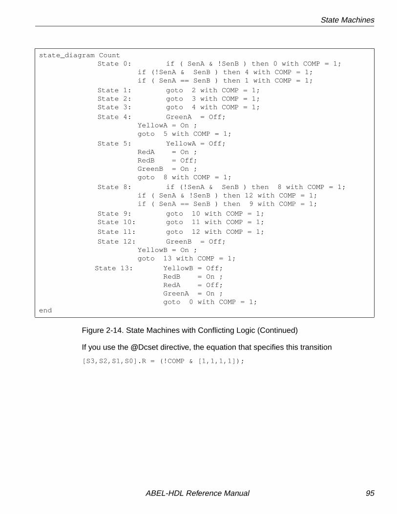
State Machines
Figure 2-14. State Machines with Conflicting Logic (Continued)
If you use the @Dcset directive, the equation that specifies this transition
[S3,S2,S1,S0].R = (!COMP & [1,1,1,1]);
state_diagram CountState 0: if ( SenA & !SenB ) then 0 with COMP = 1;
if (!SenA & SenB ) then 4 with COMP = 1; if ( SenA == SenB ) then 1 with COMP = 1;
State 1: goto 2 with COMP = 1;State 2: goto 3 with COMP = 1;State 3: goto 4 with COMP = 1;
State 4: GreenA = Off; YellowA = On ; goto 5 with COMP = 1;
State 5: YellowA = Off; RedA = On ; RedB = Off; GreenB = On ; goto 8 with COMP = 1;
State 8: if (!SenA & SenB ) then 8 with COMP = 1; if ( SenA & !SenB ) then 12 with COMP = 1; if ( SenA == SenB ) then 9 with COMP = 1;
State 9: goto 10 with COMP = 1;State 10: goto 11 with COMP = 1;
State 11: goto 12 with COMP = 1;
State 12: GreenB = Off; YellowB = On ; goto 13 with COMP = 1;
State 13: YellowB = Off;RedB = On ;RedA = Off;GreenA = On ;goto 0 with COMP = 1;
end
ABEL-HDL Reference Manual 95

State Machines
Figure 2-15 @Dcset-compatible State Machine Description will conflict with the dc-set generated by the state diagram for S3.R , S2.R , S1.R , and S0.R . If equations aredefined for state bits, the @Dcset directive is incompatible. This conflict would resultin an error and failure when the logic for this design is optimized.
To correct the problem, you must remove the @Dcset directive so the implied dc-setequations are folded into the off-set for the resulting logic function. Another option isto rewrite the module as shown in Figure 2-15.
Figure 2-15. @Dcset-compatible State Machine Description
module TRAFFIC1title 'Traffic Signal Controller'
Clk,SenA,SenB pin 1, 8, 7; PR pin 16; "Preset control GA,YA,RA pin 15..13; GB,YB,RB pin 11..9;
S3..S0 node 31..34 istype 'reg_sr,buffer'; H,L,Ck,X = 1, 0, .C., .X.; Count = [S3..S0];
"Define Set and Reset inputs to traffic light flip flops GreenA = [GA.S,GA.R]; YellowA = [YA.S,YA.R]; RedA = [RA.S,RA.R]; GreenB = [GB.S,GB.R]; YellowB = [YB.S,YB.R]; RedB = [RB.S,RB.R]; On = [ 1 , 0 ]; Off = [ 0 , 1 ];
" test_vectors edited
equations [GB,YB,RB].AP = PR; [GA,YA,RA].AP = PR; [GB,YB,RB].CLK = Clk; [GA,YA,RA].CLK = Clk; [S3..S0].AP = PR; [S3..S0].CLK = Clk;
ABEL-HDL Reference Manual 96

State Machines
Figure 2-15. @Dcset-compatible State Machine Description (Continued)
@Dcset state_diagram Count State 0: if ( SenA & !SenB ) then 0; if (!SenA & SenB ) then 4; if ( SenA == SenB ) then 1; State 1: goto 2; State 2: goto 3; State 3: goto 4;
State 4: GreenA = Off; YellowA = On ; goto 5; State 5: YellowA = Off; RedA = On ; RedB = Off; GreenB = On ; goto 8; State 6: goto 0; State 7: goto 0; State 8: if (!SenA & SenB ) then 8; if ( SenA & !SenB ) then 12; if ( SenA == SenB ) then 9; State 9: goto 10; State 10: goto 11; State 11: goto 12; State 12: GreenB = Off; YellowB = On ; goto 13; State 13: YellowB = Off; RedB = On ; RedA = Off; GreenA = On ; goto 0; State 14: goto 0; State 15: "Power up and preset state RedA = Off; YellowA = Off; GreenA = On ; RedB = On ; YellowB = Off; GreenB = Off; goto 0;end
ABEL-HDL Reference Manual 97
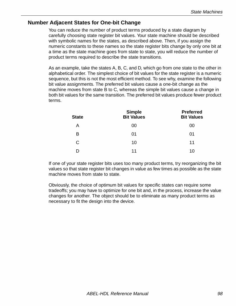
State Machines
Number Adjacent States for One-bit ChangeYou can reduce the number of product terms produced by a state diagram bycarefully choosing state register bit values. Your state machine should be describedwith symbolic names for the states, as described above. Then, if you assign thenumeric constants to these names so the state register bits change by only one bit ata time as the state machine goes from state to state, you will reduce the number ofproduct terms required to describe the state transitions.
As an example, take the states A, B, C, and D, which go from one state to the other inalphabetical order. The simplest choice of bit values for the state register is a numericsequence, but this is not the most efficient method. To see why, examine the followingbit value assignments. The preferred bit values cause a one-bit change as themachine moves from state B to C, whereas the simple bit values cause a change inboth bit values for the same transition. The preferred bit values produce fewer productterms.
If one of your state register bits uses too many product terms, try reorganizing the bitvalues so that state register bit changes in value as few times as possible as the statemachine moves from state to state.
Obviously, the choice of optimum bit values for specific states can require sometradeoffs; you may have to optimize for one bit and, in the process, increase the valuechanges for another. The object should be to eliminate as many product terms asnecessary to fit the design into the device.
StateSimple
Bit ValuesPreferredBit Values
A 00 00
B 01 01
C 10 11
D 11 10
ABEL-HDL Reference Manual 98

State Machines
Use State Register Outputs to Identify StatesSometimes it is necessary to identify specific states of a state machine and signal anoutput that the machine is in one of these states. Fewer equations and outputs areneeded if you organize the state register bit values so one bit in the state registerdetermines if the machine is in a state of interest. Take, for example, the followingsequence of states in which identification of the Cn states is required:
State Register Bit Values
This choice of state register bit values allows you to use Q3 as a flag to indicate whenthe machine is in any of the Cn states. When Q3 is high, the machine is in one of theCn states. Q3 can be assigned directly to an output pin on the device. Notice also thatthese bit values change by only one bit as the machine cycles through the states, asis recommended in the section above.
Using Symbolic State DescriptionsSymbolic state descriptions describe a state machine without having to specify actualstate values Symbolic state descriptions. A symbolic state description is shown inFigure 2-16.
State Name Q3 Q2 Q1
A 0 0 0
B 0 0 1
C1 1 0 1
C2 1 1 1
C3 1 1 0
D 0 1 0
ABEL-HDL Reference Manual 99

State Machines
Figure 2-16. Symbolic State Description
Symbolic state descriptions use the same syntax as non-symbolic state descriptions;the only difference is the addition of the State_register and State declarations, andthe addition of symbolic synchronous and asynchronous reset statements.
module SM a,b,clock pin; " inputs a_reset,s_reset pin; " reset inputs x,y pin istype 'com'; " simple outputs
sreg1 state_register; S0..S3 state;
equations sreg1.clk = clock;
state_diagram sreg1 state S0: goto S1 with {x = a & b; y = 0; } state S1: if (a & b) then S2 with {x = 0; y = 1; } state S2: x = a & b; y = 1; if (a) then S1 else S2; state S3: goto S0 with {x = 1; y = 0; }
async_reset S0: a_reset; sync_reset S0: s_reset;end
ABEL-HDL Reference Manual 100

State Machines
Symbolic Reset Statements
In symbolic state descriptions, the SYNC_RESET and ASYNC_RESET statementsspecify synchronous or asynchronous state machine reset logic. For example, tospecify that a state machine must asynchronously reset to state Start when the Resetinput is true, you write
ASYNC_RESET Start : (Reset) ;
Symbolic Test Vectors
You can also write test vectors to refer to symbolic state values by entering thesymbolic state register name in the test vector header (in the output sections), andthe symbolic state names in the test vectors as output values.
ABEL-HDL Reference Manual 101

Chapter 3 Designing with CPLDs
ABEL-HDL allows you to generate source files with efficient logic for CPLDs,including ispLSI devices.
CPLD Design StrategiesThe following design strategies are helpful when designing for CPLDs. You will findmore detailed information in later sections.
■ Define external and internal signals with PIN and NODE statements, respectively.
■ For state machines and truth tables, include @Dcset (or 'dc' attributes) if possible,since it usually reduces logic.
■ Use only dot extensions that are appropriate for CPLD designs. You can findinformation about using dot extensions in the specific CPLD fitter user manuals.
■ Use intermediate signals to create multi-level logic to match CPLD architectures.
Declaring SignalsThe first step in creating a logic module for a CPLD is to declare the signals in yourdesign. In ABEL-HDL, you do this with PIN and NODE statements.
For example, Figure 3-1 shows a state machine as a functional block. State bits S1through S7 are completely internal; all other signals are external.
Pin PIN statements indicate external signals (used as inputs andoutputs to the functional block). Pin numbers are optional inABEL-HDL and are not recommended for CPLDs, since pinstatements do not actually generate pins on the devicepackage. If you declare an external signal as a node insteadof a pin, the compiler may interpret the signal incorrectly anddelete it.
Node NODE statements indicate internal signals (not accessible bycircuitry outside the functional block). Signals declared asnodes are expected to have a source and loads.
ABEL-HDL Reference Manual 102

CPLD Design Strategies
Figure 3-1. Hypothetical State Machine as a Functional Block
Figure 3-2 shows the corresponding signal declarations. The CLOCK, RESET, input,and output signals must connect with circuitry outside the functional block, so theyare declared as pins. The state bits are not used outside the functional block, so theyare declared as nodes.
Figure 3-2. Signal Declarations
Using Intermediate SignalsAn intermediate signal is a combinatorial signal that is declared as a node and usedas a component of other more complex signals in a design. Intermediate signalsminimize logic by forcing it to be factored. Creating intermediate signals in anABEL-HDL logic description has the following benefits:
■ Reduces the amount of optimization a compiler has to perform
■ Increases the chances of a fit
■ Simplifies the ABEL-HDL source file
Figure 3-4 shows a schematic of combinational logic. Signals A, B, C, D, and E areinputs; X and Y are outputs. There are no intermediate signals; every declared signalis an input or an output to the subcircuit.
CLOCK, RESET Pin;I0,I1,I2,I3 Pin;O1,O2 Pin;
S7,S6,S5,S4,S3,S2,S1 Node;
ABEL-HDL Reference Manual 103
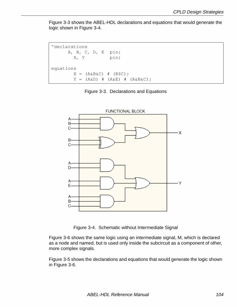
CPLD Design Strategies
Figure 3-3 shows the ABEL-HDL declarations and equations that would generate thelogic shown in Figure 3-4.
Figure 3-3. Declarations and Equations
Figure 3-4. Schematic without Intermediate Signal
Figure 3-6 shows the same logic using an intermediate signal, M, which is declaredas a node and named, but is used only inside the subcircuit as a component of other,more complex signals.
Figure 3-5 shows the declarations and equations that would generate the logic shownin Figure 3-6.
"declarations A, B, C, D, E pin; X, Y pin;
equations X = (A&B&C) # (B$C); Y = (A&D) # (A&E) # (A&B&C);
ABEL-HDL Reference Manual 104

CPLD Design Strategies
Figure 3-5. Declarations and Equations
Figure 3-6. Schematic with Intermediate Signal M
Both design descriptions are functionally the same. Without the intermediate signal,compilation generates the AND gate associated with A&B&C twice, and the devicecompiler must filter out the common term. With the intermediate signal, thissub-signal is generated only once as the intermediate signal, M, and the compiler hasless to do.
Using intermediate signals in a large design, targeted for a complex PLD, can savecompiler optimization effort and time. It also makes the design description easier tointerpret. As another example, compare the state machine descriptions in Figure 3-7and Figure 3-8. Note that Figure 3-8 is easier to read.
"declarations A, B, C, D, E pin; X, Y pin; M node;
equations"intermediate signal equations M = A&B&C; X = M # (B$C); Y = (A&D) # (A&E) # M;
ABEL-HDL Reference Manual 105

CPLD Design Strategies
Figure 3-7. State Machine Description without Intermediate Signals
CASEwhich_code_enter==from_disarmed_ready: CASE (sens_code==sens_off) & (key_code!=key_pound) & (key_code!=key_star) & (key_code!=key_none): code_entry_?X WITH { which_code_enter := which_code_enter; }
(key_code==sens_off) & (key_code==key_none): code_entry_?Y WITH { which_code_enter := which_code_enter; } (key_code==key_pound) # (key_code==key_star): error; (sens_code!=sens_off): error; ENDCASE
which_code_enter==from_armed: CASE (key_code!=key_pound) & (key_code!=key_star) & (key_code!=key_none): code_entry_?X WITH { which_code_enter := which_code_enter; ((key_code==key_pound) # (key_code==key_star)): armed WITH { which_code_enter := which_code_enter; } (key_code==key_none): code_entry_?Y WITH { which_code_enter := which_code_enter; } ENDCASEENDCASE
ABEL-HDL Reference Manual 106

CPLD Design Strategies
Figure 3-8. State Machine Description with Intermediate Signals
CASE
enter_from_disarmed_ready:
CASE
sensors_off & key_numeric: code_entry_?X WITH { which_code_enter := which_code_enter; } sensors_off & key_none: code_entry_?Y WITH { which_code_enter := which_code_enter; } key_pound_star: error;
!sensors_off: error;
ENDCASE
enter_from_armed:
CASE
key_numeric: code_entry_?X WITH { which_code_enter := which_code_enter; }
key_pound_star: armed WITH { which_code_enter := which_code_enter; }
key_none: code_entry_?Y WITH { which_code_enter := which_code_enter; }
ENDCASE
ENDCASE
ABEL-HDL Reference Manual 107

CPLD Design Strategies
The declarations and equations required to create the intermediate signals used inFigure 3-8 are shown in Figure 3-9.
Figure 3-9. Intermediate Signal Declarations and Equations
"pin and node declarations sens_code_0, sens_code_1, sens_code_2, sens_code_3 pin;
key_code_0, key_code_1, key_code_2, key_code_3 pin;
which_code_enter_0, which_code_enter_1, which_code_enter_2 node istype 'reg';
"set declarations which_code_enter = which_code_enter_0..which_code_enter_2]; sens_code = [sens_code_0..sens_code_3]; key_code = [key_code_0 ..key_code_3];
"code-entry sub-states from_disarmed_ready = [1, 0, 0]; from_armed = [0, 0, 0]; sens_off = [0, 0, 0, 0];"key encoding key_pnd = [1, 1, 0, 0]; key_str = [1, 0, 1, 1]; key_non = [0, 0, 0, 0];
"intermediate signals enter_from_disarmed_ready node; enter_from_armed node; sensors_off node; key_numeric node; key_none node; key_pound_star node;
ABEL-HDL Reference Manual 108

CPLD Design Strategies
Figure 3-9. Intermediate Signal Declarations and Equations (Continued)
For large designs, using intermediate signals can be essential. An expression suchas
IF (input==code_1) . . .
generates a product term (AND gate). If the input is 8 bits wide, so is the AND gate. Ifthe expression above is used 10 times, the amount of logic generated will cause longrun times during compilation and fitting, or may cause fitting to fail.
If you write the expression as an intermediate equation,
code_1_found node;
equationscode_1_found = (input==code_1);
you can use the intermediate signal many times without creating an excessiveamount of circuitry.
IF code_1_found . . .
Another way to create intermediate equations is to use the @Carry directive. The@Carry directive causes comparators and adders to be generated using intermediateequations for carry logic. This results in an efficient multilevel implementation.
equations"intermediate equations enter_from_disarmed_ready = (which_code_enter==from_disarmed_ready); enter_from_armed = (which_code_enter==from_armed); sensors_off = (sens_code==sens_off); key_numeric = (key_code!=key_pnd) & (key_code!=key_str) & (key_code!=key_non);
key_none = (key_code==key_non);
key_pound_star = (key_code==key_pnd) # (key_code==key_str);
ABEL-HDL Reference Manual 109

CPLD Design Strategies
Figure 3-10. Typical CPLD Design
ABEL-HDL Reference Manual 110

Chapter 4 Source File Examples
The following examples are representative of programmable logic applications andserve to illustrate significant ABEL-HDL features. You can use these examples to getstarted creating your own source files. For complete information on creating a sourcefile, refer to Chapter 1, “Language Structure” and Chapter 5, “LanguageReference.”
All the examples in this section are installed with your software, and you can usethem without making any changes, or modify them in your designs.
The examples are divided into sections that demonstrate how to use the followingprogrammable logic applications:
■ Equations
■ State Diagrams
■ Truth Tables
■ Combined Logic Descriptions
■ Hierarchy
■ ABEL or ispDesignExpert Projects
ABEL-HDL Reference Manual 111
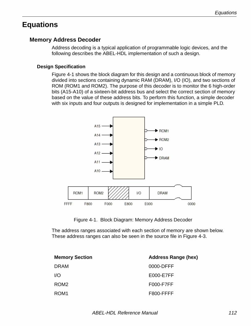
Equations
Equations
Memory Address DecoderAddress decoding is a typical application of programmable logic devices, and thefollowing describes the ABEL-HDL implementation of such a design.
Design Specification
Figure 4-1 shows the block diagram for this design and a continuous block of memorydivided into sections containing dynamic RAM (DRAM), I/O (IO), and two sections ofROM (ROM1 and ROM2). The purpose of this decoder is to monitor the 6 high-orderbits (A15-A10) of a sixteen-bit address bus and select the correct section of memorybased on the value of these address bits. To perform this function, a simple decoderwith six inputs and four outputs is designed for implementation in a simple PLD.
Figure 4-1. Block Diagram: Memory Address Decoder
The address ranges associated with each section of memory are shown below.These address ranges can also be seen in the source file in Figure 4-3.
Memory Section Address Range (hex)
DRAM 0000-DFFF
I/O E000-E7FF
ROM2 F000-F7FF
ROM1 F800-FFFF
ABEL-HDL Reference Manual 112

Equations
Design Method
Figure 4-2 shows a simplified block diagram for the address decoder. The decoder isimplemented with equations employing relational and logical operators as shown inFigure 4-3.
Significant simplification is achieved by grouping the address bits into a set namedAddress. The ten address bits that are not used for the address decode are given no-connect values in the set, indicating that the address in the overall design (thatbeyond the decoder) contains 16 bits, but that bits 0 to 9 do not affect the decode ofthat address and are not monitored. In contrast, defining the set as
Address = [A15,A14,A13,A12,A11,A10]
ignores the existence of the lower-order bits. Specifying all 16 address lines asmembers of the address set allows full 16-bit comparisons of the address valueagainst the ranges shown above.
Figure 4-2. Simplified Block Diagram: Memory Address Decoder
ROM1
ROM2
IO
DRAM
Address
ABEL-HDL Reference Manual 113

Equations
Figure 4-3. Memory Address Decoder Source File
Test Vectors
In this design, the test vectors are a straightforward listing of the values that mustappear on the output lines for specific address values. The address values arespecified in hexadecimal notation.
12-to-4 MultiplexerThe following describes the implementation of a 12-input to 4-output multiplexer usinghigh level equations.
module decodetitle 'memory decode'
A15,A14,A13,A12,A11,A10 pin; ROM1,IO,ROM2,DRAM pin istype 'com'; H,L,X = 1,0,.X.; Address = [A15,A14,A13,A12, A11,A10,X,X, X,X,X,X, X,X,X,X];
equations !DRAM = (Address <= ^hDFFF); !IO = (Address >= ^hE000) & (Address <= ^hE7FF); !ROM2 = (Address >= ^hF000) & (Address <= ^hF7FF); !ROM1 = (Address >= ^hF800);
test_vectors (Address -> [ROM1,ROM2,IO,DRAM]) ^h0000 -> [ H, H, H, L ]; ^h4000 -> [ H, H, H, L ]; ^h8000 -> [ H, H, H, L ]; ^hC000 -> [ H, H, H, L ]; ^hE000 -> [ H, H, L, H ]; ^hE800 -> [ H, H, H, H ]; ^hF000 -> [ H, L, H, H ]; ^hF800 -> [ L, H, H, H ];end
ABEL-HDL Reference Manual 114

Equations
Design Specification
Figure 4-4 shows the block diagram for this design. The multiplexer selects one of thefour inputs and routes that set to the output. The inputs are a0-a3, b0-b3, and c0-c3.The outputs are y0-y3. The routing of inputs to outputs is straightforward: a0 or b0 orc0 is routed to the output y0, a1 or b1 or c1 is routed to the output y1, and so on withthe remaining outputs. The select lines, s0 and s1, control the decoding thatdetermines which set is routed to the output.
Figure 4-4. Block Diagram: 12-to-4 Multiplexer
ABEL-HDL Reference Manual 115

Equations
Design Method
Figure 4-5 shows a block diagram for the same multiplexer after sets have been usedto group the signals. All of the inputs have been grouped into the sets a, b, and c. Theoutputs and select lines are grouped into the sets, y and select, respectively. Thisgrouping of signals into sets takes place in the declaration section of the source filelisted in Figure 4-6.
When the sets have been declared, specification of the design is made with thefollowing four equations that use WHEN-THEN statements.
when (select == 0) then y = a;when (select == 1) then y = b;when (select == 2) then y = c;when (select == 3) then y = c;
The relational expression (==) inside the parentheses produces an expression thatevaluates to true or false value, depending on the values of s0 and s1.
Figure 4-5. Simplified Block Diagram: 12-to-4 Multiplexer
In the first equation, this expression is then ANDed with the set a which contains thefour bits, a0-a3, and could be written as
y = (select == 0) & a
Assume select is equal to 0 (s1 = 0 and s0 = 0), so a true value is produced. The trueis then ANDed with the set a on a bit by bit basis, which in effect sets the product termto a. If select were not equal to 0, the relational expression inside the parentheseswould produce a false value. This value, when ANDed with anything, would give allzeroes.
ABEL-HDL Reference Manual 116

Equations
The other product terms in the equation work in the same manner. Because selecttakes on only one value at a time, only one of the product terms pass the value of aninput set along to the output set. The others contribute 0 bits to the ORs.
Test Vectors
The test vectors for this design are specified in terms of the input, output, and selectsets. Note that the values for a set can be specified by decimal numbers and by othersets. The constants H and L, used in the test vectors, were declared as four bit setscontaining all ones or all zeroes.
Figure 4-6. Source File: 12-to-4 Multiplexer
module Mux12T4title '12 to 4 multiplexer'
a0..a3 pin 1..4; b0..b3 pin 5..8; c0..c3 pin 9, 11, 12, 13; s1,s0 pin 18,19; y0..y3 pin 14..17;
H = [1,1,1,1]; L = [0,0,0,0]; X = .x.; select = [s1, s0]; y = [y3..y0]; a = [a3..a0]; b = [b3..b0]; c = [c3..c0];
equations when (select == 0) then y = a; when (select == 1) then y = b; when (select == 2) then y = c; when (select == 3) then y = c;
test_vectors ([select, a, b, c] -> y) [0 , 1, X, X] -> 1;"select = 0, gates lines a to output [0 ,10, H, L] -> 10; [0 , 5, H, L] -> 5; [1 , H, 3, H] -> 3;"select = 1, gates lines b to output [1 ,10, 7, H] -> 7; [1 , L,15, L] -> 15; [2 , L, L, 8] -> 8;"select = 2, gates lines c to output [2 , H, H, 9] -> 9; [2 , L, L, 1] -> 1; [3 , H, H, 0] -> 0;"select = 3, gates lines c to output [3 , L, L, 9] -> 9; [3 , H, L, 0] -> 0;end
ABEL-HDL Reference Manual 117

Equations
4-Bit Universal CounterThe following design describes the implementation of a 4-bit up/down counter withparallel load and count enable. The design is described using high-level ABEL-HDLequations. Figure 4-7 shows a block diagram of the counter and its signals.Figure 4-8 shows the source file for this design.
Figure 4-7. Block Diagram: 4-bit Universal Counter
The outputs q3, q2, q1, and q0 contain the current count. The least significant bit(LSB) is q0 the most significant bit (MSB) is q3.
Using Sets to Create Modes
The counter has four different modes of operation: Load Data From Inputs, Count Up,Count Down, and Hold Count. You select the modes by applying variouscombinations of values to the inputs cnten , ld , and u_d , as described below. The fourmodes have different priorities, which are defined in the ABEL-HDL description.
The Load mode has the highest priority. If the ld input is high, then the q outputsreflect the value on the d inputs after the next clock edge.
The Hold mode has the next highest priority. Provided ld is low, then when the cnteninput is low, the q outputs maintain their current values upon subsequent clock edges,ignoring any other inputs.
The Up and Down modes have the same priority, and by definition are mutuallyexclusive. Provided cnten is high and ld is low, then when u_d is high, the countercounts up and when u_d is low, the counter counts down.
UNICNTd3
d2
d1
d0
clk
rst
cnten
ld
u_d
q3
q2
q1
q0
I25
ABEL-HDL Reference Manual 118

Equations
Counter Reset
The counter is reset asynchronously by assertion of the input rst .
Using Range Operators
Because this design uses range operators and sets, you can modify the counter to beany width by making changes in the declarations section. You could create a 9-bitcounter by changing the lines which read “d3..d0” and “q3..q0” to “d8..d0” and“q8..q0,” respectively. The range expressions are expanded out and create registersets of corresponding width.
Design Description
Hierarchical Interface Declaration
Directly after the module name, the design contains a hierarchical interfacedeclaration which is used by the ABEL-HDL compiler and linker if another ABEL-HDLsource instantiates this source. The interface list shows all of the input, output, andbidirectional signals (if any) in the design.
Declarations
The declarations contain sections that make the design easier to interpret. Thesections are as follows:
Constants Constant values are defined.
Inputs Design inputs are declared.
Outputs The output pin list contains an Istype declaration forretargetability.
Sets The names data and count are defined as sets (groups)containing the inputs d3, d2, d1, and d0, and the outputs q3,q2, q1, and q0, respectively.
Modes The “Mode equations” are actually more constantdeclarations. First MODE is defined as the set containingcnten , ld , and u_d , in that order. Next, LOAD is defined asbeing true when the members of MODE are equal to X, 1, andX, respectively. HOLD, UP, and DOWN are defined similarly.
ABEL-HDL Reference Manual 119

Equations
Equations
The design of the counter equations enables you to easily define modes and youractual register equations will be easily readable. The counter equation usesWHEN-THEN-ELSE syntax. The first line
when LOAD then count := data
uses the symbolic name LOAD, defined earlier in the source file as
LOAD = (MODE == [X, 1, X])
and MODE itself is a set of inputs in a particular order, defined previously as
MODE = [cnten, ld, u_d]
The first line of the equation could have been written as follows
when ((cnten == X) & (ld == 1) & (u_d == X)) then count := data
which is functionally the same, but the intermediate definitions used instead makesthe source file more readable and easier to modify.
ABEL-HDL Reference Manual 120

Equations
Figure 4-8. Source File: 4-bit Universal Counter
module unicntinterface (d3..d0, clk,rst,ld, u_d -> q3..q0) ;
title '4 bit universal counter with parallel load' ;
"constants X,C,Z = .X., .C., .Z. ;
"inputs d3..d0 pin ; "Data inputs, 4 bits wide clk pin ; "Clock input rst pin ; "Asynchronous reset cnten pin ; "Count enable ld pin ; "Load counter with input data value u_d pin ; "Up/Down selector: HIGH selects up
"outputs q3..q0 pin istype 'reg'; "Counter outputs
"sets data = [d3..d0]; "Data set count = [q3..q0]; "Counter set
"mode equations MODE = [cnten,ld,u_d]; "Mode set composed of control pins. LOAD = (MODE == [ X , 1, X ]);"Various modes are defined by HOLD = (MODE == [ 0 , 0, X ]);"values applied to control pins. UP = (MODE == [ 1 , 0, 1 ]);"Symbolic name may be defined as DOWN = (MODE == [ 1 , 0, 0 ]);"a set equated to a value.
equations when LOAD then count := data "Load counter with data else when UP then count := count + 1 "Count up else when DOWN then count := count - 1 "Count down else when HOLD then count := count ; "Hold count
count.clk = clk; "Counter clock input count.ar = rst; "Counter reset input
"test_vectors edited...
end
✍ NOTE You can also see the advantages of set notation in the testvector section (which has been edited in this manual, but canbe seen in the actual .abl file). In the test vectors, the inputdata is applied as a decimal value, and the output count is adecimal value rather than a set of binary bits.
ABEL-HDL Reference Manual 121

Equations
Bidirectional 3-state BufferA four-bit bidirectional buffer with tri-state outputs is presented here. Simple Booleanequations are used to describe the function.
Design Specification
Figure 4-9 shows a block diagram for this four-bit buffer. Signals A0-A3 and B0-B3function both as inputs and outputs, depending on the value on the select lines, S0-S1. When the select value (the value on the select lines) is 1, A0-A3 are enabled asoutputs. When the select value is 2, B0-B3 are enabled as outputs. (The choice of 1and 2 for select values is arbitrary.) For any other values of the select lines, both theA and B outputs are at high impedance. Output polarity for this design is positive.
Figure 4-9. Block Diagram: Bidirectional 3-state Buffer
ABEL-HDL Reference Manual 122

Equations
Design Method
A simplified block diagram for the buffer is shown in Figure 4-10. The A and Binputs/outputs are grouped into two sets, A and B. The select lines are grouped intothe select set. Figure 4-11 shows the source file that describes the design.
Figure 4-10. Simplified Block Diagram: Bidirectional 3-state Buffer
High-impedance and don't-care values are declared to simplify notation in the sourcefile. The equations section describes the full function of the design. What appear tobe unresolvable equations are written for A and B, with both sets appearing as inputsand outputs. The enable equations, however, enable only one set at a time asoutputs; the other set functions as inputs to the buffer.
Test vectors are written to test the buffer when either set is selected as the output set,and for the case when neither is selected. The test vectors are written in terms of thepreviously declared sets so the element values do not need to be listed separately.
ABEL-HDL Reference Manual 123

Equations
Figure 4-11. Source file: Bidirectional 3-state Buffer
module tsbuffertitle 'bidirectional 3-state buffer' S1,S0 Pin 1,2; Select = [S1,S0]; A3,A2,A1,A0 Pin 12,13,14,15; A = [A3,A2,A1,A0]; B3,B2,B1,B0 Pin 16,17,18,19; B = [B3,B2,B1,B0];
X,Z = .X., .Z.;
equations A = B; B = A;
A.oe = (Select == 1); B.oe = (Select == 2);
test_vectors ([Select, A, B]-> [ A, B]) [ 0 , 0, 0]-> [ Z, Z]; [ 0 , 15, 15]-> [ Z, Z];
[ 1 , X, 5]-> [ 5, X]; [ 1 , X, 10]-> [ 10, X];
[ 2 , 5, X]-> [ X, 5]; [ 2 , 10, X]-> [ X, 10];
[ 3 , 0, 0]-> [ Z, Z]; [ 3 , 15, 15]-> [ Z, Z];end
ABEL-HDL Reference Manual 124

Equations
4-Bit ComparatorThis is a design for a 4-bit comparator that provides an output for “equal to,” “lessthan,” “not equal to,” and “greater than” (as well as intermediate outputs). The designis implemented with high level equations.
Design Specification
The comparator, as shown in Figure 4-12, compares the values of two four-bit inputs(A0-A3 and B0-B3) and determines whether A is equal to, not equal to, less than, orgreater than B. The result of the comparison is shown on the output lines, EQ, GT,NE, and LT.
Figure 4-12. Block Diagram: 4-bit Comparator
Design Method
Figure 4-13 and Figure 4-14 show the simplified block diagram and source file listingfor the comparator. The inputs A0-A3 and B0-B3 are grouped into the sets A and B.YES and NO are defined as 1 and 0, to be used in the test vectors.
The equations section of the source file contains the following equations:
EQ = A == B;NE = !(A == B);GT = A > B;LT = !((A > B) # (A == B));
ABEL-HDL Reference Manual 125
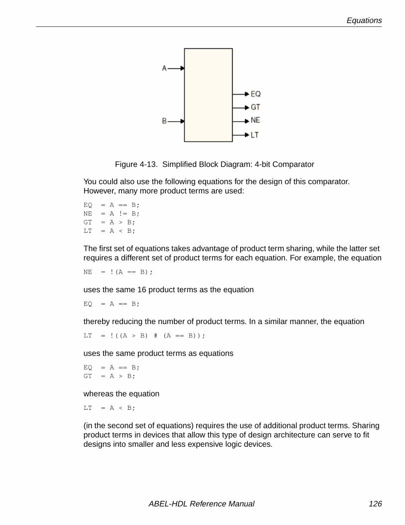
Equations
Figure 4-13. Simplified Block Diagram: 4-bit Comparator
You could also use the following equations for the design of this comparator.However, many more product terms are used:
EQ = A == B;NE = A != B;GT = A > B;LT = A < B;
The first set of equations takes advantage of product term sharing, while the latter setrequires a different set of product terms for each equation. For example, the equation
NE = !(A == B);
uses the same 16 product terms as the equation
EQ = A == B;
thereby reducing the number of product terms. In a similar manner, the equation
LT = !((A > B) # (A == B));
uses the same product terms as equations
EQ = A == B;GT = A > B;
whereas the equation
LT = A < B;
(in the second set of equations) requires the use of additional product terms. Sharingproduct terms in devices that allow this type of design architecture can serve to fitdesigns into smaller and less expensive logic devices.
ABEL-HDL Reference Manual 126

Equations
Figure 4-14. Source File: 4-bit Comparator
Test Vectors
Three separate test vectors sections are written to test three of the four possibleconditions. (The fourth and untested condition of NOT EQUAL TO is simply theinverse of EQUAL TO.) Each test vectors table includes a test vector message thathelps make report output from the compiler and the simulators easier to read.
The three tested conditions are not mutually exclusive, so one or more of them canbe met by a given A and B. In the test vectors table, the constants YES and NO(rather than 1 and 0) are used for ease of reading. YES and NO are declared in thedeclaration section of the source file.
module comp4atitle '4-bit look-ahead comparator'
A3..A0 pin 1..4; A = [A3..A0]; B3..B0 pin 5..8; B = [B3..B0];
NE,EQ,GT,LT pin 16..19 istype 'com';
No,Yes = 0,1;
equations EQ = A == B; NE = !(A == B); GT = A > B; LT = !((A > B) # (A == B));
" test_vectors deleted...
end
ABEL-HDL Reference Manual 127

Truth Table Examples
Truth Table Examples
Seven-segment Display DecoderThis display decoder decodes a four-bit binary number to display the decimalequivalent on a seven-segment LED display. The design incorporates a truth table.
Design Specification
Figure 4-15 shows a block diagram for the design of a seven-segment displaydecoder and a drawing of the display with each of the seven segments labeled tocorrespond to the decoder outputs. To light a segment, the corresponding line mustbe driven low. Four input lines D0-D3 are decoded to drive the correct output lines.The outputs are named a, b, c, d, e, f, and g corresponding to the display segments.All outputs are active low. An enable, ena, is provided. When ena is low, the decoderis enabled; when ena is high, all outputs are driven to high impedance.
Figure 4-15. Block Diagram: Seven-segment Display Decoder
Design Method
Figure 4-16 and Figure 4-17 show the simplified block diagram and the source file forthe ABEL-HDL implementation of the display decoder. The binary inputs and thedecoded outputs are grouped into the sets bcd and led . The constants ON and OFFare declared so the design can be described in terms of turning a segment on or off.To turn a segment on, the appropriate line must be driven low, thus we declare ON as0 and OFF as 1.
ABEL-HDL Reference Manual 128
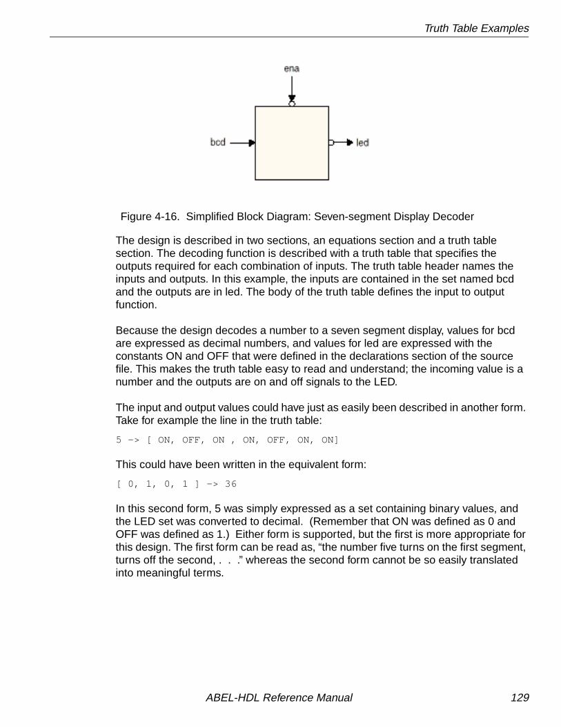
Truth Table Examples
Figure 4-16. Simplified Block Diagram: Seven-segment Display Decoder
The design is described in two sections, an equations section and a truth tablesection. The decoding function is described with a truth table that specifies theoutputs required for each combination of inputs. The truth table header names theinputs and outputs. In this example, the inputs are contained in the set named bcdand the outputs are in led. The body of the truth table defines the input to outputfunction.
Because the design decodes a number to a seven segment display, values for bcdare expressed as decimal numbers, and values for led are expressed with theconstants ON and OFF that were defined in the declarations section of the sourcefile. This makes the truth table easy to read and understand; the incoming value is anumber and the outputs are on and off signals to the LED.
The input and output values could have just as easily been described in another form.Take for example the line in the truth table:
5 -> [ ON, OFF, ON , ON, OFF, ON, ON]
This could have been written in the equivalent form:
[ 0, 1, 0, 1 ] -> 36
In this second form, 5 was simply expressed as a set containing binary values, andthe LED set was converted to decimal. (Remember that ON was defined as 0 andOFF was defined as 1.) Either form is supported, but the first is more appropriate forthis design. The first form can be read as, “the number five turns on the first segment,turns off the second, . . .” whereas the second form cannot be so easily translatedinto meaningful terms.
ABEL-HDL Reference Manual 129

Truth Table Examples
Figure 4-17. Source File: 4-bit Counter with 2-input Mux
Test Vectors
The test vectors for this design test the decoder outputs for the ten valid combinationsof input bits. The enable is also tested by setting ena high for the differentcombinations. All outputs should be at high impedance whenever ena is high.
module bcd7title 'seven segment display decoder'" a" --- BCD-to-seven-segment decoder similar to the 7449" f| g |b" --- segment identification" e| d |c" ---
D3,D2,D1,D0,Ena pin 2,3,4,5,6; a,b,c,d,e,f,g pin 13,14,15,16,17,18,19 istype 'com';
bcd = [D3,D2,D1,D0]; led = [a,b,c,d,e,f,g];
ON,OFF = 0,1; " for common anode LEDs L,H,X,Z = 0,1,.X.,.Z.;
equations led.oe = !Ena;@dcsettruth_table (bcd -> [ a , b , c , d , e , f , g ]) 0 -> [ ON, ON, ON, ON, ON, ON, OFF]; 1 -> [OFF, ON, ON, OFF, OFF, OFF, OFF]; 2 -> [ ON, ON, OFF, ON, ON, OFF, ON]; 3 -> [ ON, ON, ON, ON, OFF, OFF, ON]; 4 -> [OFF, ON, ON, OFF, OFF, ON, ON]; 5 -> [ ON, OFF, ON, ON, OFF, ON, ON]; 6 -> [ ON, OFF, ON, ON, ON, ON, ON]; 7 -> [ ON, ON, ON, OFF, OFF, OFF, OFF]; 8 -> [ ON, ON, ON, ON, ON, ON, ON]; 9 -> [ ON, ON, ON, ON, OFF, ON, ON];" test_vectors editedend
ABEL-HDL Reference Manual 130

State Diagram Examples
State Diagram Examples
3-state SequencerThe following design is a simple sequencer that demonstrates the use of ABEL-HDLstate diagrams. The number of State Diagram states that can be processed dependson the number of transitions and the path of the transitions. For example, a 64-statecounter uses fewer terms (and smaller equations) than a 63-state counter. For largecounter designs, use the syntax CountA:= CountA + 1 to create a counter rather thanusing a state machine. See also example COUNT116.abl for further information oncounter implementation.
Design Specification
Figure 4-18 shows the sequencer design with a state diagram that shows thetransitions and desired outputs. The state machine starts in state A and remains inthat state until the 'start' input becomes high. It then sequences from state A to stateB, from state B to state C, and back to state A. It remains in state A until the 'start'input is high again. If the 'reset' input is high, the state machine returns to state A atthe next clock cycle. If this reset to state A occurs during state B, a 'halt' synchronousoutput goes high, and remains high until the machine is again started.
During states B and C, asynchronous outputs 'in_B' and 'in_C' go high to indicate thecurrent state. Activation of the 'hold' input will cause the machine to hold in state B orC until 'hold' is no longer high, or 'reset' goes high.
Design Method
The sequencer is described by using a STATE_DIAGRAM section in the source file.Figure 4-19 shows the source file for the sequencer. In the source file, the design isgiven a title, the device type is specified, and pin declarations are made. Constantsare declared to simplify the state diagram notation. The two state registers aregrouped into a set called 'sreg' and the three states (A, B, and C) are declared, withappropriate values specified for each.
The state values chosen for this design allow the use of register preload to ensurethat the machine starts in state A. For larger state machines with more state bits,careful numbering of states can dramatically reduce the logic required to implementthe design. Using constant declarations to specify state values saves time when youmake changes to these values.
The state diagram begins with the STATE_DIAGRAM statement that names the set ofsignals to use for the state register. In this example, 'sreg' is the set of signals to use.
ABEL-HDL Reference Manual 131

State Diagram Examples
Figure 4-18. State Diagram: 3-state Sequencer
Within the STATE_DIAGRAM, IF-THEN-ELSE statements are used to indicate thetransitions between states and the input conditions that cause each transition. Inaddition, equations are written in each state that indicate the required outputs foreach state or transition.
For example, state A reads:
State A: in = 0; in_C = 0; if (start & !reset) then B withhalt := 0; else A with halt := halt;
This means that if the machine is in state A, and start is high but reset is low, itadvances to state B. In any other input condition, it remains in state A.
The equations for in_B and in_C indicate those outputs should remain low while themachine is in state A. The equations for halt, specified with the with keyword,indicate that halt should go low if the machine transitions to state B, but shouldremain at its previous value if the machine stays in state A.
ABEL-HDL Reference Manual 132

State Diagram Examples
Test Vectors
The specification of the test vectors for this design is similar to other synchronousdesigns. The first vector is a preload vector, to put the machine into a known state(state A), and the following vectors exercise the functions of the machine. The A, B,and C constants are used in the vectors to indicate the value of the current state,improving the readability of the vectors.
Figure 4-19. Source File: 3-state Sequencer
module sequencetitle 'State machine example';
q1,q0 pin 14,15 istype 'reg,invert'; clock,enab,start,hold,reset pin 1,11,4,2,3; halt pin 17; in_B,in_C pin 12,13; sreg = [q1,q0];
"State Values... A = 0; B = 1; C = 2;
equations [q1,q0,halt].clk = clock; [q1,q0,halt].oe = !enab;
state_diagram sreg; State A: " Hold in state A until start is active. in_B = 0; in_C = 0; IF (start & !reset) THEN B WITH halt := 0; ELSE A WITH halt := halt.fb;
State B: " Advance to state C unless reset is active in_B = 1; " or hold is active. Turn on halt indicator in_C = 0; " if reset. IF (reset) THEN A WITH halt := 1; ELSE IF (hold) THEN B WITH halt := 0; ELSE C WITH halt := 0;
State C: " Go back to A unless hold is active in_B = 0; " Reset overrides hold. in_C = 1; IF (hold & !reset) THEN C WITH halt := 0; ELSE A WITH halt := 0;
" test_vectors edited...end
ABEL-HDL Reference Manual 133

Combined Logic Descriptions
Combined Logic DescriptionsThis section contains an advanced logic design and builds on examples and conceptspresented in the earlier sections of this manual. This design, a blackjack machine, isthe combination of more than one basic logic design. Design specification, methods,and complete source files are given for all parts of the blackjack machine example,which contains the following logic designs:
■ Multiplexer
■ 5-bit adder
■ Binary to BCD converter
■ State machine
This example is a classic blackjack machine based on C.R. Clare's design inDesigning Logic Systems Using State Machines (McGraw Hill, 1972). The blackjackmachine plays the dealer's hand, using typical dealer strategies to decide, after eachround of play, whether to draw another card or to stand.
The blackjack machine consists of these functions: a card reader that reads eachcard as it is drawn, control logic that tells it how to play each hand (based on the totalpoint value of the cards currently held), and display logic that displays scores andstatus on the machine's four LEDs. For this example, we are assuming that the twodigital display devices used to display the score have built-in seven-segmentdecoders.
To operate the machine, insert the dealer's card into the card reader. The machinereads the value and, in the case of later card draws, adds it to the values of previouslyread cards for that hand. (Face cards are valued at 10 points, non-face cards areworth their face value, and aces are counted as either 1 or 11, whichever count yieldsthe best hand.) If the point total is 16 or less, the GT16 line will be asserted (activelow) and the Hit LED will light up. This indicates that the dealer should draw anothercard. If the point total is greater than 16 but less than 22, no LEDs will light up(indicating that the dealer should draw no new cards). If the point total is 22 or higher,LT22 will be asserted (active low) and the Bust LED will light (indicating that thedealer has lost the hand).
The blackjack machine is implemented in three subdesigns:
1. A multiplexer-adder-comparator, which adds the value of the newly drawn card tothe existing hand (and indicates an ace to the state machine);
2. A binary to binary-coded-decimal (BCD) converter, which takes in the five-bitbinary score and converts it to two-digits of BCD for the digital display.
3. The blackjack controller (a state machine that contains the game logic). This logicincludes instructions that determine when to add a card value, when to count anace as 1, and when to count an ace as 11.
ABEL-HDL Reference Manual 134
Combined Logic Descriptions
Circuits that are a straightforward function of a set of inputs and outputs are oftenmost easily expressed in equations; the adder is such a circuit. The subdesignMUXADD for the adder function includes three elements: a multiplexer, the adderitself, and a comparator.
The multiplexer selects either the value of the newly dealt card or one of the two fixedvalues used for the ace (ADD10 or SUB10). The adder adds the value selected bythe multiplexer to the previous score when triggered by the clock signal, ADDCLK.The comparator detects when an ace is present and passes this information on to theblackjack controller, BJACK.
Outputs that do not follow a specific pattern are most easily expressed as truth tables.This is the case with the binary-to-BCD converter that is identified in the schematic asBINBCD. This subdesign converts five bits of binary input to BCD output for twodigital display elements.
The following text describes the internal logic design necessary to keep the cardcount, to control the play sequence, and to show the count on the digital display (orthe state on the Hit and Bust LEDs). Neither the card reader nor the physical designis discussed here. Assume that the card reader provides a binary value that isrepresentative of the card read.
The design has eight inputs (four of which are the binary encoded card values, V0-V3). The remaining four inputs are signals that indicate the following:
■ Restart (the machine is to be restarted)
■ CardIn (a card is in the reader)
■ CardOut (no card is in the reader)
■ CLK (a clock signal to synchronize the design to the card reader)
CardIn, CardOut, and Clk are provided by the card reader. Restart is provided by aswitch on the exterior of the machine.
Module Function in the Blackjack Machine
MUXADD Multiplexer/Adder/Comparator
BINBCD Binary-BCD converter
BJACK State machine
ABEL-HDL Reference Manual 135

Combined Logic Descriptions
Design Specification — MUXADD
MUXADD consists of an input multiplexer, an adder, and a comparator. Themultiplexer determines what value is added to the current score (by the adder). Theadded value consists of the contents of the external card reader (V0-V1 declared asCard), a numeric value of +10, or a numeric value of -10.
The inputs Add10 and Sub10 from the controller (state machine) BJACK determinewhich of the three values the multiplexer selects for application to the adder. Card isapplied to the adder when Add10 and Sub10 are active high, as generated by theBJACK controller. When Add10 becomes active low, 10 is added to the current score(to count an ace as 11 instead of 1), and when Sub10 is active low, -10 is added tothe current score (to count an ace as 1 instead of 11).
The adder provides an output named Score (S0-S4) which is the sum of the currentadder contents and the value selected by the input multiplexer (the card readercontents, +10, or -10). The comparator monitors the contents of the external cardreader (Card) and generates an output, is_Ace, to the BJACK controller that signifiesthat an ace is present in the card reader.
Design Method — MUXADD
MUXADD consists of a three-input multiplexer, a five-bit ripple adder, and a five-bitcomparator. These circuit elements are defined in the equations shown inFigure 4-20. For the multiplexer inputs, a set named Card defines inputs V0 throughV4 as the value of the card reader, while inputs Add10 and Sub10 are used directly inthe following equations to define the multiplexer. The multiplexer output to the adderis named Data and is defined by the equations
Data = Add10 & Sub10 & Card # !Add10 & Sub10 & ten # Add10 & !Sub10 & minus_ten;
The adder (MUXADD) is a five-bit binary ripple adder that adds the current input fromthe multiplexer to the current score, with carry. The adder is clocked by a signal(AddClk) from the BJACK controller and is described with the following equations:
Score := Data $ Score.FB $ CarryIn;CarryOut = Data & Score.FB # (Data # Score.FB) & CarryIn;Reset = !Clr;
In the above equations, Score is the sum of Data (the card reader output, value often, or value of minus ten), Score (the current or last calculated score), and CarryIn(the shifted value of CarryOut, described below). The new value of Score appears atthe S0 through S4 outputs of MUXADD at the time of the AddClk pulse generated bythe BJACK controller (state machine).
ABEL-HDL Reference Manual 136

Combined Logic Descriptions
Before the occurrence of the AddClk clock pulse, an intermediate adder outputappears at combinatorial outputs, labeled C0 through C4 and defined as the setnamed CarryOut (shown below). A second set named CarryIn defines the samecombinatorial outputs as CarryOut, but the outputs are shifted one bit to the left, asshown below.
CarryIn = [C4..C1, 0];CarryOut = [ X,C4..C1];
The set declarations define CarryIn as CarryOut with the required shift to the left forapplication back to adder input. At the time of the AddClk pulse from the BJACKcontroller, CarryIn is added to Score and Data by an exclusive-or operation.
The comparator portion of MUXADD is defined with
is_Ace = Card == 1;
which provides an input to the BJACK controller whenever the value provided by thecard reader is 1.
Test Vectors — MUXADD
The test vectors shown in Figure 4-20 verify operation of MUXADD by first clearingthe adder (so Score is zero), then adding card reader values 7 and 10. The testvectors then input an ace (1) from the card reader (Card) to produce a Score of 1 andpull the is_Ace output high. Subsequent vectors verify the -10 function of the inputmultiplexer and adder. The trace statement lets you observe the carry signals insimulation.
ABEL-HDL Reference Manual 137

Combined Logic Descriptions
Figure 4-20. Source File: Multiplexer/Adder/Comparator
module MuxAddtitle '5-bit ripple adder with input multiplex'
AddClk,Clr,Add10,Sub10,is_Ace pin 1,9,8,7,14; V4..V0 pin; S4..S0 pin; C4..C1 pin;
X,C,L,H = .X., .C., 0, 1;
Card = [V4..V0]; Score = [S4..S0]; CarryIn = [C4..C1, 0]; CarryOut = [ X,C4..C1]; ten = [ 0, 1, 0, 1, 0]; minus_ten = [ 1, 0, 1, 1, 0];
S4..S0 istype 'reg' ;
" Input Multiplexer Data = Add10 & Sub10 & Card # !Add10 & Sub10 & ten # Add10 & !Sub10 & minus_ten;
equations Score := Data $ Score.FB $ CarryIn; CarryOut = Data & Score.FB # (Data # Score.FB) & CarryIn; Score.ar = !(Clr # Clr); Score.clk = AddClk; is_Ace = Card == 1;
" test_vectors edited...end MuxAdd
ABEL-HDL Reference Manual 138

Combined Logic Descriptions
Design Specification — BINBCD
To display the Score, appearing at the output of MUXADD, a binary to bcd converteris implemented. It is the function of the converter to accept the four lines of binarydata generated by MUXADD and provide two sets of binary coded decimal outputsfor two bcd display devices; one to display the units of the current score, and the otherto display the tens. The four-bit output bcd1 (D0-D3) contains the units of the currentscore, and is connected to the high-order display digit. The two-bit output bcd2 (D4and D5) contains the tens, and is fed to the low-order display digit.
BINBCD also provides a pair of outputs to light the Bust and Hit LEDs. Bust is litwhenever Score is 22 or greater; while Hit is lit whenever Score is 16 or less.
Design Method — BINBCD
The design of BINBCD is shown in the source file of Figure 4-21. The design of theconverter is easily expressed with a truth table that lists the value of Score (inputs S0through S4 are declared as Score) for values of bcd1 and bcd2. bcd1 and bcd2 aresets that define the outputs that are fed to the two digital display devices. The truthtable lists Score values up to decimal 31.
The truth table represents a method of expressing the design “manually.” You coulduse a macro to create a truth table in the following manner:
clear(binary);@repeat 32 { binary - [binary/10,binary%10]; inc(binary);}
As indicated in Figure 4-21 (and described in “Test Vectors — BINBCD”), this macrois used to generate the test vectors for the converter. The generated *.lst file showsthe truth table created from the macro.
The BINBCD design also provides the outputs LT22 and GT16 to control the Bust andHit LEDs. A pair of equations generate an active-high LT22 signal to turn off the BustLED when Score is less than 22, and an active-high GT16 signal to turn off the HitLED when Score is greater than 16.
Test Vectors — BINBCD
The test vectors shown in Figure 4-21 verify operation of the LT22 and GT16 outputsof the converter by assigning various values for Score and checking for thecorresponding outputs.
The test vectors for the binary to bcd converter are defined by means of the followingmacro:
test_vectors ( score - [bcd2,bcd1]) clear(binary); @repeat 32 { binary - [binary/10,binary%10]; inc(binary);}
ABEL-HDL Reference Manual 139

Combined Logic Descriptions
This macro generates a test vector with the variable binary set to 0 by the macro (a){@const ?a=0}; (in the binbcd.abl source file shown in Figure 4-21), followed by 31vectors provided by the @repeat directive. The 31 vectors are generated byincrementing the value of the variable binary by a factor of 1 for each vector. Refer tothe inc macro (a) {@const ?a=?a+1;}; line in Figure 4-22. On the output side of thetest vectors, division is used to create the output for bcd2 (tens display digit), whilethe remainder (modulus) operator is used to create the output for bcd1 (units displaydigit).
Figure 4-21. Source File: 4-bit Counter with 2-input Mux
module BINBCDtitle 'comparator and binary to bcd decoder for Blackjack Machine'
" The 5 -bit binary (0 - 31) score is converted into two BCD outputs." The integer division '/' and the modulus operator '%' are used to" extract the individual digits from the two digit score." 'Score % 10' will yield the 'units' and" 'Score / 10' will yield the 'tens'"" The 'GT16' and 'LT22' outputs are for the state machine controller.
S4..S0 pin; score = [S4..S0]; LT22,GT16 pin istype 'com';
D5,D4 pin istype 'com'; bcd2 = [D5,D4]; D3..D0 pin istype 'com'; bcd1 = [D3..D0];
" Digit separation macros binary = 0; "scratch variable clear macro (a) {@const ?a=0}; inc macro (a) {@const ?a=?a+1;};
equations LT22 = (score < 22); "Bust GT16 = (score > 16); "Hit / Stand
" test_vectors edited...truth_table ( score -> [bcd2,bcd1]) 0 -> [ 0 , 0 ]; 1 -> [ 0 , 1 ]; 2 -> [ 0 , 2 ]; 3 -> [ 0 , 3 ]; 4 -> [ 0 , 4 ]; 5 -> [ 0 , 5 ]; 6 -> [ 0 , 6 ]; 7 -> [ 0 , 7 ]; 8 -> [ 0 , 8 ]; 9 -> [ 0 , 9 ];
ABEL-HDL Reference Manual 140

Combined Logic Descriptions
Figure 4-21. Source File: 4-bit Counter with 2-input Mux (Continued)
10 -> [ 1 , 0 ]; 11 -> [ 1 , 1 ]; 12 -> [ 1 , 2 ]; 13 -> [ 1 , 3 ]; 14 -> [ 1 , 4 ]; 15 -> [ 1 , 5 ]; 16 -> [ 1 , 6 ]; 17 -> [ 1 , 7 ]; 18 -> [ 1 , 8 ]; 19 -> [ 1 , 9 ]; 20 -> [ 2 , 0 ]; 21 -> [ 2 , 1 ]; 22 -> [ 2 , 2 ]; 23 -> [ 2 , 3 ]; 24 -> [ 2 , 4 ]; 25 -> [ 2 , 5 ]; 26 -> [ 2 , 6 ]; 27 -> [ 2 , 7 ]; 28 -> [ 2 , 8 ]; 29 -> [ 2 , 9 ]; 30 -> [ 3 , 0 ]; 31 -> [ 3 , 1 ];" This truth table could be replaced with the following macro." clear(binary);" @repeat 32 {" binary -> [binary/10,binary%10]; inc(binary);}"" The test vectors will demonstrate the use of the macro.test_vectors ( score -> [bcd2,bcd1]) clear(binary); @repeat 32 { binary -> [binary/10,binary%10]; inc(binary);}end
ABEL-HDL Reference Manual 141

Combined Logic Descriptions
Design Specification — BJACK
BJACK, the blackjack controller, is technically a state machine (a circuit capable ofstoring an internal state reflecting prior events). State machines use sequential logic,branching to new states and generating outputs on the basis of both the stored statesand external inputs.
In the case of the controller, the state machine stores states that reflect the followingblackjack machine conditions:
■ The value of Score in one of the decimal value ranges (0 to 16, 17 to 21, or 22+).
■ The status of the card reader (card in or card out).
■ The presence of an ace in the card reader.
On the basis of these stored states (and input from each new card), the controllerdecides whether or not a +10 or -10 value is sent to the adder.
Design Method — BJACK
Developing a bubble diagram is the first step in describing a state machine.Figure 4-22 shows a bubble diagram (pictorial state diagram) for the controller. Thisbubble diagram indicates state transitions and the conditions that cause thosetransitions. Transitions are represented by arrows and the conditions causing thetransitions are written alongside the arrow.
You must express the bubble diagram in the form shown in the state_diagram inFigure 4-23. There is a one-to-one correlation between the bubble diagram and thestate diagram described in the source file (Figure 4-23). The table below describesthe state identifiers (state machine states) illustrated in the bubble diagram and listedin the source file.
ABEL-HDL Reference Manual 142

Combined Logic Descriptions
StateIdentifier Description
Clear Clear the state machine, adder, and displays.
ShowHit Indicate that another card is needed. Hit indicator is lit.
AddCard Add the value at the adder input to the current count.
Add10 Add the fixed value 10 to the current count, effectivelygiving an ace a value of 11.
Wt Wait until a card is taken out of the reader.
Test17 Test the current count for a value less than 17.
Test22 Test the current count for a value less than 22.
Sub10 Add the fixed value -10 to the current count, effectivelysubtracting 10 and restoring an ace to 1.
ShowBust Indicate that no more cards are needed. Bust indicatoris lit.
ShowStand Indicate that no more cards are needed. Neither Hit norBust indicators are lit.
ABEL-HDL Reference Manual 143
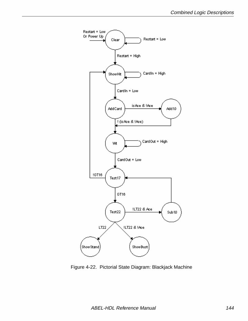
Combined Logic Descriptions
Figure 4-22. Pictorial State Diagram: Blackjack Machine
ABEL-HDL Reference Manual 144

Combined Logic Descriptions
Note that in Figure 4-23, each of the state identifiers (for example, ShowHit) isdefined as sets having binary values. These values were chosen to minimize thenumber of product terms.
Operation of the state machine proceeds as follows if no aces are drawn:
■ If a card is needed from the reader, the state machine goes to state ShowHit.
■ When CardIn goes low, meaning that a card has been read, a transition to stateAddCard is made. The card value is added to the current score.
■ The machine goes to Wait state until the card is withdrawn from the reader.
■ The machine goes to Test17 state.
■ If the score is less than 17, another card is drawn.
■ If the score is greater than or equal to 17, the machine goes to state Test22.
■ If the score is less than 22, the machine goes to the ShowStand state.
■ If the score is 22 or greater, a transition is made to the ShowBust state.
■ In either ShowStand or ShowBust state, a transition is made to Clear (to clear thestate register and adder) when Restart goes low.
■ When Restart goes back to high, the state machine returns to ShowHit and thecycle begins again.
Operation of the state machine when an ace is drawn is essentially the same. A cardis drawn and the score is added. If the card is an ace and no ace has been drawnpreviously, the state machine goes to state Add10, and ten is added to the count (ineffect making the ace an 11). Transitions to and from Test17 and Test22 proceed asbefore. However, if the score exceeds 21 and an ace has been set to 11, the statemachine goes to state Sub10, 10 is subtracted from the score, and the state machinegoes to state Test17.
Test Vectors — BJACK
Figure 4-23 shows three sets of test vectors; each set represents a different “hand” ofplay (as described above the set of vectors) and tests the different functions of thedesign. The Restart function is used to set the design to a known state between eachhand, and the state identifiers are used instead of the binary values (which theyrepresent).
ABEL-HDL Reference Manual 145

Combined Logic Descriptions
Figure 4-23. Source File: State Machine (Controller)
module bjacktitle 'BlackJack state machine controller'
"Inputs Clk,ClkIN pin; "System clock GT16,LT22 pin; "Score less than 17 and 22 is_Ace pin; "Card is ace Restart pin; "Restart game CardIn,CardOut pin; "Card present switches Ena pin;
Sensor = [CardIn,CardOut]; _In = [ 0 , 1 ]; InOut = [ 1 , 1 ]; Out = [ 1 , 0 ];
"Outputs AddClk pin istype 'com'; "Adder clock Add10 pin istype 'reg_D,invert'; "Input Mux control Sub10 pin istype 'reg_D,invert'; "Input Mux control Q2,Q1,Q0 pin istype 'reg_D,invert'; Ace pin istype 'reg_D,invert'; "Ace Memory
High,Low = 1,0; H,L,C,X = 1,0,.C.,.X.; "test vector characters
Qstate = [Add10,Sub10,Q2,Q1,Q0]; Clear = [ 1 , 1 , 1, 1, 1]; "31 ShowHit = [ 1 , 1 , 1, 1, 0]; "30 AddCard = [ 1 , 1 , 0, 0, 0]; "24 Add_10 = [ 0 , 1 , 0, 0, 0]; "16 Wt = [ 1 , 1 , 0, 0, 1]; "25 Test_17 = [ 1 , 1 , 0, 1, 0]; "26 Test_22 = [ 1 , 1 , 0, 1, 1]; "27 ShowStand = [ 1 , 1 , 1, 0, 0]; "28 ShowBust = [ 1 , 1 , 1, 0, 1]; "29 Sub_10 = [ 1 , 0 , 0, 0, 1]; "17 Zero = [ 0 , 0 , 0, 0, 0]; "0equations [Qstate,Ace].c = Clk; [Qstate,Ace].oe = !Ena;
@dcsetstate_diagram Qstate
State Clear: AddClk = !ClkIN; Ace := Low; if (Restart==Low) then Clear else ShowHit;
State ShowHit: AddClk = Low; Ace := Ace; if (CardIn==Low) then AddCard else ShowHit;
ABEL-HDL Reference Manual 146
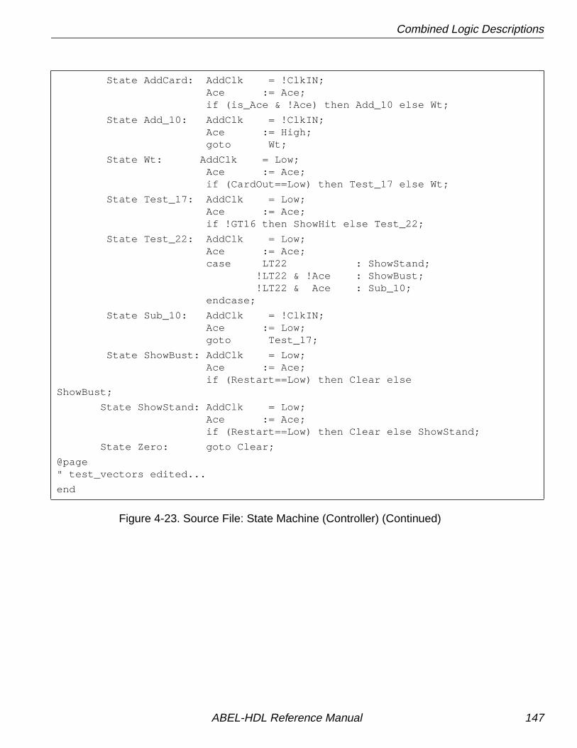
Combined Logic Descriptions
Figure 4-23. Source File: State Machine (Controller) (Continued)
State AddCard: AddClk = !ClkIN; Ace := Ace; if (is_Ace & !Ace) then Add_10 else Wt;
State Add_10: AddClk = !ClkIN; Ace := High; goto Wt;
State Wt: AddClk = Low; Ace := Ace; if (CardOut==Low) then Test_17 else Wt;
State Test_17: AddClk = Low; Ace := Ace; if !GT16 then ShowHit else Test_22;
State Test_22: AddClk = Low; Ace := Ace; case LT22 : ShowStand; !LT22 & !Ace : ShowBust; !LT22 & Ace : Sub_10; endcase;
State Sub_10: AddClk = !ClkIN; Ace := Low; goto Test_17;
State ShowBust: AddClk = Low; Ace := Ace; if (Restart==Low) then Clear elseShowBust;
State ShowStand: AddClk = Low; Ace := Ace; if (Restart==Low) then Clear else ShowStand;
State Zero: goto Clear;
@page" test_vectors edited...
end
ABEL-HDL Reference Manual 147

Hierarchy Examples
Hierarchy ExamplesThe following ABEL-HDL source files show how to combine the three blackjackexamples into one top-level source for implementation in a larger device.
The three lower-level modules are unchanged from the non-hierarchical versions.
The test vectors have been removed.
module bjacktop;title 'instantiating bjack, muxadd, binbcd'
// Sub-module prototypes... bjack interface(Clk,ClkIN,GT16,LT22,is_Ace,Restart,CardIn,CardOut,Ena :> AddClk, Add10,Sub10,Q2..Q0, Ace);
muxadd interface (V0..V4,AddClk,Clr,Add10,Sub10 :> S0..S4 -> is_Ace);
binbcd interface (S0..S4 -> LT22, GT16, D0..D5);
// Sub-module instantiations... BJ functional_block bjack; MA functional_block muxadd; BB functional_block binbcd;
// Top level inputs... Clk pin; "System clock -- bjack CardIn,CardOut pin; "Card present switches -- bjack Restart pin; "Restart game -- bjack V4..V0 pin; " -- muxadd Ace pin; Card = [V4..V0]; Sensor = [CardIn,CardOut]; _In = [ 0 , 1 ]; InOut = [ 1 , 1 ]; Out = [ 1 , 0 ];
// Top level outputs...
D5..D0 pin istype 'com'; " -- binbcd BCD1 = [D3..D0]; BCD2 = [D5,D4];
ABEL-HDL Reference Manual 148

Hierarchy Examples
// Top level pins (for observing state machine)... Q2..Q0 pin istype 'com'; Add10,Sub10 pin istype 'com'; AddClk node istype 'com,keep';
Qstate = [Add10,Sub10,Q2,Q1,Q0]; Clear = [ 1 , 1 , 1, 1, 1]; "31 ShowHit = [ 1 , 1 , 1, 1, 0]; "30 AddCard = [ 1 , 1 , 0, 0, 0]; "24 Add_10 = [ 0 , 1 , 0, 0, 0]; "16 Wt = [ 1 , 1 , 0, 0, 1]; "25 Test_17 = [ 1 , 1 , 0, 1, 0]; "26 Test_22 = [ 1 , 1 , 0, 1, 1]; "27 ShowStand = [ 1 , 1 , 1, 0, 0]; "28 ShowBust = [ 1 , 1 , 1, 0, 1]; "29 Sub_10 = [ 1 , 0 , 0, 0, 1]; "17 Zero = [ 0 , 0 , 0, 0, 0]; "0
Hit = !BB.GT16; Bust = !BB.LT22;
C,X,L,H = .c.,.x.,0,1;
equations
// Describe the input connections... MA.[V4,V3,V2,V1,V0] = Card; MA.Clr = Restart; BJ.Clk = Clk; BJ.ClkIN = Clk; BJ.Restart = Restart; BJ.CardIn = CardIn; BJ.CardOut = CardOut; BJ.Ena = 0;
// Describe the output connections... [D5,D4,D3,D2,D1,D0] = BB.[D5,D4,D3,D2,D1,D0]; Add10 = BJ.Add10; Sub10 = BJ.Sub10; Q0 = BJ.Q0; Q1 = BJ.Q1; Q2 = BJ.Q2; Ace = BJ.Ace;
// Describe inter-module connections... MA.Sub10 = BJ.Sub10; MA.Add10 = BJ.Add10; AddClk = BJ.AddClk; MA.AddClk = AddClk; BB.[S0,S1,S2,S3,S4] = MA.[S0,S1,S2,S3,S4]; BJ.is_Ace = MA.is_Ace; BJ.GT16 = BB.GT16; BJ.LT22 = BB.LT22;
end;
ABEL-HDL Reference Manual 149
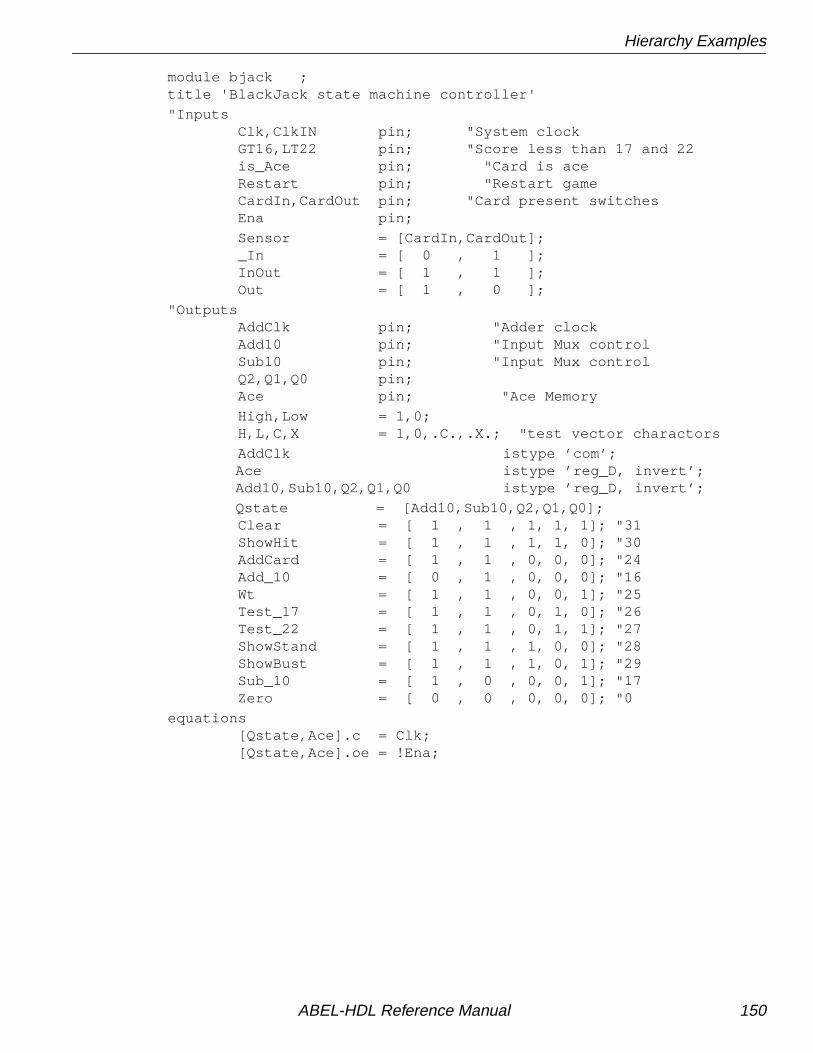
Hierarchy Examples
module bjack ;title 'BlackJack state machine controller'
"Inputs Clk,ClkIN pin; "System clock GT16,LT22 pin; "Score less than 17 and 22 is_Ace pin; "Card is ace Restart pin; "Restart game CardIn,CardOut pin; "Card present switches Ena pin;
Sensor = [CardIn,CardOut]; _In = [ 0 , 1 ]; InOut = [ 1 , 1 ]; Out = [ 1 , 0 ];
"Outputs AddClk pin; "Adder clock Add10 pin; "Input Mux control Sub10 pin; "Input Mux control Q2,Q1,Q0 pin; Ace pin; "Ace Memory
High,Low = 1,0; H,L,C,X = 1,0,.C.,.X.; "test vector charactors
AddClk istype ’com’; Ace istype ’reg_D, invert’; Add10,Sub10,Q2,Q1,Q0 istype ’reg_D, invert’;
Qstate = [Add10,Sub10,Q2,Q1,Q0]; Clear = [ 1 , 1 , 1, 1, 1]; "31 ShowHit = [ 1 , 1 , 1, 1, 0]; "30 AddCard = [ 1 , 1 , 0, 0, 0]; "24 Add_10 = [ 0 , 1 , 0, 0, 0]; "16 Wt = [ 1 , 1 , 0, 0, 1]; "25 Test_17 = [ 1 , 1 , 0, 1, 0]; "26 Test_22 = [ 1 , 1 , 0, 1, 1]; "27 ShowStand = [ 1 , 1 , 1, 0, 0]; "28 ShowBust = [ 1 , 1 , 1, 0, 1]; "29 Sub_10 = [ 1 , 0 , 0, 0, 1]; "17 Zero = [ 0 , 0 , 0, 0, 0]; "0
equations [Qstate,Ace].c = Clk; [Qstate,Ace].oe = !Ena;
ABEL-HDL Reference Manual 150

Hierarchy Examples
@dcsetstate_diagram Qstate
State Clear: AddClk = !ClkIN; Ace := Low; if (Restart==Low) then Clear else ShowHit;
State ShowHit: AddClk = Low; Ace := Ace; if (CardIn==Low) then AddCard else ShowHit;
State AddCard: AddClk = !ClkIN; Ace := Ace; if (is_Ace & !Ace) then Add_10 else Wt;
State Add_10: AddClk = !ClkIN; Ace := High; goto Wt;
State Wt: AddClk = Low; Ace := Ace; if (CardOut==Low) then Test_17 else Wt;
State Test_17: AddClk = Low; Ace := Ace; if !GT16 then ShowHit else Test_22;
State Test_22: AddClk = Low; Ace := Ace; case LT22 : ShowStand; !LT22 & !Ace : ShowBust; !LT22 & Ace : Sub_10; endcase;
State Sub_10: AddClk = !ClkIN; Ace := Low; goto Test_17;
State ShowBust: AddClk = Low; Ace := Ace; if (Restart==Low) then Clear else ShowBust;
State ShowStand: AddClk = Low; Ace := Ace; if (Restart==Low) then Clear else ShowStand;
State Zero: goto Clear;
end
ABEL-HDL Reference Manual 151

Hierarchy Examples
module muxadd ;title '5-bit ripple adder with input multiplex'
AddClk,Clr,Add10,Sub10,is_Ace pin; V4,V3,V2,V1,V0 pin; S4,S3,S2,S1,S0 pin; C4,C3,C2,C1 pin;
X,C,L,H = .X., .C., 0, 1;
Card = [V4,V3,V2,V1,V0]; Score = [S4,S3,S2,S1,S0]; CarryIn = [C4,C3,C2,C1, 0]; CarryOut = [ X,C4,C3,C2,C1]; ten = [ 0, 1, 0, 1, 0]; minus_ten = [ 1, 0, 1, 1, 0];
S4,S3,S2,S1,S0 istype 'reg' ;
" Input Multiplexer Data = Add10 & Sub10 & Card # !Add10 & Sub10 & ten # Add10 & !Sub10 & minus_ten;
equations Score := Data $ Score $ CarryIn;
CarryOut = Data & Score # (Data # Score) & CarryIn;
Score.ar = !Clr;
Score.c = AddClk;
is_Ace = Card == 1;
end;
module binbcd;title 'comparator and binary to bcd decoder for Blackjack Machine'
" The 5 -bit binary (0 - 31) score is converted into two BCD outputs." The interger division '/' and the modulus operator '%' are used to" extract the individual digits from the two digit score." 'Score % 10' will yield the 'units' and" 'Score / 10' will yield the 'tens'"" The 'GT16' and 'LT22' outputs are for the state machine controller.
S4,S3,S2,S1,S0 pin; score = [S4,S3,S2,S1,S0];
LT22,GT16 pin istype 'com';
D5,D4 pin istype 'com'; bcd2 = [D5,D4];
D3,D2,D1,D0 pin istype 'com'; bcd1 = [D3,D2,D1,D0];
" Digit separation macros binary = 0; "scratch variable clear macro (a) {@const ?a=0}; inc macro (a) {@const ?a=?a+1;};
ABEL-HDL Reference Manual 152

Hierarchy Examples
equations LT22 = (score < 22); "Bust GT16 = (score > 16); "Hit / Stand
test_vectors ( score -> [GT16,LT22]) 1 -> [ 0 , 1 ]; 6 -> [ 0 , 1 ]; 8 -> [ 0 , 1 ]; 16 -> [ 0 , 1 ]; 17 -> [ 1 , 1 ]; 18 -> [ 1 , 1 ]; 20 -> [ 1 , 1 ]; 21 -> [ 1 , 1 ]; 22 -> [ 1 , 0 ]; 23 -> [ 1 , 0 ]; 24 -> [ 1 , 0 ];
truth_table ( score -> [bcd2,bcd1]) 0 -> [ 0 , 0 ]; 1 -> [ 0 , 1 ]; 2 -> [ 0 , 2 ]; 3 -> [ 0 , 3 ]; 4 -> [ 0 , 4 ]; 5 -> [ 0 , 5 ]; 6 -> [ 0 , 6 ]; 7 -> [ 0 , 7 ]; 8 -> [ 0 , 8 ]; 9 -> [ 0 , 9 ]; 10 -> [ 1 , 0 ]; 11 -> [ 1 , 1 ]; 12 -> [ 1 , 2 ]; 13 -> [ 1 , 3 ]; 14 -> [ 1 , 4 ]; 15 -> [ 1 , 5 ]; 16 -> [ 1 , 6 ]; 17 -> [ 1 , 7 ]; 18 -> [ 1 , 8 ]; 19 -> [ 1 , 9 ]; 20 -> [ 2 , 0 ]; 21 -> [ 2 , 1 ]; 22 -> [ 2 , 2 ]; 23 -> [ 2 , 3 ]; 24 -> [ 2 , 4 ]; 25 -> [ 2 , 5 ]; 26 -> [ 2 , 6 ]; 27 -> [ 2 , 7 ]; 28 -> [ 2 , 8 ]; 29 -> [ 2 , 9 ]; 30 -> [ 3 , 0 ]; 31 -> [ 3 , 1 ];
ABEL-HDL Reference Manual 153

Hierarchy Examples
" This truth table could be replaced with the following macro." clear(binary);" @repeat 32 {" binary -> [binary/10,binary%10]; inc(binary);}""" The test vectors will demonstrate the use of the macro."test_vectors ( score -> [bcd2,bcd1]) clear(binary); @repeat 32 { binary -> [binary/10,binary%10]; inc(binary);}end
ABEL-HDL Reference Manual 154

ABEL and ispDesignExpert Projects
ABEL and ispDesignExpert ProjectsThe following ABEL-HDL source, p6top .abl , (Figure 4-24) instantiates variableinstances of prep6 .abl (Figure 4-25).
Figure 4-24. Top-level ABEL-HDL Source
module p6top (rep)title 'Variable instances of PREP6'
@ifb (?rep) { @message 'Must specify -arg N' @exit } D15..D0 pin; Q15..Q0 pin istype 'reg'; Clk, Rst pin;
Q = [Q15..Q0]; D = [D15..D0];
@const N = ?rep - 1;
prep6 interface (D15..D0, Clk, Rst -> Q15..Q0);
ACC macro (i) { @expr {ACC}?i; }
@const i = 0; @repeat ?rep { ACC(i) functional_block prep6; @const i = i + 1; }
equations ACC0.[D15..D0] = D;
@const i = 0; @repeat ?rep { ACC(i).[Clk, Rst] = [Clk, Rst]; @const i = i+1; }
@const i = 0; @repeat ?rep-1 { ACC(i+1).[D15..D0] = ACC(i).[Q15..Q0]; @const i = i+1; } Q = ACC(N).[Q15..Q0];end
ABEL-HDL Reference Manual 155

ABEL and ispDesignExpert Projects
Lower-level SourcesFigure 4-25 shows the lower-level ABEL-HDL file instantiated by p6top .abl . This filedoes not contain an interface statement, which is optional in lower-level files.
Figure 4-25. Lower-level ABEL-HDL Source
module prep6
title ‘16-Bit Accumulator’
D15..D0 pin;Q15..Q0 pin istype ‘reg’;Clk, Rst pin;
Q = [Q15..Q0];D = [D15..D0];
@carry 2;equations Q := D + Q; Q.C = Clk; Q.AR = Rst;end
ABEL-HDL Reference Manual 156

Chapter 5 Language Reference
This chapter provides detailed information about each of the language elements inABEL-HDL. It assumes you are familiar with the basic syntax discussed in Chapter 1,“Language Structure.” Each entry contains the following sections (if applicable):
■ Syntax — is the required syntax for the element.
■ Purpose — is a brief description of the intended use of the element.
■ Use — is a discussion of the potential uses of the element, including any specialconsiderations.
■ Examples — are examples of the element as it is used in a design description.
■ See Also — refers to other elements and discussions, and to design examplesthat demonstrate the use of an element.
Basic syntax information (on subjects such as blocks, strings, sets and arguments) isprovided in Chapter 1, “Language Structure.”
ABEL-HDL Reference Manual 157

. ext — Dot Extensions
. ext — Dot ExtensionsSyntax
signal_name. ext
Purpose
Dot extensions provide a way to refer specifically to internal signals and nodesthat are associated with a primary signal in your design.
Use
Signal dot extensions describe, more precisely, the behavior of signals in alogic description, and remove the ambiguities in equations.
You can use ABEL-HDL dot extensions in complex language constructs, suchas nested sets or complex expressions.
Using Pin-to-Pin Vs. Detailed Dot Extensions
Dot extensions allow you to refer to various circuit elements (such as registerclocks, presets, feedback and output enables) that are related to a primarysignal.
Some dot extensions are general purpose and are intended for use with awide variety of device architectures. These dot extensions are thereforereferred to as pin-to-pin (or “architecture-independent”). Other dot extensionsare intended for specific classes of device architectures, or require specificdevice configurations. These dot extensions are referred to as detailed (or“architecture-dependent” or “device-specific”) dot extensions.
In most cases, you can describe a circuit using either pin-to-pin or detailed dotextensions. Which form you use depends on the application and whether youwant to implement the application in a variety of architectures. Theadvantages of each method are discussed later in this section.
Table 5-1 lists the ABEL-HDL dot extensions. Pin-to-pin dot extensions areindicated with a check in the Pin-to-Pin column.
ABEL-HDL Reference Manual 158
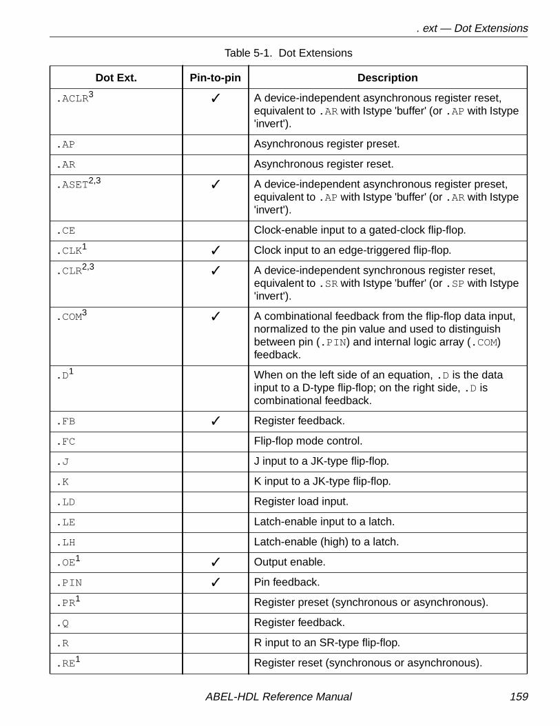
. ext — Dot Extensions
Table 5-1. Dot Extensions
Dot Ext. Pin-to-pin Description
.ACLR3 ✓ A device-independent asynchronous register reset,equivalent to .AR with Istype 'buffer' (or .AP with Istype'invert').
.AP Asynchronous register preset.
.AR Asynchronous register reset.
.ASET2,3 ✓ A device-independent asynchronous register preset,equivalent to .AP with Istype 'buffer' (or .AR with Istype'invert').
.CE Clock-enable input to a gated-clock flip-flop.
.CLK 1 ✓ Clock input to an edge-triggered flip-flop.
.CLR2,3 ✓ A device-independent synchronous register reset,equivalent to .SR with Istype 'buffer' (or .SP with Istype'invert').
.COM3 ✓ A combinational feedback from the flip-flop data input,normalized to the pin value and used to distinguishbetween pin (.PIN ) and internal logic array (.COM)feedback.
.D 1 When on the left side of an equation, .D is the datainput to a D-type flip-flop; on the right side, .D iscombinational feedback.
.FB ✓ Register feedback.
.FC Flip-flop mode control.
.J J input to a JK-type flip-flop.
.K K input to a JK-type flip-flop.
.LD Register load input.
.LE Latch-enable input to a latch.
.LH Latch-enable (high) to a latch.
.OE1 ✓ Output enable.
.PIN ✓ Pin feedback.
.PR 1 Register preset (synchronous or asynchronous).
.Q Register feedback.
.R R input to an SR-type flip-flop.
.RE 1 Register reset (synchronous or asynchronous).
ABEL-HDL Reference Manual 159
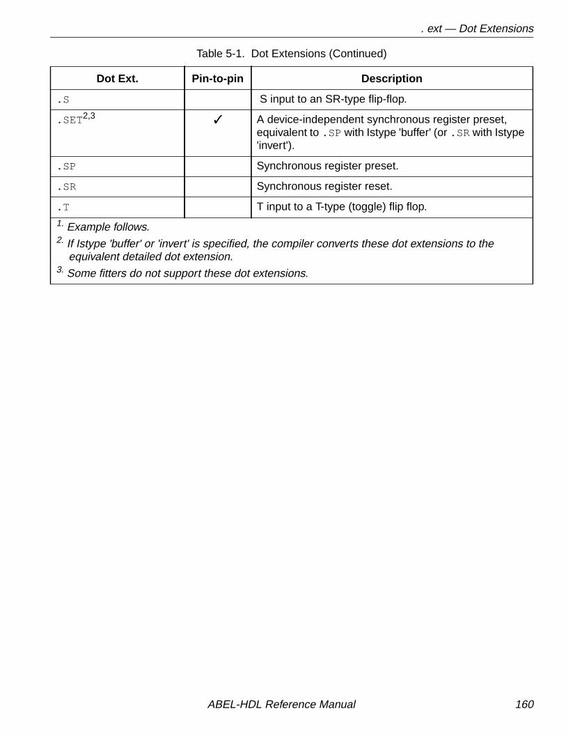
. ext — Dot Extensions
.S S input to an SR-type flip-flop.
.SET 2,3 ✓ A device-independent synchronous register preset,equivalent to .SP with Istype 'buffer' (or .SR with Istype'invert').
.SP Synchronous register preset.
.SR Synchronous register reset.
.T T input to a T-type (toggle) flip flop.1. Example follows.2. If Istype 'buffer' or 'invert' is specified, the compiler converts these dot extensions to the equivalent detailed dot extension.3. Some fitters do not support these dot extensions.
Table 5-1. Dot Extensions (Continued)
Dot Ext. Pin-to-pin Description
ABEL-HDL Reference Manual 160

. ext — Dot Extensions
Detailed Design Dot Extensions
Table 5-2 shows the dot extensions that are supported (and which of those arerequired) for different register types in detailed design descriptions. The required dotextensions are indicated with a check in the Extension Required column.
Table 5-2. Dot Extensions for Device-specific (detailed) Designs
Register TypeExtensionRequired
SupportedExtensions Definition
combinational (no register) .oe.pin.com
output enablepin feedbackcombinational feedback
D-type flip-flop ✓✓
.clk
.d
.fc
.oe
.q
.sp
.sr
.ap
.ar
.pin
clockdata inputflip-flop mode controloutput enableflip-flop feedbacksynchronous presetsynchronous resetasynchronous presetasynchronous resetpin
JK-type flip-flop ✓✓✓
.clk
.j
.k
.fc
.oe
.q
.sp
.sr
.ap
.ar
.pin
clockj inputk inputflip-flop mode controloutput enableflip-flop feedbacksynchronous resetsynchronous resetasynchronous presetasynchronous resetpin feedback
SR-type flip-flop ✓✓✓
.clk
.s
.r
.oe
.q
.sp
.sr
.ap
.ar
.pin
clockset inputreset inputoutput enableflip-flop feedbacksynchronous presetsynchronous resetasynchronous presetasynchronous presetpin feedback
ABEL-HDL Reference Manual 161

. ext — Dot Extensions
T-type flip-flop ✓✓
.clk
.t
.oe
.q
.sp
.sr
.ap
.ar
.pin
clocktoggle inputoutput enableflip-flop feedbacksynchronous presetsynchronous resetasynchronous presetasynchronous resetpin feedback
L-type latch ✓✓
.d
.le
.lh
.oe
.q
.pin
data inputlatch enable input to a latchlatch enable (high) input toa latchoutput enableflip-flop feedbackpin feedback
Gated clock D flip-flop ✓✓
.clk or .ce
.d
.oe
.q
.pin
clock or clock enabledata inputoutput enableflip-flop feedbackpin feedback
Table 5-2. Dot Extensions for Device-specific (detailed) Designs (Continued)
Register TypeExtensionRequired
SupportedExtensions Definition
ABEL-HDL Reference Manual 162

. ext — Dot Extensions
Pin-to-Pin Design Dot Extensions
Table 5-3 shows the dot extensions that are allowable (and which of those arerequired) for pin-to-pin design descriptions. The required dot extensions are indicatedwith a check in the Required column.
Figure 5-1 through Figure 5-8 show the effect of each dot extension. The actualsource of the feedback may vary from that shown.
Figure 5-1. Pin-to-pin Dot Extensions in an Inverted Output Architecture
Table 5-3. Dot Extensions for Architecture-independent (pin-to-pin) Designs
Register Type RequiredAllowable
Extensions Definition
combinational (no register) none.oe.pin
outputoutput enablepin feedback
registered logic
✓
.clr
.aclr
.set
.aset
.clk
.com
.fb
.pin
synchronous presetasynchronous presetsynchronous setasynchronous setclockcombinational feedbackregistered feedbackpin feedback
ABEL-HDL Reference Manual 163

. ext — Dot Extensions
Figure 5-2. Pin-to-pin Dot Extensions in a Non-inverted OutputArchitecture
Figure 5-3. Detailed Dot Extensions for a D-type Flip-flop Architecture
ABEL-HDL Reference Manual 164

. ext — Dot Extensions
Figure 5-4. Detailed Dot Extensions for a T-type Flip-flop Architecture
Figure 5-5. Detailed Dot Extensions for an RS-type Flip-flop Architecture
ABEL-HDL Reference Manual 165

. ext — Dot Extensions
Figure 5-6. Detailed Dot Extensions for a JK-type Flip-flop Architecture
Figure 5-7. Detailed Dot extensions for a Latch with active High LatchEnable
ABEL-HDL Reference Manual 166

. ext — Dot Extensions
Figure 5-8. Detailed Dot Extensions for a Latch with Active Low LatchEnable
Figure 5-9. Detailed Dot Extensions for a Gated-clock D Flip-flop
ABEL-HDL Reference Manual 167

. ext — Dot Extensions
Examples
These equations precisely describe the desired circuit as a toggling D-typeflip-flop that is clocked by the input Clock, assuming ISTYPE 'reg_D,buffer':
Q1.clk = Clock;Q1.D = !Q1.Q # Preset;
Register preset:
Q2.PR = S & !T;
Register reset:
Q2.RE = R & !T;
The same circuit can be described without ISTYPE 'buffer' as:
Q1.clk = Clock;Q1 := !Q1.FB # Preset;Q2.SET = S & !T; Q2.CLR = R & !T;
3-state Output Enables
Output enables are described in ABEL-HDL with the .oe dot extensionapplied to an output signal name. For example,
Q1.oe = !enab;
The equation specifies that the input signal enab controls the output enable foran output signal named Q1.
See Also ________________________________________________________
Istype“Attribute Assignment” in Chapter 1, Language Structure”“Feedback Considerations — Using Dot Extensions” inChapter 2, Design Considerations”
✍ NOTE If you explicitly state the value of a fixed output enable, yourestrict the device fitters' ability to map the indicated signal to asimple input pin instead of a three-state I/O pin.
ABEL-HDL Reference Manual 168

= — Constant Declarations
= — Constant DeclarationsSyntax
id [, id ]... = expr [, expr ]... ;
Purpose
A constant declaration that defines constants used in a module.
Use
A constant is an identifier that retains a constant value throughout a module.The identifiers on the left side of the equals sign are assigned the values listedon the right side. There is a one-to-one correspondence between theidentifiers and the expressions listed. There must be one expression for eachidentifier.
The ending semicolon is required after each declaration.
Constants are helpful when you use a value many times in a module,especially when you may be changing the value during the design process.Constants allow you to change the value once in the declaration of theconstant, rather than changing the value throughout the module.
Constant declarations may not be self-referencing. The following examples willcause errors:
X = X;
a = b;b = a;
An include file, constant .inc , in the ABEL-HDL library file containsdefinitions for the most frequently used ABEL-HDL constants. To include thisfile, enter
Library 'constant' ;
id An identifier naming a constant to be used within amodule.
expr An expression defining the constant value.
✍ NOTE The equal sign (=) used for constant declarations in theDeclarations section is also used for equations in theEquations section. See “Operators, Expressions, andEquations” in Chapter 1, “Language Structure.”
ABEL-HDL Reference Manual 169

= — Constant Declarations
ExamplesABC = 3 * 17; " ABC is assigned the value 51Y = 'Bc' ; " Y = ^h4263 ;X =.X.; " X means 'don't care'ADDR = [1,0,15]; " ADDR is a set with 3 elementsA,B,C = 5,[1,0],6; " 3 constants declared hereD pin 6; " see next lineE = [5 * 7,D]; " signal names can be includedG = [1,2]+[3,4]; " set operations are legalA = B & C; " operations on identifiers are validA = [!B,C]; " set and identifiers on right
Using Intermediate Expressions
You can use intermediate (constant) expressions in the declarations section toreduce the number of output pins required to implement multi-level functions.Intermediate expressions can be useful when a module has repeated expressions. Ingeneral, intermediate expressions
■ decrease the number of output pins required, but
■ increase the amount of logic required per output
A constant expression is interpreted as a string of characters, not as a function to beimplemented. For example, for the following Declarations and Equations
Declarations TMP1 = [A3..A0] == [B3..B0]; TMP2 = [A7..A4] == [B7..B4];Equations F = TMP1 & TMP2;
the compiler substitutes the declarations into the equations, creating
F = (A7 !$ B7) & (A6 !$ B6) & (A5 !$ B5) & (A4 !$ B4) & (A3 !$ B3) & (A2 !$ B2) & (A1 !$ B1) & (A0 !$ B0);
ABEL-HDL Reference Manual 170

= — Constant Declarations
In contrast, if you move the constant declarations into the equations section:
Declarations TMP1,TMP2 pin 18,19Equations TMP1 = [A3..A0] == [B3..B0]; TMP2 = [A7..A4] == [B7..B4]; F = TMP1 & TMP2;
the compiler implements the equations as three discrete product terms, with theresult
TMP1 =(A3 !$ B3) & (A2 !$ B2) & (A1 !$ B1) & (A0 !$ B0);TMP2 =(A7 !$ B7) & (A6 !$ B6) & (A5 !$ B5) & (A4 !$ B4); F = TMP1 & TMP2;
The first example (using intermediate expressions) requires one output with 16product terms, the second example (using equations) requires three outputs with lessthan 8 product terms per output. In some cases, the number of product termsrequired for both methods can be reduced during optimization.
See Also ___________________________________________________________
DeclarationsEquations“Constants” in Chapter 1, Language Structure”
✍ NOTE As an alternate method for specifying multi-level circuits suchas this, you can use the @Carry directive. See “@Directive —Directives” on page 173 .
ABEL-HDL Reference Manual 171

'attr' — Signal Attributes
'attr' — Signal AttributesSee Istype .
ABEL-HDL Reference Manual 172

@Directive — Directives
@Directive — DirectivesPurpose
Directives control the contents or processing of a source file. You can usedirectives to conditionally include sections of ABEL-HDL source code, bringcode in from another file, and print messages during processing. Theavailable directives are given on the following pages.
Use
Some of the directives use arguments to determine how the directive isprocessed. The arguments can be actual arguments, or dummy argumentspreceded by question marks (?). The rules applying to actual and dummyarguments are presented in Chapter 1, “Language Structure.”
ABEL-HDL Reference Manual 173
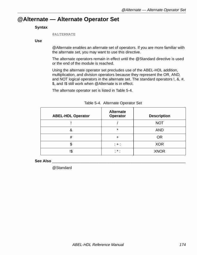
@Alternate — Alternate Operator Set
@Alternate — Alternate Operator SetSyntax
@ALTERNATE
Use
@Alternate enables an alternate set of operators. If you are more familiar withthe alternate set, you may want to use this directive.
The alternate operators remain in effect until the @Standard directive is usedor the end of the module is reached.
Using the alternate operator set precludes use of the ABEL-HDL addition,multiplication, and division operators because they represent the OR, AND,and NOT logical operators in the alternate set. The standard operators !, &, #,$, and !$ still work when @Alternate is in effect.
The alternate operator set is listed in Table 5-4.
See Also ______________________________________________________________
@Standard
Table 5-4. Alternate Operator Set
ABEL-HDL OperatorAlternateOperator Description
! / NOT
& * AND
# + OR
$ : + : XOR
!$ : * : XNOR
ABEL-HDL Reference Manual 174

@Carry — Maximum Bit-width for Arithmetic Functions
@Carry — Maximum Bit-width for Arithmetic FunctionsSyntax
@CARRYexpression ;
Use
expression A numeric expression.
The @Carry directive allows you to reduce the amount of logic required forprocessing large arithmetic functions by specifying how adders, counters, andcomparators are generated. The number generated by the expressionindicates the maximum bit-width to use when performing arithmetic functions.
For example, for an 8-bit adder, a @Carry statement with an expression whichresults in 2 would divide the 8-bit adder into four 2-bit adders, creatingintermediate nodes. This would reduce the amount of logic generated.
The statement:
@carry 1;
generates chains of one-bit adders and comparators for all subsequent adderand comparator equations (instead of the full look-ahead carry equationsnormally generated).
This directive automatically generates additional combinational nodes. Usedifferent values for the @Carry statement to specify the types of adders andcomparators required for the design. To specify that full lookahead carryshould be generated (the default if no @Carry has been specified) use thestatement:
@carry 0
Examples
@carry 2; "generate adder chain[s8..s0] = [.x.,a7..a0]+[.x.,b7..b0]
See Also ___________________________________________________________
= (Constant Declarations)“Constants” in Chapter 1, Language Structure”
ABEL-HDL Reference Manual 175

@Const — Constant Declarations
@Const — Constant DeclarationsSyntax
@CONSTid = expression ;
Use
id An identifier.
expression An expression.
@Const allows new constant declarations to be made in a source file outsidethe normal (and required) declarations section.
The @Const directive defines internal constants inside macros. Constantsdefined with @Const override previous constant declarations. You cannot use@Const to redefine an identifier that was used earlier in the source file assomething other than a constant (for example, a macro or pin).
Examples
@CONST count = count + 1;
See Also ___________________________________________________________
= (Constant Declarations)“Constants” in Chapter 1, Language Structure”
ABEL-HDL Reference Manual 176

@Dcset — Don't Care Set
@Dcset — Don't Care SetSyntax
@DCSET
Use
ABEL-HDL uses don't-care conditions to help optimize partially-specified logicfunctions. Partially-specified logic functions are those that have less than 2nsignificant input conditions, where n is the number of input signals. The@Dcset directive allows the optimization to use either 1 or 0 for don't cares tooptimize these functions.
See Also ___________________________________________________________
@OnsetIstype 'dc'?:= and ?= Assignment Operators
Truth_table“Precautions for Using Don't Care Optimization” inChapter 2, Design Considerations”
▲ CAUTION The @Dcset directive overrides Istype attributes 'dc', 'neg'and 'pos'.
ABEL-HDL Reference Manual 177

@Dcstate — State Output Don't Cares
@Dcstate — State Output Don't CaresSyntax
@DCSTATE
Use
When @Dcstate is specified, all unspecified state diagram states andtransitions are applied to the design outputs as don't cares. You must use thisoption in combination with @Dcset or with the 'dc' attribute.
See Also ___________________________________________________________
@DcsetIstype 'dc'
ABEL-HDL Reference Manual 178

@Exit — Exit Directive
@Exit — Exit DirectiveSyntax
@EXIT
Use
The @Exit directive stops processing of the source file with error bits set.(Error bits allow the operating system to determine that a processing error hasoccurred.)
ABEL-HDL Reference Manual 179

@Expr — Expression Directive
@Expr — Expression DirectiveSyntax
@EXPR [ { block } ] expression ;
Use
block A block.
expression An expression.
@Expr evaluates the given expression and converts it to a string of digits in thedefault base numbering system. This string and the block are then insertedinto the source file at the point where the @Expr directive occurs. Theexpression must produce a number.
@Expr can contain variable values and you can use it in loops with @Repeat.
Examples
@expr {ABC} ^B11 ;
Assuming that the default base is base ten, this example causes the text ABC3to be inserted into the source file.
ABEL-HDL Reference Manual 180

@If — If Directive
@If — If DirectiveSyntax
@IF expression { block }
Use
expression An expression.
block A block of text.
@If includes or excludes sections of code based on the value of anexpression. If the expression is non-zero (logical true), the block of code isincluded.
Dummy argument substitution is supported in the expression.
Examples
@if (A > 17) { C = D $ F ; }
ABEL-HDL Reference Manual 181

@Ifb — If Blank Directive
@Ifb — If Blank DirectiveSyntax
@IFB ( arg ) { block }
Use
arg An actual argument, or a dummy argument precededby a “?”
block A block of text.
@Ifb includes the text contained within the block if the argument is blank (if itcontains 0 characters).
Examples
@IFB (){text here is included with the rest of the source file.}
@IFB ( hello ) { this text is not included }
@IFB (?A) {this text is included if no value is substituted forA. }
See Also __________________________________________________________
“Arguments and Argument Substitution” inChapter 1, Language Structure”
ABEL-HDL Reference Manual 182

@Ifdef — If Defined Directive
@Ifdef — If Defined DirectiveSyntax
@IFDEF id { block }
Use
id An identifier.
block A block of text.
@Ifdef includes the text contained within the block, if the identifier is defined.
Examples
A pin 5 ;@ifdef A { Base = ^hE000 ; }"the above assignment is made because A was defined
ABEL-HDL Reference Manual 183

@Ifiden — If Identical Directive
@Ifiden — If Identical DirectiveSyntax
@IFIDEN ( arg1,arg2 ) { block }
Use
arg1,2 Actual arguments, or dummy argument namespreceded by a “?”
block A block of text.
The text in the block is included if arg1 and arg2 are identical.
Examples
@ifiden (?A,abcd) { ?A device 'P16R4'; }
A device declaration for a P16R4 is made if the actual argument substituted forA is identical to abcd.
ABEL-HDL Reference Manual 184

@Ifnb — If Not Blank Directive
@Ifnb — If Not Blank DirectiveSyntax
@IFNB ( arg ) { block }
Use
arg An actual argument, or a dummy argument namepreceded by a “?”
block A block of text.
@Ifnb includes the text contained within the block if the argument is not blank(if it contains more than 0 characters).
Examples
@IFNB () { ABEL-HDL source here is not included with the restof the source file. }
@IFNB ( hello ) { this text is included }
@IFNB (?A) {this text is included if a value is substituted forA}
ABEL-HDL Reference Manual 185
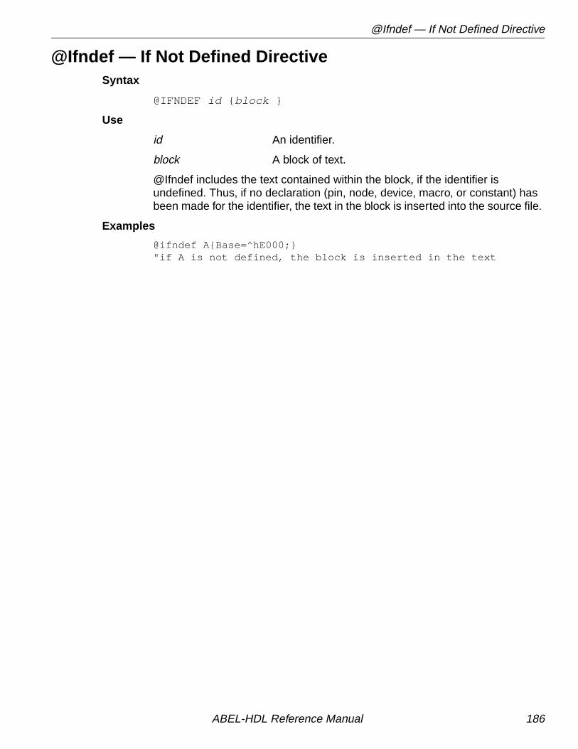
@Ifndef — If Not Defined Directive
@Ifndef — If Not Defined DirectiveSyntax
@IFNDEF id { block }
Use
id An identifier.
block A block of text.
@Ifndef includes the text contained within the block, if the identifier isundefined. Thus, if no declaration (pin, node, device, macro, or constant) hasbeen made for the identifier, the text in the block is inserted into the source file.
Examples
@ifndef A{Base=^hE000;}"if A is not defined, the block is inserted in the text
ABEL-HDL Reference Manual 186

@Ifniden — If Not Identical Directive
@Ifniden — If Not Identical DirectiveSyntax
@IFNIDEN ( arg1,arg2 ) { block }
Use
arg1,2 Actual arguments, or dummy argument namespreceded by a “?”
block A block of text.
The text in the block is included in the source file if arg1 and arg2 are notidentical.
Examples
@ifniden (?A,abcd) { ?A device 'P16R8'; }
A device declaration for a P16R8 is made if the actual argument substituted forA is not identical to abcd.
ABEL-HDL Reference Manual 187

@Include — Include Directive
@Include — Include DirectiveSyntax
@INCLUDEfilespec
Use
filespec A string specifying the name of a file.
@Include causes the contents of the specified file to be placed in theABEL-HDL source file. The inclusion begins at the location of the @Includedirective. The file specification can include an explicit drive or pathspecification that indicates where the file is found. If no drive or pathspecification is given, the default drive or path is used.
Examples
@INCLUDE 'macros.abl' "file specification@INCLUDE '\\incs\\macros.inc' "DOS paths require 2 slashes
See Also ___________________________________________________________
Library
ABEL-HDL Reference Manual 188

@Irp — Indefinite Repeat Directive
@Irp — Indefinite Repeat DirectiveSyntax
@IRP dummy_arg ( arg [, arg ]... ) { block }
Use
@Irp causes the block to be repeated in the source file n times, where nequals the number of arguments contained in the parentheses. Each time theblock is repeated, the dummy argument takes on the value of the nextsuccessive argument.
Examples
@IRP A (1, ^H0A,0){B = ?A ; }
results in:
B = 1 ;B = ^H0A ;B = 0 ;
which is inserted into the source file at the location of the @Irp directive.Note that multiple assignments to the same identifier result in an implicit OR.
Note that if the directive is specified like this:
@IRP A (1,^H0A,0){B = ?A ; }
the resulting text would be:
B = 1 ; B = ^H0A ; B = 0 ;
The text appears all on one line because the block in the @Irp definitioncontains no end-of-lines. Remember that end-of-lines and spaces aresignificant in blocks.
dummy_arg A dummy argument.
arg An actual argument, or a dummy argument namepreceded by a “?”
block A block of text.
ABEL-HDL Reference Manual 189

@Irpc — Indefinite Repeat, Character Directive
@Irpc — Indefinite Repeat, Character DirectiveSyntax
@IRPC dummy_arg ( arg ) { block }
Use
@Irpc causes the block to be repeated in the source file n times, where nequals the number of characters contained in arg. Each time the block isrepeated, the dummy argument takes on the value of the next character.
Examples
@IRPC A (Cat){B = ?A ;}
results in:
B = C ;B = a ;B = t ;
which is inserted into the source file at the location of the @Irpc directive.
dummy_arg A dummy argument.
arg An actual argument, or a dummy argument namepreceded by a “?”
block A block.
ABEL-HDL Reference Manual 190

@Message — Message Directive
@Message — Message DirectiveSyntax
@MESSAGE 'string '
Use
string Any string.
@Message sends the message specified in string to your monitor. You canuse this directive to monitor the progress of the parsing step of the compiler, oras an aid to debugging complex sequences of directives.
Examples
@message 'Includes completed'
ABEL-HDL Reference Manual 191

@Onset — No Don't Care's
@Onset — No Don't Care'sSyntax
@ONSET
Use
The @Onset directive disables the use of don't care input conditions foroptimization.
See Also ___________________________________________________________
@DcsetIstype 'dc'
ABEL-HDL Reference Manual 192

@Page — Page Directive
@Page — Page DirectiveSyntax
@PAGE
Use
Send a form feed to the listing file. If no listing is being created, @Page has noeffect.
ABEL-HDL Reference Manual 193

@Radix — Default Base Numbering Directive
@Radix — Default Base Numbering DirectiveSyntax
@RADIXexpr ;
Use
The @Radix directive changes the default base. The default is base 10(decimal). This directive is useful when you need to specify many numbers ina base other than 10. All numbers that do not have their base explicitly statedare assumed to be in the new base. (See “Numbers” inChapter 1, “Language Structure.”)
The new-specified default base stays in effect until another @Radix directiveis issued or until the end of the module is reached. Note that when a new@Radix is issued, the specification of the new base must be in the currentbase format.
When the default base is set to 16, all numbers in that base that begin with analphabetic character must begin with leading zeroes.
Examples
@radix 2 ; "change default base to binary@radix 1010 ; "change from binary to decimal
expr An expression that produces the number 2, 8, 10 or16 to indicate a new default base numbering.
ABEL-HDL Reference Manual 194

@Repeat — Repeat Directive
@Repeat — Repeat DirectiveSyntax
@REPEATexpr { block }
Use
expr A numeric expression.
block A block.
@Repeat causes the block to be repeated n times, where n is specified bythe constant expression.
Examples
The following use of the repeat directive,
@repeat 5 {H,}
results in the insertion of the text “H,H,H,H,H,” into the source file. The@Repeat directive is useful in generating long truth tables and sets of testvectors. Examples of @Repeat can be found in the example files.
ABEL-HDL Reference Manual 195

@Setsize — Set Indexing
@Setsize — Set IndexingSyntax
@SETSIZE [ expression ];
Purpose
The @Setsize directive generates a number corresponding to the number ofelements in the expression, which must be a set. This directive is useful forset indexing operations.
Example
@SETSIZE [a,b,c]
generates the number 3.
For set indexing, you can use the @setsize directive in macros in thefollowing manner:
high macro (s) {?S[@SETSIZE(?S);-1..@SETSIZE(?S);/2-1]};
The high macro returns the upper half of a set of any size (the high 4 bits of an8-bit set, for example).
See Also ___________________________________________________________
“Set Indexing” in Chapter 1, Language Structure”
✍ NOTE The terminating semicolons are required.
ABEL-HDL Reference Manual 196

@Standard — Standard Operators Directive
@Standard — Standard Operators DirectiveSyntax
@STANDARD
Use
The @Standard option resets the operators to the ABEL-HDL standard. Thealternate set is chosen with the @Alternate directive.
ABEL-HDL Reference Manual 197

Async_reset and Sync_reset
Async_reset and Sync_resetSyntax
SYNC_RESETsymbolic_state_id : input_expression ;ASYNC_RESETsymbolic_state_id : input_expression ;
Purpose
In symbolic state descriptions, the SYNC_RESET and ASYNC_RESETstatements specify synchronous or asynchronous state machine reset logic interms of symbolic states.
Use
symbolic_state_id An identifier used for reference to a symbolic state.
input_expression Any expression.
Examples
ASYNC_RESET Start : Reset ;
SYNC_RESET Start : Reset ;
See Also ___________________________________________________________
StateState_diagram“Using Symbolic State Descriptions” inChapter 2, Design Considerations”
ABEL-HDL Reference Manual 198
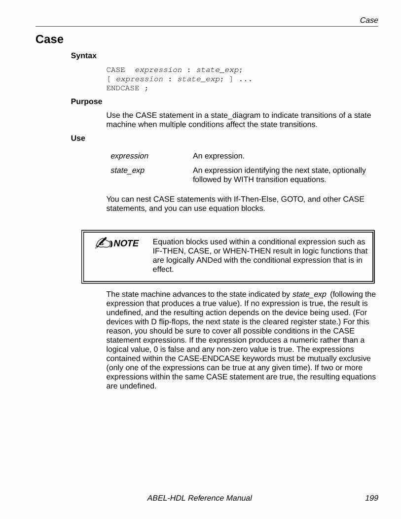
Case
CaseSyntax
CASE expression : state_exp ;[ expression : state_exp ; ] ...ENDCASE ;
Purpose
Use the CASE statement in a state_diagram to indicate transitions of a statemachine when multiple conditions affect the state transitions.
Use
You can nest CASE statements with If-Then-Else, GOTO, and other CASEstatements, and you can use equation blocks.
The state machine advances to the state indicated by state_exp (following theexpression that produces a true value). If no expression is true, the result isundefined, and the resulting action depends on the device being used. (Fordevices with D flip-flops, the next state is the cleared register state.) For thisreason, you should be sure to cover all possible conditions in the CASEstatement expressions. If the expression produces a numeric rather than alogical value, 0 is false and any non-zero value is true. The expressionscontained within the CASE-ENDCASE keywords must be mutually exclusive(only one of the expressions can be true at any given time). If two or moreexpressions within the same CASE statement are true, the resulting equationsare undefined.
expression An expression.
state_exp An expression identifying the next state, optionallyfollowed by WITH transition equations.
✍ NOTE Equation blocks used within a conditional expression such asIF-THEN, CASE, or WHEN-THEN result in logic functions thatare logically ANDed with the conditional expression that is ineffect.
ABEL-HDL Reference Manual 199

Case
Examples
"Mutually exclusive Case statementcase a == 0 : 1 ; a == 1 : 2 ; a == 2 : 3 ; a == 3 : 0 ;endcase ;
"Not mutually exclusive Case statementcase (a == 0) : 1 ; (a == 0) & (B == 0) : 0 ;endcase ;
See Also ___________________________________________________________
State_diagramGotoIf-then-elseWith
ABEL-HDL Reference Manual 200

Cycle
CycleSyntax
CYCLE signal_name ( logic_value , integer) ( logic_value , integer) [( logic_value ), integer)];
Use
logic_value The logic 1fsvalue can be either 0 or 1.
This keyword specifies the signal to repeat until the end of simulation. Thedefault time unit is nano-second.
Example
cycle clk1 (0,3ns) (1,5ns);
See Als o ___________________________________________________________
Test_vectorsWaitflicker.abl
ABEL-HDL Reference Manual 201

Constant Declarations
Constant DeclarationsSee = (Constant Declarations) .
ABEL-HDL Reference Manual 202

Declarations
DeclarationsSyntax
DECLARATIONSdeclarations
Purpose
The declarations keyword allows you to declare declarations (such as sets orother constants) in any part of the ABEL-HDL source file.
Use
The DECLARATIONS keyword is not necessary for declarations immediatelyfollowing the module and/or title statement(s).
Examples
An example of declared equations is shown below:
module castle moat device 'P16V8C'; "declarations implied A,B pin 1,2; Out1 pin 15 istype 'com';Equations Out1 = A & B;
Declarations "declarations keyword required C,D,E,F pin 3,4,5,6; Out2 pin 16 istype 'com'; Temp1 = C & D; Temp2 = E & F;
Equations Out2 = Temp1 # Temp2;end;
declarations You can use any declarations after theDECLARATIONS keyword.
ABEL-HDL Reference Manual 203

Device
DeviceSyntax
device_id DEVICE real_device ;
Purpose
The device declaration statement associates the device name used in amodule with an actual programmable logic device on which designs areimplemented.
Use
The device declaration is optional.
You should give device identifiers, used in device declarations, valid file namessince JEDEC files are created by appending the extension .jed to theidentifier. The architecture name of the programmable logic device is indicatedby the string, real_device.
The ending semicolon is required.
device_id An identifier used for the programmer to load filenames.
real_device A string describing the architecture name of thereal device represented by device_id.
ABEL-HDL Reference Manual 204

End
EndSyntax
END module_name
Purpose
The end statement denotes the end of the module.
Use
The end statement can be followed by the module name. For multi-modulesource files, the module name is required.
ABEL-HDL Reference Manual 205

Equations
EquationsSyntax
EQUATIONSelement [?]= condition ;element [?]:= condition ;when-then-else_statement ;<inst_name > < macro_name > ([< mcr_port >]{,[< mcr_port >]}*);
Purpose
The equations statement defines the beginning of a group of equationsassociated with a device.
Use
Equations specify logic functions with an extended form of Boolean algebra.
A semicolon is required after each equation.
The equations following the equation statement are equations as described inChapter 1, “Language Structure.”
The syntax
<inst_name > < macro_name > ([< mcr_port >]{,[< mcr_port >]}*);
is enhanced to support Lattice system macros in ABEL-HDL.
When the Lattice system macros are being called, the user defined macro portnumbers must match the macro need.
The <mcr_port> is the signal(s) in the current design. Two consecutivecommas mean a macro port is not connected. The output port of a macro canbe dangled, while the input ports or bidirectional ports cannot be dangled.
condition An expression.
element An identifier naming a signal, set of signals, oractual set to which the value of the expression isassigned.
expression An expression.
=, :=, ?= and ?:= Combinational and registered (pin-to-pin) on-setand dc-set assignment operators.
when-then-else When-then-else statements.
inst_name Identifier.
macro_name Identifier; Lattice system macro name.
mcr_port Signal(s), signal set, or boolean expressions.
ABEL-HDL Reference Manual 206

Equations
Boolean expressions and special constants can be used on Lattice macro’sinput ports, while they cannot be used on output or bidirectional ports.Inversion on output ports is allowed.
Examples
A sample equations section follows:
equationsA = B & C # A ;[W,Y] = 3 ;!F = (B == C) ;Output.D = In1 # In2b1 cbu14 ([q0..q3], , ci, clk, cd); // Lattice system macro // cbu14 used
See Also ___________________________________________________________
When-then-elseModuleState_diagramTruth_table“Operators, Expressions, and Equations” inChapter 1, Language Structure”
▲ CAUTION Use the := and ?:= operators only when writing pin-to-pinregistered equations. Use the = and ?= assignmentoperators for registered equations with detailed dotextensions.
ABEL-HDL Reference Manual 207
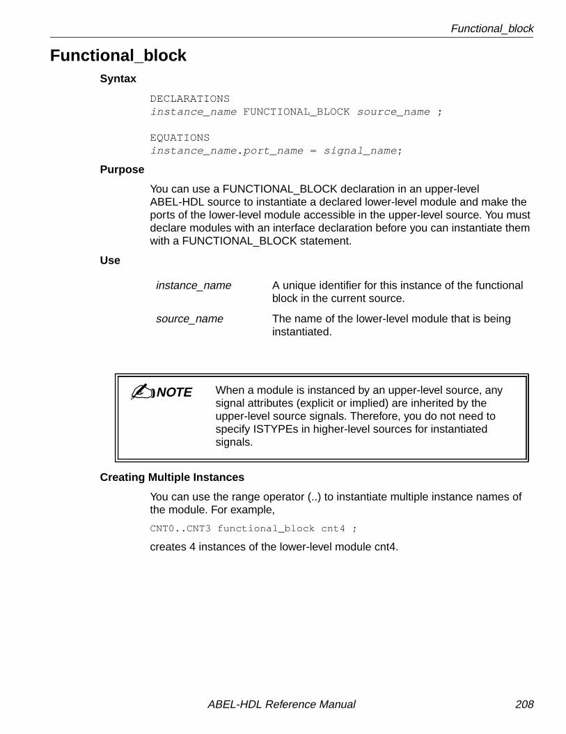
Functional_block
Functional_blockSyntax
DECLARATIONSinstance_name FUNCTIONAL_BLOCK source_name ;
EQUATIONSinstance_name . port_name = signal_name ;
Purpose
You can use a FUNCTIONAL_BLOCK declaration in an upper-levelABEL-HDL source to instantiate a declared lower-level module and make theports of the lower-level module accessible in the upper-level source. You mustdeclare modules with an interface declaration before you can instantiate themwith a FUNCTIONAL_BLOCK statement.
Use
Creating Multiple Instances
You can use the range operator (..) to instantiate multiple instance names ofthe module. For example,
CNT0..CNT3 functional_block cnt4 ;
creates 4 instances of the lower-level module cnt4.
instance_name A unique identifier for this instance of the functionalblock in the current source.
source_name The name of the lower-level module that is beinginstantiated.
✍ NOTE When a module is instanced by an upper-level source, anysignal attributes (explicit or implied) are inherited by theupper-level source signals. Therefore, you do not need tospecify ISTYPEs in higher-level sources for instantiatedsignals.
ABEL-HDL Reference Manual 208

Functional_block
Mapping Ports to Signals
Signal names are mapped to port names, using equations (similar to wiring thesignals on a schematic). You need to specify only the signals used in theupper-level source, if default values have been specified in the lower-levelmodule interface statement. See “Interface (lower-level)” in this chapter formore information on setting default values.
To specify the signal wiring, map signal names to the lower-level module portnames with dot extension notation. There are three kinds of wire: input,output, and interconnect.
Examples
module counter;
cnt4 interface (ce, ar, clk -> [q0..q3]); // cnt4's top-level interface declaration.
CNT0 functional_block cnt4; // Four instances of cnt4.
Clk, AR, CE pin;Q0..Q3 pin;
equations CNT0.[clk, ar, ce] = [Clk; AR, CE];
// Connecting to Clk, AR, and CE inputs. [Q0..Q3] = CNT0.[q0..q3]; // Connecting to Q0..Q3 outputs.end
Figure 5-10 shows how the above ABEL-HDL file wires the upper-levelsource's signals to the lower-level module's ports. Note that the above fileinstantiates four instances of cnt4 , but only one (CNT0) is wired.
Input Wire Connects lower-level module inputs to upper-levelsource inputs.
Instance.port = input
Output Wire Connects upper-level source outputs to lower-levelmodule outputs.
output = instance.port
Interconnect Wire Connects the outputs of one instance of alower-level module to another instance's inputs.
Instance0.port = instance1.port
ABEL-HDL Reference Manual 209

Functional_block
Overriding Default Values
You can override the default values given in a lower-level module's interfacestatement by specifying default equations in the higher-level source. Forexample, if you have specified a default value of 1 for the signal ce in interfacecnt4 (but in instance CNT0, you want ce to be 0), you would write:
CNT0.ce = 0 ;
This equation overrides the 1 with a 0. If you override the default values, youmay want to re-optimize the post-linked design.
Figure 5-10. Wiring of CNT0
Unused Outputs (No Connects)
If you do not want to use a lower-level module's outputs, specify them as NoConnects (NC) by not wiring up the port to a physical pin. For example, to make a3-bit counter out of a 4-bit counter in the upper-level source, you might use thefollowing wiring equations:
q2..q0 pin ; "upper-level signalsEquations [q2..q0] = CNT_A.[q2..q0]
See Also ___________________________________________________________
Interface (top-level)“Hierarchy in ABEL-HDL” in Chapter 2, Design Considerations”
ABEL-HDL Reference Manual 210

Fuses
FusesSyntax
FUSESfuse_number = fuse_value ;
orFUSES[ fuse_number_set ] = fuse_value ;
Purpose
The FUSES section explicitly declares the state of any fuse in the targeteddevice.
Use
The FUSES statement provides device-specific information, and precludeschanging devices without editing the statement in the source file.
Fuse values that appear on the right side of the = symbol can be any number.If a single fuse number is specified on the left side of the = symbol, the leastsignificant bit (LSB) of the fuse value is assigned to the fuse. A 0 indicates anintact fuse and a 1 indicates a blown fuse. In the case of multiple fusenumbers, the fuse value is expanded to a binary number and truncated orgiven leading zeros to obtain fuse values for each fuse number.
ABEL-HDL has a limit of 128 fuses per statement, due to the set sizelimitations.
fuse_number The fuse number obtained from the logic diagram ofthe device.
fuse_number_set The set of fuse numbers (contained in squarebrackets).
fuse_value The number indicating the state of fuse(s).
▲ CAUTION When fuse states are specified using the fuses section,the resulting fuse values supersede the fuse valuesobtained through the use of equations, truth tables andstate diagrams, and affect device simulation accordingly.
ABEL-HDL Reference Manual 211

Fuses
Examples
FUSES3552 = 1 ;[3478...3491] = ^Hff;
ABEL-HDL Reference Manual 212

Goto
GotoSyntax
GOTOstate_exp ;
Purpose
The GOTO statement is used in the state_diagram section to cause anunconditional transition to the state indicated by state_exp.
Use
GOTO statements can be nested with IF-THEN-ELSE and CASE statements.
Examples
GOTO 0 ; "goto state 0GOTO x+y ; "goto the state x + y
See Also ___________________________________________________________
State_diagramCaseIf-then-elseWith
state_exp An expression identifying the next state, optionallyfollowed by WITH transition equations.
ABEL-HDL Reference Manual 213

If-Then-Else
If-Then-ElseSyntax
IF exp THEN state_exp[ ELSE state_exp ] ;
Chained IF-THEN-ELSE:
IF expr THEN state_exp ELSE IF exp THEN state_exp
ELSE state_exp ;
Nested IF-THEN-ELSE:
IF exp THEN state_exp ELSE IF exp THEN IF exp THEN state_exp
ELSE state_exp ELSE state_exp ;
Nested IF-THEN-ELSE with Blocks:
IF exp THEN{ IF exp THEN state_exp
IF exp THEN state_exp}ELSE state_exp ;
Purpose
The if-then-else statements are used in the state_diagram section todescribe the progression from one state to another.
Use
exp An expression.
state_exp An expression or block identifying the next state,optionally followed by WITH transition equations.
▲ CAUTION IF-THEN-ELSE is only supported within aSTATE_DIAGRAM description. Use WHEN-THEN-ELSEfor equations.
ABEL-HDL Reference Manual 214

If-Then-Else
The expression following the IF keyword is evaluated, and if the result is true,the machine goes to the state indicated by the state_exp, following the THENkeyword. If the result of the expression is false, the machine jumps to the stateindicated by the ELSE keyword.
Any number of IF statements may be used in a given state, and the ELSEclause is optional. The indenting and formatting of an IF-THEN-ELSEstatement is not significant: breaking a complex transition statement acrossmany lines (and indenting) improves readability.
IF-THEN-ELSE statements can be nested with GOTO, CASE, and WITHstatements. IF-THEN-ELSE and CASE statements can also be combined andnested.
Chained IF-THEN-ELSE Statements:
Any number of IF-THEN-ELSE statements can be chained, but the finalstatement must end with a semicolon. The chained IF-THEN-ELSE statementis intended for situations where the conditions are not mutually exclusive. TheCASE statement more clearly expresses the same function as chainedmutually-exclusive IF-THEN-ELSE statements.
Chained IF-THEN-ELSE statements can provide multiway branching transitionlogic. For example, multiple IF-THEN-ELSE statements can be chained todescribe a three-way branch in the following manner:
STATE S0: IF (address < ^h0400) THEN S0 ELSE IF (address <= ^hE100) THEN S2 ELSE S1;
Examples
if A==B then 2 ; "if A equals B goto state 2if x-y then j else k; "if x-y is not 0 goto j, else goto kif A then b*c; "if A is true (non-zero) goto state b*c
✍ NOTE Equation Blocks used within a conditional expression (such asIF-THEN, CASE, or WHEN-THEN) results in logic functionsthat are logically ANDed with the conditional expression that isin effect.
ABEL-HDL Reference Manual 215

If-Then-Else
Chained IF-THEN-ELSE
if a then 1 elseif b then 2 elseif c then 3 else 0 ;
Nested IF-THEN-ELSE with Blocks
IF (Hold) THEN{ IF (!RESET) THEN State1 ; IF (Error) THEN State2 ;}ELSE State3 ;
Nested IF-THEN-ELSE Statements
A complex state transition could be written with nested transitions in thefollowing manner:
STATE S0: CASE (select == 1): IF (address == ^h0100) THEN S16 ELSE IF (address > ^hE100) THEN S17 ELSE S0; (select == 2): S2; (select == 3): IF (address <= ^hE100) THEN IF (reset) THEN S3 ELSE S0; ELSE S17; (select == 0): S0; ENDCASE;
See Also ___________________________________________________________
State_diagramCaseGotoWith
ABEL-HDL Reference Manual 216
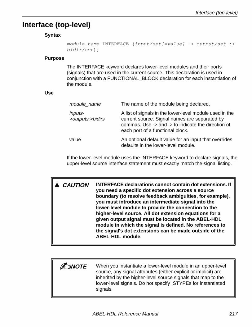
Interface (top-level)
Interface (top-level)Syntax
module_name INTERFACE (input/set[=value] -> output/set :>bidir/set );
Purpose
The INTERFACE keyword declares lower-level modules and their ports(signals) that are used in the current source. This declaration is used inconjunction with a FUNCTIONAL_BLOCK declaration for each instantiation ofthe module.
Use
If the lower-level module uses the INTERFACE keyword to declare signals, theupper-level source interface statement must exactly match the signal listing.
module_name The name of the module being declared.
inputs->outputs:>bidirs
A list of signals in the lower-level module used in thecurrent source. Signal names are separated bycommas. Use -> and :> to indicate the direction ofeach port of a functional block.
value An optional default value for an input that overridesdefaults in the lower-level module.
▲ CAUTION INTERFACE declarations cannot contain dot extensions. Ifyou need a specific dot extension across a sourceboundary (to resolve feedback ambiguities, for example),you must introduce an intermediate signal into thelower-level module to provide the connection to thehigher-level source. All dot extension equations for agiven output signal must be located in the ABEL-HDLmodule in which the signal is defined. No references tothe signal's dot extensions can be made outside of theABEL-HDL module.
✍ NOTE When you instantiate a lower-level module in an upper-levelsource, any signal attributes (either explicit or implicit) areinherited by the higher-level source signals that map to thelower-level signals. Do not specify ISTYPEs for instantiatedsignals.
ABEL-HDL Reference Manual 217

Interface (top-level)
Examples
module top;cnt4 interface (ce,ar,clk -> [q3..q0])
Map port names to signal names with equations. See “Functional_block.”
See Also ___________________________________________________________
Functional_block“Hierarchy in ABEL-HDL” in Chapter 2, Design Considerations”
ABEL-HDL Reference Manual 218

Interface (lower-level)
Interface (lower-level)Syntax
MODULEmodule_nameINTERFACE ( input/set [= port_value ] -> output/set [:>bidir/set ]);
Purpose
The INTERFACE declaration is optional for lower-level modules. Use theINTERFACE declaration in lower-level modules to assign a default port list andinput values for the module when instantiated in higher-level ABEL-HDLsources. If you use the interface statement in an instantiated module, youmust declare the signals and sets in the upper-level source in the same orderand grouping as given in the INTERFACE statement in the lower-level module.Interface (lower-level source).
Declaring signals in the lower-level module, although optional, does allow thecompiler to check for signal declaration mismatches and therefore reduces thepossibility of wiring errors.
Use
Declared Signals
Declared signals can be a list of lower-level pins, sets, or a combination ofboth. The following constraints apply to the different signal types:
module_name The standard module statement.
signal/set Signals or sets in the lower-level module used asports to higher-level sources. Use -> and :> toindicate the direction of each port of a functionalblock. Use commas to separate groups of signals
port_value The default value for the port for input signals only.Default values do not apply to output andbidirectional signals.
ABEL-HDL Reference Manual 219

Interface (lower-level)
Signal Type Constraints
Input Default values must be binary if applied to anindividual bit, or any positive integer applied to a set.All inputs must be listed.
Output Unlisted outputs are interpreted as No connects(NC). Unlisted, fed-back outputs are interpreted asnodes in the upper-level source, following thenaming convention instance_name/node_name
Bidirectional Listing bidirectional signals is optional, except forthose with output enable (OE). If you specifybidirectional signals, the compiler checks for invalidwire connections.
▲ CAUTION INTERFACE declarations cannot contain dot extensions. Ifyou need a specific dot extension across a sourceboundary (to resolve feedback ambiguities, for example),you must introduce an intermediate signal into thelower-level module to provide the connection to thehigher-level source. All dot extension equations for agiven output signal must be located in the ABEL-HDLmodule in which the signal is defined. No references tothe signal's dot extensions can be made outside of theABEL-HDL module.
✍ NOTE When you instantiate a lower-level module in a higher-levelsource, any signal attributes (explicit or implicit) are inheritedby the higher-level source signals that map to the lower-levelsignals. Do not specify ISTYPEs for instantiated signals.
ABEL-HDL Reference Manual 220

Interface (lower-level)
Unlisted Signals
If you do not list some signals of the lower-level module in the interfacestatement, the following rules apply:
Examples
The following interface statement declares inputs ce, ar, and clk (giving defaultvalues for two of them) and outputs q3 through q0.
module cnt4 interface (ce=1,ar=1,clk -> [q3..q0]) ;
Specifying default values allows you to instantiate cnt4 without declaring thece and ar inputs in the upper-level source. If you do not declare these inputs,they are replaced with the constants 1 and 0, respectively. Since theseconstants may affect optimization, you may need to re-optimize the lower-levelmodule with the constants.
See Also ___________________________________________________________
Interface (top-level)Functional_block“Hierarchy in ABEL-HDL” in Chapter 2, Design Considerations”
Unlisted Pins Are: The Compiler Interprets Them As:
Inputs orBidirectionals withOE
Errors
Outputs No Connects (NC), and they can be removed
Feedback outputs Nodes in the upper-level source, following thenaming convention: instance_name/node_name
✍ NOTE Supported default values are 1, 0, or X (don't care). You cangive default values for a set with a positive integer, and eachdigit of the integer's binary form supplies the default value forthe corresponding signal in the set.
ABEL-HDL Reference Manual 221
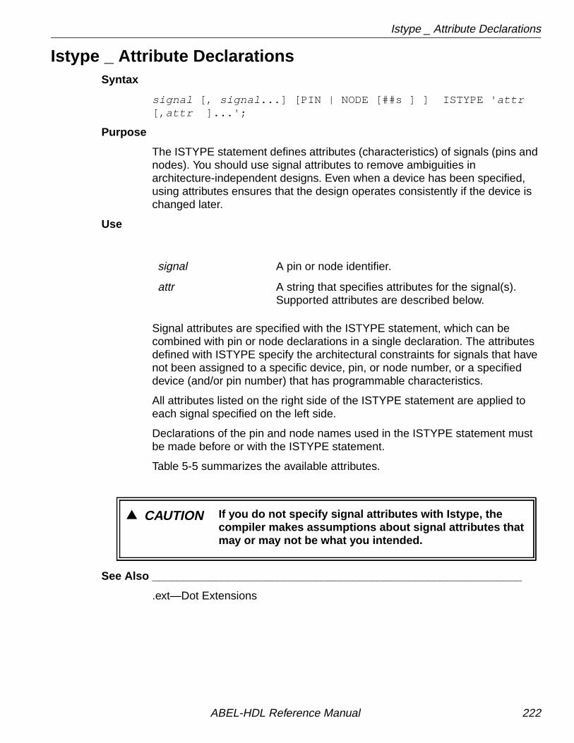
Istype _ Attribute Declarations
Istype _ Attribute DeclarationsSyntax
signal [, signal ...] [PIN | NODE [##s ] ] ISTYPE ' attr[, attr ]...';
Purpose
The ISTYPE statement defines attributes (characteristics) of signals (pins andnodes). You should use signal attributes to remove ambiguities inarchitecture-independent designs. Even when a device has been specified,using attributes ensures that the design operates consistently if the device ischanged later.
Use
Signal attributes are specified with the ISTYPE statement, which can becombined with pin or node declarations in a single declaration. The attributesdefined with ISTYPE specify the architectural constraints for signals that havenot been assigned to a specific device, pin, or node number, or a specifieddevice (and/or pin number) that has programmable characteristics.
All attributes listed on the right side of the ISTYPE statement are applied toeach signal specified on the left side.
Declarations of the pin and node names used in the ISTYPE statement mustbe made before or with the ISTYPE statement.
Table 5-5 summarizes the available attributes.
See Also ___________________________________________________________
.ext—Dot Extensions
signal A pin or node identifier.
attr A string that specifies attributes for the signal(s).Supported attributes are described below.
▲ CAUTION If you do not specify signal attributes with Istype, thecompiler makes assumptions about signal attributes thatmay or may not be what you intended.
ABEL-HDL Reference Manual 222

Istype _ Attribute Declarations
Table 5-5. Attributes
Dot Ext. Arch. Indep. Description
'buffer' No Inverter in Target Device.
'collapse' Collapse (remove) this signal.1
'com' Combinational output.
'dc' ✓ Unspecified logic is don't care.2
'invert' Inverter in Target Device.
'keep' Do not collapse this signal from equations.1
'neg' ✓ Unspecified logic is 1.2
'pos' ✓ Unspecified logic is 0.2
'retain' ✓ Do not minimize this output. Preserve redundantproduct terms.3
'reg' ✓ Clocked Memory Element.
'reg_d' D Flip-flop Clocked Memory Element.
'reg_g' D Flip-flop Gated Clock Memory Element.
'reg_jk' JK Flip-flop Clocked Memory Element.
'reg_sr' SR Flip-flop Clocked Memory Element.
'reg_t' T Flip-flop Clocked Memory Element.
'xor' XOR Gate in Target Device.1If neither 'keep' nor 'collapse' is specified, the optimization or fitter programs can keep or collapse the signal as needed to optimize the circuit.2The 'dc,' 'neg,' and 'pos' attributes are mutually exclusive.3The 'retain' attribute only controls optimization performed by ABEL-HDL Compile Logic. Topreserve redundant product terms, you must also specify no reduction for the Reduce Logic and
fitting (place and route) programs.
ABEL-HDL Reference Manual 223

Istype _ Attribute Declarations
' buffer ' The target architecture does not have an inverter between theassociated flip-flop (if any) and the actual output pin.
' invert ' The target architecture has an inverter between the associated flip-flop (if any) and the actual output pin.
Control of output inversion in devices is accomplished through theuse of the 'invert' or 'buffer' attributes. These attributes enforce theexistence ('invert') or non-existence ('buffer') of a hardwareinverter at the device pin associated with the output signal specified.
In registered devices, the 'invert' attribute ensures that an inverter islocated between the output pin and its associated register output.
' collapse ' Collapse (remove) this combinational node. If neither 'keep' nor'collapse' is specified, the compiler will keep or collapse the node forbest optimization. In the following example, signal b is given the'collapse' attribute:
module coll_ba,c,d,e pin ;b node istype 'collapse'
equationsa = b & e;b = c & d;end
The resulting equation collapses b out of the equations:
a = c & d & e ;
' keep ' Do not collapse this combinational node from equations. In theexample under 'collapse,' b would be retained.
' com' Specifies a combinational symbol.
✍ NOTE Ensuring an inverter is important for both pin-to-pin anddetailed design descriptions because the location of theinverter affects a register's reset, preset, preload, and powerupbehavior as observed on the associated output pin.
ABEL-HDL Reference Manual 224

Istype _ Attribute Declarations
'dc,' 'neg,' and 'pos'
These attributes control the value of unspecified logic in yourdesign, and are mutually exclusive. The values they specify areshown below:
The 'dc' attribute is equivalent to the @Dcset directive, except itoperates on signals instead of applying to a whole section.
' reg ' The signal specified is a registered output. Equations, statediagrams, and truth tables will generate logic for a D-type flip-flop,normalized to take into account any inverters in the target device.
' reg_d ' The signal specified is a registered output. Equations, statediagrams, and truth tables will generate logic for a D-type flip-flop,but you must specify if the output is inverted in the target device(with attribute 'invert' or 'buffer').
' reg_g ' The signal specified is a registered output. Equations, statediagrams, and truth tables will generate logic for a D-type flip-flop,but you must specify if the output is inverted in the target device(with attribute 'invert' or 'buffer'). Write equations and truth tablesusing the .D and .CE dot extensions when you use this attribute.
Istype Attribute Unspecified Logic is
'dc' X (don't care)
'neg' 1
'pos' 0
✍ NOTE The 'neg' or 'pos' attribute is implied if a device is specified. Forexample, 'neg' is implied if the device output is inverted.
▲ CAUTION The @Dcset directive overrides 'dc,' 'neg,' and 'pos'.
ABEL-HDL Reference Manual 225

Istype _ Attribute Declarations
' reg_jk ' The signal specified is a JK-type registered output. State diagramsgenerate logic for this register type, but you must specify if theoutput is inverted in the target device (with attribute 'invert' or'buffer'). Write Equations and truth tables using the .J and .K dotextensions when you use this attribute.
' reg_sr ' The signal specified is an SR-type registered output. Statediagrams will generate logic for this register type, but you mustspecify if the output is inverted in the target device (with attribute'invert' or 'buffer'). Write equations and truth tables using the .S and.R dot extensions when you use this attribute.
' reg_t ' The signal specified is a T-type registered output. State diagramswill generate logic for this register type, but you must specify if theoutput is inverted in the target device (with attribute 'invert' or'buffer'). Write equations and truth tables using the .T dot extensionwhen you use this attribute.
' retain ' Do not minimize this output. Preserve redundant product terms forthe signal.
' xor ' The signal specified will be implemented using an XOR gate fed bytwo sum-of-products logic circuits. If you use XOR operators in thedesign equations for this output (or if you use high-level operatorsthat result in XOR operations), then one XOR operator is retainedthrough optimization. Use this attribute if you are implementing yourdesign in an architecture featuring XOR gates.
Examples
F0, A istype 'invert, reg' ;
This declaration statement defines F0 and A as inverted registered outputs.You must define both F0 and A earlier in the module. The following signaldeclarations are all supported:
q3,q2,q1,q0 NODE ISTYPE 'reg_SR';Clk,a,b,c PIN 1,2,3,4;reset PIN;reset ISTYPE 'com';Output PIN 15 ISTYPE 'reg,invert';
See Also ___________________________________________________________
.extPinNode“Dot Extensions” , “Attribute Assignment” , and “XOR Factors” inChapter 1, Language Structure”
ABEL-HDL Reference Manual 226

Library
LibrarySyntax
LIBRARY ' name' ;
Purpose
The LIBRARY statement causes the contents of the indicated file to beinserted in the ABEL-HDL source file. The insertion begins at the LIBRARYstatement.
Use
The file extension of '.inc' is appended to the name specified, and theresulting file name is searched for. If no file is found, the abel5lib.inc libraryfile is searched.
See Also ___________________________________________________________
Module@Include
name A string that specifies the name of the library file,excluding the file extension.
ABEL-HDL Reference Manual 227

Macro
MacroSyntax
macro_id MACRO [ ( dummy_arg [, dummy_arg ]... ) ] { block };
Purpose
The MACRO declaration statement defines a macro. Macros are used toinclude ABEL-HDL code in a source file without typing or copying the codeeverywhere it is needed.
Use
macro_id An identifier naming the macro.
dummy_arg A dummy argument.
block A block.
A macro is defined once in the declarations section of a module and then usedanywhere within the module as frequently as needed. Macros can be usedonly within the module in which they are declared.
Wherever the macro_id occurs, the text in the block associated with that macrois substituted. With the exception of dummy arguments, all text in the block(including spaces and end-of-lines) is substituted exactly as it appears in theblock.
When debugging your source file, you can use the -list expand option toexamine macro statements. The -list expand option causes the parsed andexpanded source code (and the macros and directives that caused code to beadded to the source) to be written to the listing file.
Macros and Declared Equations
Use declared equations for constant expressions (instead of macros) forfaster processing. The file, mac.abl , in Figure 5-11 demonstrates thedifference:
ABEL-HDL Reference Manual 228

Macro
Figure 5-11. Differences Between MACRO and Declared Equations
module mactitle 'Demonstrates difference between MACRO and declared equations' mac device 'P16H8'; A,B,C pin 1,2,3; X1,X2,X3 pin 14,15,16 istype 'com'; Y1 macro {B # C}; Y2 = B # C;
equations X1 = A & Y1; X2 = A & (Y1); X3 = A & Y2;
// Note: Because Y1 is a text replacement macro the// equation for X1 will expand to A & B # C. If the// desired function was A & (B # C) use parentheses// around the macro or use a subexpression (Y1=B#C)// instead of the macro in the declarations.
// The macro could also be written Y1 macro {(B # C)};
test_vectors ([A,B,C] -> [X1,X2,X3]) [0,0,0] -> [ 0, 0, 0]; [0,0,1] -> [ 1, 0, 0]; [0,1,0] -> [ 0, 0, 0]; [0,1,1] -> [ 1, 0, 0]; [1,0,0] -> [ 0, 0, 0]; [1,0,1] -> [ 1, 1, 1]; [1,1,0] -> [ 1, 1, 1]; [1,1,1] -> [ 1, 1, 1];end
ABEL-HDL Reference Manual 229

Macro
Examples
The dummy arguments used in the MACRO declaration allow different actualarguments to be used each time the macro is referenced. Dummy argumentsare preceded by a “?” to indicate that an actual argument is substituted for thedummy by the compiler.
The equation,
NAND3 MACRO (A,B,C) { !(?A & ?B & ?C) } ;
declares a macro named NAND3 with the dummy arguments A, B, and C. Themacro defines a three-input NAND gate. When the macro identifier occurs inthe source, actual arguments for A, B, and C are supplied.
For example, the equation
D = NAND3 (Clock,Hello,Busy) ;
brings the text in the block associated with NAND3 into the code, with Clocksubstituted for ?A, Hello for ?B, and Busy for ?C.This results in:
D = !( Clock & Hello & Busy ) ;
which is the three-input NAND.
The macro NAND3 has been specified by a Boolean equation, but it couldhave been specified using another ABEL-HDL construct, such as the truthtable shown here:
NAND3 MACRO (A,B,C,Y){ TRUTH_TABLE ( [?A ,?B ,?C ] -> ?Y ) [ 0 ,.X.,.X.] -> 1 ; [.X., 0 ,.X.] -> 1 ; [.X.,.X., 0 ] -> 1 ; [ 1 , 1 , 1 ] -> 0 ; } ;
In this case, the line,
NAND3 (Clock,Hello,Busy,D)
causes the text,
TRUTH_TABLE ( [Clock,Hello,Busy] -> D ) [ 0 , .X. ,.X. ] -> 1 ; [ .X. , 0 ,.X. ] -> 1 ; [ .X. , .X. , 0 ] -> 1 ; [ 1 , 1 , 1 ] -> 0 ;
to be substituted into the code. This text is a truth table definition of D,specified as the function of three inputs, Clock, Hello, and Busy. This is thesame function as that given by the Boolean equation above. The truth tableformat is discussed under TRUTH_TABLE.
ABEL-HDL Reference Manual 230

Macro
Other examples of macros:
"macro with no dummy argumentsnodum macro { W = S1 & S2 & S3 ; } ;
onedum MACRO (d) { !?d } ; "macro with 1 dummy argument
and when macros are called in logic descriptions:
nodumX = W + onedum(inp) ;Y = W + onedum( )C ; "note the blank actual argument
resulting in:
"note leading space from block in nodum W = S1 & S2 & S3 ;X = W + ! inp ;Y = W + ! C ;
Recursive macro references (when a macro definition refers to itself) are notsupported, and the compiler halts abnormally. If errors appear after the firstuse of a macro and the errors cannot be easily explained otherwise, check fora recursive macro reference by examining the listing file.
See Also ___________________________________________________________
= (Constant Declarations)“Arguments and Argument Substitution” inChapter 1, Language Structure”
ABEL-HDL Reference Manual 231

Module
ModuleSyntax
MODULEmodname [ ( dummy_arg [, dummy_arg ] ... ) ]
Purpose
The MODULE statement defines the beginning of a module and must bepaired with an END statement that defines the module's end.
Use
modname An identifier naming the module.
dummy_arg Dummy arguments.
The optional dummy arguments allow actual arguments to be passed to themodule when it is processed. The dummy argument provides a name to referto within the module. Anywhere in the module where a dummy argument isfound preceded by a “?”, the actual argument value is substituted.
Examples
MODULE MY_EXAMPLE (A,B) : C = ?B + ?A
In the module named MY_EXAMPLE, C takes on the value of “A + B” where Aand B contain actual arguments passed to the module when the languageprocessor is invoked.
See Also ___________________________________________________________
TitleInterface (submodule)End“Arguments and Argument Substitution” inChapter 1, Language Structure”
ABEL-HDL Reference Manual 232

Node
NodeSyntax
[!] node_id [,[!] node_id ...] NODE [ node# [,node# ]] [ISTYPE' attributes ' ];
Purpose
The NODE keyword declares signals assigned to buried nodes.
Use
You can use the range operator (..) to declare sets of nodes. The endingsemicolon is required after each declaration.
When lists of node_id and node # are used in one node declaration, there is aone-to-one correspondence between the identifiers and numbers.
The following example declares three nodes A, B, and C.
A, B, C NODE ;
The node attribute string, Istype ' attributes ,' should be used to specify nodeattributes. Since a node declaration is only required in a detailed description,use detailed attributes, not pin-to-pin attributes. The ISTYPE statement andattributes are discussed under Istype.
The node declaration,
B NODE istype 'reg' ;
specifies that node B is a buried flip-flop.
node_id An identifier used for reference to a node in a logicdesign.
node# The node number on the real device.
attributes A string that specifies node attributes for deviceswith programmable nodes. Any number of attributescan be listed, separated by commas. Attributes arelisted in Table 1-9 under “Attribute Assignment” inChapter 1, “Language Structure.”
✍ NOTE Using the Node keyword does not restrict a signal to a buriednode. A signal declared with NODE can be assigned to adevice I/O pin by a device fitter.
ABEL-HDL Reference Manual 233

Node
Example
a0..a3 node 22..25;
assigns a0, a1, a2 and a3 to nodes 22, 23, 24 and 25, respectively.
See Also ___________________________________________________________
IstypePinModule Attribute Assignment“Attribute Assignment” in Chapter 1, Language Structure”
ABEL-HDL Reference Manual 234

Pin
PinSyntax
[!] pin_id [,[!] pin_id ...] PIN [ pin# [, pin# ]] [ISTYPE' attr ' ];
Purpose
The PIN keyword declares input and output signals that must be available on adevice I/O pin.
Use
When lists of pin_ids and pin#s are used in a pin declaration statement, thereis a one-to-one correspondence between the identifiers and numbers given.There must be one pin number associated with each identifier listed.
You can use the range operator (..) to declare sets of pins. The endingsemicolon is required after each declaration.
The ! operator in pin declarations indicates that the pin is active-low, and isautomatically negated when the source file is compiled.
The pin attribute string, Istype ' attributes ,' should be used to specify pinattributes. The ISTYPE statement and attributes are discussed under Istype.Istype attribute statements are recommended for all pins.
pin_id An identifier that refers to a pin in a module.
pin# The pin number on the physical device.
attr A string that specifies pin attributes for devices withprogrammable pins. Attributes are listed in ISTYPE.
✍ NOTE Assigning pin numbers defines the particular pin-outsnecessary for the design. Pin numbers only limit the deviceselection to a minimum number of input and output pins. Pinnumber assignments can be changed later by a fitter.
ABEL-HDL Reference Manual 235

Pin
Examples
Clock, !Reset, S1 PIN 1,15,3;
Clock is assigned to pin 1, Reset to pin 15, and S1 to pin 3.
a0..a3 PIN 2..5 istype 'reg,buffer';
Assigns a0, a1, a2 and a3 to pins 2, 3, 4 and 5, respectively.
See Also ___________________________________________________________
IstypeNodeModule
ABEL-HDL Reference Manual 236

Property
PropertySyntax
property_id PROPERTY 'string' ;
Purpose
The PROPERTY declaration statement allows you to specify additional designinformation associated with an external processing module (such as a devicekit).
Refer to the ispDesignExpert User Manual for more information onProperties of ispDesignExpert.
Use
Example
PLSI property 'SCP N1 PATH_1';PLSI property 'ECP N2 PATH_1';
property_id Identifies properties relevant to specific externalmodules, such as fitters.
string Argument containing the actual property data.
▲ CAUTION Property IDs and strings can be case-sensitive.
▲ CAUTION Property Information will not be present inpre-route/functional simulation. Consider usingschematics to access property features that affectsimulation.
ABEL-HDL Reference Manual 237

State (Declaration)
State (Declaration)Syntax
state_id [, state_id ...] STATE [IN statereg_id ] ;
Purpose
The STATE declaration is made to declare a symbolic state name and,optionally, associate it with a state register.
Use
If your design includes more than one symbolic state machine, use the INkeyword to associate each state with the corresponding state register.
Each state you declare corresponds to one flip-flop in a one-hot machine.
See Also ___________________________________________________________
Async_resetState_registerSync_reset“Symbolic State Declarations” and “Using Symbolic State Descriptions”in Chapter 2, Design Considerations”
state_id A symbolic state name to be referenced in asymbolic state description.
statereg_id An identifier for a state register.
ABEL-HDL Reference Manual 238

State (in State_diagram)
State (in State_diagram)Syntax
[STATE state_exp : [ equation ] [ equation ] : : :trans_stmt ; ...]
Purpose
The STATE keyword and the associated section describes one state of a statediagram. It includes a state value (or a symbolic state name), a state transitionstatement, and optional state output equations.
Use
The specification of a state description requires the use of the state_diagramsyntax (which defines the state machine) and the IF-THEN-ELSE, CASE,GOTO, and WITH statements (which determine the operation of the statemachine). Symbolic state machines (machines for which the actual stateregisters and state values are unspecified) require additional declarations for
the symbolic state register and state names. See“Symbolic State Declarations” on page 52.
A semicolon is required after each transition statement.
See Also ___________________________________________________________
Async_reset State_diagramCase Sync_reset@Dcset Truth_tableEquations WithGoto Chapter 2, Design Considerations”If-then-elseModuleState
state_exp An expression, value, or symbolic state name givingthe current state.
equation An equation that defines the state machine outputs.
trans_stmt IF-THEN-ELSE, CASE, or GOTO statements,optionally followed by WITH transition equations.
ABEL-HDL Reference Manual 239

State_diagram
State_diagramSyntax
STATE_DIAGRAMstate_reg[-> state_out ]
[STATE state_exp : [ equation ][ equation ]
:trans_stmt ; ...]
Purpose
The state description describes the operation of a sequential state machineimplemented with programmable logic.
Use
A semicolon is required after each transition statement.
Use state_diagram syntax to define a state machine, and the IF-THEN-ELSE,CASE, GOTO, and WITH statements to determine the operation of the statemachine. Symbolic state machines (machines for which the actual stateregisters and state values are unspecified) require additional declarations forthe symbolic state register and state names (see“Symbolic State Declarations” on page 52).
The syntax for the IF-THEN-ELSE, CASE, GOTO, WITH, SYNC_RESET, andASYNC_RESET statements are presented here briefly and are discussedfurther in their respective sections.
state_reg An identifier or set of identifiers specifying thesignals that determine the current state of themachine. For symbolic state diagrams, this identifieris a symbolic state register name that has beendeclared with a State_register declaration.
state_out An identifier or set of identifiers that determines thenext state of the machine (for designs with externalregisters).
state_exp An expression or symbolic state name giving thecurrent state.
equation An equation that defines the state machine outputs.
trans_stmt IF-THEN-ELSE, CASE, or GOTO statements,optionally followed by WITH transition equations.
ABEL-HDL Reference Manual 240

State_diagram
A state machine starts in one of the states defined by state_exp. Theequations listed after that state are evaluated, and the transition statement(trans_stmt) is evaluated after the next clock, causing the machine to advanceto the next state.
Equations associated with a state are optional; however, each state must havea transition statement. If none of the transition conditions for a state is met, thenext state is undefined. (For some devices, undefined state transitions causea transition to the cleared register state.)
Transition Statements
Transition statements describe the conditions that cause transition from onestate to the next. Each state in a state diagram must contain at least onetransition statement. Transition statements can consist of GOTO statements,IF-THEN-ELSE conditional statements, CASE statements, or combinations ofthese different statements.
GOTO Syntax
GOTOstate_exp ;
The GOTO statement unconditionally jumps to a different state. When GOTOis used, it is the only transition for the current state. Example:
STATE S0: GOTO S1; "unconditional branch to state S1
CASE Syntax
CASE expression : state_exp ;[ expression : state_exp ; ] ...ENDCASE ;
The CASE statement is used to list a sequence of mutually-exclusive transitionconditions and corresponding next states. Example:
STATE S0: CASE (sel == 0): S0 ; (sel == 1): S1 ; ENDCASE
CASE statement conditions must be mutually exclusive. No two transitionconditions can be true at the same time, or the resulting next state isunpredictable.
IF-THEN-ELSE Syntax
IF expression THEN state_exp[ ELSE state_exp ] ;
IF-THEN-ELSE statements specify mutually-exclusive transition conditions.
ABEL-HDL Reference Manual 241

State_diagram
Example:
STATE S0: IF (address > ^hE100) THEN S1 ELSE S2;
You can use blocks in IF-THEN-ELSE statements, for example,
IF (Hold) THEN State1 WITH {o1 := o1.fb; o2 := o2.fb;}ELSE State2;
The ELSE clause is optional. A sequence of IF-THEN statements with noELSE clauses is equivalent to a sequence of CASE statements.IF-THEN-ELSE statements can be chained and nested. See “If-Then-Else”for more information.
WITH Syntax
state_exp WITH equation ;[ equation ; ]
You can use the WITH statement in any of the above transition statements (theGOTO, IF-THEN-ELSE, or CASE statements) in place of a simple stateexpression. For example, to specify that a set of registered outputs are tocontain a specific value after one particular transition, specify the equationusing a WITH statement similar to the one shown below:
STATE S0: IF (reset) THEN S9 WITH { ErrorFlag := 1; ErrorAddress := address; } ELSE IF (address <= ^hE100) THEN S2 ELSE S0;
The WITH statement is also useful when you describe output behavior forregistered outputs (since registered outputs written only for a current statewould lag by one clock cycle).
SYNC_RESET and ASYNC_RESET Syntax
In symbolic state descriptions the SYNC_RESET and ASYNC_RESETstatements are used to specify synchronous or asynchronous state machinereset logic in terms of symbolic states. For example, to specify that a statemachine must asynchronously reset to state Start when the Reset input istrue, you would write
ASYNC_RESET Start : Reset ;
See “Symbolic State Declarations” on page 52 and “State Machines” onpage 90.
ABEL-HDL Reference Manual 242

State_diagram
State Descriptions and Pin-to-pin Descriptions
Sequential circuits described with ABEL-HDL's state diagram language arenormally written with a pin-to-pin behavior in mind, regardless of the flip-floptype specified.
The state machine shown below operates the same (in terms of the behaviorseen on its outputs) no matter what type of register is substituted for 'reg' in thesignal declarations. To allow this flexibility, the specification of 'buffer' or 'invert'is required when a state diagram is written for a register type other than 'reg.
Figure 5-12. Architecture-independent State Machine
module statematitle 'State machine example'; clock,hold,reset pin; P1,P0 pin istype 'reg,buffer'; C = .c.;
equations [P1,P0].clk = clock; [P1,P0].ar = reset;
" state declarations...declarations statema = [P1,P0]; stateA = [0,0]; stateB = [1,0]; stateC = [1,1]; stateD = [0,1];
state_diagram statema state stateA: goto stateB; state stateB: goto stateC; state stateC: goto stateD; state stateD: goto stateA;"test_vectors editedend
ABEL-HDL Reference Manual 243

State_diagram
See Also ___________________________________________________________
Async_resetCase@DcsetEquationsGotoIf-then-elseModuleStateState_registerSync_resetTruth_tableWith“Symbolic State Declarations” in Chapter 1, Language Structure”
ABEL-HDL Reference Manual 244

State_register
State_registerSyntax
statereg_i d STATE_REGISTER ;
Purpose
For symbolic state diagrams, the STATE_REGISTER is used to declare asymbolic state machine name.
Use
statereg_id An identifier naming the state register.
See Also ______________________________________________________________
StateState_diagram“Symbolic State Declarations” in Chapter 1, Language Structure”“Using Symbolic State Descriptions” inChapter 2, Design Considerations”
ABEL-HDL Reference Manual 245

Sync_reset
Sync_resetSee Async_reset .
ABEL-HDL Reference Manual 246

Test_vectors
Test_vectorsSyntax
TEST_VECTORS [note ]( input [, input ]... -> output [, output ]...)
[ invalues -> outvalues ; ] :
Purpose
TEST_VECTORS specify the expected functional operation of a logic deviceby explicitly defining the device outputs as functions of the inputs.
Use
Test vectors are used for simulation of an internal model of the device andfunctional testing of the design and device. The number of test vectors isunlimited.
The format of the test vectors is determined by the header. Each vector isspecified in the format described within the parentheses in the headerstatement. An optional note string can be specified in the header to describewhat the vectors test, and is included as output in the simulation output file, thedocument output file, and the JEDEC programmer load file.
The table lists input combinations and their resulting outputs. All or some ofthe possible input combinations can be listed. All values specified in the tablemust be constants, either declared, numeric, or a special constant (forexample, .X . and .C .). Each line of the table (each input/output listing) mustend with a semicolon. Test vector output values always represent thepin-to-pin value for the output signals.
note An optional string that describes the test vectors.
inputs An identifier or set of identifiers specifying thenames of the input signals, or feedback outputsignals.
outputs An identifier or set of identifiers specifying the outputsignals.
invalues An input value or set of input values.
outvalues A pin-to-pin output value or set of output valuesresulting from the given inputs.
ABEL-HDL Reference Manual 247

Test_vectors
Test vectors must be sequential for state machines. Test vectors must gothrough valid state transitions.
The TRACE keyword can be used to control simulator output from within thesource file.
Functional testing of the physical device is performed by a logic programmerafter a device has been programmed. The test vectors become part of theprogrammer load file.
Examples
Following is a simple test vectors section:
TEST_VECTORS( [A,B] -> [C, D] )
[0,0] -> [1,1] ; [0,1] -> [1,0] ; [1,0] -> [0,1] ; [1,1] -> [0,0] ;
The following test vectors are equivalent to those specified above becausevalues for sets can be specified with numeric constants.
TEST_VECTORS( [A,B] -> [C, D] )
0 -> 3 ; 1 -> 2 ; 2 -> 1 ; 3 -> 0 ;
If the signal identifiers in the test vector header are declared as active-low inthe declaration section, then constant values specified in the test vectors areinverted accordingly (interpreted pin-to-pin).
See Also ___________________________________________________________
ModuleTrace
ABEL-HDL Reference Manual 248

Title
TitleSyntax
TITLE ' string '
Purpose
The TITLE statement gives a module a title that appears as a header in boththe programmer load file and documentation file created by the languageprocessor.
Use
The title is specified in the string following the TITLE keyword. The string isopened and closed by an apostrophe and is limited to 324 characters.
The TITLE statement is optional.
Asterisks in the title string do not appear in the programmer load file header inorder to conform with the JEDEC standard.
Examples
An example of a TITLE statement that spans two lines and describes thelogic design is shown below:
module m6809atitle '6809 memory decodeJean Designer'
See Also ___________________________________________________________
Module
ABEL-HDL Reference Manual 249

Trace
TraceSyntax
TRACE ( inputs -> outputs ) ;
Purpose
The TRACE statement controls which inputs and outputs are displayed in thesimulation output.
Use
TRACE statements can be placed before a test vector section or embeddedwithin a sequence of test vectors.
Examples
TRACE ( [A,B] -> [C ] );TEST_VECTORS ( [A,B] -> [C,D] ) 0 -> 3 ; 1 -> 2 ;TRACE ( [A,B] -> [D] ); 2 -> 1 ; 3 -> 0 ;
See Also ___________________________________________________________
Test_vectors
ABEL-HDL Reference Manual 250

Truth_table
Truth_tableSyntax
TRUTH_TABLE ( in_ids -> out_ids )inputs -> outputs ;
orTRUTH_TABLE ( in_ids :> reg_ids )
inputs :> reg_outs ;or
TRUTH_TABLE( in_ids :> reg_ids -> out_ids ) inputs :> reg_outs -> outputs ;
Purpose
Truth tables specify outputs as functions of input combinations, in a tabularform.
Use
Truth tables are another way to describe logic designs with ABEL-HDL andmay be used in lieu of (or in addition to) equations and state diagrams. A truthtable is specified with a header describing the format of the table and with thetable itself.
A semicolon is required after each line in the truth table.
The truth table header can have one of the three forms shown above,depending on whether the device has registered or combinational outputs orboth.
The inputs and outputs (both registered and combinational) of a truth table areeither single signals, or (more frequently) sets of signals. If only one signal isused as either the input or output, its name is specified. Sets of signals usedas inputs or outputs are specified in the normal set notation with the signalssurrounded by brackets and separated by commas (see “Sets” inChapter 1, Language Structure”).
in_ids Input signal identifiers.
out_ids Output signal identifiers.
reg_ids Registered signal identifiers.
inputs The inputs to the logic function.
outputs The outputs from the logic function.
reg_outs The registered (clocked) outputs.
-> :> Indicates the input to output function forcombinational (->) and registered (:>) outputs.
ABEL-HDL Reference Manual 251
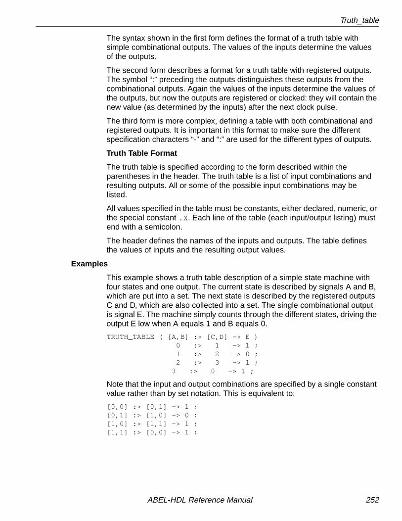
Truth_table
The syntax shown in the first form defines the format of a truth table withsimple combinational outputs. The values of the inputs determine the valuesof the outputs.
The second form describes a format for a truth table with registered outputs.The symbol “:” preceding the outputs distinguishes these outputs from thecombinational outputs. Again the values of the inputs determine the values ofthe outputs, but now the outputs are registered or clocked: they will contain thenew value (as determined by the inputs) after the next clock pulse.
The third form is more complex, defining a table with both combinational andregistered outputs. It is important in this format to make sure the differentspecification characters “-” and “:” are used for the different types of outputs.
Truth Table Format
The truth table is specified according to the form described within theparentheses in the header. The truth table is a list of input combinations andresulting outputs. All or some of the possible input combinations may belisted.
All values specified in the table must be constants, either declared, numeric, orthe special constant .X . Each line of the table (each input/output listing) mustend with a semicolon.
The header defines the names of the inputs and outputs. The table definesthe values of inputs and the resulting output values.
Examples
This example shows a truth table description of a simple state machine withfour states and one output. The current state is described by signals A and B,which are put into a set. The next state is described by the registered outputsC and D, which are also collected into a set. The single combinational outputis signal E. The machine simply counts through the different states, driving theoutput E low when A equals 1 and B equals 0.
TRUTH_TABLE ( [A,B] :> [C,D] -> E ) 0 :> 1 -> 1 ; 1 :> 2 -> 0 ; 2 :> 3 -> 1 ; 3 :> 0 -> 1 ;
Note that the input and output combinations are specified by a single constantvalue rather than by set notation. This is equivalent to:
[0,0] :> [0,1] -> 1 ;[0,1] :> [1,0] -> 0 ;[1,0] :> [1,1] -> 1 ;[1,1] :> [0,0] -> 1 ;
ABEL-HDL Reference Manual 252

Truth_table
When writing truth tables in ABEL-HDL (particularly when describingregistered circuits), follow the same rules for dot extensions, attributes, andpin-to-pin/detailed descriptions described earlier for writing equations. Theonly difference between equations and truth tables is the ordering of the inputsand outputs.
The following two fragments of source code, for example, are functionallyequivalent:
Fragment 1:
equations q := a & load # !q.fb & !load;
Fragment 2:
truth_table ( [a ,q.fb,load] :> q) [0 , 0 , 0 ] :> 1; [0 , 1 , 0 ] :> 0; [1 , 0 , 0 ] :> 1; [1 , 1 , 0 ] :> 0; [0 , 0 , 1 ] :> 0; [1 , 0 , 1 ] :> 1; [0 , 1 , 1 ] :> 0; [1 , 1 , 1 ] :> 1;
As an example, the following truth table defines an exclusive-OR function withtwo inputs (A and B), one enable (en), and one output (C):
TRUTH_TABLE ( [en, A , B ] -> C ) [ 0,.X.,.X.] -> .X.;" don't care w/enab off [ 1, 0 , 0 ] -> 0 ; [ 1, 0 , 1 ] -> 1 ; [ 1, 1 , 0 ] -> 1 ; [ 1, 1 , 1 ] -> 0 ;
See Als o ___________________________________________________________
ABEL-HDL Reference Manual 253

Wait
WaitSyntax
WAIT < integer >;
Use
This keyword presents the relative time delay which effects the test vectorsdirectly following the WAIT statement. It can be used in the MACRO block onlywhen this Macro is used in the Test_vectors block. The default time unit isnano-second.
Example 1
TEST_VECTORS ([A,B]->[C])[0,0]->.X.;WAIT 20;[1,1]->.X.;
Signal A keeps 0 for 20ns, then changes to 1.
Example 2
TEST_VECTORS ([A,B]->[C])[0,0]->.X.;[1,1]->.X.;WAIT 20; [0,0]->.X.;
Signal A appears 0 and changes to 1 at 0ns, then keeps 1 until it changes to 0at 20ns.
Example 3
TEST_VECTORS ([A,B]->[C][0,0]->.X.;[1,1]->.X.;[0,0]->.X.;
WAIT is not used in this example, the time interval is adjusted by the step sizespecified in the Setup Simulator dialog box which can be accessed bySimulate ⇒ Settings from the Simulator Control Panel. The default step sizeis 1000*100ps. So signal A keeps 0 for 1000*100ps and changes to 1, thenchanges to 0 after another 1000*100ps.
See Also ___________________________________________________________
Test_vectorsCycleflicker.abl
ABEL-HDL Reference Manual 254

When-Then-Else
When-Then-ElseSyntax
[ WHEN condition THEN ] [ ! ] element =expression ;[ ELSE equation ];
or[ WHEN condition THEN ] equation; [ ELSE equation ];
Purpose
The WHEN-THEN-ELSE statement is used in equations to describe a logicfunction.
Use
Equations use the “Assignment Operators” = and ?= (combinational), and:= and ?:= (registered) described in Chapter 1, “Language Structure.”
The complement operator, “!”, expresses negative logic. The complementoperator precedes the signal name and implies that the expression on the rightof the equation is to be complemented before it is assigned to the signal.Using the complement operator on the left side of equations is also supported;equations for negative logic parts can just as easily be expressed bycomplementing the expression on the right side of the equation.
condition Any valid expression.
element An identifier naming a signal or set of signals, or anactual set, to which the value of the expression isassigned.
expression Any valid expression.
=, :=, ?= and ?:= Combinational and registered (pin-to-pin)assignment operators.
▲ CAUTION WHEN-THEN-ELSE is only supported in equations. UseIF-THEN-ELSE in STATE_DIAGRAM descriptions.
✍ NOTE Equation blocks in conditional expressions such asWHEN-THEN result in logic functions that are logically ANDedwith the conditional expression that is in effect.
ABEL-HDL Reference Manual 255

When-Then-Else
Examples
WHEN (Mode == S_Data) THEN { Out_data := S_in; S_Valid := 1; }ELSE WHEN (Mode == T_Data) THEN { Out_data := T_in; T_Valid := 1; }
See Also ___________________________________________________________
“Equations” in Chapter 1, Language Structure”
ABEL-HDL Reference Manual 256
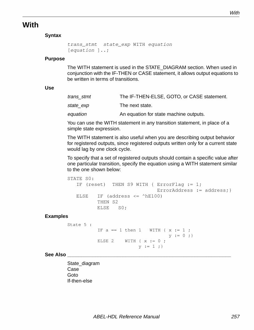
With
WithSyntax
trans_stmt state_exp WITH equation[ equation ]..;
Purpose
The WITH statement is used in the STATE_DIAGRAM section. When used inconjunction with the IF-THEN or CASE statement, it allows output equations tobe written in terms of transitions.
Use
trans_stmt The IF-THEN-ELSE, GOTO, or CASE statement.
state_exp The next state.
equation An equation for state machine outputs.
You can use the WITH statement in any transition statement, in place of asimple state expression.
The WITH statement is also useful when you are describing output behaviorfor registered outputs, since registered outputs written only for a current statewould lag by one clock cycle.
To specify that a set of registered outputs should contain a specific value afterone particular transition, specify the equation using a WITH statement similarto the one shown below:
STATE S0: IF (reset) THEN S9 WITH { ErrorFlag := 1; ErrorAddress := address;} ELSE IF (address <= ^hE100) THEN S2 ELSE S0;
Examples
State 5 : IF a == 1 then 1 WITH { x := 1 ; y := 0 ;} ELSE 2 WITH { x := 0 ; y := 1 ;}
See Also ___________________________________________________________
State_diagramCaseGotoIf-then-else
ABEL-HDL Reference Manual 257

XOR_factors
XOR_factorsSyntax
XOR_factorssignal name = xor_factors ;
Purpose
Use XOR_FACTORS to specify a Boolean expression to be factored out of(and XORed with) the sum-of-products reduced equations. Factors candramatically reduce the reduced equations if you use a device featuring XORgates.
Use
XOR_FACTORS converts a sum of products (SOP) equation into an exclusiveOR (XOR) equation. The resulting equation contains the sum of productfunctions that, when exclusive ORed together, have the same function as theoriginal. The XOR_FACTORS equation is divided into the original equation,with the factor (or its complement) on one side of the XOR and the remainderon the other.
After deciding the best xor_factors, remember to revise the source file touse an XOR device for the final design.
Examples
!Q16 = A & B & !D # A & B & !C # !B & C & D # !A & C & D;
Reordering the product terms indicates that (A & B) and (C & D) are goodcandidate factors, as shown below:
!Q16 = A & B & (!C # !D) # (!A # !B) & C & D;
✍ NOTE The assignment operator you use in XOR_FACTORSequations must match the assignment operator in theEQUATIONS section.
ABEL-HDL Reference Manual 258

XOR_factors
If we process the following source file, the program reduces the equationsaccording to the XOR_Factors, A & B.
module xorfact xorfact device 'P20X10'; Clk,OE pin 1,13; A,B,C,D pin 2,3,4,5; Q16 pin 16 istype 'reg,xor';XOR_Factors Q16 := A & B;equations !Q16 := A & B & !D # !B & C & D # !A & C & D # A & B & !C;end
Using A & B as the XOR_Factors, the reduced equations are
!Q16 := ((A & B) $ (C & D));
Example 2
The example octalf.abl uses a more complex high-level equation:
module OCTALFtitle 'Octal counter with xor factoring.'
octalf device 'P20X8'; D0..D7 pin 3..10; Q7..Q0 pin 15..22 istype 'reg,xor'; CLK,I0,I1,OC,CarryIn pin 1,2,11,13,23; CarryOut pin 14 istype 'com'; H,L,X,Z,C = 1, 0, .X., .Z., .C.;
Data = [D7..D0]; Count = [Q7..Q0];
Mode = [I1,I0]; Clear = [ 0, 0]; Hold = [ 0, 1]; Load = [ 1, 0]; Inc = [ 1, 1];
xor_factor Count.FB := Count & I0;
" ..comments removed..
ABEL-HDL Reference Manual 259
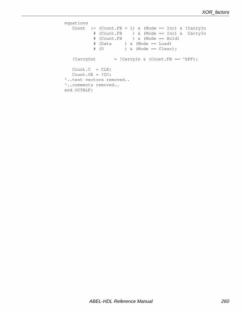
XOR_factors
equations Count := (Count.FB + 1) & (Mode == Inc) & !CarryIn # (Count.FB ) & (Mode == Inc) & CarryIn # (Count.FB ) & (Mode == Hold) # (Data ) & (Mode == Load) # (0 ) & (Mode == Clear);
!CarryOut = !CarryIn & (Count.FB == ^hFF);
Count.C = CLK; Count.OE = !OC;"..test vectors removed.."..comments removed..end OCTALF;
ABEL-HDL Reference Manual 260

Index
Symbols.ALCR 159.AP 159.AR 159.ASET 159.C. 19.CE 159.CLK 159.CLR 159.COM 79, 159.constant 19.D 79, 159
example 168.D. 19.ext
dot extension 158.F. 19.FB 79, 159.FC 159.J 159.K 159.K. 19.LD 159.LE 159.LH 159.OE 159
example 168.P. 19.PIN 79, 80, 159
assignment 235istype 222pin keyword 235using the range operator in 235
.PR 159example 168
.Q 79, 159
.R 159
.RE 159example 168
.S 160
.SET 160
.SP 160
.SR 160
.SVn. 19
.T 160
.U. 19
.X. 19
.Z. 19@Alternate
directive 174disabling 197
@Carrydirective 175
@Constdirective 176
@Dcsetdirective 177disabling 192example 85overrides dc, net, and pos 225precautions 84with state machines 94
@Dcstatedirective 178
@Directive 173@Exit
directive 179@Expr
directive 180@If
directive 181@Ifb
directive 182@Ifdef 183@Ifiden 184@Ifnb 185@Ifndef 186@Ifniden 187@Include 188@Irp 189@Irpc 190@Message 191@Onset 192@Page 193@Radix 194@Repeat 195
ABEL-HDL Reference Manual 261

Index
@Setsize 196@Standard 197^b 22^d 22^h 22^o 22
Numerics12-to-4 multiplexer, example 1143-state outputs 623-state sequencer, example 1314-bit comparator, example 1254-bit universal counter, example 1187-segment display decoder, example 128
AABEL-HDL
introduction to 15structure 43syntax 15
Active levels for devices 76Active-low declarations 74actlow1.abl 75actlow2.abl 74Addition 25Alternate flip-flop types 72Ambiguities 67AND
alternate operator for 174Architecture independence
attributes 65dot extensions 66dot extensions, example 80resolving ambiguities 67
Argumentsdefining in module statement 232
Arithmetic operators 25ASCII, supported characters 16Assignment operators 28Assignments
device 204multiple, to same identifier 32node 233pin 235
Async_resetkeyword 198
Asynchronous preset 158Attribute and polarity control 77Attributes
’buffer’ 224’collapse’ 224’com’ 224
’dc’ 225’invert’ 224’keep’ 224’neg’ 225’pos’ 225’reg_d’ 225’reg_g’ 225’reg_jk’ 226’reg_sr’ 226’reg_t’ 226’reg’ 225’retain’ 226’xor’ 226architecture independence 65collapsing nodes 64in lower-level sources 62inherited by higher-level sources 208istype 222
B^b 22Base numbers
binary, octal, hexadecimal, decimal 22changing 194
bcd7.abl 130Bidirectional 3-state buffer, example 122Binary 22binbcd.abl 140bjack.abl 146Blackjack machine 134Blocks 19Buffer 224
and polarity control 77example 70
Buried nodes, declaring 233
CCase
keyword 199Chained if-then-else 215Clock enable 159Clocked memory element
istype reg 225Clocked memory element, Istype ’reg’ 225Closing a module 205Collapse
attribute 224Collapsing combinational nodes
istype ’collapse’ 224istype ’keep’ 224
Collapsing nodes 64selective 65
ABEL-HDL Reference Manual 262

Index
Comattribute 224
Combinational nodes 62Combinatorial device, attribute for 224Comments 21comp4a.abl 127Complement operator 31Constants
declarations 169declared in macros 176intermediate expressions 170
Counterexample 118
counter.abl 209
D^d 22D flip-flop
clocked memory element 225dot extensions 161gated clocked memory element 225unsatisfied transition condition 92
Dangling nodes 62Dc 225
attribute 225dc.abl 85Dc-set 84
and optimization 85Decimal 22Declarations
active-low 74constants 169device 204fuses 211keyword 203macro 228node 233pin 235signal 50structure 46
Declared equations vs. macros 228decode.abl 114Default values
for lower-level source signals 217supported values 221
Design considerations 60Detail descriptions
designing for macrocells 68example, dot extensions 83example, inverting 70example, non-inverting 70when to use 72
detail1.abl 82detail2.abl 83Device
keyword 204Device kits, passing information to 237Devices
@radix 194changing base numbering system 194declaring fuse states 211programmable polarity 76
Directives@alternate 174@carry 175@const 176@dcset 177@dcstate 178@exit 179@expr 180@if 181@ifb 182@ifdef 183@ifiden 184@ifnb 185@ifndef 186@ifniden 187@include 188@irp 189@irpc 190@message 191@onset 192@page 193@repeat 195@setsize 196@standard 197if blank 182if defined 183if identical 184if not blank 185if not defined 186if not identical 187
Division 25Don’t cares
@dcset 177Dot extension example
detail 83Dot extensions 158
.COM 79
.D 79
.ext 158
.FB 79
.PIN 79
.Q 79
ABEL-HDL Reference Manual 263

Index
and architecture independence,example 80
and detail descriptions 82and feedback 79drawings of 167example, detail 82for flip-flop types 161no 79not allowed across sources 217pin-to-pin 163
Dummy argumentsdefining in module statement 232
EElse
keyword 214Emulation of flip-flop 87End
keyword 205Endcase 199Equation polarity 77Equations
keyword 206overview 31when-then-else 206, 255XORs 86
Equations for flip-flops 78Equations of XORs 86Examples
12-to-4 multiplexer using equations 1143-state sequencer, state machine 1314-bit comparator, equations 1254-bit universal counter 1185-bit adder 1347-segment display decoder, truth
tables 128adder 134bidirectional 3-state buffer, equations 122binary to BCD converter 134blackjack machine, state machine 134memory address decoder, equations 112multiplexer 134
Expressions 29directive for 180
FFactors, XOR 258Feedback
and dot extensions 79merging 64referencing across sources 217
Filesincluding in source file 227
Files, including in source file 188Flip-flops 93
and dot extensions 78, 79detail descriptions 72D-type 92emulations with XORs 87state diagrams 73using for alternative flip-flop types 72
Form feed 193Functional_block
keyword 208Fuses
keyword 211
GGated clock D flip-flop, dot extensions 161Goto
keyword 213Greater than 25
H^h 22Header 46, 249Hexadecimal 22Hierarchy 61Hierarchy declarations
creating multiple instances of asource 208
functional_block 208inheriting attributes 208interface (lower-level) 219interface (top-level source) 217overriding default values 210supported default values 221unlisted pins 221unused outputs 210wiring lower-level signals 209
IIdentifiers 16
choosing 18in state machines 90multiple assignments to 32reserved 18
If blank 182If defined 183If identical 184If not blank 185If not defined 186If not identical 187
ABEL-HDL Reference Manual 264

Index
If-then-elsekeyword 214
Illegal state in state machines 93Include files 227Indefinite repeat 189
character 190Input pin 235Instantiation 61
interface (lower-level) 219interface (top-level) 217of lower-level source 61, 208
Interface (lower-level)keyword 219
Interface (top-level)keyword 217
Interface, submodule 61Intermediate expressions 170Invert
attribute 224example 70
Inverterpolarity control 77
Inverting outputs, attribute for 224Istype and polarity control 77Istype, keyword 222
JJK flip-flop
clocked memory element 226dot extensions 161emulation of 88
JK flip-flops 73
KKeep
attribute 224Keywords
async_reset 198case 199declarations 203device 204end 205equations 206functional_block 208fuses 211goto 213if-then-else 214interface (lower-level source) 219interface (top-level source) 217istype 222library 227macro 228
module 232node 233pin 235property 237state (declaration) 238state (in state_diagram) 239state_diagram 240state_register 245sync_reset 198test_vectors 247title 249trace 250truth_table 251when-then-else 255with 257XOR_factors 258
LLatch-enable 158Less than 26Library
keyword 227Linking modules 64
merging feedbacks 64post-linked optimization 64
Logic descriptions 53Lower-level sources 61
instantiating 208L-type latch, dot extensions 161
Mmac.abl 229Macro
keyword 228keyword example 229
Macrosvs. declared equations 228
Memory address decoderexample 112
Merging feedbacks 64Minus 25Module
beginning 232defined 46ending 205keyword 232
Modulus 25Multiplication 25mux12t4.abl 117muxadd.abl 138
ABEL-HDL Reference Manual 265

Index
NNeg 225
attribute 225No connects, in hierarchy declarations 210No dot extension 79Node
collapsing 64combinational 62dangling 62istype 222keyword 233registered 62removing redundant 63selective collapsing 65using the range operator in 233
Non-inverting outputsattribute for 224
NOT 25alternate operator for 174
Numbers 22changing base 194
O^o 22Octal 22octalf.abl 259Off-set 84One-bit changes 98On-set 84Operators
alternate set of 174arithmetic 25assignment 28complement 31logic 25overview 24priority 29, 30relational 26standard set 197
Optimizationand @dcset 88of XORs 86post-linked 64reducing product terms 98
Optimization and @dcset 85Optimization of XORs 86OR 25
alternate operator for 174Other flip-flops 93Output enables 62Output pin 235Outputs, using istype for 222
PPin
assignments 235istype 222keyword 235using the range operator in 235
pin2pin.abl 81Pin-to-pin descriptions 66, 67
example 69Pin-to-pin descriptions and flip-flops 78Plus 25Polarity control 76, 77
active levels 76, 77istype 77
Ports, declaring lower-level 61, 63Pos
attribute 225Post-linked optimization 64Powerup register states 92Powerup state 92Preset
built-in, example 71Priority of operators 29Product terms
reducing 98reducing with intermediate
expressions 170Programmable polarity, active levels for
devices 76Property
keyword 237
QQ11.abl 69Q12.abl 70Q13.abl 70Q15.abl 71Q17.abl 72
RRange operators
example 119in hierarchy declarations 208in node declarations 233in pin declarations 235using 119
Reduction, XOR_factors 258Redundant nodes 63Redundant product terms, retaining 226Reg
attribute 225
ABEL-HDL Reference Manual 266

Index
Reg_dattribute 225
Reg_gattribute 225
Reg_jk 226attribute 226
Reg_srattribute 226
Reg_tattribute 226
Register load input 159Registered design descriptions 66Registered nodes 62Registers
bit values in state machines 99cleared state in state machines 93dot extensions 158, 161powerup states 92
Relational operators 26Repeat
@irp directive 189@irpc directive 190
Resetexample, inverted architecture 72example, non-inverted architecture 71resolving ambiguities 71
Retainattribute 226
SSelective collapsing 65sequence.abl 91, 133Set 37Set operations 34Sets 33, 118
assignment and comparison 35evaluation of 37indexing 33limitations 39using to create modes 118
Shift 25Signals
nodes 233pin 235
Simulationtest_vectors 247trace keyword 250
Source filesbeginning 232declarations 46design considerations 60directives 59
header 46logic descriptions 53structure of 43test vectors 58
Special constants 19SR flip-flop 73
clocked memory element 226dot extensions 161
Statedeclarations 238in descriptions 239keyword 238
State (in State_diagram)keyword 239
State machine example 91, 243@dcset 963-state sequencer 131blackjack machine 134no @dcset 94
State machinesand @dcset 86, 94case keyword 199cleared register state 93design considerations 90goto 213identifiers in 90identifying states 99if-then-else 214illegal states 93powerup register states 92reducing product terms 98state (in state_diagram) 239state_diagram 240test vectors for 248transition statements 241using state register outputs 99with 257
State registers 99State_diagram
keyword 240State_diagram, @dcstate 178State_register
keyword 245statema.abl 243Subtraction 25Sum-of-products, XOR_factors 258Symbolic state descriptions 99
specifying reset logic 198Sync_reset
keyword 198Synchronous preset 160Syntax 15
ABEL-HDL Reference Manual 267

Index
TT flip-flop
and equations 78clocked memory element 226dot extensions 161
Tabular truth table 251Test vectors
test_vectors keyword 247trace keyword 250
Test_vectorskeyword 247
Thenkeyword 214
Times 25Title
keyword 249Trace
keyword 250traffic.abl 94traffic1.abl 96Transferring designs 65Transition conditions 92Transition statements 241Transitions
case keyword 199if-then-else keyword 214
Truth tables7-segment display decoder example 128truth_table keyword 251
Truth_tablekeyword 251
tsbuffer.abl 124
Uunicnt.abl 118Unlisted pins
in hierarchy declarations 221Unspecified logic values
istype dc|pos|neg 225
WWhen-then-else 206
keyword 255With
keyword 257
Xx1.abl 86x2.abl 87XNOR
alternate operator for 174
XORalternate operator for 174attribute for 226
XOR_Factorsexample 259summary 57
XOR_factorskeyword 258
xorfact.abl 259XORs
and operator priority 87equations 86example 86, 87flip-flop emulation 87implied in equations 87optimization of 86
ABEL-HDL Reference Manual 268