abel-hdl primer - eelinux.ee.usm.maine.edueelinux.ee.usm.maine.edu/courses/ele172/abel/hdl-abel...
TRANSCRIPT
HDL-ABEL Primer
1 of 21 4/10/2008 8:44 AM
ABEL-HDL PrimerABEL Primer Contents
1. Introduction2. Basic structure of an ABEL source file3. Declarations (module, pin, node, constants)4. Numbers5. Directives6. Sets
a. Indexing or accessing a setb. Set operations
6. Operatorsa. Logical Operatorsb. Arithmetic operatorsc. Relational operatorsd. Assignment operatorse. Operator priority
8. Logic descriptiona. Equations
When-Then-Else statementb. Truth Tablec. State Description
State_diagramIf-Then-Else statementWith statementCase statement
d. Dot extensions9. Test vectors10. Device Specific (Property) Statements11. Miscellaneous
a. Active-low declarations12. Examples
Moore Finite State MachineMealy Finite State MachineSynchronous Mealy Finite State Machine
Common MistakesReferencesAcknowledgement
1 Introduction
ABEL (Advanced Boolean Equation Language) allows you to enter behavior-like descriptions of a logic circuit.ABEL is an industry-standard hardware description language (HDL) that was developed by Data I/OCorporation for programmable logic devices (PLD). There are other hardware description languages such asVHDL and Verilog. ABEL is a simpler language than VHDL which is capable of describing systems of largercomplexity.
ABEL can be used to describe the behavior of a system in a variety of forms, including logic equations, truth
HDL-ABEL Primer
2 of 21 4/10/2008 8:44 AM
tables, and state diagrams using C-like statements. The ABEL compiler allows designs to be simulated andimplemented into PLDs such as PALs, CPLDs and FPGAs.
Following is a brief overview of some of the features and syntax of ABEL. It is not intended to be a completediscussion of all its features. This ABEL primer will get you started with writing ABEL code. In case you arefamiliar with ABEL, this write-up can serve as a quick reference of the most often used commands. For moreadvanced features, please consult an ABEL manual or the Xilinx on-line documentation.
2. Basic structure of an ABEL source file
An ABEL source file consists of the following elements.
Header: including Module, Options and TitleDeclarations: Pin, Constant, Node, Sets, States. Library.Logic Descriptions: Equations, Truth-table, State_diagramTest Vectors: Test_vectorsEnd
Keywords (words recognized by ABEL such as commands, e.g. goto, if, then, module, etc.) are not casesensitive. User-supplied names and labels (identifier) can be uppercase, lowercase or mixed-case, but are case-sensitive (input1 is different from Input1).
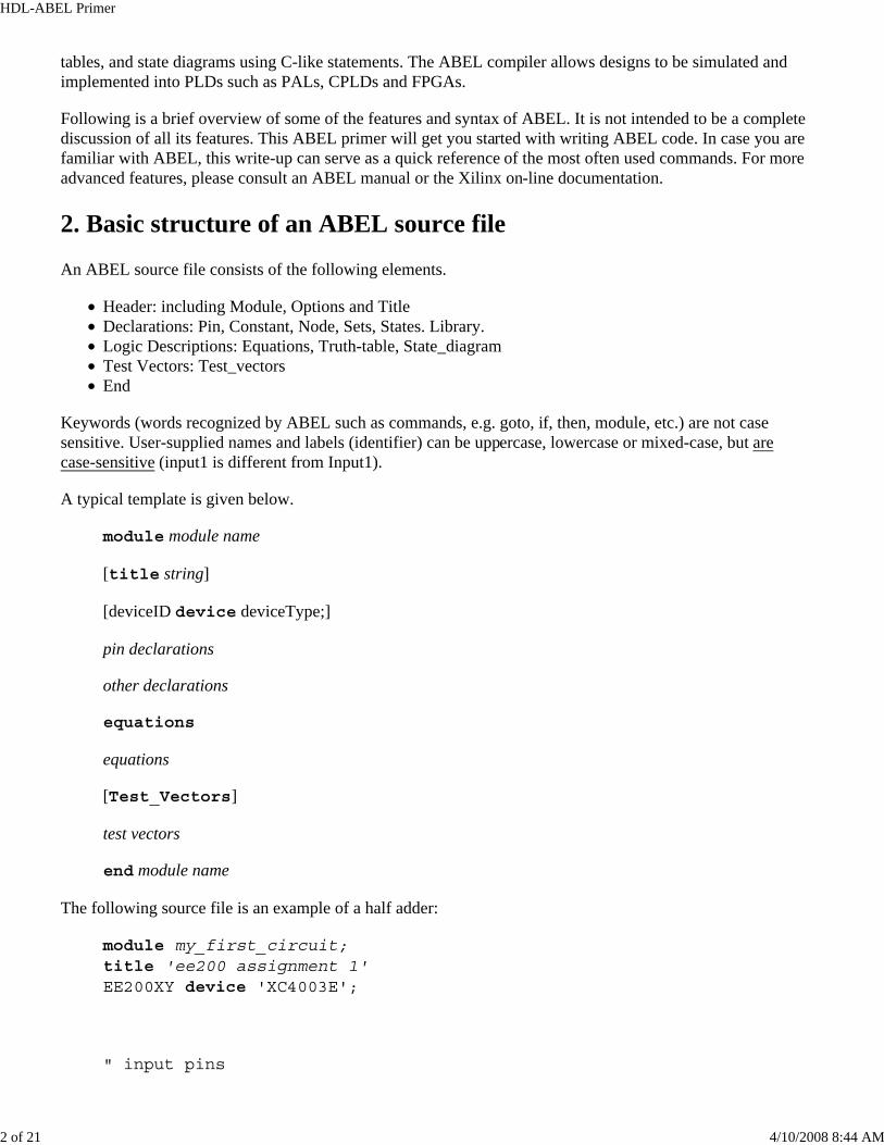
A typical template is given below.
module module name
[title string]
[deviceID device deviceType;]
pin declarations
other declarations
equations
equations
[Test_Vectors]
test vectors
end module name
The following source file is an example of a half adder:
module my_first_circuit; title 'ee200 assignment 1' EE200XY device 'XC4003E';
" input pins
HDL-ABEL Primer
3 of 21 4/10/2008 8:44 AM
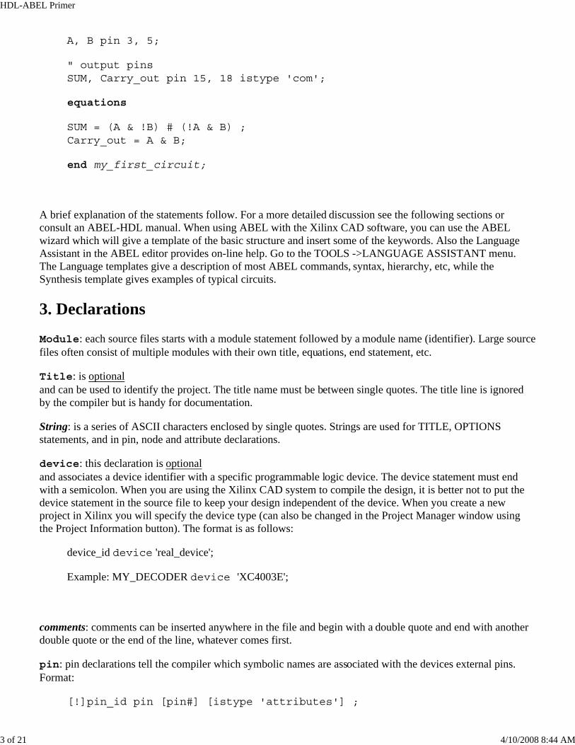
A, B pin 3, 5;
" output pins SUM, Carry_out pin 15, 18 istype 'com';
equations
SUM = (A & !B) # (!A & B) ; Carry_out = A & B;
end my_first_circuit;
A brief explanation of the statements follow. For a more detailed discussion see the following sections orconsult an ABEL-HDL manual. When using ABEL with the Xilinx CAD software, you can use the ABELwizard which will give a template of the basic structure and insert some of the keywords. Also the LanguageAssistant in the ABEL editor provides on-line help. Go to the TOOLS ->LANGUAGE ASSISTANT menu.The Language templates give a description of most ABEL commands, syntax, hierarchy, etc, while theSynthesis template gives examples of typical circuits.
3. Declarations
Module: each source files starts with a module statement followed by a module name (identifier). Large sourcefiles often consist of multiple modules with their own title, equations, end statement, etc.
Title: is optionaland can be used to identify the project. The title name must be between single quotes. The title line is ignoredby the compiler but is handy for documentation.
String: is a series of ASCII characters enclosed by single quotes. Strings are used for TITLE, OPTIONSstatements, and in pin, node and attribute declarations.
device: this declaration is optionaland associates a device identifier with a specific programmable logic device. The device statement must endwith a semicolon. When you are using the Xilinx CAD system to compile the design, it is better not to put thedevice statement in the source file to keep your design independent of the device. When you create a newproject in Xilinx you will specify the device type (can also be changed in the Project Manager window usingthe Project Information button). The format is as follows:
device_id device 'real_device';
Example: MY_DECODER device 'XC4003E';
comments: comments can be inserted anywhere in the file and begin with a double quote and end with anotherdouble quote or the end of the line, whatever comes first.
pin: pin declarations tell the compiler which symbolic names are associated with the devices external pins.Format:
[!]pin_id pin [pin#] [istype 'attributes'] ;
HDL-ABEL Primer
4 of 21 4/10/2008 8:44 AM
One can specify more than one pin per line:
[!]pin_id , pin_id, pin_id pin [pin#, [pin#, [pin#]]] [istype 'attributes'];
Example:
IN1, IN2, A1 pin 2, 3, 4;
OUT1 pin 9 istype 'reg';
ENABLE pin;
!Chip_select pin 12 istype 'com';
!S0..!S6 pin istype 'com';
You do not need to specify the pin. Pin numbers can be specified later by using a "user constraint file " whendoing the compilation using Xilinx CAD. This has the advantage that our design is more general and flexible.The ! indicates an active low (the signal will be inverted). The istype is an optional attribute assignment fora pin such as 'com' to indicate that the output is a combinational signal or 'reg' for a clocked signal (registeredwith a flip flop). This attribute is only for output pins.
node: node declarations have the same format as the pin declaration. Nodes are internal signals which are notconnected to external pins.
Example:
tmp1 node [istype 'com'];
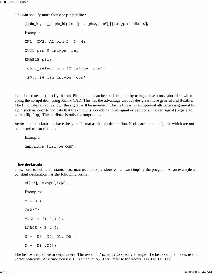
other declarationsallows one to define constants, sets, macros and expressions which can simplify the program. As an example aconstant declaration has the following format:
id [, id],... = expr [, expr].. ;
Examples:
A = 21;
C=2*7;
ADDR = [1,0,11];
LARGE = B & C;
D = [D3, D2, D1, D0];
D = [D3..D0];
The last two equations are equivalent. The use of ".." is handy to specify a range. The last example makes use ofvector notations. Any time you use D in an equation, it will refer to the vector [D3, D2, D1. D0].
HDL-ABEL Primer
5 of 21 4/10/2008 8:44 AM
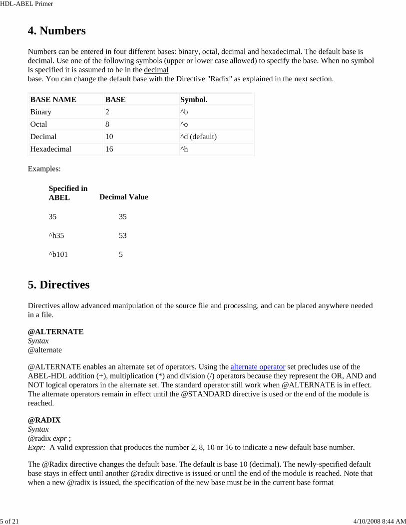
4. Numbers
Numbers can be entered in four different bases: binary, octal, decimal and hexadecimal. The default base isdecimal. Use one of the following symbols (upper or lower case allowed) to specify the base. When no symbolis specified it is assumed to be in the decimalbase. You can change the default base with the Directive "Radix" as explained in the next section. BASE NAME BASE Symbol.Binary 2 ^b Octal 8 ^o Decimal 10 ^d (default) Hexadecimal 16 ^h
Examples:
Specified in ABEL Decimal Value
35 35
^h35 53
^b101 5
5. Directives
Directives allow advanced manipulation of the source file and processing, and can be placed anywhere neededin a file.
@ALTERNATE Syntax @alternate
@ALTERNATE enables an alternate set of operators. Using the alternate operator set precludes use of the ABEL-HDL addition (+), multiplication (*) and division (/) operators because they represent the OR, AND andNOT logical operators in the alternate set. The standard operator still work when @ALTERNATE is in effect.The alternate operators remain in effect until the @STANDARD directive is used or the end of the module isreached.
@RADIX Syntax @radix expr ; Expr: A valid expression that produces the number 2, 8, 10 or 16 to indicate a new default base number.
The @Radix directive changes the default base. The default is base 10 (decimal). The newly-specified defaultbase stays in effect until another @radix directive is issued or until the end of the module is reached. Note thatwhen a new @radix is issued, the specification of the new base must be in the current base format
HDL-ABEL Primer
6 of 21 4/10/2008 8:44 AM
Example
@radix 2; “change default base to binary … @radix 1010; “change back from binary to decimal
@STANDARD Syntax @standard
The @standard option resets the operators to the ABEL-HDL standard. The alternate set is chosen with the@alternative directive.
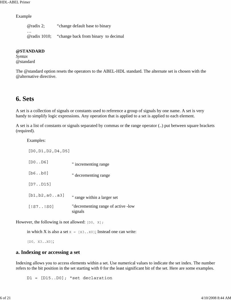
6. Sets
A set is a collection of signals or constants used to reference a group of signals by one name. A set is veryhandy to simplify logic expressions. Any operation that is applied to a set is applied to each element.
A set is a list of constants or signals separated by commas or the range operator (..) put between square brackets(required).
Examples:
[D0,D1,D2,D4,D5]
[D0..D6] " incrementing range
[b6..b0] " decrementing range
[D7..D15]
[b1,b2,a0..a3] " range within a larger set
[!S7..!S0] "decrementing range of active -low signals
However, the following is not allowed: [D0, X];
in which X is also a set X = [X3..X0]; Instead one can write:
[D0, X3..X0];
a. Indexing or accessing a set
Indexing allows you to access elements within a set. Use numerical values to indicate the set index. The numberrefers to the bit position in the set starting with 0 for the least significant bit of the set. Here are some examples.
D1 = [D15..D0]; "set declaration
HDL-ABEL Primer
7 of 21 4/10/2008 8:44 AM
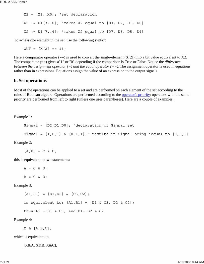
X2 = [X3..X0]; "set declaration
X2 := D1[3..0]; "makes X2 equal to [D3, D2, D1, D0]
X2 := D1[7..4]; "makes X2 equal to [D7, D6, D5, D4]
To access one element in the set, use the following syntax:
OUT = (X[2] == 1);
Here a comparator operator (==) is used to convert the single-element (X[2]) into a bit value equivalent to X2.The comparator (==) gives a"1" or "0" depending if the comparison is True or False. Notice the differencebetween the assignment operator (=) and the equal operator (==). The assignment operator is used in equationsrather than in expressions. Equations assign the value of an expression to the output signals.
b. Set operations
Most of the operations can be applied to a set and are performed on each element of the set according to therules of Boolean algebra. Operations are performed according to the operator's priority; operators with the samepriority are performed from left to right (unless one uses parentheses). Here are a couple of examples.
Example 1:
Signal = [D2,D1,D0]; "declaration of Signal set
Signal = [1,0,1] & [0,1,1];" results in Signal being "equal to [0,0,1]
Example 2:
[A,B] = C & D;
this is equivalent to two statements:
A = C & D;
B = C & D;
Example 3:
[A1,B1] = [D1,D2] & [C3,C2];
is equivalent to: [A1,B1] = [D1 & C3, D2 & C2];
thus A1 = D1 & C3, and B1= D2 & C2.
Example 4:
X & [A,B,C];
which is equivalent to
[X&A, X&B, X&C];
HDL-ABEL Primer
8 of 21 4/10/2008 8:44 AM
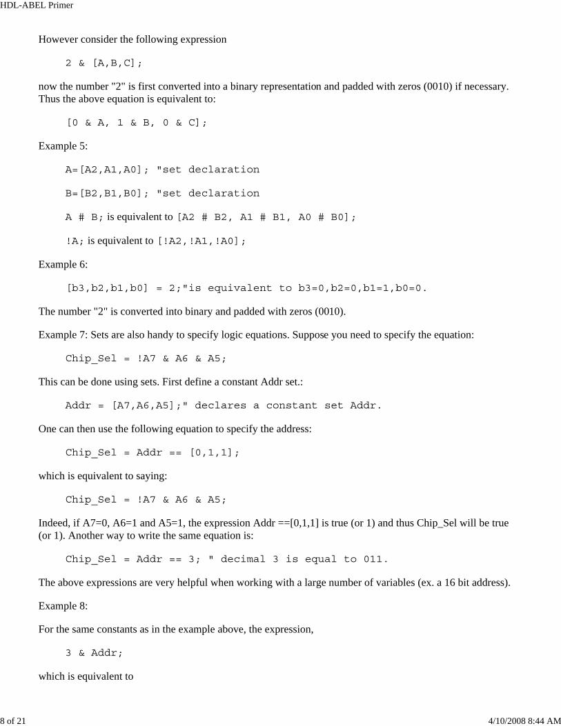
However consider the following expression
2 & [A,B,C];
now the number "2" is first converted into a binary representation and padded with zeros (0010) if necessary.Thus the above equation is equivalent to:
[0 & A, 1 & B, 0 & C];
Example 5:
A=[A2,A1,A0]; "set declaration
B=[B2,B1,B0]; "set declaration
A # B; is equivalent to [A2 # B2, A1 # B1, A0 # B0];
!A; is equivalent to [!A2,!A1,!A0];
Example 6:
[b3,b2,b1,b0] = 2;"is equivalent to b3=0,b2=0,b1=1,b0=0.
The number "2" is converted into binary and padded with zeros (0010).
Example 7: Sets are also handy to specify logic equations. Suppose you need to specify the equation:
Chip_Sel = !A7 & A6 & A5;
This can be done using sets. First define a constant Addr set.:
Addr = [A7,A6,A5];" declares a constant set Addr.
One can then use the following equation to specify the address:
Chip_Sel = Addr == [0,1,1];
which is equivalent to saying:
Chip_Sel = !A7 & A6 & A5;
Indeed, if A7=0, A6=1 and A5=1, the expression Addr ==[0,1,1] is true (or 1) and thus Chip_Sel will be true(or 1). Another way to write the same equation is:
Chip_Sel = Addr == 3; " decimal 3 is equal to 011.
The above expressions are very helpful when working with a large number of variables (ex. a 16 bit address).
Example 8:
For the same constants as in the example above, the expression,
3 & Addr;
which is equivalent to
HDL-ABEL Primer
9 of 21 4/10/2008 8:44 AM
[0,1,1] & [A7,A6,A5]
[0 & A7, 1 & A6, 1 & A5]
[0,A6,A5].
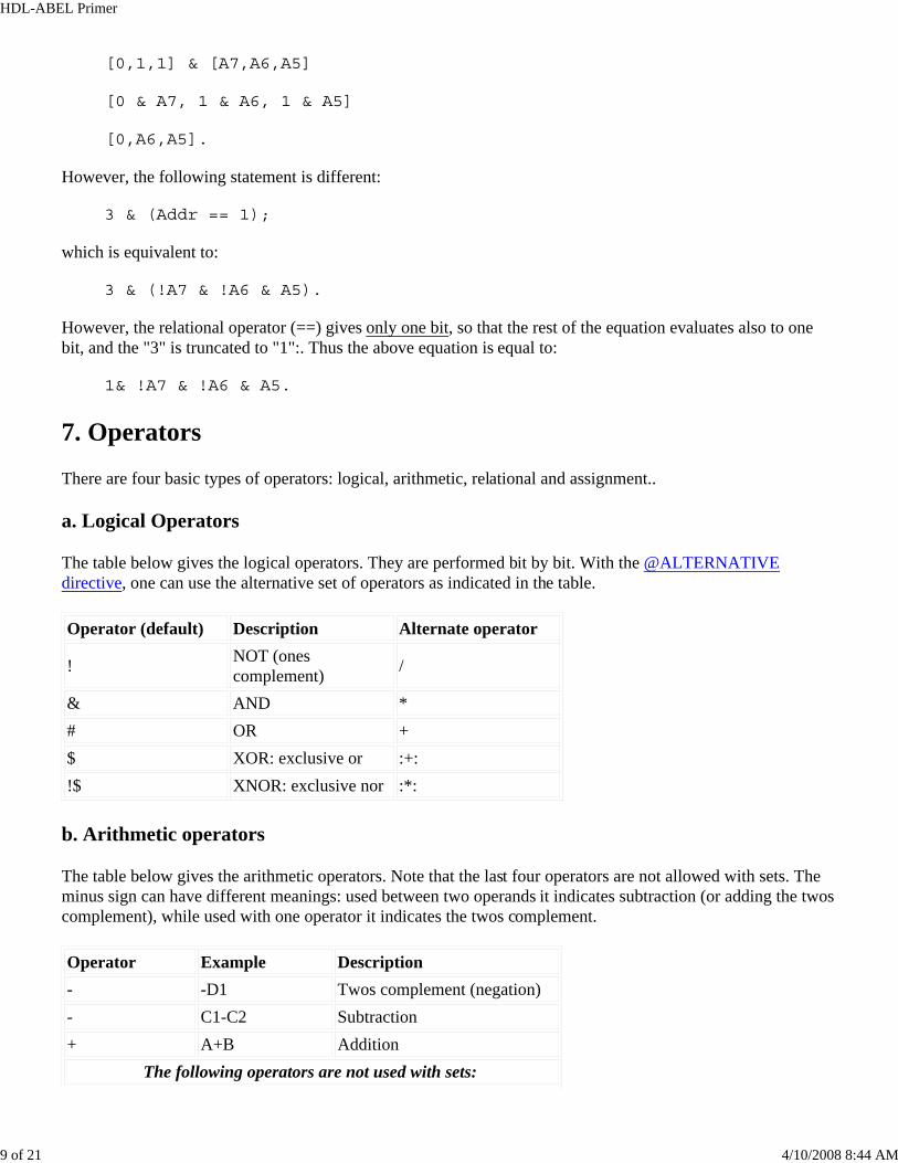
However, the following statement is different:
3 & (Addr == 1);
which is equivalent to:
3 & (!A7 & !A6 & A5).
However, the relational operator (==) gives only one bit, so that the rest of the equation evaluates also to onebit, and the "3" is truncated to "1":. Thus the above equation is equal to:
1& !A7 & !A6 & A5.
7. Operators
There are four basic types of operators: logical, arithmetic, relational and assignment..
a. Logical Operators
The table below gives the logical operators. They are performed bit by bit. With the @ALTERNATIVE directive, one can use the alternative set of operators as indicated in the table. Operator (default) Description Alternate operator
! NOT (ones complement) /
& AND * # OR +$ XOR: exclusive or :+: !$ XNOR: exclusive nor :*:
b. Arithmetic operators
The table below gives the arithmetic operators. Note that the last four operators are not allowed with sets. Theminus sign can have different meanings: used between two operands it indicates subtraction (or adding the twoscomplement), while used with one operator it indicates the twos complement. Operator Example Description- -D1 Twos complement (negation) - C1-C2 Subtraction + A+B Addition
The following operators are not used with sets:
HDL-ABEL Primer
10 of 21 4/10/2008 8:44 AM
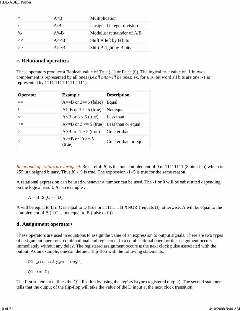
* A*B Multiplication / A/B Unsigned integer division % A%B Modulus: remainder of A/B << A<<B Shift A left by B bits >> A>>B Shift B right by B bits
c. Relational operators
These operators produce a Boolean value of True (-1) or False (0). The logical true value of -1 in twoscomplement is represented by all ones (i.e.all bits will be ones: ex. for a 16 bit word all bits are one: -1 isrepresented by 1111 1111 1111 1111). Operator Example Description == A==B or 3==5 (false) Equal!= A!=B or 3 != 5 (true) Not equal< A<B or 3 < 5 (true) Less than<= A<=B or 3 <= 5 (true) Less than or equal> A>B or -1 > 5 (true) Greater than
>= A>=B or !0 >= 5(true) Greater than or equal
Relational operators are unsigned. Be careful: !0 is the one complement of 0 or 11111111 (8 bits data) which is255 in unsigned binary. Thus !0 > 9 is true. The expression -1>5 is true for the same reason.
A relational expression can be used whenever a number can be used. The -1 or 0 will be substituted dependingon the logical result. As an example :
A = B !$ (C == D);
A will be equal to B if C is equal to D (true or 11111...; B XNOR 1 equals B), otherwise, A will be equal to thecomplement of B (if C is not equal to B (false or 0)).
d. Assignment operators
These operators are used in equations to assign the value of an expression to output signals. There are two typesof assignment operators: combinational and registered. In a combinational operator the assignment occursimmediately without any delay. The registered assignment occurs at the next clock pulse associated with theoutput. As an example, one can define a flip-flop with the following statements:
Q1 pin istype 'reg';
Q1 := D;
The first statement defines the Q1 flip-flop by using the 'reg' as istype (registered output). The second statementtells that the output of the flip-flop will take the value of the D input at the next clock transition.
HDL-ABEL Primer
11 of 21 4/10/2008 8:44 AM
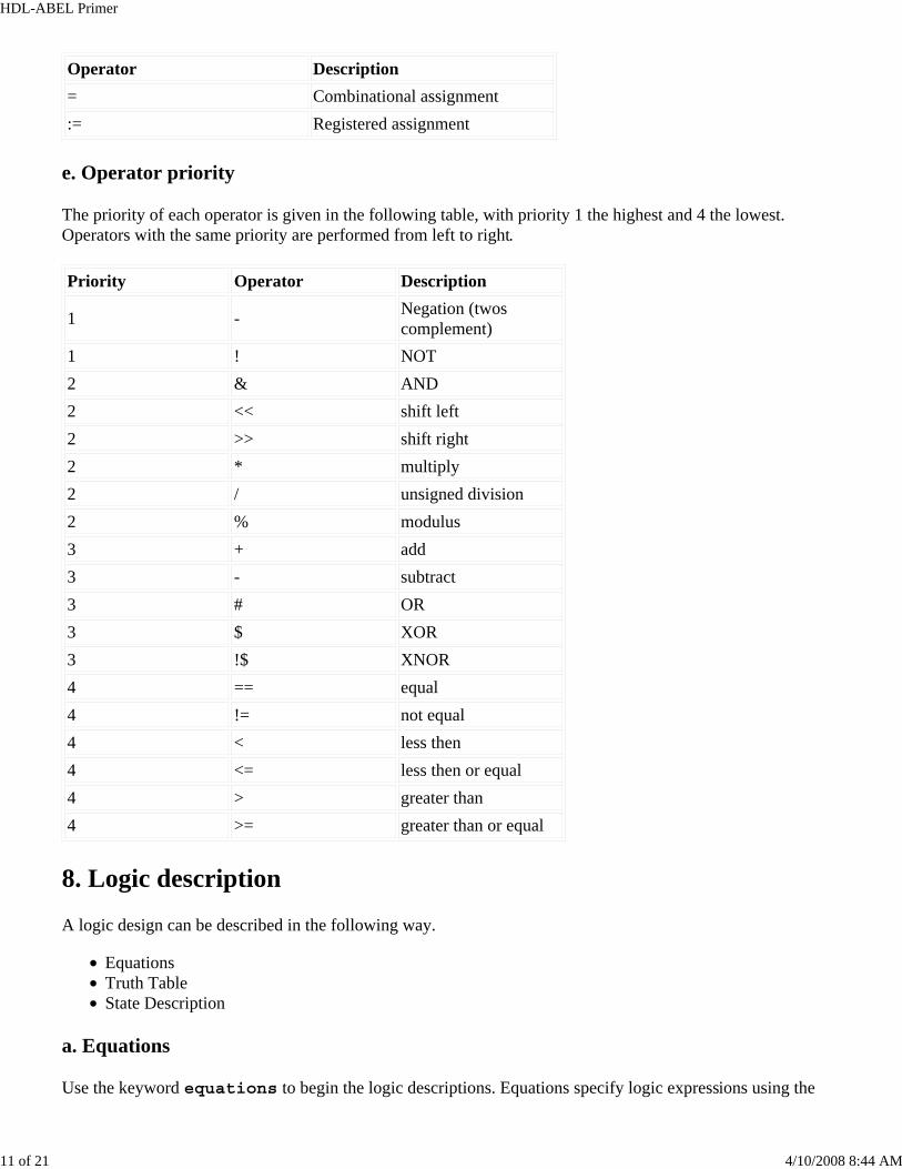
Operator Description= Combinational assignment := Registered assignment
e. Operator priority
The priority of each operator is given in the following table, with priority 1 the highest and 4 the lowest.Operators with the same priority are performed from left to right. Priority Operator Description
1 - Negation (twoscomplement)
1 ! NOT 2 & AND 2 << shift left 2 >> shift right 2 * multiply 2 / unsigned division 2 % modulus 3 + add 3 - subtract 3 # OR3 $ XOR 3 !$ XNOR 4 == equal 4 != not equal 4 < less then 4 <= less then or equal 4 > greater than 4 >= greater than or equal
8. Logic description
A logic design can be described in the following way.
EquationsTruth TableState Description
a. Equations
Use the keyword equations to begin the logic descriptions. Equations specify logic expressions using the
HDL-ABEL Primer
12 of 21 4/10/2008 8:44 AM
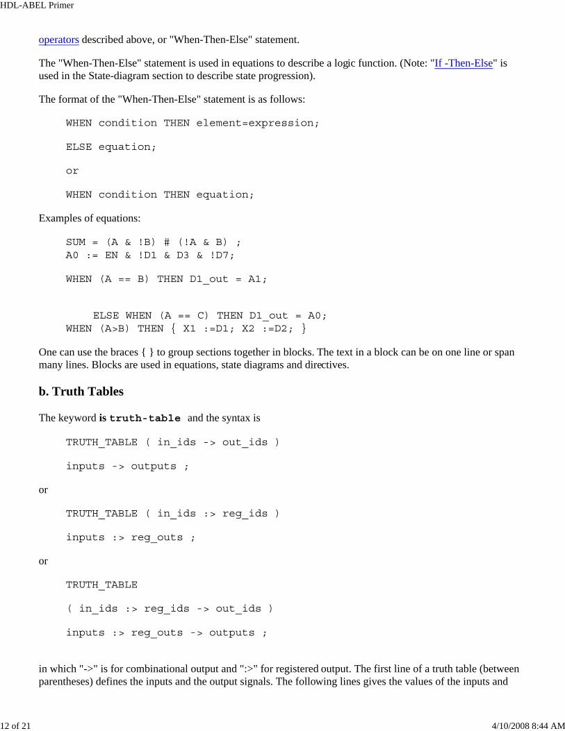
operators described above, or "When-Then-Else" statement.
The "When-Then-Else" statement is used in equations to describe a logic function. (Note: "If -Then-Else" is used in the State-diagram section to describe state progression).
The format of the "When-Then-Else" statement is as follows:
WHEN condition THEN element=expression;
ELSE equation;
or
WHEN condition THEN equation;
Examples of equations:
SUM = (A & !B) # (!A & B) ; A0 := EN & !D1 & D3 & !D7;
WHEN (A == B) THEN D1_out = A1;
ELSE WHEN (A == C) THEN D1_out = A0;
WHEN (A>B) THEN { X1 :=D1; X2 :=D2; }
One can use the braces { } to group sections together in blocks. The text in a block can be on one line or spanmany lines. Blocks are used in equations, state diagrams and directives.
b. Truth Tables
The keyword is truth-table and the syntax is
TRUTH_TABLE ( in_ids -> out_ids )
inputs -> outputs ;
or
TRUTH_TABLE ( in_ids :> reg_ids )
inputs :> reg_outs ;
or
TRUTH_TABLE
( in_ids :> reg_ids -> out_ids )
inputs :> reg_outs -> outputs ;
in which "->" is for combinational output and ":>" for registered output. The first line of a truth table (betweenparentheses) defines the inputs and the output signals. The following lines gives the values of the inputs and
HDL-ABEL Primer
13 of 21 4/10/2008 8:44 AM
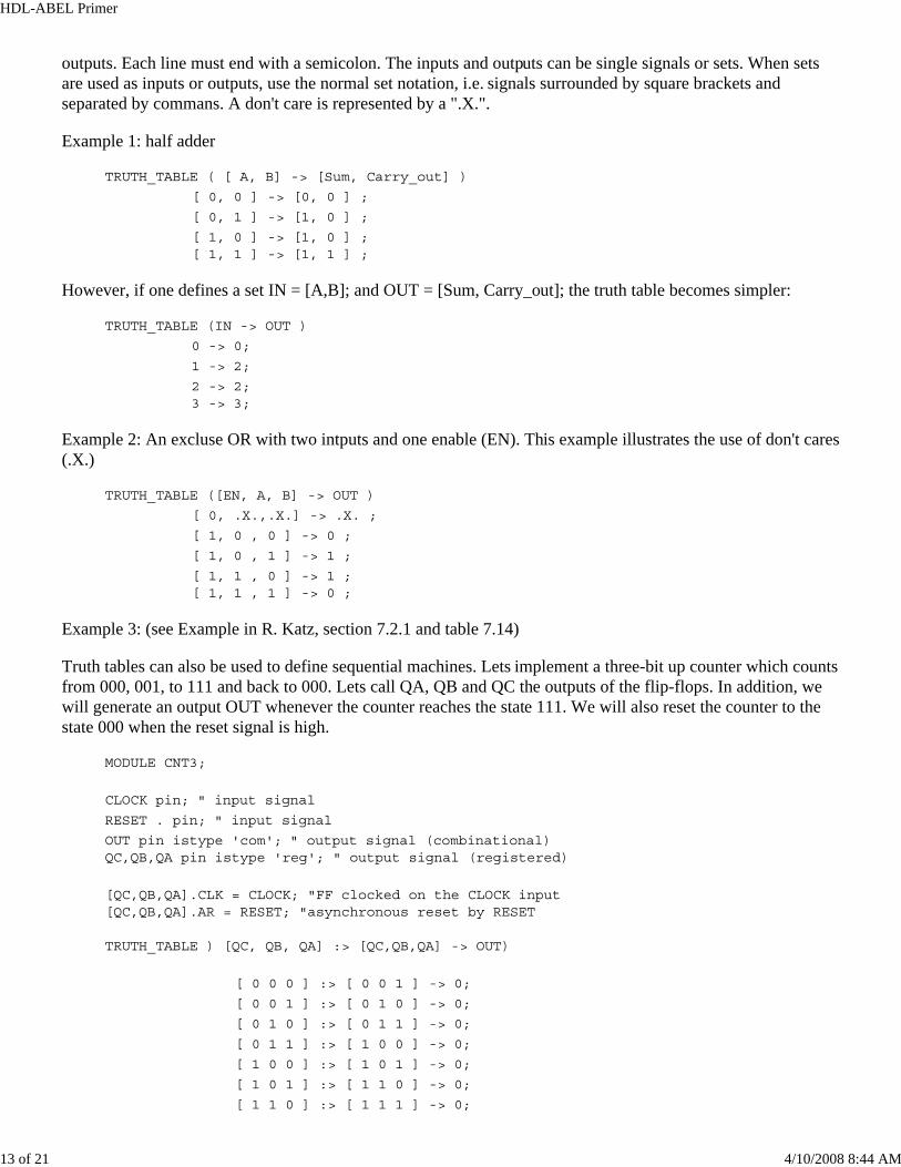
outputs. Each line must end with a semicolon. The inputs and outputs can be single signals or sets. When setsare used as inputs or outputs, use the normal set notation, i.e. signals surrounded by square brackets andseparated by commans. A don't care is represented by a ".X.".
Example 1: half adder
TRUTH_TABLE ( [ A, B] -> [Sum, Carry_out] )
[ 0, 0 ] -> [0, 0 ] ; [ 0, 1 ] -> [1, 0 ] ; [ 1, 0 ] -> [1, 0 ] ; [ 1, 1 ] -> [1, 1 ] ;
However, if one defines a set IN = [A,B]; and OUT = [Sum, Carry_out]; the truth table becomes simpler:
TRUTH_TABLE (IN -> OUT )
0 -> 0; 1 -> 2; 2 -> 2; 3 -> 3;
Example 2: An excluse OR with two intputs and one enable (EN). This example illustrates the use of don't cares(.X.)
TRUTH_TABLE ([EN, A, B] -> OUT )
[ 0, .X.,.X.] -> .X. ; [ 1, 0 , 0 ] -> 0 ; [ 1, 0 , 1 ] -> 1 ; [ 1, 1 , 0 ] -> 1 ; [ 1, 1 , 1 ] -> 0 ;
Example 3: (see Example in R. Katz, section 7.2.1 and table 7.14)
Truth tables can also be used to define sequential machines. Lets implement a three-bit up counter which countsfrom 000, 001, to 111 and back to 000. Lets call QA, QB and QC the outputs of the flip-flops. In addition, wewill generate an output OUT whenever the counter reaches the state 111. We will also reset the counter to thestate 000 when the reset signal is high.
MODULE CNT3;
CLOCK pin; " input signal RESET . pin; " input signal OUT pin istype 'com'; " output signal (combinational) QC,QB,QA pin istype 'reg'; " output signal (registered)
[QC,QB,QA].CLK = CLOCK; "FF clocked on the CLOCK input [QC,QB,QA].AR = RESET; "asynchronous reset by RESET
TRUTH_TABLE ) [QC, QB, QA] :> [QC,QB,QA] -> OUT)
[ 0 0 0 ] :> [ 0 0 1 ] -> 0; [ 0 0 1 ] :> [ 0 1 0 ] -> 0; [ 0 1 0 ] :> [ 0 1 1 ] -> 0; [ 0 1 1 ] :> [ 1 0 0 ] -> 0; [ 1 0 0 ] :> [ 1 0 1 ] -> 0; [ 1 0 1 ] :> [ 1 1 0 ] -> 0; [ 1 1 0 ] :> [ 1 1 1 ] -> 0;
HDL-ABEL Primer
14 of 21 4/10/2008 8:44 AM
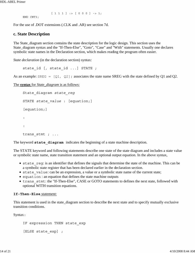
[ 1 1 1 ] :> [ 0 0 0 ] -> 1;END CNT3;
For the use of .DOT extensions (.CLK and .AR) see section 7d.
c. State Description
The State_diagram section contains the state description for the logic design. This section uses theState_diagram syntax and the "If-Then-Else", "Goto", "Case" and "With" statements. Usually one declaressymbolic state names in the Declaration section, which makes reading the program often easier.
State declaration (in the declaration section) syntax:
state_id [, state_id ...] STATE ;
As an example: SREG = [Q1, Q2]; associates the state name SREG with the state defined by Q1 and Q2.
The syntax for State_diagram is as follows:
State_diagram state_reg
STATE state_value : [equation;]
[equation;]
:
:
trans_stmt ; ...
The keyword state_diagram indicates the beginning of a state machine description.
The STATE keyword and following statements describe one state of the state diagram and includes a state valueor symbolic state name, state transition statement and an optional output equation. In the above syntax,
state_reg: is an identifier that defines the signals that determine the state of the machine. This can bea symbolic state register that has been declared earlier in the declaration section.state_value: can be an expression, a value or a symbolic state name of the current state;equation : an equation that defines the state machine outputstrans_stmt: the "If-Then-Else", CASE or GOTO statements to defines the next state, followed withoptional WITH transition equations.
If-Then-Else statement:
This statement is used in the state_diagram section to describe the next state and to specify mutually exclusivetransition conditions.
Syntax:
IF expression THEN state_exp
[ELSE state_exp] ;
HDL-ABEL Primer
15 of 21 4/10/2008 8:44 AM
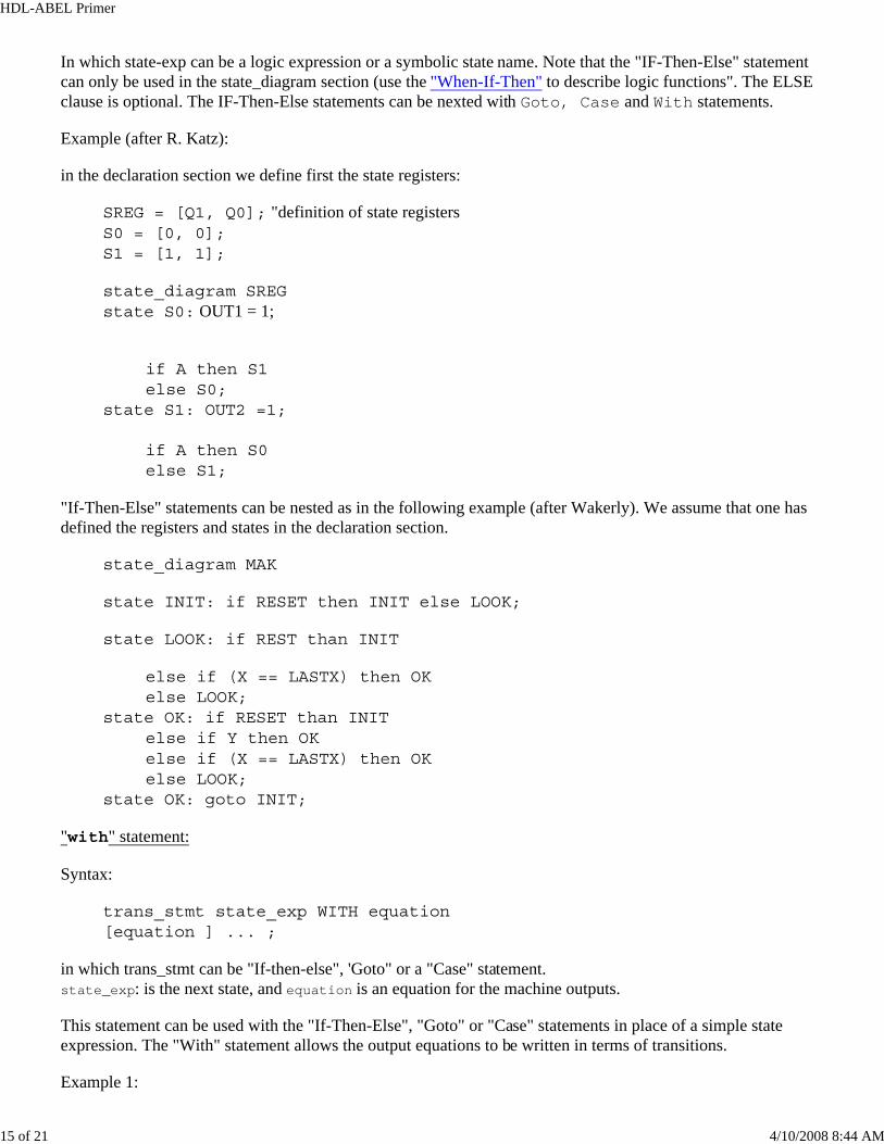
In which state-exp can be a logic expression or a symbolic state name. Note that the "IF-Then-Else" statementcan only be used in the state_diagram section (use the "When-If-Then" to describe logic functions". The ELSEclause is optional. The IF-Then-Else statements can be nexted with Goto, Case and With statements.
Example (after R. Katz):
in the declaration section we define first the state registers:
SREG = [Q1, Q0]; "definition of state registers S0 = [0, 0]; S1 = [1, 1];
state_diagram SREG state S0: OUT1 = 1;
if A then S1 else S0;
state S1: OUT2 =1; if A then S0 else S1;
"If-Then-Else" statements can be nested as in the following example (after Wakerly). We assume that one hasdefined the registers and states in the declaration section.
state_diagram MAK
state INIT: if RESET then INIT else LOOK;
state LOOK: if REST than INIT
else if (X == LASTX) then OK else LOOK;
state OK: if RESET than INITelse if Y then OK else if (X == LASTX) then OK else LOOK;
state OK: goto INIT;
"with" statement:
Syntax:
trans_stmt state_exp WITH equation [equation ] ... ;
in which trans_stmt can be "If-then-else", 'Goto" or a "Case" statement. state_exp: is the next state, and equation is an equation for the machine outputs.
This statement can be used with the "If-Then-Else", "Goto" or "Case" statements in place of a simple stateexpression. The "With" statement allows the output equations to be written in terms of transitions.
Example 1:
HDL-ABEL Primer
16 of 21 4/10/2008 8:44 AM
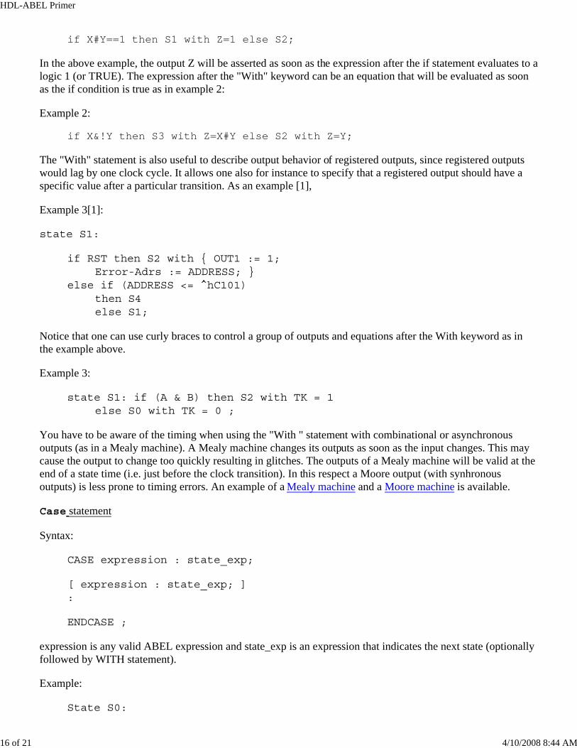
if X#Y==1 then S1 with Z=1 else S2;
In the above example, the output Z will be asserted as soon as the expression after the if statement evaluates to alogic 1 (or TRUE). The expression after the "With" keyword can be an equation that will be evaluated as soonas the if condition is true as in example 2:
Example 2:
if X&!Y then S3 with Z=X#Y else S2 with Z=Y;
The "With" statement is also useful to describe output behavior of registered outputs, since registered outputswould lag by one clock cycle. It allows one also for instance to specify that a registered output should have aspecific value after a particular transition. As an example [1],
Example 3[1]:
state S1:
if RST then S2 with { OUT1 := 1;Error-Adrs := ADDRESS; }
else if (ADDRESS <= ^hC101)then S4 else S1;
Notice that one can use curly braces to control a group of outputs and equations after the With keyword as inthe example above.
Example 3:
state S1: if (A & B) then S2 with TK = 1else S0 with TK = 0 ;
You have to be aware of the timing when using the "With " statement with combinational or asynchronousoutputs (as in a Mealy machine). A Mealy machine changes its outputs as soon as the input changes. This maycause the output to change too quickly resulting in glitches. The outputs of a Mealy machine will be valid at theend of a state time (i.e. just before the clock transition). In this respect a Moore output (with synhronousoutputs) is less prone to timing errors. An example of a Mealy machine and a Moore machine is available.
Case statement
Syntax:
CASE expression : state_exp;
[ expression : state_exp; ] :
ENDCASE ;
expression is any valid ABEL expression and state_exp is an expression that indicates the next state (optionallyfollowed by WITH statement).
Example:
State S0:

HDL-ABEL Primer
17 of 21 4/10/2008 8:44 AM
case ( A == 0) : S1;( A == 1) : S0;
endcase;
The case statement is used to list a sequence of mutually-exclusive transition conditions and corresponding nextstates. The CASE statement conditions must be mutually exclusive (no two transition conditions can be true atthe same time) or the resulting next state is unpredictable.
d. Dot extensions
One can use dot extensions to more precisely describe the behavior of the circuit. The signal extensions are veryhandy and provide a means to refer specifically to internal signals and nodes associated with a primary signal.
The syntax is
signal_name.ext
Some of the dot extensions are given in the following table. Extensions are not case sensitive. Some dotextensions are general purpose (also called architecture independent or pin-to-pin) and can used with a varietyof device architectures. Other dot extensions are used for specific classes of device architectures and are calledarchitecture-dependent or detailed dot extensions. In general, you can use either dot extensions.
Dot extension DescriptionArchitecture independent or pin-to-pin extensions.ACLR Asynchronous register reset .ASET Asynchronous register preset .CLK Clock input to an edge-triggered flip-flop .CLR Synchronous register reset
.COM Cominbational feedback from flip-flop data input
.FG Register feedback
.OE Output enable
.PIN Pin feedback
.SET Synchronous register preset Device Specific extensions (architecture dependent).D Data input to a D Flip flop .J J input to a JK flip-flop .K K input to a JK flip-flop .S S input to a SR flip-flop .R R input to a SR flip-flop .T T input to a T flip-flop .Q Register feedback.PR Register preset.RE Register reset
HDL-ABEL Primer
18 of 21 4/10/2008 8:44 AM
.AP Asynchronous register preset
.AR Asynchronous register reset
.SP Synchronous register preset
.SR Synchronous register reset
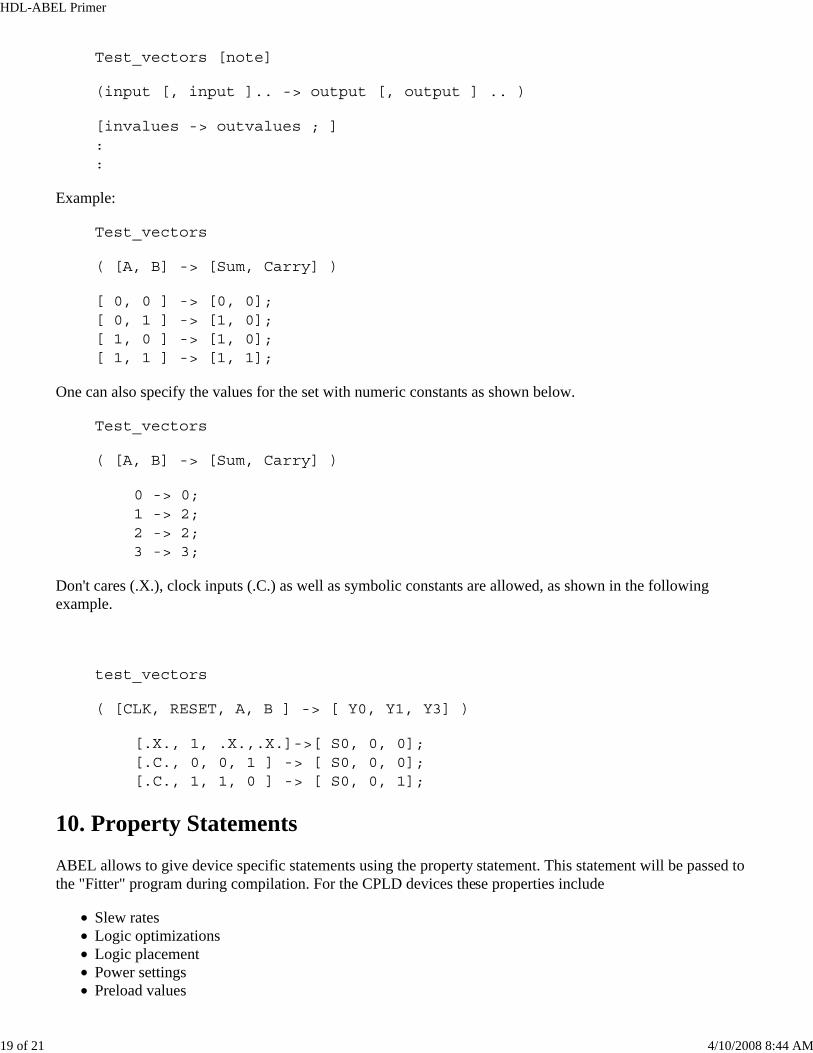
The figure below illustrates some of the extensions.
Figure 1: Illustration of DOT extensions for: (a) an architecture independent (pin-to-pin) and (b) arhitecturedependent D-type (or T-type) Flip Flop Architecture
Example 1:
[S6..S0].OE = ACTIVE;
which accesses the tri state control signal of the output buffers of the signals S6..S0. When ACTIVE is high, thesignals will be enabled, otherwise a high Z output is generated.
Example 2:
Q.AR = reset;
[Z.ar, Q.ar] = reset;
which resets to output of the registers (flip flops) to zero when reset is high.
9. Test vectors
Test vectors are optional and provide a means to verify the correct operation of a state machine. The vectorsspecify the expected logical operation of a logic device by explicitly giving the outputs as a function of theinputs.
Syntax:
HDL-ABEL Primer
19 of 21 4/10/2008 8:44 AM
Test_vectors [note]
(input [, input ].. -> output [, output ] .. )
[invalues -> outvalues ; ] : :
Example:
Test_vectors
( [A, B] -> [Sum, Carry] )
[ 0, 0 ] -> [0, 0]; [ 0, 1 ] -> [1, 0]; [ 1, 0 ] -> [1, 0]; [ 1, 1 ] -> [1, 1];
One can also specify the values for the set with numeric constants as shown below.
Test_vectors
( [A, B] -> [Sum, Carry] )
0 -> 0; 1 -> 2; 2 -> 2; 3 -> 3;
Don't cares (.X.), clock inputs (.C.) as well as symbolic constants are allowed, as shown in the followingexample.
test_vectors
( [CLK, RESET, A, B ] -> [ Y0, Y1, Y3] )
[.X., 1, .X.,.X.]->[ S0, 0, 0]; [.C., 0, 0, 1 ] -> [ S0, 0, 0]; [.C., 1, 1, 0 ] -> [ S0, 0, 1];
10. Property Statements
ABEL allows to give device specific statements using the property statement. This statement will be passed tothe "Fitter" program during compilation. For the CPLD devices these properties include
Slew ratesLogic optimizationsLogic placementPower settingsPreload values
HDL-ABEL Primer
20 of 21 4/10/2008 8:44 AM
11. Miscellaneous
a. Active-low declarations
Active low signals are defined with a "!" operator, as shown below,
!OUT pin istype 'com' ;
When this signal is used in a subsequent design description, it will be automatically complemented. As anexample consider the following description,
module EXAMPLE
A, B pin ;
!OUT pin istype 'com';
equations
OUT = A & !B # !A & B ;
end
In this example, the signal OUT is an XOR of A and B, i.e. OUT will be "1" (High, or ON) when only one ofthe inputs is "1", otherwise OUT is "0". However, the output pin is defined as !OUT , i.e. as an active-lowsignal, which means that the pin will go low "0" (Active-low or ON) when only one of the two inputs are "1".One could have obtained the same result by inverting the signal in the equations and declaring the pin to beOUT, as is shown in the following example. This is called explicit pin-to-pin active-low (because one uses active-low signals in the equations).
module EXAMPLE
A, B pin ;
OUT pin istype 'com';
equations
!OUT = A & !B # !A & B ;
end
Active low can be specified for a set as well. As an example lets define the sets A,B and C.
A = [A2,A1,A0]; "set declaration B = [B2,B1.B0]; "set declaration X = [X2,X1.X0]; "set declaration
!X = A & !B # !A & B;
The last equation is equivalent to writing
!X0 = A0 & !B0 # !A0 & B0; !X1 = A1 & !B1 # !A1 & B1;
HDL-ABEL Primer
21 of 21 4/10/2008 8:44 AM
!X2 = A2 & !B2 # !A2 & B2;
References
1. Xilinx-ABEL Design Software Reference Manual, Data I/O Corp., 1993.2. The ISP Application Guide and CPLD Data Book, Application Note XAPP075, 1997, Xilinx, SanJose, CA, 1997.3. D. Van den Bout, "Xilinx FPGA Student Manual", Prentice Hall, Englewoods Cliff, NJ, 1997.4. R. Katz, "Contemporary Logic Design," Benjamin/Cummings Publ. Comp., Redwood City, CA, 1995.5. J. Wakerly, "Digital Design," 3rd Edition, Prentice Hall, Englewoods Cliff, NJ, 2000.6. Xilinx Foundation Series, On-line documentation, Xilinx, San Jose, CA.
Acknowledgement
The support of Mr. Jason Feinsmith and the XilinxCorporation is acknowledged for providing the XILINXFoundation M1(TM) Software and FPGA Demoboards for educational purposes.
Back to ABEL Primer Contents Back to the Foundation Tutorial table of Contents Go to tutorial: Entering a Schematic | Entering a design with ABEL | Entering a design with VHDL| Simulation | Macrosand Hierarchical design | State Editor | Design Implementation | Configuring a device | Common Mistakes | Board description: FPGA Demoboard | XS40 | XS95 | Pinouts: XC4000 | XC9500.
Copyright, 2000, J. Van der Spiegel, <[email protected]> Sept. 26, 1997; Updated May 14, 2000