abc of drives - siemensw3.usa.siemens.com/drives/us/en/electric-drives/documents/drives...abc of...
TRANSCRIPT
ABC of DrivesConverters for Three-Phase AC and DC Drives
Manual · October 2009
Drives
Answers for industry.
© Siemens AG 2010
Related catalogs SINAMICS G130 D 11 Drive Converter Chassis Units SINAMICS G150 Drive Converter Cabinet Units E86060-K5511-A101-A4-7600
SINAMICS G110, SINAMICS G120 D 11.1 Standard Inverters SINAMICS G110D, SINAMICS G120D Distributed Inverters E86060-K5511-A111-A6-7600
SINAMICS GM150, SINAMICS SM150 D 12 Medium-Voltage Converters 0.8 MVA to 28 MVA E86060-K5512-A101-A2-7600
SINAMICS S120 D 21.3 Chassis Format Units and Cabinet Modules SINAMICS S150 Converter Cabinet Units E86060-K5521-A131-A2-7600
SINAMICS DCM D 23.1 Converter Units E86060-K5523-A111-A1-7600
Motion Control PM 21 SIMOTION, SINAMICS S120 and Motors for Production Machines E86060-K4921-A101-A1-7600
SINAMICS S110 PM 22 The Basic Positioning Drive E86060-K4922-A101-A1-7600
Industry Automation CA 01 and Motion Control Interactive Catalog (DVD) E86060-D4001-A510-C8-7600
SINAMICS – Low Voltage Engineering Manual SINAMICS G130, G150, S120 Chassis, S120 Cabinet Modules, S150
The SINAMICS – Low Voltage Engineering Manual offers users comprehensive support when configuring drives and associated system components. It includes subjects such as basic information on SINAMICS, a system description, EMC installation guidelines, configuring and engineering across all SINAMICS devices as well as dimensioning drives and motors. The Manual is not available in a printed form, but only as PDF. Siemens Intranet: http://www.siemens.com/sinamics
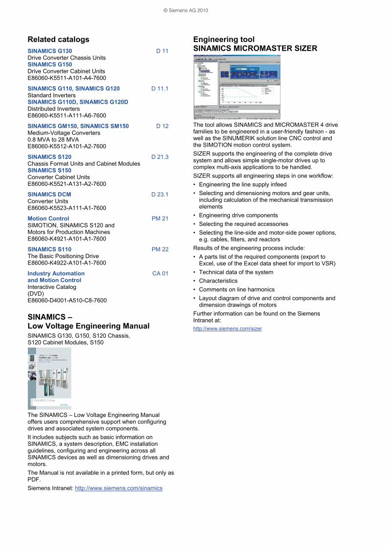
Engineering tool SINAMICS MICROMASTER SIZER
The tool allows SINAMICS and MICROMASTER 4 drive families to be engineered in a user-friendly fashion - as well as the SINUMERIK solution line CNC control and the SIMOTION motion control system. SIZER supports the engineering of the complete drive system and allows simple single-motor drives up to complex multi-axis applications to be handled. SIZER supports all engineering steps in one workflow: • Engineering the line supply infeed • Selecting and dimensioning motors and gear units,
including calculation of the mechanical transmission elements
• Engineering drive components • Selecting the required accessories • Selecting the line-side and motor-side power options,
e.g. cables, filters, and reactors Results of the engineering process include: • A parts list of the required components (export to
Excel, use of the Excel data sheet for import to VSR) • Technical data of the system • Characteristics • Comments on line harmonics • Layout diagram of drive and control components and
dimension drawings of motors Further information can be found on the Siemens Intranet at: http://www.siemens.com/sizer
© Siemens AG 2010
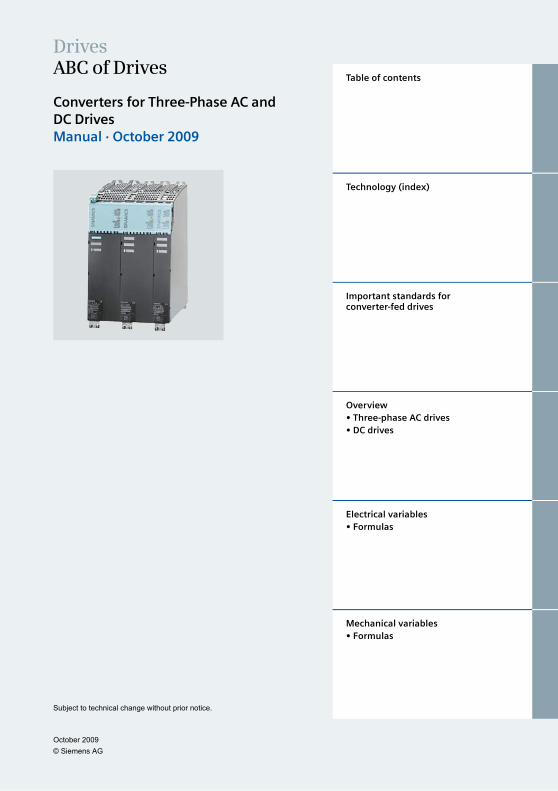
DrivesABC of Drives
Converters for Three-Phase AC andDC DrivesManual · October 2009
Subject to technical change without prior notice.
Table of contents
Technology (index)
Important standards forconverter-fed drives
Overview• Three-phase AC drives• DC drives
Electrical variables• Formulas
Mechanical variables• Formulas
October 2009© Siemens AG
October 2009© Siemens AG
Answers for industry.
Siemens Industry answers the challenges in the manufacturing
and the process industry as well as in the building automation
business. Our drive and automation solutions based on Totally
Integrated Automation (TIA) and Totally Integrated Power (TIP)
are employed in all kinds of industry. In the manufacturing
and the process industry. In industrial as well as in functional
buildings.
Siemens offers automation, drive, andlow-voltage switching technology aswell as industrial software from stan-dard products up to entire industry solu-tions. The industry software enables ourindustry customers to optimize the en-tire value chain – from product designand development throughmanufactureand sales up to after-sales service. Ourelectrical and mechanical componentsoffer integrated technologies for the en-tire drive train – from couplings to gearunits, from motors to control and drivesolutions for all engineering industries.Our technology platform TIP offers ro-bust solutions for power distribution.
Check out the opportunities ourautomation and drive solutions provide.And discover how you can sustainablyenhance your competitive edge with us.
ABC of Drives
October 2009 - I - © Siemens AG
Content
Technology (index)...........................................................................................................................................1 A ....................................................................................................................................................................1
Absolute encoder .....................................................................................................................................1 AC power controller..................................................................................................................................1 Acceleration time......................................................................................................................................3 Acceleration torque ..................................................................................................................................3 Accuracy...................................................................................................................................................3 Active Front End (AFE) ............................................................................................................................3 Active Infeed.............................................................................................................................................3 Active Interface Module............................................................................................................................4 Active Line Module...................................................................................................................................4 Actual value..............................................................................................................................................4 Adaptive control........................................................................................................................................5 Asynchronous motor ................................................................................................................................5 Armature circuit time constant..................................................................................................................5 Automatic restart ......................................................................................................................................5 Axis...........................................................................................................................................................5
B ....................................................................................................................................................................6 B2 connection...........................................................................................................................................6 B6 connection...........................................................................................................................................7 Balancing control......................................................................................................................................7 Basic Line Module....................................................................................................................................8 Blocksize ..................................................................................................................................................8 Booksize...................................................................................................................................................8 Brake control ............................................................................................................................................8 Braking chopper .......................................................................................................................................8 Braking Module ........................................................................................................................................9 Braking power ..........................................................................................................................................9 Braking resistor ........................................................................................................................................9 Braking torque ..........................................................................................................................................9 Breakaway torque ....................................................................................................................................9 Bridge connection.....................................................................................................................................9 Brushless excitation .................................................................................................................................9
C ..................................................................................................................................................................10 Cable length ...........................................................................................................................................10 CAD CREATOR .....................................................................................................................................10 Capacitor Module ...................................................................................................................................10 Cascade control .....................................................................................................................................10 Central Braking Module (CBM) ..............................................................................................................11 Chassis...................................................................................................................................................11 Chopper..................................................................................................................................................11 Circulating current ..................................................................................................................................11 Circulating current carrying converter connection..................................................................................11 Circulating current reactor......................................................................................................................11 Circulating current-free converter connection ........................................................................................11 Clock frequency......................................................................................................................................11 Closed-loop control stability ...................................................................................................................11 Closed-loop position control...................................................................................................................12 Closed-loop speed control .....................................................................................................................12 Cold plate cooling...................................................................................................................................12 Commutating dip ....................................................................................................................................13
ABC of Drives
- II - October 2009 © Siemens AG
Commutating reactor ............................................................................................................................. 13 Commutation ......................................................................................................................................... 13 Commutation reactive power................................................................................................................. 14 Control characteristic............................................................................................................................. 14 Control deviation.................................................................................................................................... 14 Control loop ........................................................................................................................................... 14 Control loop, dynamic behavior............................................................................................................. 15 Control precision.................................................................................................................................... 15 Control pulse ......................................................................................................................................... 15 Control reactive power........................................................................................................................... 15 Control Unit............................................................................................................................................ 16 Controlled system.................................................................................................................................. 16 Controller ............................................................................................................................................... 16 Converter ............................................................................................................................................... 16 Converter-fed motor .............................................................................................................................. 17 Counter torque....................................................................................................................................... 17 Current limiting ...................................................................................................................................... 17 Cycloconverter....................................................................................................................................... 18
D ................................................................................................................................................................. 19 DC chopper controller............................................................................................................................ 19 DC drives............................................................................................................................................... 20 DC link ................................................................................................................................................... 20 DC link converters ................................................................................................................................. 20 Dead time .............................................................................................................................................. 22 Demand factor ....................................................................................................................................... 22 Derating ................................................................................................................................................. 22 Diode ..................................................................................................................................................... 23 Direct measuring system....................................................................................................................... 23 Displacement factor............................................................................................................................... 23 Double pulse.......................................................................................................................................... 23 Double-way converter............................................................................................................................ 23 Drive Control Chart (DCC)..................................................................................................................... 24 Drive efficiency ...................................................................................................................................... 24 Drive line-up .......................................................................................................................................... 24 Drive/drive system................................................................................................................................. 24 Drive-CLiQ............................................................................................................................................. 24 Driver stage ........................................................................................................................................... 24 Droop..................................................................................................................................................... 25 Duty types.............................................................................................................................................. 25 Dynamic braking.................................................................................................................................... 25 Dynamic response................................................................................................................................. 25
E.................................................................................................................................................................. 26 Edge modulation.................................................................................................................................... 26 Electromagnetic compatibility (EMC) .................................................................................................... 26 Electronic rating plate ............................................................................................................................ 26 Encoder ................................................................................................................................................. 27 Energy recovery .................................................................................................................................... 27 External encoder ................................................................................................................................... 27 Externally-commutated converter.......................................................................................................... 27
F.................................................................................................................................................................. 28 Field circuit time constant ...................................................................................................................... 28 Field-oriented control............................................................................................................................. 28 Field power supply................................................................................................................................. 29 Field weakening..................................................................................................................................... 29
ABC of Drives
October 2009 - III - © Siemens AG
Field-weakening control .........................................................................................................................29 Field-weakening range...........................................................................................................................30 Final controlling element ........................................................................................................................30 Firing pulse.............................................................................................................................................30 Flying restart...........................................................................................................................................30 Four-quadrant operation ........................................................................................................................31 Free function blocks ...............................................................................................................................31 Free-wheeling arm .................................................................................................................................31 Free-wheeling current ............................................................................................................................31 Free-wheeling rectifier............................................................................................................................31 Frequency converter ..............................................................................................................................31 Fundamental content, harmonic content (distortion factor) ...................................................................32
G..................................................................................................................................................................33 Gating unit ..............................................................................................................................................33 Group drive.............................................................................................................................................33
H ..................................................................................................................................................................34 Half-controlled circuits............................................................................................................................34 Harmonic suppression ...........................................................................................................................34 Harmonics ..............................................................................................................................................35 Hold-off angle .........................................................................................................................................35 Hold-off time ...........................................................................................................................................35
I....................................................................................................................................................................36 I2t value...................................................................................................................................................36 IGBT .......................................................................................................................................................36 IGCT.......................................................................................................................................................37 Incremental encoder ..............................................................................................................................37 Induction motor.......................................................................................................................................37 Inverse parallel connection ....................................................................................................................38 Inverter commutation fault......................................................................................................................39 Inverter operation ...................................................................................................................................39 Inverter stability limit...............................................................................................................................40 IT line supply ..........................................................................................................................................40
K ..................................................................................................................................................................41 Kinetic buffering......................................................................................................................................41
L ..................................................................................................................................................................42 Line filters ...............................................................................................................................................42 Line harmonics .......................................................................................................................................42 Line Module............................................................................................................................................42 Line reactor ............................................................................................................................................42 Line supply configuration .......................................................................................................................42 Line-commutated converters..................................................................................................................42 Load characteristic .................................................................................................................................43 Load cycle ..............................................................................................................................................43 Load torque ............................................................................................................................................43 Load-commutated converters ................................................................................................................43
M..................................................................................................................................................................44 Manipulated variable ..............................................................................................................................44 Model......................................................................................................................................................44 Modular Multilevel Converter (M²LC) .....................................................................................................44 Modulation..............................................................................................................................................45 Moment of inertia....................................................................................................................................45 MOSFET ................................................................................................................................................45 MOTION-CONNECT..............................................................................................................................45
ABC of Drives
- IV - October 2009 © Siemens AG
Motor encoder ....................................................................................................................................... 45 Motor identification ................................................................................................................................ 45 Motor Module......................................................................................................................................... 46 Motor reactor ......................................................................................................................................... 46 Multi-level inverter (Perfect Harmony)................................................................................................... 46 Multi-quadrant drive............................................................................................................................... 47
N ................................................................................................................................................................. 48 Nominal value........................................................................................................................................ 48
O ................................................................................................................................................................. 49 On period............................................................................................................................................... 49 Optimization........................................................................................................................................... 49 Output frequency ................................................................................................................................... 49 Output reactor........................................................................................................................................ 49 Output voltage ....................................................................................................................................... 49 Overload capability ................................................................................................................................ 50 Overshoot .............................................................................................................................................. 50
P.................................................................................................................................................................. 51 Phase angle control............................................................................................................................... 51 Phase reactors ...................................................................................................................................... 51 Polyphase machines ............................................................................................................................. 51 Position controller .................................................................................................................................. 52 Power factor .......................................................................................................................................... 52 Power Module........................................................................................................................................ 52 Pre-charging .......................................................................................................................................... 52 Pre-charging circuit................................................................................................................................ 52 PROFIBUS ............................................................................................................................................ 53 PROFIdrive............................................................................................................................................ 53 PROFINET ............................................................................................................................................ 53 Pulsating DC operation.......................................................................................................................... 53 Pulse amplifiers ..................................................................................................................................... 53 Pulse frequency..................................................................................................................................... 54 Pulse number ........................................................................................................................................ 54 Pulse pattern, optimized........................................................................................................................ 54 Pulse trains............................................................................................................................................ 54 PWM inverter......................................................................................................................................... 54
R ................................................................................................................................................................. 55 Ramp-function generator....................................................................................................................... 55 Rated value ........................................................................................................................................... 55 Reactive power (Fundamental-frequency reactive power).................................................................... 55 Reactive power compensation .............................................................................................................. 57 Recovery time........................................................................................................................................ 57 Rectifier.................................................................................................................................................. 57 Rectifier operation ................................................................................................................................. 58 Redundant operation, operating mode (n+m) ....................................................................................... 58 Regenerative braking ............................................................................................................................ 58 Regenerative feedback.......................................................................................................................... 58 Resolver................................................................................................................................................. 59 Restart ................................................................................................................................................... 59 Ripple..................................................................................................................................................... 60 Rise time................................................................................................................................................ 60 Rotor time constant ............................................................................................................................... 60
ABC of Drives
October 2009 - V - © Siemens AG
S ..................................................................................................................................................................61 Safety Integrated....................................................................................................................................61 Sampling time.........................................................................................................................................61 Self-commutated converter ....................................................................................................................61 Sensorless operation..............................................................................................................................61 Series resonant circuit............................................................................................................................62 Servo control ..........................................................................................................................................62 Servo drive .............................................................................................................................................62 Setpoint ..................................................................................................................................................62 Setpoint generator..................................................................................................................................62 Settling time............................................................................................................................................62 Silicon carbide, SiC ................................................................................................................................62 Sine-wave filter.......................................................................................................................................62 Single-quadrant drive .............................................................................................................................63 SIZER.....................................................................................................................................................63 Skip frequency band...............................................................................................................................63 Slip frequency.........................................................................................................................................63 Smart Line Module .................................................................................................................................63 Smoothing capacitor...............................................................................................................................64 Smoothing reactor ..................................................................................................................................64 Snubber circuit .......................................................................................................................................64 Space-vector modulation .......................................................................................................................65 Speed control range...............................................................................................................................65 Speed operating range...........................................................................................................................65 Speed-torque characteristic ...................................................................................................................65 Stacked cell inverter ...............................................................................................................................66 Stalling....................................................................................................................................................66 STARTER...............................................................................................................................................66 Starting time ...........................................................................................................................................66 Step-down controller ..............................................................................................................................66 Step-up controller ...................................................................................................................................66 Synchronous motor ................................................................................................................................67 Synchronous servomotor .......................................................................................................................67 System deviation ....................................................................................................................................67
T ..................................................................................................................................................................68 Tachogenerator ......................................................................................................................................68 THD ........................................................................................................................................................68 Three-level inverter ................................................................................................................................68 Three-phase AC drives ..........................................................................................................................69 Three-phase AC power controller ..........................................................................................................69 Three-phase motor.................................................................................................................................69 Thyristor .................................................................................................................................................70 TN line supply.........................................................................................................................................70 Torque control ........................................................................................................................................70 Torque motor..........................................................................................................................................71 Torque-free interval ................................................................................................................................71 Totally Integrated Automation (TIA) .......................................................................................................71 Transient response.................................................................................................................................71 TT line supply .........................................................................................................................................71
V ..................................................................................................................................................................72 Vector control .........................................................................................................................................72 V/f control ...............................................................................................................................................72
ABC of Drives
- VI - October 2009 © Siemens AG
Important standards for converter-fed drives ............................................................................................ 73
Three-phase AC drives.................................................................................................................................. 74
DC drives ........................................................................................................................................................ 75
Electrical variables ........................................................................................................................................ 76 Formulas.................................................................................................................................................... 76
Mechanical variables..................................................................................................................................... 80 Formulas.................................................................................................................................................... 80
ABC of Drives
October 2009 - 1 - © Siemens AG
Technology (index)
A
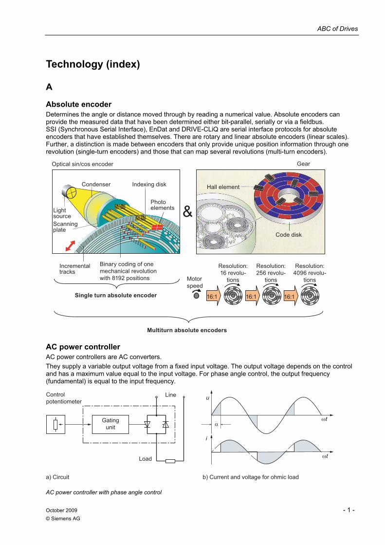
Absolute encoder Determines the angle or distance moved through by reading a numerical value. Absolute encoders can provide the measured data that have been determined either bit-parallel, serially or via a fieldbus. SSI (Synchronous Serial Interface), EnDat and DRIVE-CLiQ are serial interface protocols for absolute encoders that have established themselves. There are rotary and linear absolute encoders (linear scales). Further, a distinction is made between encoders that only provide unique position information through one revolution (single-turn encoders) and those that can map several revolutions (multi-turn encoders).
Gear
Code disk
Single turn absolute encoder
Multiturn absolute encoders
&
Hall element
Incremental tracks
16:1 16:1
Motor speed
Binary coding of one mechanical revolution with 8192 positions
Resolution: 16 revolu-
tions
Resolution: 256 revolu-
tions
Resolution: 4096 revolu-
tions
16:1
Optical sin/cos encoder
Light source
Photo elements
Indexing disk
Scanningplate
Condenser
AC power controller AC power controllers are AC converters. They supply a variable output voltage from a fixed input voltage. The output voltage depends on the control and has a maximum value equal to the input voltage. For phase angle control, the output frequency (fundamental) is equal to the input frequency.
Control potentiometer
b) Current and voltage for ohmic loada) Circuit
Load
Line
Gating unit
i
u
AC power controller with phase angle control
ABC of Drives
- 2 - October 2009 © Siemens AG
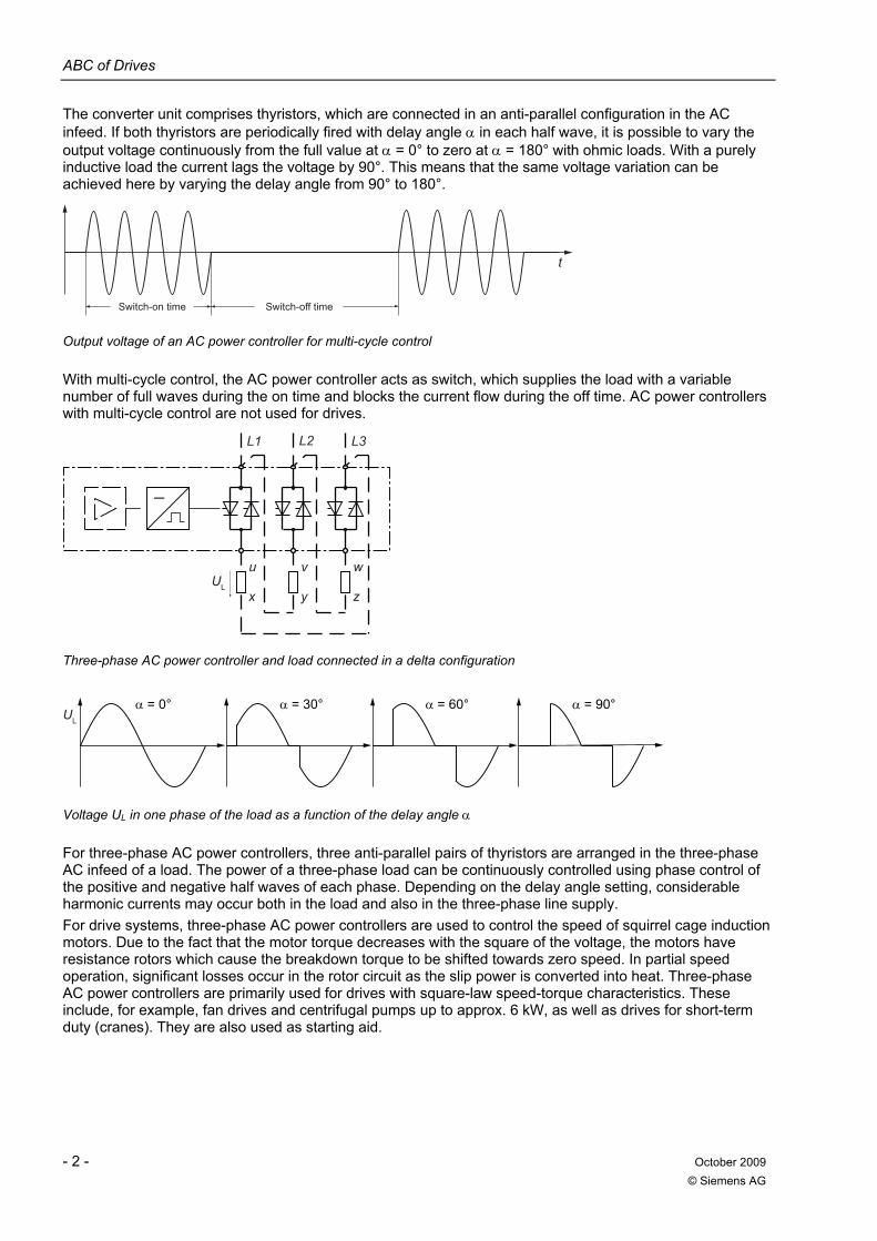
The converter unit comprises thyristors, which are connected in an anti-parallel configuration in the AC infeed. If both thyristors are periodically fired with delay angle α in each half wave, it is possible to vary the output voltage continuously from the full value at α = 0° to zero at α = 180° with ohmic loads. With a purely inductive load the current lags the voltage by 90°. This means that the same voltage variation can be achieved here by varying the delay angle from 90° to 180°.
Switch-off timeSwitch-on time
t
Output voltage of an AC power controller for multi-cycle control
With multi-cycle control, the AC power controller acts as switch, which supplies the load with a variable number of full waves during the on time and blocks the current flow during the off time. AC power controllers with multi-cycle control are not used for drives.
_
uUL
x
v
y
w
z
L1 L2 L3
Three-phase AC power controller and load connected in a delta configuration
UL
α = 0° α = 30° α = 60° α = 90°
Voltage UL in one phase of the load as a function of the delay angle α
For three-phase AC power controllers, three anti-parallel pairs of thyristors are arranged in the three-phase AC infeed of a load. The power of a three-phase load can be continuously controlled using phase control of the positive and negative half waves of each phase. Depending on the delay angle setting, considerable harmonic currents may occur both in the load and also in the three-phase line supply. For drive systems, three-phase AC power controllers are used to control the speed of squirrel cage induction motors. Due to the fact that the motor torque decreases with the square of the voltage, the motors have resistance rotors which cause the breakdown torque to be shifted towards zero speed. In partial speed operation, significant losses occur in the rotor circuit as the slip power is converted into heat. Three-phase AC power controllers are primarily used for drives with square-law speed-torque characteristics. These include, for example, fan drives and centrifugal pumps up to approx. 6 kW, as well as drives for short-term duty (cranes). They are also used as starting aid.
ABC of Drives
October 2009 - 3 - © Siemens AG
Acceleration time See Starting time.
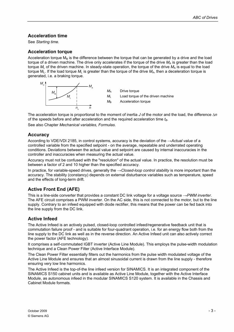
Acceleration torque Acceleration torque MB is the difference between the torque that can be generated by a drive and the load torque of a driven machine. The drive only accelerates if the torque of the drive MA is greater than the load torque ML of the driven machine. In steady-state operation, the torque of the drive MA is equal to the load torque ML. If the load torque ML is greater than the torque of the drive MA, then a deceleration torque is generated, i.e. a braking torque.
Md
MBML
MA
nn n
MA Drive torque ML Load torque of the driven machine MB Acceleration torque
The acceleration torque is proportional to the moment of inertia J of the motor and the load, the difference ∆n of the speeds before and after acceleration and the required acceleration time tB. See also Chapter Mechanical variables, Formulas.
Accuracy According to VDE/VDI 2185, in control systems, accuracy is the deviation of the →Actual value of a controlled variable from the specified setpoint - on the average, repeatable and underrated operating conditions. Deviations between the actual value and setpoint are caused by internal inaccuracies in the controller and inaccuracies when measuring the actual value. Accuracy must not be confused with the "resolution" of the actual value. In practice, the resolution must be between a factor of 2 and 10 higher than the specified accuracy. In practice, for variable-speed drives, generally the →Closed-loop control stability is more important than the accuracy. The stability (constancy) depends on external disturbance variables such as temperature, speed and the effects of long-term drift.
Active Front End (AFE) This is a line-side converter that provides a constant DC link voltage for a voltage source →PWM inverter. The AFE circuit comprises a PWM inverter. On the AC side, this is not connected to the motor, but to the line supply. Contrary to an infeed equipped with diode rectifier, this means that the power can be fed back into the line supply from the DC link.
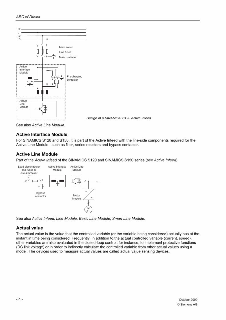
Active Infeed The Active Infeed is an actively pulsed, closed-loop controlled infeed/regenerative feedback unit that is commutation failure proof - and is suitable for four-quadrant operation, i.e. for an energy flow both from the line supply to the DC link as well as in the reverse direction. An Active Infeed unit can also actively correct the power factor (AFE technology). It comprises a self-commutated IGBT inverter (Active Line Module). This employs the pulse-width modulation technique and a Clean Power Filter (Active Interface Module). The Clean Power Filter essentially filters out the harmonics from the pulse width modulated voltage of the Active Line Module and ensures that an almost sinusoidal current is drawn from the line supply - therefore ensuring very low line harmonics. The Active Infeed is the top-of-the line infeed version for SINAMICS. It is an integrated component of the SINAMICS S150 cabinet units and is available as Active Line Module, together with the Active Interface Module, as autonomous infeed in the modular SINAMICS S120 system. It is available in the Chassis and Cabinet Module formats.
ABC of Drives
- 4 - October 2009 © Siemens AG
Line fuses
Pre-charging contactor
Main contactor
Main switch
PEL1L2L3
ActiveInterfaceModule
ActiveLineModule
Design of a SINAMICS S120 Active Infeed See also Active Line Module.
Active Interface Module For SINAMICS S120 and S150, it is part of the Active Infeed with the line-side components required for the Active Line Module - such as filter, series resistors and bypass contactor.
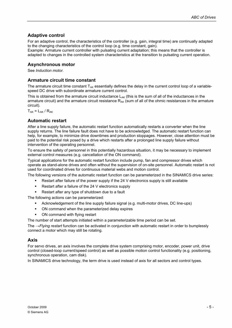
Active Line Module Part of the Active Infeed of the SINAMICS S120 and SINAMICS S150 series (see Active Infeed).
Bypass contactor
Load disconnector and fuses or
circuit-breaker
MotorModule
Active InterfaceModule
Active LineModule
M3
. . .
=
See also Active Infeed, Line Module, Basic Line Module, Smart Line Module.
Actual value The actual value is the value that the controlled variable (or the variable being considered) actually has at the instant in time being considered. Frequently, in addition to the actual controlled variable (current, speed), other variables are also evaluated in the closed-loop control; for instance, to implement protective functions (DC link voltage) or in order to indirectly calculate the controlled variable from other actual values using a model. The devices used to measure actual values are called actual value sensing devices.
ABC of Drives
October 2009 - 5 - © Siemens AG
Adaptive control For an adaptive control, the characteristics of the controller (e.g. gain, integral time) are continually adapted to the changing characteristics of the control loop (e.g. time constant, gain). Example: Armature current controller with pulsating current adaptation; this means that the controller is adapted to changes in the controlled system characteristics at the transition to pulsating current operation.
Asynchronous motor See Induction motor.
Armature circuit time constant The armature circuit time constant TAK essentially defines the delay in the current control loop of a variable-speed DC drive with subordinate armature current control. This is obtained from the armature circuit inductance LAK (this is the sum of all of the inductances in the armature circuit) and the armature circuit resistance RAK (sum of all of the ohmic resistances in the armature circuit). TAK = LAK / RAK
Automatic restart After a line supply failure, the automatic restart function automatically restarts a converter when the line supply returns. The line failure fault does not have to be acknowledged. The automatic restart function can help, for example, to minimize drive downtimes and production stoppages. However, close attention must be paid to the potential risk posed by a drive which restarts after a prolonged line supply failure without intervention of the operating personnel. To ensure the safety of personnel in this potentially hazardous situation, it may be necessary to implement external control measures (e.g. cancellation of the ON command). Typical applications for the automatic restart function include pump, fan and compressor drives which operate as stand-alone drives and often without the supervision of on-site personnel. Automatic restart is not used for coordinated drives for continuous material webs and motion control. The following versions of the automatic restart function can be parameterized in the SINAMICS drive series:
Restart after failure of the power supply if the 24 V electronics supply is still available Restart after a failure of the 24 V electronics supply Restart after any type of shutdown due to a fault
The following actions can be parameterized: Acknowledgement of the line supply failure signal (e.g. multi-motor drives, DC line-ups) ON command when the parameterized delay expires ON command with flying restart
The number of start attempts initiated within a parameterizable time period can be set. The →Flying restart function can be activated in conjunction with automatic restart in order to bumplessly connect a motor which may still be rotating.
Axis For servo drives, an axis involves the complete drive system comprising motor, encoder, power unit, drive control (closed-loop current/speed control) as well as possible motion control functionality (e.g. positioning, synchronous operation, cam disk). In SINAMICS drive technology, the term drive is used instead of axis for all sectors and control types.
ABC of Drives
- 6 - October 2009 © Siemens AG
B
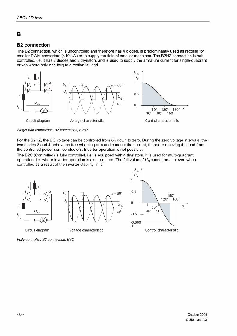
B2 connection The B2 connection, which is uncontrolled and therefore has 4 diodes, is predominantly used as rectifier for smaller PWM converters (<10 kW) or to supply the field of smaller machines. The B2HZ connection is half controlled, i.e. it has 2 diodes and 2 thyristors and is used to supply the armature current for single-quadrant drives where only one torque direction is used.
Voltage characteristicCircuit diagram Control characteristic
0.5
Udi
1
0
30° 90° 150°60° 120° 180°
UL
IL
Id
Ud
UL4
2
3
1
L
M
Single-pair controllable B2 connection, B2HZ
For the B2HZ, the DC voltage can be controlled from Udi down to zero. During the zero voltage intervals, the two diodes 3 and 4 behave as free-wheeling arm and conduct the current, therefore relieving the load from the controlled power semiconductors. Inverter operation is not possible. The B2C (Controlled) is fully controlled, i.e. is equipped with 4 thyristors. It is used for multi-quadrant operation, i.e. where inverter operation is also required. The full value of Udi cannot be achieved when controlled as a result of the inverter stability limit.
-0.866
-0.5
Control characteristicVoltage characteristicCircuit diagram
0.5
Udi
-1
1
0
30° 90°
150°
60°
120° 180°4
2
3
1
L
MId
UL
IL
Ud
UL
Fully-controlled B2 connection, B2C
ABC of Drives
October 2009 - 7 - © Siemens AG
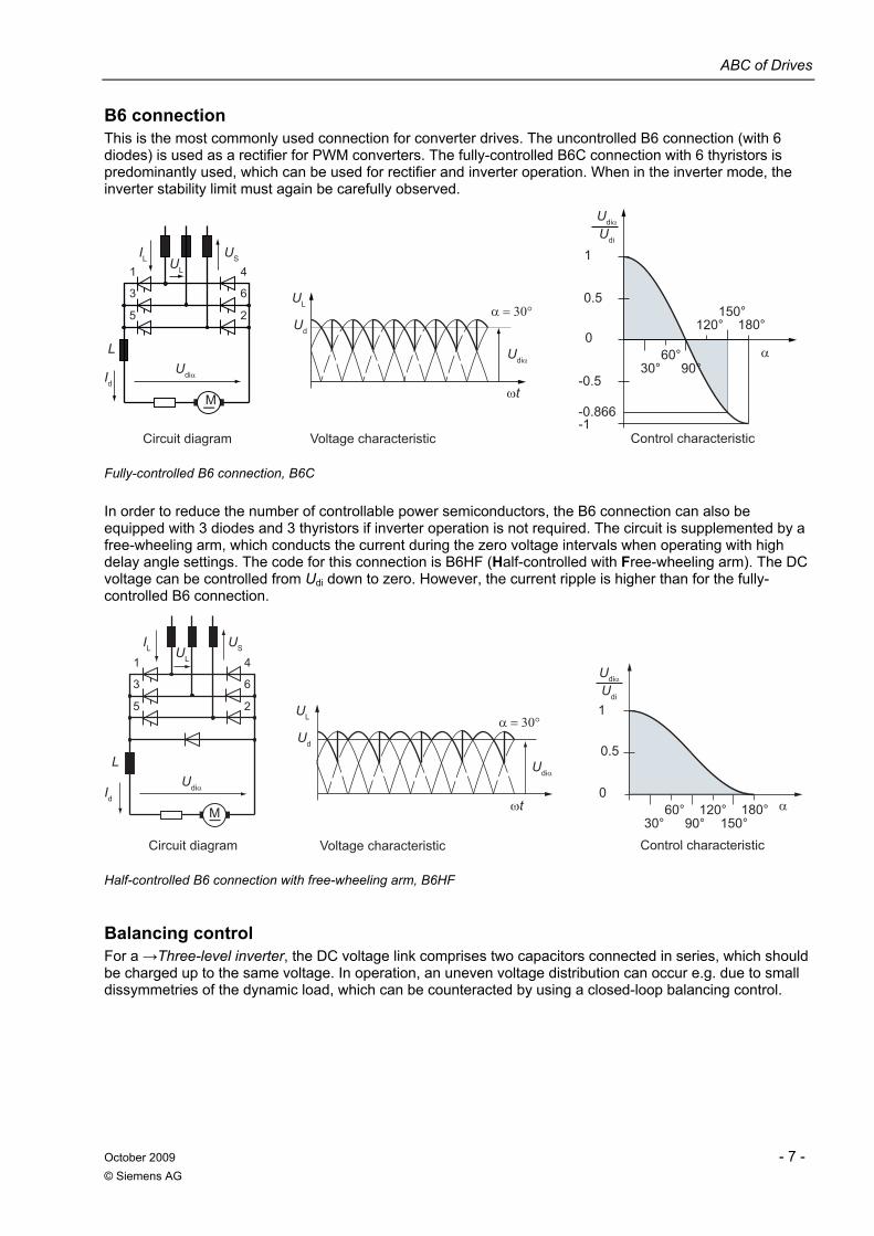
B6 connection This is the most commonly used connection for converter drives. The uncontrolled B6 connection (with 6 diodes) is used as a rectifier for PWM converters. The fully-controlled B6C connection with 6 thyristors is predominantly used, which can be used for rectifier and inverter operation. When in the inverter mode, the inverter stability limit must again be carefully observed.
-1-0.866
-0.5
Control characteristicVoltage characteristicCircuit diagram
0.5
Udi
Id
USUL
IL
Ud
UL2
6
4
5
1
0
30° 90°
150°
60°
120° 180°
3
1
L
M
Fully-controlled B6 connection, B6C
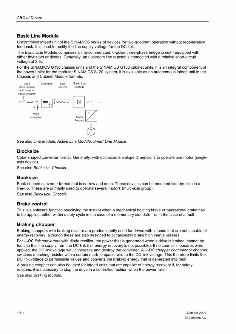
In order to reduce the number of controllable power semiconductors, the B6 connection can also be equipped with 3 diodes and 3 thyristors if inverter operation is not required. The circuit is supplemented by a free-wheeling arm, which conducts the current during the zero voltage intervals when operating with high delay angle settings. The code for this connection is B6HF (Half-controlled with Free-wheeling arm). The DC voltage can be controlled from Udi down to zero. However, the current ripple is higher than for the fully-controlled B6 connection.
Control characteristicVoltage characteristicCircuit diagram
0.5
Udi
Id
USUL
IL
Ud
UL2
6
4
5 1
0
30° 90° 150°60° 120° 180°
3
1
L
M
Half-controlled B6 connection with free-wheeling arm, B6HF
Balancing control For a →Three-level inverter, the DC voltage link comprises two capacitors connected in series, which should be charged up to the same voltage. In operation, an uneven voltage distribution can occur e.g. due to small dissymmetries of the dynamic load, which can be counteracted by using a closed-loop balancing control.
ABC of Drives
- 8 - October 2009 © Siemens AG
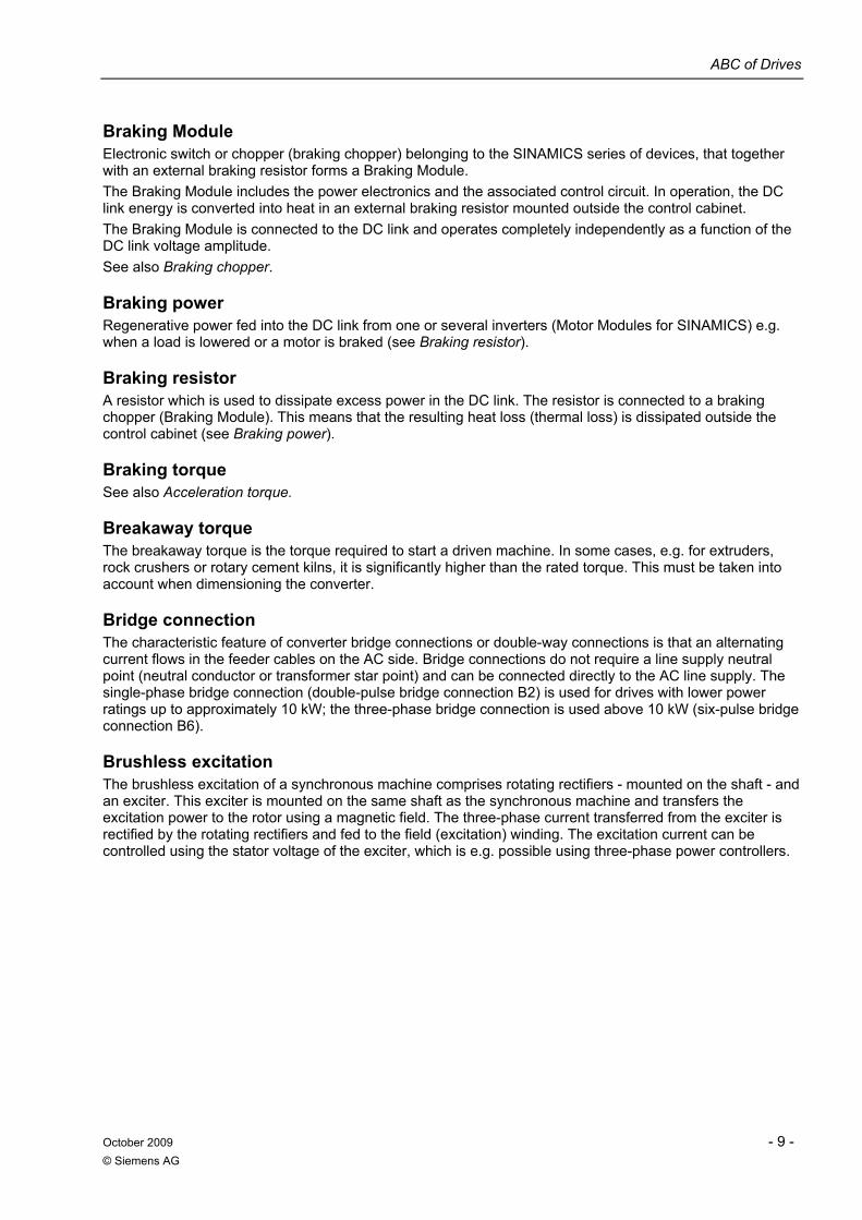
Basic Line Module Uncontrolled infeed unit of the SINAMICS series of devices for two-quadrant operation without regenerative feedback. It is used to rectify the line supply voltage for the DC link. The Basic Line Module comprises a line-commutated, 6-pulse three-phase bridge circuit - equipped with either thyristors or diodes. Generally, an upstream line reactor is connected with a relative short-circuit voltage of 2 %. For the SINAMICS G130 chassis units and the SINAMICS G150 cabinet units, it is an integral component of the power units; for the modular SINAMICS S120 system, it is available as an autonomous infeed unit in the Chassis and Cabinet Module formats.
Load disconnector and fuses or
circuit-breaker
Line reactor
Line filter
Main contactor
ModuleBasic Line
ModuleMotor
. . .
=
3M
See also Line Module, Active Line Module, Smart Line Module.
Blocksize Cube-shaped converter format. Generally, with optimized envelope dimensions to operate one motor (single-axis device). See also Booksize, Chassis.
Booksize Book-shaped converter format that is narrow and deep. These devices can be mounted side-by-side in a line-up. These are primarily used to operate several motors (multi-axis group). See also Blocksize, Chassis.
Brake control This is a software function specifying the instant when a mechanical holding brake or operational brake has to be applied; either within a duty cycle in the case of a momentary standstill - or in the case of a fault.
Braking chopper Braking choppers with braking resistor are predominantly used for drives with infeeds that are not capable of energy recovery, although these are also designed to occasionally brake high inertia masses. For →DC link converters with diode rectifier, the power that is generated when a drive is braked, cannot be fed into the line supply from the DC link (i.e. energy recovery is not possible). If no counter-measures were applied, the DC link voltage would increase and destroy the converter. A →DC chopper controller or chopper switches a braking resistor with a certain mark-to-space ratio to the DC link voltage. This therefore limits the DC link voltage to permissible values and converts the braking energy that is generated into heat. A braking chopper can also be used for infeed units that are capable of energy recovery if, for safety reasons, it is necessary to stop the drive in a controlled fashion when the power fails. See also Braking Module.
ABC of Drives
October 2009 - 9 - © Siemens AG
Braking Module Electronic switch or chopper (braking chopper) belonging to the SINAMICS series of devices, that together with an external braking resistor forms a Braking Module. The Braking Module includes the power electronics and the associated control circuit. In operation, the DC link energy is converted into heat in an external braking resistor mounted outside the control cabinet. The Braking Module is connected to the DC link and operates completely independently as a function of the DC link voltage amplitude. See also Braking chopper.
Braking power Regenerative power fed into the DC link from one or several inverters (Motor Modules for SINAMICS) e.g. when a load is lowered or a motor is braked (see Braking resistor).
Braking resistor A resistor which is used to dissipate excess power in the DC link. The resistor is connected to a braking chopper (Braking Module). This means that the resulting heat loss (thermal loss) is dissipated outside the control cabinet (see Braking power).
Braking torque See also Acceleration torque.
Breakaway torque The breakaway torque is the torque required to start a driven machine. In some cases, e.g. for extruders, rock crushers or rotary cement kilns, it is significantly higher than the rated torque. This must be taken into account when dimensioning the converter.
Bridge connection The characteristic feature of converter bridge connections or double-way connections is that an alternating current flows in the feeder cables on the AC side. Bridge connections do not require a line supply neutral point (neutral conductor or transformer star point) and can be connected directly to the AC line supply. The single-phase bridge connection (double-pulse bridge connection B2) is used for drives with lower power ratings up to approximately 10 kW; the three-phase bridge connection is used above 10 kW (six-pulse bridge connection B6).
Brushless excitation The brushless excitation of a synchronous machine comprises rotating rectifiers - mounted on the shaft - and an exciter. This exciter is mounted on the same shaft as the synchronous machine and transfers the excitation power to the rotor using a magnetic field. The three-phase current transferred from the exciter is rectified by the rotating rectifiers and fed to the field (excitation) winding. The excitation current can be controlled using the stator voltage of the exciter, which is e.g. possible using three-phase power controllers.
ABC of Drives
- 10 - October 2009 © Siemens AG
C Cable length The length of power cables in drive systems is limited. This applies both to the length of motor cables as well as the length of DC link cabling for drive line-ups. The cable capacitance is a limiting factor. For long cables, it results in high re-charging currents which can result in inadmissibly high overvoltages. The cable capacitance is especially high for screened cables. The Voltage Clamping Module is used in SINAMICS to "cut off" overvoltages (peaks). See also Sine-wave filter.
CAD CREATOR The CAD Creator is a PC tool for machine and plant/system design engineers. It supplies
• Dimension drawings with dimensions in mm or inches • 2D and 3D CAD data
for • Synchronous servomotors • Induction servomotors • Servo geared motors • Servo torque motors • Converter components from the SINAMICS S120 system • MOTION-CONNECT connection system
in all of of the important formats such as PDF, DXF, STP, IGS
Capacitor Module This module belongs to the SINAMICS product family and is used to increase and buffer the DC link capacitance. It can be used to compensate a brief power failure or buffer the braking energy.
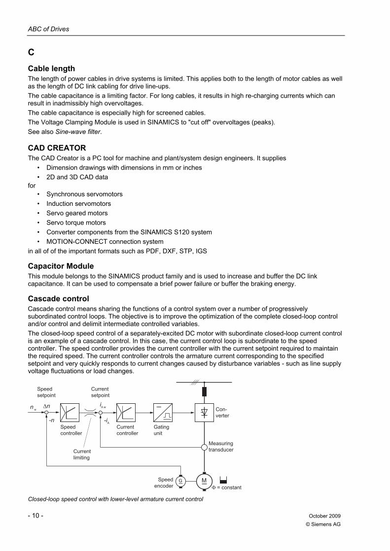
Cascade control Cascade control means sharing the functions of a control system over a number of progressively subordinated control loops. The objective is to improve the optimization of the complete closed-loop control and/or control and delimit intermediate controlled variables. The closed-loop speed control of a separately-excited DC motor with subordinate closed-loop current control is an example of a cascade control. In this case, the current control loop is subordinate to the speed controller. The speed controller provides the current controller with the current setpoint required to maintain the required speed. The current controller controls the armature current corresponding to the specified setpoint and very quickly responds to current changes caused by disturbance variables - such as line supply voltage fluctuations or load changes.
Speed encoder
Gating unit
Current controller
Current setpoint
Speed setpoint
Current limiting
Speed controller
Con-verter
Measuring transducer
G M
wAi
-n
w n _
A-i
Closed-loop speed control with lower-level armature current control
ABC of Drives
October 2009 - 11 - © Siemens AG
Central Braking Module (CBM) The CBM from the SINAMICS product family limits the DC link voltage at a central location in the drive line-up when the motors are regenerating and it is not possible to regenerate into the line supply.
Chassis Converter unit format for higher power ratings mounted on an open frame (chassis) with a low degree of protection for installation in a control cabinet. See also Blocksize and Booksize.
Chopper See DC chopper controller.
Circulating current Circulating current is a DC current that in a double converter only flows through the two partial converters, i.e. not through the load. This is caused by the different instantaneous values of the voltage on the DC side of the partial converters. See also Circulating current reactor, Inverse parallel connection.
Circulating current carrying converter connection Connections with circulating current are connections comprising double-way converters equipped with two partial converters for operation in the four quadrants of the DC current - DC voltage chart; one of these partial converters operates in the rectifier mode and the other in the inverter mode. Current transfer from one partial converter to the other when the torque direction changes is realized without a zero torque interval.
Circulating current reactor Circulating current reactors are used in double converters with circulating current. They are smoothing reactors on the DC side of each of the two partial converters that are simultaneously controlled. These smoothing reactors have the function to limit the circulating current flowing through the two partial converters.
Circulating current-free converter connection A double-way converter in the inverse parallel connection can be operated without any circulating current by only controlling one partial converter while the firing pulses for the second partial converter are blocked. The current transfer from one partial converter to the other when the torque direction changes results in a short zero torque interval. An electronic sequential logic stage is required to detect zero current and subsequently block one of the partial converters and enable the other. See also Inverse parallel connection.
Clock frequency The clock frequency is the frequency used to periodically trigger the arm of a converter circuit. For line-commutated converters this is the frequency of the AC line supply; for load-commutated converters it is a frequency specified from the load, e.g. the rotor position encoder of a synchronous motor. For self-commutated converters, the clock frequency is specified by a control system belonging to the converter unit.
Closed-loop control stability The stability of a closed-loop control system is the maximum remaining, steady-state deviation of the controlled variable (of the actual value) from the set value under the most unfavorable combination of disturbance variables. The deviation is referred to the nominal value of the controlled variable. Temperature changes, changes in the power supply voltage or the load are typical disturbance variables. The dynamic behavior of the control loop can briefly result in additional deviations. For many applications, a good speed stability is far more important than high →Accuracy, e.g. for multi-motor drives with continuous material webs such as is the case for paper and textile machines.
ABC of Drives
- 12 - October 2009 © Siemens AG
Closed-loop position control Closed-loop control structure, which equalizes the difference between the position setpoint and position actual value (see Position controller).
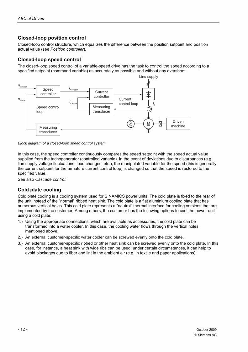
Closed-loop speed control The closed-loop speed control of a variable-speed drive has the task to control the speed according to a specified setpoint (command variable) as accurately as possible and without any overshoot.
Line supply
Speed control loop
Speed controller
actualAiCurrent control loop
setpointAiCurrent
controller
Measuring transducer
Measuring transducer
Driven machine
actual n
setpoint n
i
AI
G M3~
Block diagram of a closed-loop speed control system
In this case, the speed controller continuously compares the speed setpoint with the speed actual value supplied from the tachogenerator (controlled variable). In the event of deviations due to disturbances (e.g. line supply voltage fluctuations, load changes, etc.), the manipulated variable for the speed (this is generally the current setpoint for the armature current control loop) is changed so that the speed is restored to the specified value. See also Cascade control.
Cold plate cooling Cold plate cooling is a cooling system used for SINAMICS power units. The cold plate is fixed to the rear of the unit instead of the "normal" ribbed heat sink. The cold plate is a flat aluminium cooling plate that has numerous vertical holes. This cold plate represents a "neutral" thermal interface for cooling versions that are implemented by the customer. Among others, the customer has the following options to cool the power unit using a cold plate: 1.) Using the appropriate connections, which are available as accessories, the cold plate can be
transformed into a water cooler. In this case, the cooling water flows through the vertical holes mentioned above.
2.) An external customer-specific water cooler can be screwed evenly onto the cold plate. 3.) An external customer-specific ribbed or other heat sink can be screwed evenly onto the cold plate. In this
case, for instance, a heat sink with wide ribs can be used; under certain circumstances, it can help to avoid blockages due to fiber and lint in the ambient air (e.g. in textile and paper applications).
ABC of Drives
October 2009 - 13 - © Siemens AG
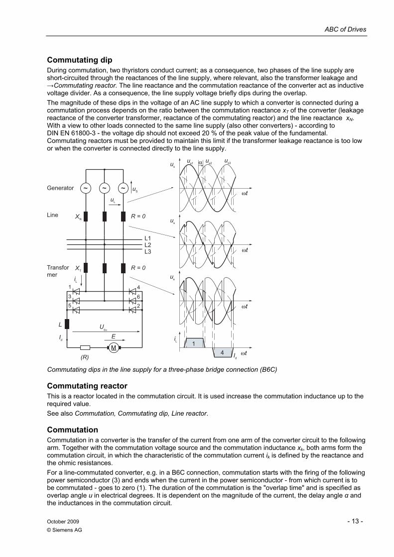
Commutating dip During commutation, two thyristors conduct current; as a consequence, two phases of the line supply are short-circuited through the reactances of the line supply, where relevant, also the transformer leakage and →Commutating reactor. The line reactance and the commutation reactance of the converter act as inductive voltage divider. As a consequence, the line supply voltage briefly dips during the overlap. The magnitude of these dips in the voltage of an AC line supply to which a converter is connected during a commutation process depends on the ratio between the commutation reactance xT of the converter (leakage reactance of the converter transformer, reactance of the commutating reactor) and the line reactance xN. With a view to other loads connected to the same line supply (also other converters) - according to DIN EN 61800-3 - the voltage dip should not exceed 20 % of the peak value of the fundamental. Commutating reactors must be provided to maintain this limit if the transformer leakage reactance is too low or when the converter is connected directly to the line supply.
Transformer
Line
L3L2L1
Generator ~ ~~
NX R = 0
Su
Lu
s3us2us1u
su
su
41
dI
Li
su
TX R = 0
(R)
E
2
6
4
5
3
1Li
L
dI
U
M
Commutating dips in the line supply for a three-phase bridge connection (B6C)
Commutating reactor This is a reactor located in the commutation circuit. It is used increase the commutation inductance up to the required value. See also Commutation, Commutating dip, Line reactor.
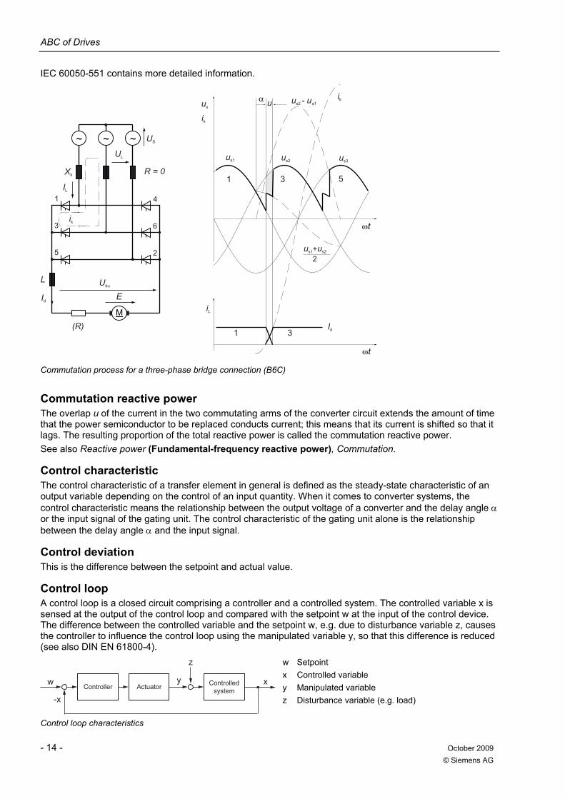
Commutation Commutation in a converter is the transfer of the current from one arm of the converter circuit to the following arm. Together with the commutation voltage source and the commutation inductance xk, both arms form the commutation circuit, in which the characteristic of the commutation current ik is defined by the reactance and the ohmic resistances. For a line-commutated converter, e.g. in a B6C connection, commutation starts with the firing of the following power semiconductor (3) and ends when the current in the power semiconductor - from which current is to be commutated - goes to zero (1). The duration of the commutation is the "overlap time" and is specified as overlap angle u in electrical degrees. It is dependent on the magnitude of the current, the delay angle α and the inductances in the commutation circuit.
ABC of Drives
- 14 - October 2009 © Siemens AG
IEC 60050-551 contains more detailed information.
M
Udα
Id
L
IL
UL
1
3
5
4
6
2
US
us1 us2 us3
ωt
ωt
α u
iL
Id
E
(R)
R = 0
ik
Xk
~ ~~
ik
1 3 5
us2 - us1
us1+us2
2
1 3
ik
us
Commutation process for a three-phase bridge connection (B6C)
Commutation reactive power The overlap u of the current in the two commutating arms of the converter circuit extends the amount of time that the power semiconductor to be replaced conducts current; this means that its current is shifted so that it lags. The resulting proportion of the total reactive power is called the commutation reactive power. See also Reactive power (Fundamental-frequency reactive power), Commutation.
Control characteristic The control characteristic of a transfer element in general is defined as the steady-state characteristic of an output variable depending on the control of an input quantity. When it comes to converter systems, the control characteristic means the relationship between the output voltage of a converter and the delay angle α or the input signal of the gating unit. The control characteristic of the gating unit alone is the relationship between the delay angle α and the input signal.
Control deviation This is the difference between the setpoint and actual value.
Control loop A control loop is a closed circuit comprising a controller and a controlled system. The controlled variable x is sensed at the output of the control loop and compared with the setpoint w at the input of the control device. The difference between the controlled variable and the setpoint w, e.g. due to disturbance variable z, causes the controller to influence the control loop using the manipulated variable y, so that this difference is reduced (see also DIN EN 61800-4).
Controlled systemActuatorController
-x
xw
z
y
w Setpoint x Controlled variable y Manipulated variable z Disturbance variable (e.g. load)
Control loop characteristics
ABC of Drives
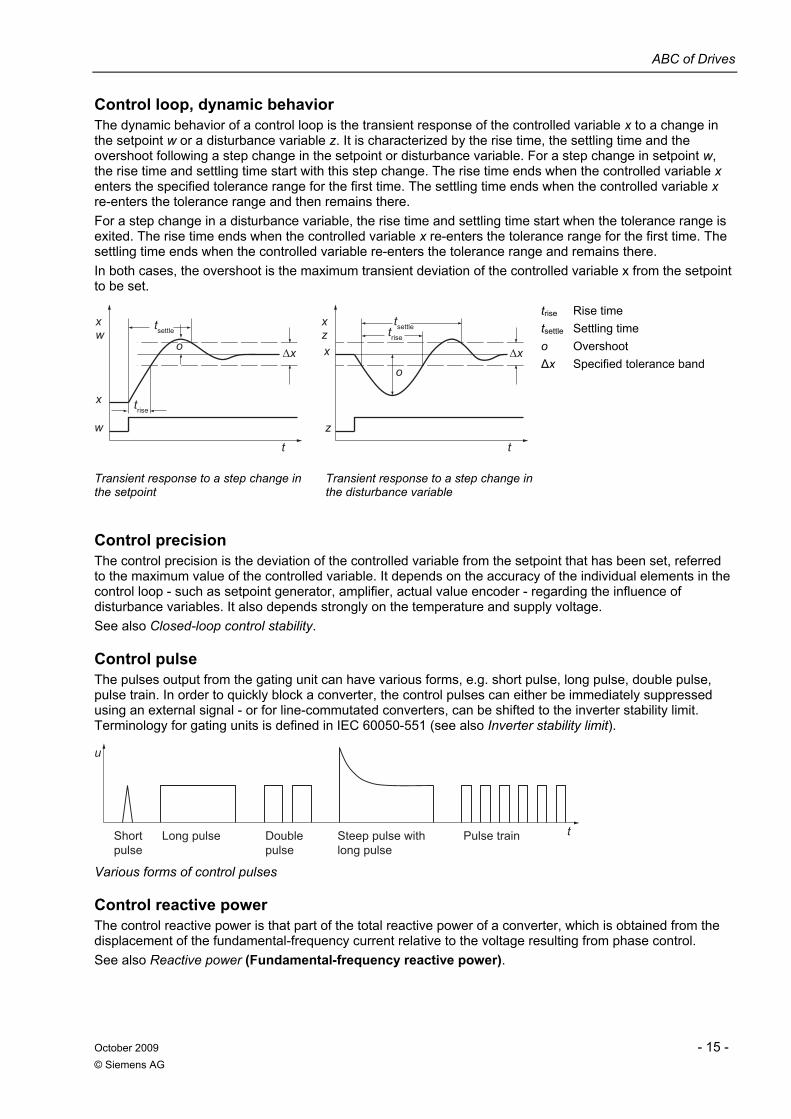
October 2009 - 15 - © Siemens AG
Control loop, dynamic behavior The dynamic behavior of a control loop is the transient response of the controlled variable x to a change in the setpoint w or a disturbance variable z. It is characterized by the rise time, the settling time and the overshoot following a step change in the setpoint or disturbance variable. For a step change in setpoint w, the rise time and settling time start with this step change. The rise time ends when the controlled variable x enters the specified tolerance range for the first time. The settling time ends when the controlled variable x re-enters the tolerance range and then remains there. For a step change in a disturbance variable, the rise time and settling time start when the tolerance range is exited. The rise time ends when the controlled variable x re-enters the tolerance range for the first time. The settling time ends when the controlled variable re-enters the tolerance range and remains there. In both cases, the overshoot is the maximum transient deviation of the controlled variable x from the setpoint to be set.
z
xzx
t
o
w
x
tsettletsettletrise
trise
wx
t
o
trise Rise time tsettle Settling time o Overshoot Δx Specified tolerance band
Transient response to a step change in the setpoint
Transient response to a step change in the disturbance variable
Control precision The control precision is the deviation of the controlled variable from the setpoint that has been set, referred to the maximum value of the controlled variable. It depends on the accuracy of the individual elements in the control loop - such as setpoint generator, amplifier, actual value encoder - regarding the influence of disturbance variables. It also depends strongly on the temperature and supply voltage. See also Closed-loop control stability.
Control pulse The pulses output from the gating unit can have various forms, e.g. short pulse, long pulse, double pulse, pulse train. In order to quickly block a converter, the control pulses can either be immediately suppressed using an external signal - or for line-commutated converters, can be shifted to the inverter stability limit. Terminology for gating units is defined in IEC 60050-551 (see also Inverter stability limit).
Pulse trainSteep pulse with long pulse
Double pulse
Long pulseShort pulse
u
t
Various forms of control pulses
Control reactive power The control reactive power is that part of the total reactive power of a converter, which is obtained from the displacement of the fundamental-frequency current relative to the voltage resulting from phase control. See also Reactive power (Fundamental-frequency reactive power).
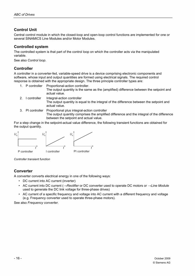
ABC of Drives
- 16 - October 2009 © Siemens AG
Control Unit Central control module in which the closed-loop and open-loop control functions are implemented for one or several SINAMICS Line Modules and/or Motor Modules.
Controlled system The controlled system is that part of the control loop on which the controller acts via the manipulated variable. See also Control loop.
Controller A controller in a converter-fed, variable-speed drive is a device comprising electronic components and software, whose input and output quantities are formed using electrical signals. The required control response is obtained with the appropriate design. The three principle controller types are:
1. P controller Proportional-action controller. The output quantity is the same as the (amplified) difference between the setpoint and actual value.
2. I controller Integral-action controller The output quantity is equal to the integral of the difference between the setpoint and actual value.
3. PI controller Proportional plus integral-action controller The output quantity comprises the amplified difference and the integral of the difference between the setpoint and actual value.
For a step change in the setpoint-actual value difference, the following transient functions are obtained for the output quantity.
PI controllerI controllerP controllert
UA UAUA
tt
Controller transient function
Converter A converter converts electrical energy in one of the following ways:
• DC current into AC current (inverter) • AC current into DC current (→Rectifier or DC converter used to operate DC motors or →Line Module
used to generate the DC link voltage for three-phase drives) • AC current of a specific frequency and voltage into AC current with a different frequency and voltage
(e.g. Frequency converter used to operate three-phase motors). See also Frequency converter.
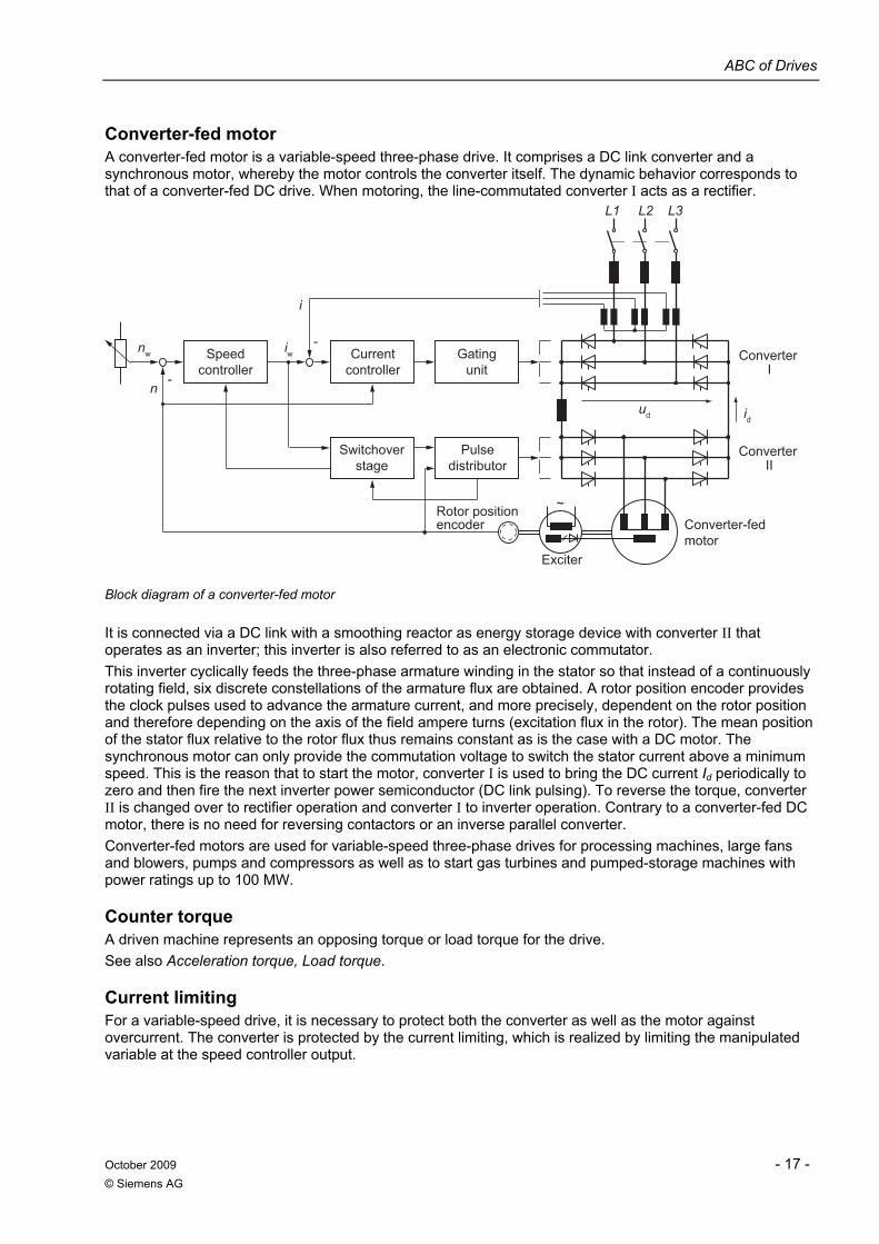
ABC of Drives
October 2009 - 17 - © Siemens AG
Converter-fed motor A converter-fed motor is a variable-speed three-phase drive. It comprises a DC link converter and a synchronous motor, whereby the motor controls the converter itself. The dynamic behavior corresponds to that of a converter-fed DC drive. When motoring, the line-commutated converter I acts as a rectifier.
Converter
Converter
Rotor position encoder
Exciter
Converter-fed motor
Switchover stage
Speed controller
Current controller
Pulse distributor
Gating unit I
II
ud
n-
nw-
L1 L2 L3
i
id
iw
~
Block diagram of a converter-fed motor
It is connected via a DC link with a smoothing reactor as energy storage device with converter II that operates as an inverter; this inverter is also referred to as an electronic commutator. This inverter cyclically feeds the three-phase armature winding in the stator so that instead of a continuously rotating field, six discrete constellations of the armature flux are obtained. A rotor position encoder provides the clock pulses used to advance the armature current, and more precisely, dependent on the rotor position and therefore depending on the axis of the field ampere turns (excitation flux in the rotor). The mean position of the stator flux relative to the rotor flux thus remains constant as is the case with a DC motor. The synchronous motor can only provide the commutation voltage to switch the stator current above a minimum speed. This is the reason that to start the motor, converter I is used to bring the DC current Id periodically to zero and then fire the next inverter power semiconductor (DC link pulsing). To reverse the torque, converter II is changed over to rectifier operation and converter I to inverter operation. Contrary to a converter-fed DC motor, there is no need for reversing contactors or an inverse parallel converter. Converter-fed motors are used for variable-speed three-phase drives for processing machines, large fans and blowers, pumps and compressors as well as to start gas turbines and pumped-storage machines with power ratings up to 100 MW.
Counter torque A driven machine represents an opposing torque or load torque for the drive. See also Acceleration torque, Load torque.
Current limiting For a variable-speed drive, it is necessary to protect both the converter as well as the motor against overcurrent. The converter is protected by the current limiting, which is realized by limiting the manipulated variable at the speed controller output.
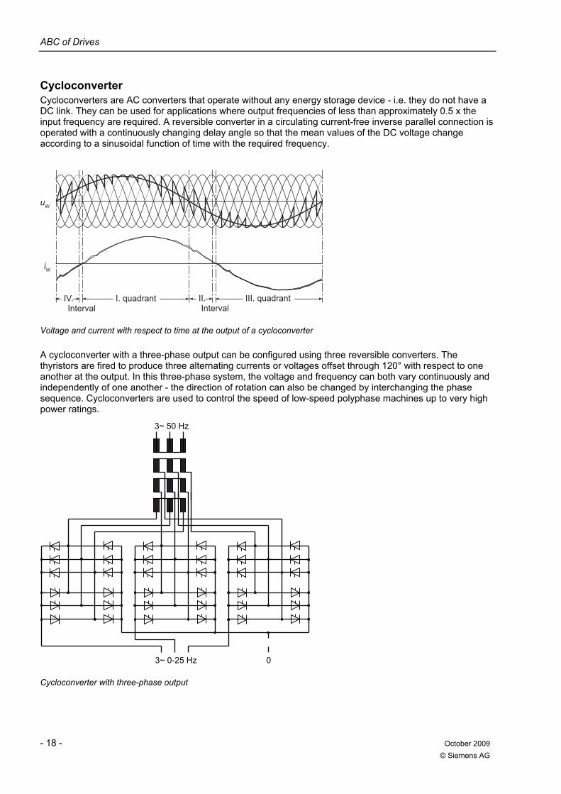
ABC of Drives
- 18 - October 2009 © Siemens AG
Cycloconverter Cycloconverters are AC converters that operate without any energy storage device - i.e. they do not have a DC link. They can be used for applications where output frequencies of less than approximately 0.5 x the input frequency are required. A reversible converter in a circulating current-free inverse parallel connection is operated with a continuously changing delay angle so that the mean values of the DC voltage change according to a sinusoidal function of time with the required frequency.
Interval IntervalIII. quadrantI. quadrantIV. II.
iW
uW
Voltage and current with respect to time at the output of a cycloconverter
A cycloconverter with a three-phase output can be configured using three reversible converters. The thyristors are fired to produce three alternating currents or voltages offset through 120° with respect to one another at the output. In this three-phase system, the voltage and frequency can both vary continuously and independently of one another - the direction of rotation can also be changed by interchanging the phase sequence. Cycloconverters are used to control the speed of low-speed polyphase machines up to very high power ratings.
3~ 0-25 Hz
3~ 50 Hz
0
Cycloconverter with three-phase output
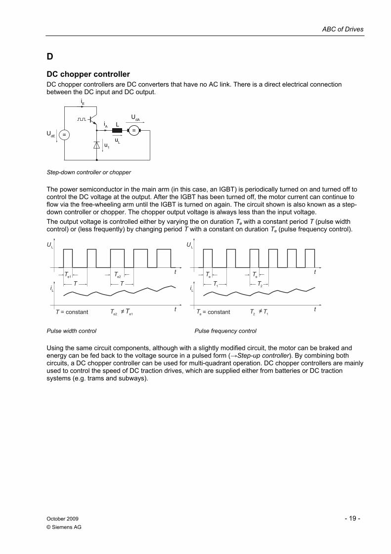
ABC of Drives
October 2009 - 19 - © Siemens AG
D
DC chopper controller DC chopper controllers are DC converters that have no AC link. There is a direct electrical connection between the DC input and DC output.
iE
iAUdA
uLu1
==
LUdE
Step-down controller or chopper
The power semiconductor in the main arm (in this case, an IGBT) is periodically turned on and turned off to control the DC voltage at the output. After the IGBT has been turned off, the motor current can continue to flow via the free-wheeling arm until the IGBT is turned on again. The circuit shown is also known as a step-down controller or chopper. The chopper output voltage is always less than the input voltage. The output voltage is controlled either by varying the on duration Te with a constant period T (pulse width control) or (less frequently) by changing period T with a constant on duration Te (pulse frequency control).
= constantT = constant
2T
1T2T ≠ ≠ eT
Li
t
LU
1T
teT eT
Li
e1T e2T t
LU
TT
te1T e2T
Pulse width control Pulse frequency control
Using the same circuit components, although with a slightly modified circuit, the motor can be braked and energy can be fed back to the voltage source in a pulsed form (→Step-up controller). By combining both circuits, a DC chopper controller can be used for multi-quadrant operation. DC chopper controllers are mainly used to control the speed of DC traction drives, which are supplied either from batteries or DC traction systems (e.g. trams and subways).
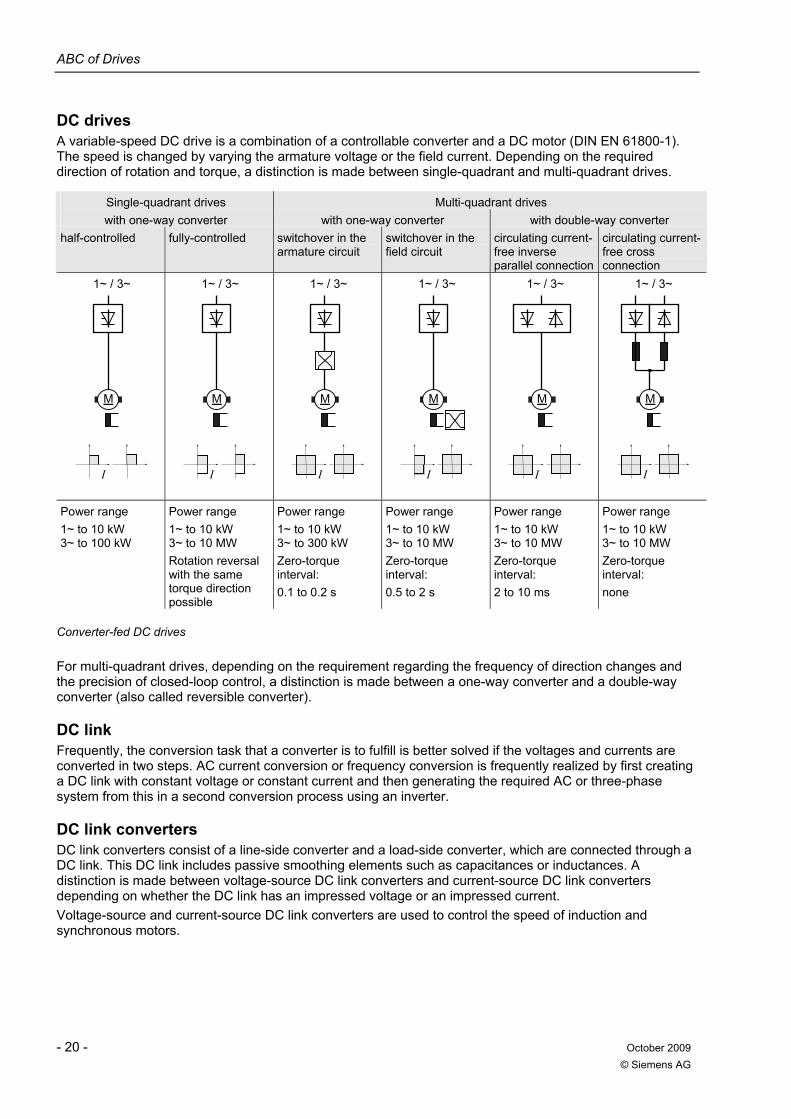
ABC of Drives
- 20 - October 2009 © Siemens AG
DC drives A variable-speed DC drive is a combination of a controllable converter and a DC motor (DIN EN 61800-1). The speed is changed by varying the armature voltage or the field current. Depending on the required direction of rotation and torque, a distinction is made between single-quadrant and multi-quadrant drives.
Single-quadrant drives Multi-quadrant drives with one-way converter with one-way converter with double-way converter
half-controlled fully-controlled switchover in the armature circuit
switchover in the field circuit
circulating current-free inverse parallel connection
circulating current-free cross connection
1~ / 3~
M
I
1~ / 3~
M
I
1~ / 3~
M
I
1~ / 3~
M
I
1~ / 3~
M
I
1~ / 3~
M
I
Power range 1~ to 10 kW 3~ to 100 kW
Power range 1~ to 10 kW 3~ to 10 MW Rotation reversal with the same torque direction possible
Power range 1~ to 10 kW 3~ to 300 kW Zero-torque interval: 0.1 to 0.2 s
Power range 1~ to 10 kW 3~ to 10 MW Zero-torque interval: 0.5 to 2 s
Power range 1~ to 10 kW 3~ to 10 MW Zero-torque interval: 2 to 10 ms
Power range 1~ to 10 kW 3~ to 10 MW Zero-torque interval: none
Converter-fed DC drives
For multi-quadrant drives, depending on the requirement regarding the frequency of direction changes and the precision of closed-loop control, a distinction is made between a one-way converter and a double-way converter (also called reversible converter).
DC link Frequently, the conversion task that a converter is to fulfill is better solved if the voltages and currents are converted in two steps. AC current conversion or frequency conversion is frequently realized by first creating a DC link with constant voltage or constant current and then generating the required AC or three-phase system from this in a second conversion process using an inverter.
DC link converters DC link converters consist of a line-side converter and a load-side converter, which are connected through a DC link. This DC link includes passive smoothing elements such as capacitances or inductances. A distinction is made between voltage-source DC link converters and current-source DC link converters depending on whether the DC link has an impressed voltage or an impressed current. Voltage-source and current-source DC link converters are used to control the speed of induction and synchronous motors.
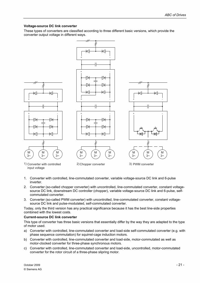
ABC of Drives
October 2009 - 21 - © Siemens AG
Voltage-source DC link converter These types of converters are classified according to three different basic versions, which provide the converter output voltage in different ways.
PWM converterChopper converterConverter with controlled input voltage
3~M
3~M
3~M
3~M
3~M
3~M
3~M
3~M
3~M
3)2)1)
-+
-+-+
-+
-+
-+-+
-+
1. Converter with controlled, line-commutated converter, variable voltage-source DC link and 6-pulse
inverter. 2. Converter (so-called chopper converter) with uncontrolled, line-commutated converter, constant voltage-
source DC link, downstream DC controller (chopper), variable voltage-source DC link and 6-pulse, self-commutated converter.
3. Converter (so-called PWM converter) with uncontrolled, line-commutated converter, constant voltage-source DC link and pulse-modulated, self-commutated converter.
Today, only the third version has any practical significance because it has the best line-side properties combined with the lowest costs. Current-source DC link converter This type of converter has three basic versions that essentially differ by the way they are adapted to the type of motor used. a) Converter with controlled, line-commutated converter and load-side self-commutated converter (e.g. with
phase sequence commutation) for squirrel-cage induction motors. b) Converter with controlled, line-commutated converter and load-side, motor-commutated as well as
motor-clocked converter for three-phase synchronous motors. c) Converter with controlled, line-commutated converter and load-side, uncontrolled, motor-commutated
converter for the rotor circuit of a three-phase slipring motor.
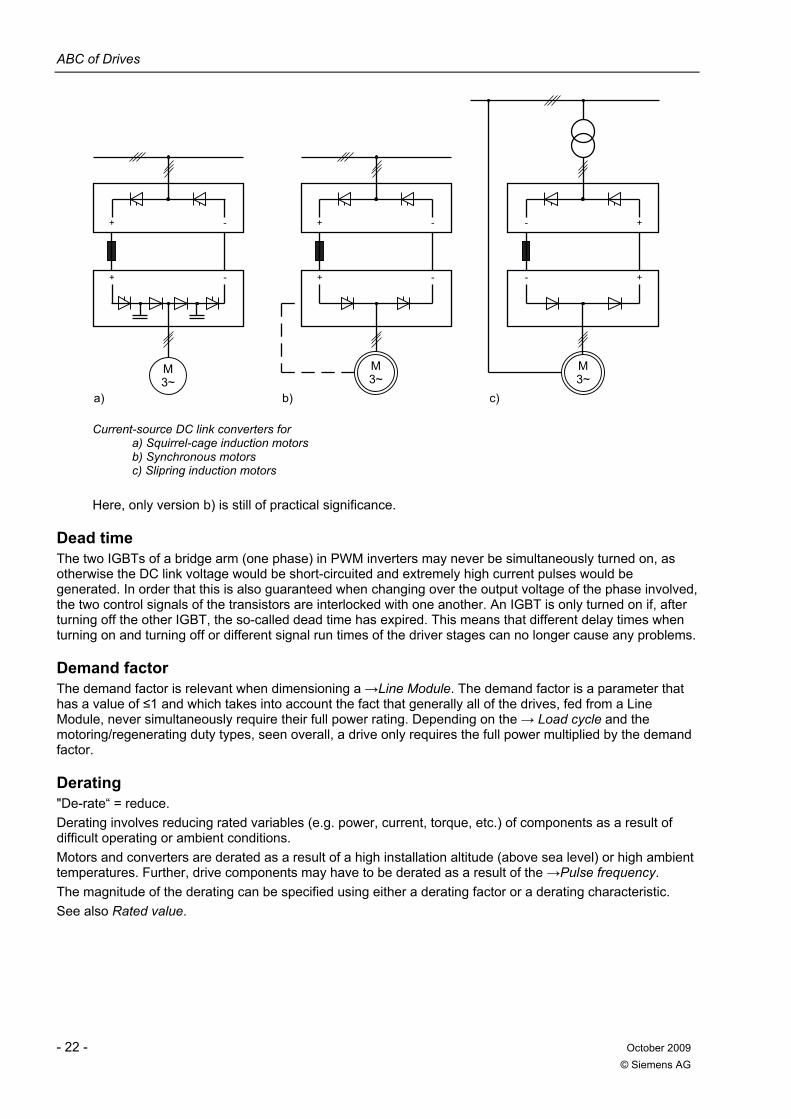
ABC of Drives
- 22 - October 2009 © Siemens AG
+ -
+ -
M3~
+ -
+ -
- +
- +
a) b) c)
M3~
M3~
Current-source DC link converters for a) Squirrel-cage induction motors b) Synchronous motors c) Slipring induction motors
Here, only version b) is still of practical significance.
Dead time The two IGBTs of a bridge arm (one phase) in PWM inverters may never be simultaneously turned on, as otherwise the DC link voltage would be short-circuited and extremely high current pulses would be generated. In order that this is also guaranteed when changing over the output voltage of the phase involved, the two control signals of the transistors are interlocked with one another. An IGBT is only turned on if, after turning off the other IGBT, the so-called dead time has expired. This means that different delay times when turning on and turning off or different signal run times of the driver stages can no longer cause any problems.
Demand factor The demand factor is relevant when dimensioning a →Line Module. The demand factor is a parameter that has a value of ≤1 and which takes into account the fact that generally all of the drives, fed from a Line Module, never simultaneously require their full power rating. Depending on the → Load cycle and the motoring/regenerating duty types, seen overall, a drive only requires the full power multiplied by the demand factor.
Derating "De-rate“ = reduce. Derating involves reducing rated variables (e.g. power, current, torque, etc.) of components as a result of difficult operating or ambient conditions. Motors and converters are derated as a result of a high installation altitude (above sea level) or high ambient temperatures. Further, drive components may have to be derated as a result of the →Pulse frequency. The magnitude of the derating can be specified using either a derating factor or a derating characteristic. See also Rated value.
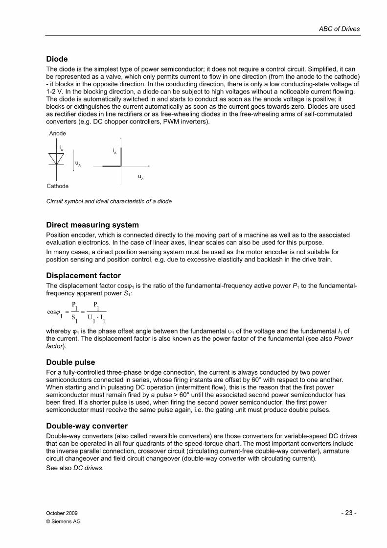
ABC of Drives
October 2009 - 23 - © Siemens AG
Diode The diode is the simplest type of power semiconductor; it does not require a control circuit. Simplified, it can be represented as a valve, which only permits current to flow in one direction (from the anode to the cathode) - it blocks in the opposite direction. In the conducting direction, there is only a low conducting-state voltage of 1-2 V. In the blocking direction, a diode can be subject to high voltages without a noticeable current flowing. The diode is automatically switched in and starts to conduct as soon as the anode voltage is positive; it blocks or extinguishes the current automatically as soon as the current goes towards zero. Diodes are used as rectifier diodes in line rectifiers or as free-wheeling diodes in the free-wheeling arms of self-commutated converters (e.g. DC chopper controllers, PWM inverters).
Cathode
Anode
iAiA
uA
uA
Circuit symbol and ideal characteristic of a diode
Direct measuring system Position encoder, which is connected directly to the moving part of a machine as well as to the associated evaluation electronics. In the case of linear axes, linear scales can also be used for this purpose. In many cases, a direct position sensing system must be used as the motor encoder is not suitable for position sensing and position control, e.g. due to excessive elasticity and backlash in the drive train.
Displacement factor The displacement factor cosφ1 is the ratio of the fundamental-frequency active power P1 to the fundamental-frequency apparent power S1:
1I1U1P
1S1P
1cos
⋅==ϕ
whereby φ1 is the phase offset angle between the fundamental υ1 of the voltage and the fundamental I1 of the current. The displacement factor is also known as the power factor of the fundamental (see also Power factor).
Double pulse For a fully-controlled three-phase bridge connection, the current is always conducted by two power semiconductors connected in series, whose firing instants are offset by 60° with respect to one another. When starting and in pulsating DC operation (intermittent flow), this is the reason that the first power semiconductor must remain fired by a pulse > 60° until the associated second power semiconductor has been fired. If a shorter pulse is used, when firing the second power semiconductor, the first power semiconductor must receive the same pulse again, i.e. the gating unit must produce double pulses.
Double-way converter Double-way converters (also called reversible converters) are those converters for variable-speed DC drives that can be operated in all four quadrants of the speed-torque chart. The most important converters include the inverse parallel connection, crossover circuit (circulating current-free double-way converter), armature circuit changeover and field circuit changeover (double-way converter with circulating current). See also DC drives.
ABC of Drives
- 24 - October 2009 © Siemens AG
Drive Control Chart (DCC) DCC is an add-on for the STARTER commissioning tool. It extends the possibilities of configuring technological functions for SINAMICS drives in an extremely easy way. The user-friendly DCC editor allows a user-friendly configuration, the transparent representation of control structures and the reuse of diagrams that have already been created. The block library contains a large selection of control, arithmetic and logic blocks as well as extensive open-loop and closed-loop control functions. See also SIZER, STARTER.
Drive efficiency The drive efficiency is obtained from the active power that is output Pout and the active power that is fed in Pin
Poutη 100 %Pin
= ⋅
The power that is fed in comprises the power that is output and the losses PV. Poutη 100 %
P Pout V= ⋅
+
For a converter-fed drive, all of the losses of the drive system must be taken into account (transformer, converter, smoothing device, motor, connecting cables, switchgear).
Drive line-up For SINAMICS, a drive line-up comprises a →Control Unit as well as the →Motor Modules and →Line Modules connected to it via →Drive-CLiQ cables. Under certain circumstances, additional line-side components and DC link components can also be included in the line-up.
Drive/drive system A drive system defines all of the components that are required to implement a drive task. For instance, a drive system can comprise line-side switchgear, converter transformer, converter, output filter, motor, encoder, conductors and cables, monitoring devices, open-loop and closed-loop control devices. A drive system belonging to the SINAMICS product family includes e.g. →Line Modules, →Motor Modules, →Encoders, Motors, Terminal Modules and Sensor Modules as well as supplementary components such as reactors, filters, cables, etc. The closed-loop control module (Control Unit) is connected to the system components through DRIVE-CLiQ cables.
Drive-CLiQ Abbreviation for Drive Component Link with IQ. This involves a communication system for SINAMICS drives which is used to connect the various drive components. These include for instance Control Units, Line Modules, Motor Modules, motors and speed/position encoders. The DRIVE-CLiQ hardware is based on the Industrial Ethernet standard and uses twisted-pair lines. In addition to the send and receive signals, the +24 V power supply is also made available via the DRIVE-CLiQ cable.
Driver stage For controllable power semiconductors, the driver stage is used to provide the gate voltages and currents. At the input, the required switching state of the power semiconductor is transferred using logical signals, e.g. via optocoupler or fiber-optic cable; an isolated power supply is used for this purpose. As a consequence, the driver stage is used as an interface between the (generally digital) control and power semiconductors.
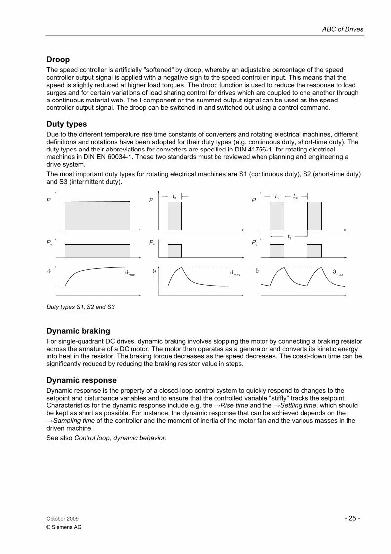
ABC of Drives
October 2009 - 25 - © Siemens AG
Droop The speed controller is artificially "softened" by droop, whereby an adjustable percentage of the speed controller output signal is applied with a negative sign to the speed controller input. This means that the speed is slightly reduced at higher load torques. The droop function is used to reduce the response to load surges and for certain variations of load sharing control for drives which are coupled to one another through a continuous material web. The I component or the summed output signal can be used as the speed controller output signal. The droop can be switched in and switched out using a control command.
Duty types Due to the different temperature rise time constants of converters and rotating electrical machines, different definitions and notations have been adopted for their duty types (e.g. continuous duty, short-time duty). The duty types and their abbreviations for converters are specified in DIN 41756-1, for rotating electrical machines in DIN EN 60034-1. These two standards must be reviewed when planning and engineering a drive system. The most important duty types for rotating electrical machines are S1 (continuous duty), S2 (short-time duty) and S3 (intermittent duty).
tBP
ϑ ϑmaxϑ ϑmax
ϑ ϑmax
Pv Pv Pv
tS
tB tStP P
Duty types S1, S2 and S3
Dynamic braking For single-quadrant DC drives, dynamic braking involves stopping the motor by connecting a braking resistor across the armature of a DC motor. The motor then operates as a generator and converts its kinetic energy into heat in the resistor. The braking torque decreases as the speed decreases. The coast-down time can be significantly reduced by reducing the braking resistor value in steps.
Dynamic response Dynamic response is the property of a closed-loop control system to quickly respond to changes to the setpoint and disturbance variables and to ensure that the controlled variable "stiffly" tracks the setpoint. Characteristics for the dynamic response include e.g. the →Rise time and the →Settling time, which should be kept as short as possible. For instance, the dynamic response that can be achieved depends on the →Sampling time of the controller and the moment of inertia of the motor fan and the various masses in the driven machine. See also Control loop, dynamic behavior.
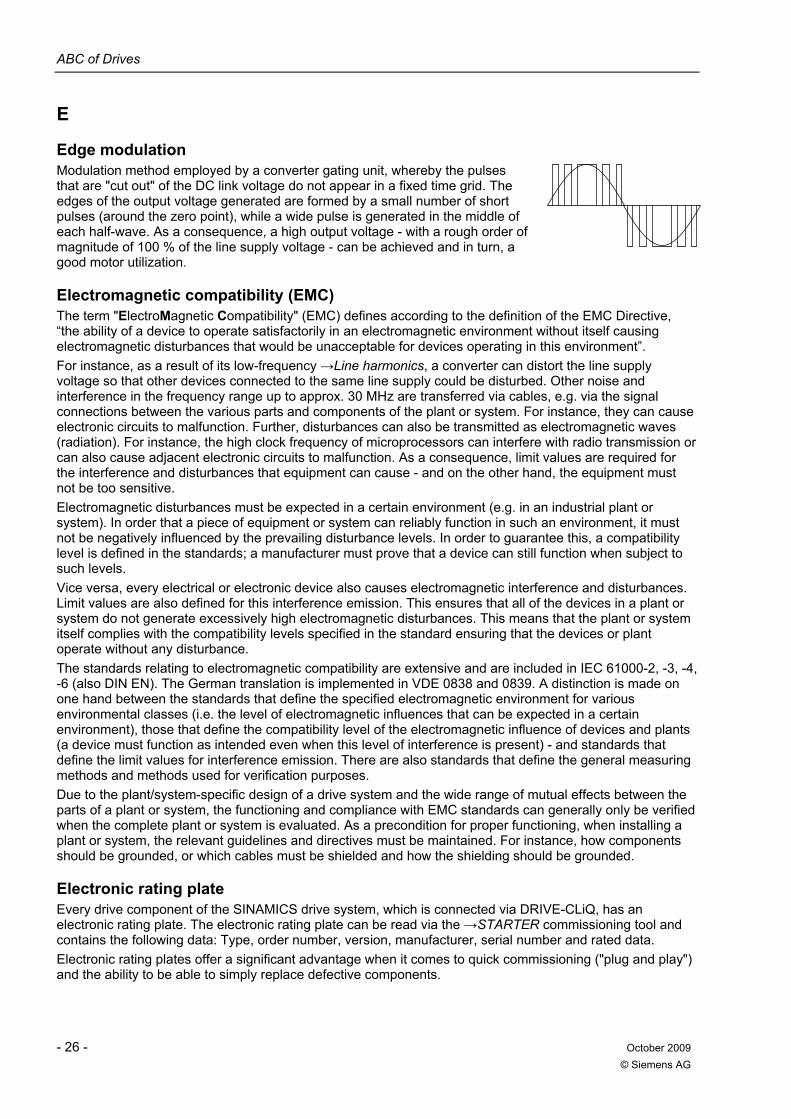
ABC of Drives
- 26 - October 2009 © Siemens AG
E
Edge modulation Modulation method employed by a converter gating unit, whereby the pulses that are "cut out" of the DC link voltage do not appear in a fixed time grid. The edges of the output voltage generated are formed by a small number of short pulses (around the zero point), while a wide pulse is generated in the middle of each half-wave. As a consequence, a high output voltage - with a rough order of magnitude of 100 % of the line supply voltage - can be achieved and in turn, a good motor utilization.
Electromagnetic compatibility (EMC) The term "ElectroMagnetic Compatibility" (EMC) defines according to the definition of the EMC Directive, “the ability of a device to operate satisfactorily in an electromagnetic environment without itself causing electromagnetic disturbances that would be unacceptable for devices operating in this environment”. For instance, as a result of its low-frequency →Line harmonics, a converter can distort the line supply voltage so that other devices connected to the same line supply could be disturbed. Other noise and interference in the frequency range up to approx. 30 MHz are transferred via cables, e.g. via the signal connections between the various parts and components of the plant or system. For instance, they can cause electronic circuits to malfunction. Further, disturbances can also be transmitted as electromagnetic waves (radiation). For instance, the high clock frequency of microprocessors can interfere with radio transmission or can also cause adjacent electronic circuits to malfunction. As a consequence, limit values are required for the interference and disturbances that equipment can cause - and on the other hand, the equipment must not be too sensitive. Electromagnetic disturbances must be expected in a certain environment (e.g. in an industrial plant or system). In order that a piece of equipment or system can reliably function in such an environment, it must not be negatively influenced by the prevailing disturbance levels. In order to guarantee this, a compatibility level is defined in the standards; a manufacturer must prove that a device can still function when subject to such levels. Vice versa, every electrical or electronic device also causes electromagnetic interference and disturbances. Limit values are also defined for this interference emission. This ensures that all of the devices in a plant or system do not generate excessively high electromagnetic disturbances. This means that the plant or system itself complies with the compatibility levels specified in the standard ensuring that the devices or plant operate without any disturbance. The standards relating to electromagnetic compatibility are extensive and are included in IEC 61000-2, -3, -4, -6 (also DIN EN). The German translation is implemented in VDE 0838 and 0839. A distinction is made on one hand between the standards that define the specified electromagnetic environment for various environmental classes (i.e. the level of electromagnetic influences that can be expected in a certain environment), those that define the compatibility level of the electromagnetic influence of devices and plants (a device must function as intended even when this level of interference is present) - and standards that define the limit values for interference emission. There are also standards that define the general measuring methods and methods used for verification purposes. Due to the plant/system-specific design of a drive system and the wide range of mutual effects between the parts of a plant or system, the functioning and compliance with EMC standards can generally only be verified when the complete plant or system is evaluated. As a precondition for proper functioning, when installing a plant or system, the relevant guidelines and directives must be maintained. For instance, how components should be grounded, or which cables must be shielded and how the shielding should be grounded.
Electronic rating plate Every drive component of the SINAMICS drive system, which is connected via DRIVE-CLiQ, has an electronic rating plate. The electronic rating plate can be read via the →STARTER commissioning tool and contains the following data: Type, order number, version, manufacturer, serial number and rated data. Electronic rating plates offer a significant advantage when it comes to quick commissioning ("plug and play") and the ability to be able to simply replace defective components.
ABC of Drives
October 2009 - 27 - © Siemens AG
Encoder An encoder is a measuring system that senses actual speed and/or angular/position values and makes them available for electronic processing. Depending on their mechanical design, encoders can be incorporated in the motor (→Motor encoder) or mounted on the external mechanical system (→External encoder). Depending on the type of movement, a distinction is made between rotary encoders and translatory encoders (e.g. linear scales). In terms of measured value processing, a distinction is made between →Absolute encoders (coded encoders) and incremental encoders. For absolute encoders, a further distinction is made according to the resolution of one revolution and according to the number of absolute revolutions that can be resolved (multiturn encoder). Incremental encoders are also available with different resolutions for one revolution (pulse number). Most versions also allow the direction of rotation to be sensed. So-called raw signal encoders do not provide digital signals, but analog signals that are close to being sinusoidal. These can be "interpolated" in an internal converter evaluation electronics to provide a more accurate resolution. See also External encoder, Incremental encoder, Absolute encoder.
Energy recovery See Regenerative feedback.
External encoder Position encoder that is not integrated or mounted on the motor, but is attached to the driven machine or is driven through an intermediate mechanical element. An external encoder is used to directly detect the position (→Direct measuring system).
Externally-commutated converter The current in one arm of a converter circuit equipped with thyristors changes to the following arm - i.e. it commutates - as a result of the commutation voltage which is effective in the commutation circuit formed by the two power semiconductor arms. The commutation voltage is the quantity that commutates the converter. In the case of externally-commutated converters, the commutation voltage is supplied from an AC voltage source that is separate from the converter. Externally-commutated converters can either be line-commutated or load-commutated. For line-commutated converters, the AC power supply system provides the commutation voltage; for load-commutated converters, it is provided by the load, e.g. the synchronous motor. See also Commutation.
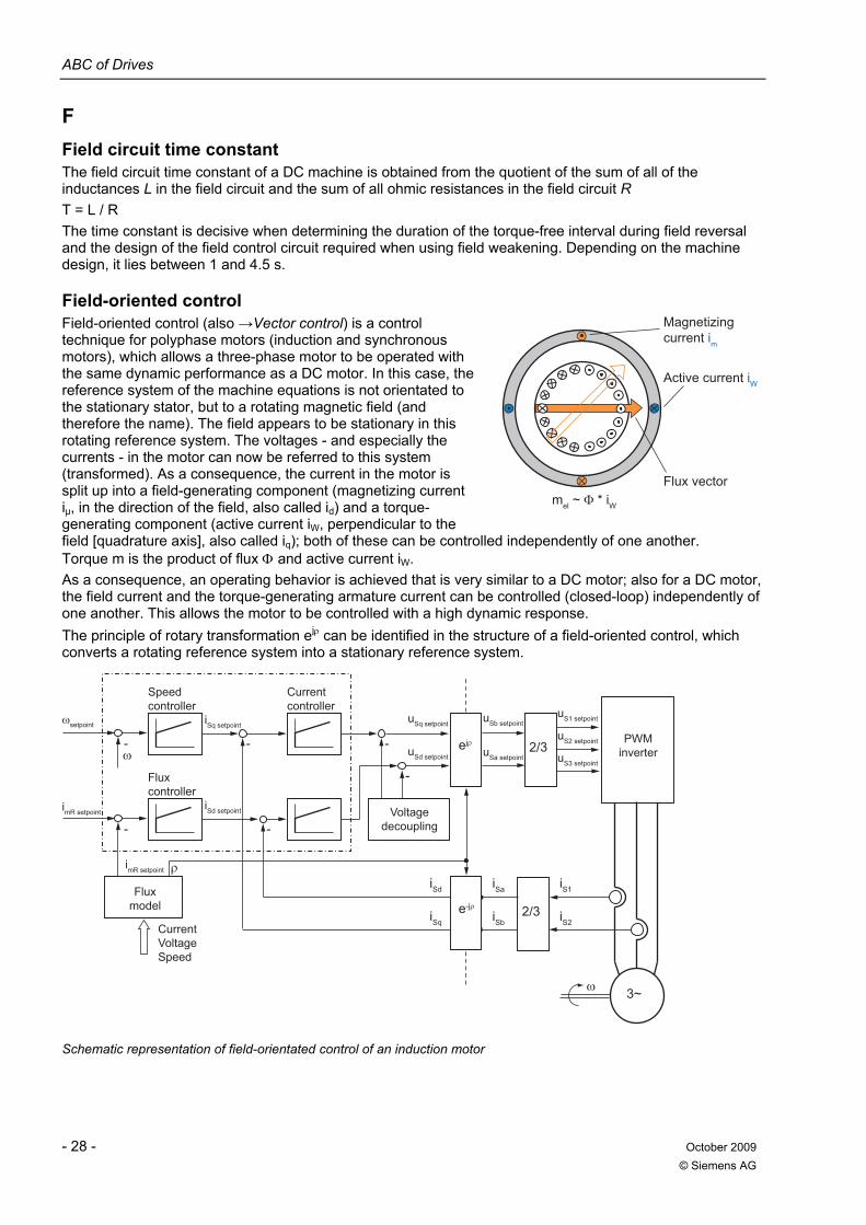
ABC of Drives
- 28 - October 2009 © Siemens AG
F Field circuit time constant The field circuit time constant of a DC machine is obtained from the quotient of the sum of all of the inductances L in the field circuit and the sum of all ohmic resistances in the field circuit R T = L / R The time constant is decisive when determining the duration of the torque-free interval during field reversal and the design of the field control circuit required when using field weakening. Depending on the machine design, it lies between 1 and 4.5 s.
Field-oriented control Field-oriented control (also →Vector control) is a control technique for polyphase motors (induction and synchronous motors), which allows a three-phase motor to be operated with the same dynamic performance as a DC motor. In this case, the reference system of the machine equations is not orientated to the stationary stator, but to a rotating magnetic field (and therefore the name). The field appears to be stationary in this rotating reference system. The voltages - and especially the currents - in the motor can now be referred to this system (transformed). As a consequence, the current in the motor is split up into a field-generating component (magnetizing current iµ, in the direction of the field, also called id) and a torque-generating component (active current iW, perpendicular to the field [quadrature axis], also called iq); both of these can be controlled independently of one another. Torque m is the product of flux Φ and active current iW. As a consequence, an operating behavior is achieved that is very similar to a DC motor; also for a DC motor, the field current and the torque-generating armature current can be controlled (closed-loop) independently of one another. This allows the motor to be controlled with a high dynamic response. The principle of rotary transformation ejρ can be identified in the structure of a field-oriented control, which converts a rotating reference system into a stationary reference system.
uS2 setpoint
uS1 setpoint
uS3 setpoint
uSb setpoint
uSa setpoint
uSq setpoint
uSd setpoint
PWM inverter
Voltage decoupling
iSd setpoint
imR setpoint
imR setpoint
Flux model
CurrentVoltageSpeed
Flux controller
iSq setpoint
Current controller
Speed controller
3~
iSd
iSq2/3
iS1
iS2
iSa
iSb
2/3
- -
-
-- -
Schematic representation of field-orientated control of an induction motor
Active current iW
Magnetizing current im
Flux vector
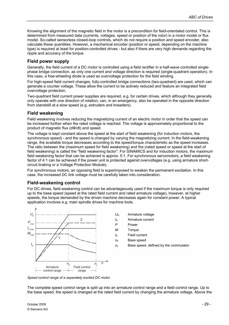
ABC of Drives
October 2009 - 29 - © Siemens AG
Knowing the alignment of the magnetic field in the motor is a precondition for field-orientated control. This is determined from measured data (currents, voltages, speed or position of the rotor) in a motor model or flux model. So-called sensorless closed-loop controls, which do not require a position and speed encoder, also calculate these quantities. However, a mechanical encoder (position or speed, depending on the machine type) is required at least for position-controlled drives - but also if there are very high demands regarding the ripple and accuracy of the torque.
Field power supply Generally, the field current of a DC motor is controlled using a field rectifier in a half-wave controlled single-phase bridge connection, as only one current and voltage direction is required (single-quadrant operation). In this case, a free-wheeling diode is used as overvoltage protection for the field winding. For high-speed field current changes, fully-controlled bridge connections (two-quadrant) are used, which can generate a counter voltage. These allow the current to be actively reduced and feature an integrated field overvoltage protection. Two-quadrant field current power supplies are required, e.g. for certain drives, which although they generally only operate with one direction of rotation, can, in an emergency, also be operated in the opposite direction from standstill at a slow speed (e.g. extruders and kneaders).
Field weakening Field weakening involves reducing the magnetizing current of an electric motor in order that the speed can be increased further when the rated voltage is reached. The voltage is approximately proportional to the product of magnetic flux (dΦ/dt) and speed. The voltage is kept constant above the speed at the start of field weakening (for induction motors, the synchronous speed) - and the speed is changed by varying the magnetizing current. In the field-weakening range, the available torque decreases according to the speed/torque characteristic as the speed increases. The ratio between the (maximum speed for field weakening) and the (rated speed or speed at the start of field weakening) is called the "field weakening factor". For SINAMICS and for induction motors, the maximum field weakening factor that can be achieved is approx. 5:1. For synchronous servomotors, a field weakening factor of 4:1 can be achieved if the power unit is protected against overvoltages (e.g. using armature short-circuit braking or a Voltage Protection Module). For synchronous motors, an opposing field is superimposed to weaken the permanent excitation. In this case, the increased DC link voltage must be carefully taken into consideration.
Field-weakening control For DC drives, field-weakening control can be advantageously used if the maximum torque is only required up to the base speed (speed at the rated field current and rated armature voltage), however, at higher speeds, the torque demanded by the driven machine decreases again for constant power. A typical application involves e.g. main spindle drives for machine tools.
Armature control range
Field control range
nb
1
IE
Mmax
IA max
Pmax
ncn
UA
2
UA Armature voltage IA Armature current P Power M Torque IE Field current nb Base speed nc Base speed, defined by the commutator
Speed control range of a separately excited DC motor
The complete speed control range is split up into an armature control range and a field control range. Up to the base speed, the speed is changed at the rated field current by changing the armature voltage. Above the
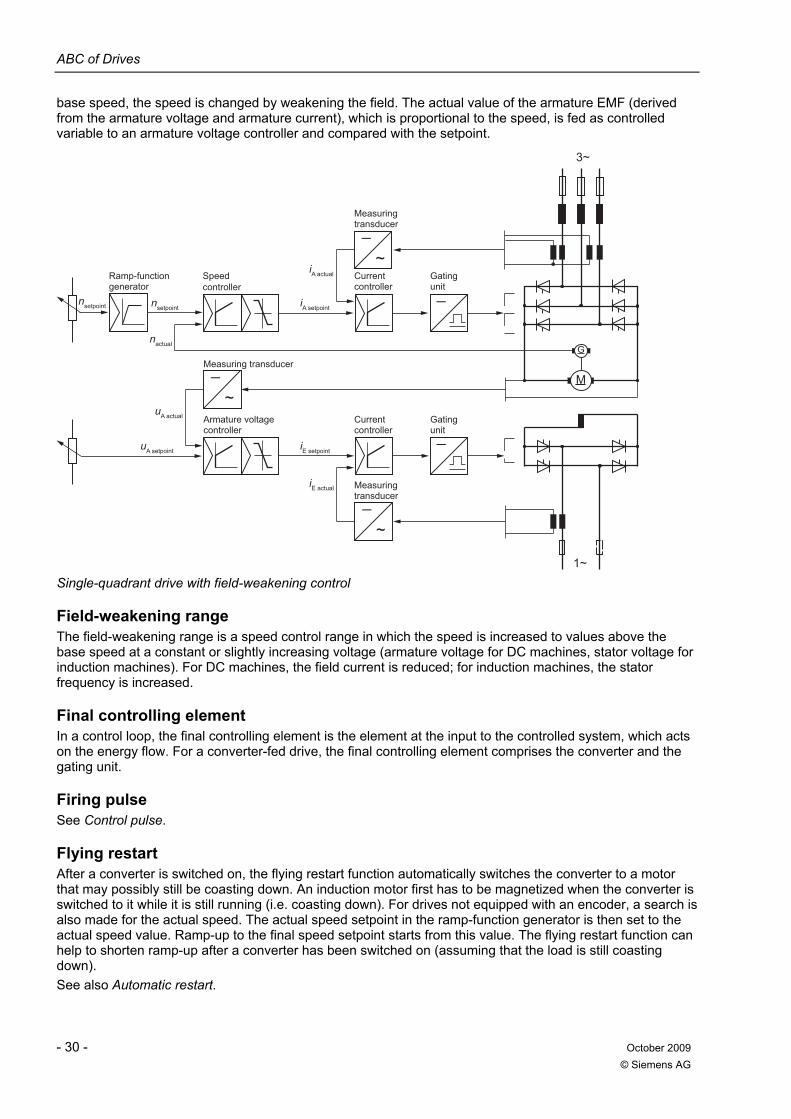
ABC of Drives
- 30 - October 2009 © Siemens AG
base speed, the speed is changed by weakening the field. The actual value of the armature EMF (derived from the armature voltage and armature current), which is proportional to the speed, is fed as controlled variable to an armature voltage controller and compared with the setpoint.
Armature voltage controller
Measuring transducer
nactual
uA actual
uA setpoint
iE actual
iE setpoint
iA actual
iA setpointnsetpointnsetpoint
Ramp-functiongenerator
Speed controller
Measuring transducer
Measuring transducer
Gating unit
Current controller
Gating unit
Current controller
_
~
1~
_
_
~
3~
G
M
_
_
~
Single-quadrant drive with field-weakening control
Field-weakening range The field-weakening range is a speed control range in which the speed is increased to values above the base speed at a constant or slightly increasing voltage (armature voltage for DC machines, stator voltage for induction machines). For DC machines, the field current is reduced; for induction machines, the stator frequency is increased.
Final controlling element In a control loop, the final controlling element is the element at the input to the controlled system, which acts on the energy flow. For a converter-fed drive, the final controlling element comprises the converter and the gating unit.
Firing pulse See Control pulse.
Flying restart After a converter is switched on, the flying restart function automatically switches the converter to a motor that may possibly still be coasting down. An induction motor first has to be magnetized when the converter is switched to it while it is still running (i.e. coasting down). For drives not equipped with an encoder, a search is also made for the actual speed. The actual speed setpoint in the ramp-function generator is then set to the actual speed value. Ramp-up to the final speed setpoint starts from this value. The flying restart function can help to shorten ramp-up after a converter has been switched on (assuming that the load is still coasting down). See also Automatic restart.
ABC of Drives
October 2009 - 31 - © Siemens AG
Four-quadrant operation A four-quadrant drive can be operated in all four quadrants of the speed-torque chart (→Multi-quadrant drive). It can operate in both directions of rotation in the driving (motoring) as well as the braking (regenerative) modes. When braking, the mechanical power that is generated is converted into electric power and fed back into the source (this is generally the line supply).
Free function blocks Software functions of a SINAMICS converter used to logically combine states and commands and to perform arithmetic operations to control a drive system.
Free-wheeling arm A free-wheeling arm is an auxiliary arm of a converter circuit comprising an uncontrolled power semiconductor - the free-wheeling rectifier. Its forward direction, viewed from the load side, corresponds to the forward direction of the associated main arms. This arm can always conduct current if its anode is positive with respect to the cathode. An example is the free-wheeling arm of a →DC chopper controller.
Free-wheeling current The free-wheeling current is the current that flows through the free-wheeling arm of a converter circuit. It is dependent on the control factor. See also Free-wheeling arm.
Free-wheeling rectifier The free-wheeling rectifier is a diode located in the free-wheeling arm. It was previously also known as the zero anode. See also Free-wheeling arm.
Frequency converter Frequency converters are electronic devices that generate a three-phase system with varying frequency and voltage from the three-phase or AC line supply. This three-phase system is used to vary the speed of three-phase motors. They comprise (exception: cycloconverter) a line-side converter, a DC link and a motor-side inverter. A distinction is made between voltage-source DC link converters (impressed voltage with smoothing capacitors) and current-source DC link converters (impressed current with smoothing reactors).
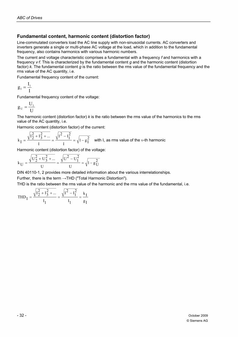
ABC of Drives
- 32 - October 2009 © Siemens AG
Fundamental content, harmonic content (distortion factor) Line-commutated converters load the AC line supply with non-sinusoidal currents. AC converters and inverters generate a single or multi-phase AC voltage at the load, which in addition to the fundamental frequency, also contains harmonics with various harmonic numbers. The current and voltage characteristic comprises a fundamental with a frequency f and harmonics with a frequency ν·f. This is characterized by the fundamental content g and the harmonic content (distortion factor) k. The fundamental content g is the ratio between the rms value of the fundamental frequency and the rms value of the AC quantity, i.e. Fundamental frequency content of the current:
IIg 1
I =
Fundamental frequency content of the voltage:
UUg 1
U =
The harmonic content (distortion factor) k is the ratio between the rms value of the harmonics to the rms value of the AC quantity, i.e. Harmonic content (distortion factor) of the current:
2Ig1
I
21I
2I
I
...23I2
2IIk −=
−=
++= with Iν as rms value of the ν-th harmonic
Harmonic content (distortion factor) of the voltage:
2Ug1
U
21U2U
U
...23U2
2UUk −=
−=
++=
DIN 40110-1, 2 provides more detailed information about the various interrelationships. Further, there is the term →THD ("Total Harmonic Distortion"). THD is the ratio between the rms value of the harmonic and the rms value of the fundamental, i.e.
IgIk
1I
21I
2I
1I
...23I2
2IITHD =
−=
++=
ABC of Drives
October 2009 - 33 - © Siemens AG
G
Gating unit The gating unit belongs to the basic equipment of a converter. It is used to control the energy flow by firing or turning off the controllable power semiconductors at specified instants in time. For line-commutated converters, these firing times are defined by delay angle α specified in electrical degrees. The control range of a gating unit is the range in which the delay angle α can be varied, starting from the zero delay angle setting (α = 0) by varying the input voltage of the gating unit.
Group drive With group drives, several motors are connected to one →Converter. The motors can either be induction motors or synchronous motors (e.g. SIEMOSYN motors for applications in the textile industry). Normally, the connected motors must be the same; however for →V/f control, this is not absolutely necessary.
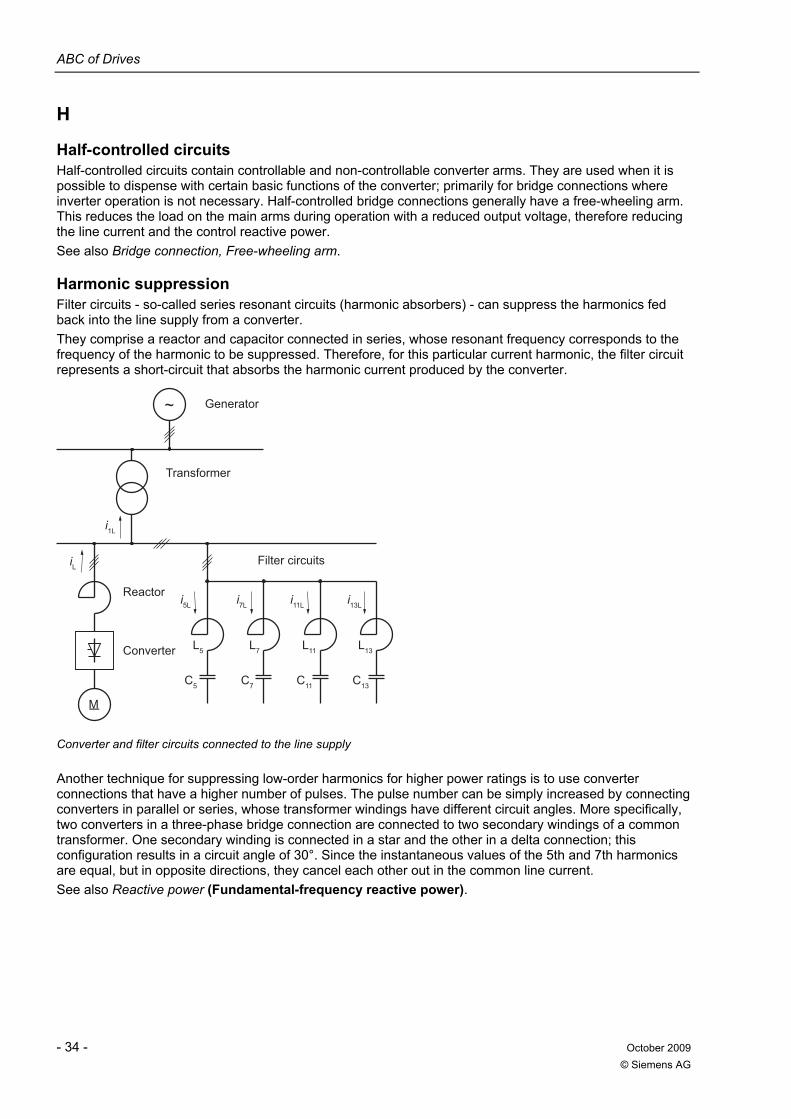
ABC of Drives
- 34 - October 2009 © Siemens AG
H
Half-controlled circuits Half-controlled circuits contain controllable and non-controllable converter arms. They are used when it is possible to dispense with certain basic functions of the converter; primarily for bridge connections where inverter operation is not necessary. Half-controlled bridge connections generally have a free-wheeling arm. This reduces the load on the main arms during operation with a reduced output voltage, therefore reducing the line current and the control reactive power. See also Bridge connection, Free-wheeling arm.
Harmonic suppression Filter circuits - so-called series resonant circuits (harmonic absorbers) - can suppress the harmonics fed back into the line supply from a converter. They comprise a reactor and capacitor connected in series, whose resonant frequency corresponds to the frequency of the harmonic to be suppressed. Therefore, for this particular current harmonic, the filter circuit represents a short-circuit that absorbs the harmonic current produced by the converter.
Filter circuits
Reactor
Transformer
Generator
Converter
i5L i7L i11L i13L
C13C11C7C5
L13L11L7L5
iL
i1L
~
M
Converter and filter circuits connected to the line supply
Another technique for suppressing low-order harmonics for higher power ratings is to use converter connections that have a higher number of pulses. The pulse number can be simply increased by connecting converters in parallel or series, whose transformer windings have different circuit angles. More specifically, two converters in a three-phase bridge connection are connected to two secondary windings of a common transformer. One secondary winding is connected in a star and the other in a delta connection; this configuration results in a circuit angle of 30°. Since the instantaneous values of the 5th and 7th harmonics are equal, but in opposite directions, they cancel each other out in the common line current. See also Reactive power (Fundamental-frequency reactive power).
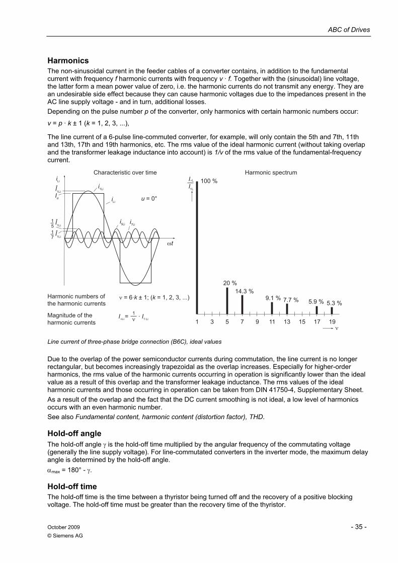
ABC of Drives
October 2009 - 35 - © Siemens AG
Harmonics The non-sinusoidal current in the feeder cables of a converter contains, in addition to the fundamental current with frequency f harmonic currents with frequency v · f. Together with the (sinusoidal) line voltage, the latter form a mean power value of zero, i.e. the harmonic currents do not transmit any energy. They are an undesirable side effect because they can cause harmonic voltages due to the impedances present in the AC line supply voltage - and in turn, additional losses. Depending on the pulse number p of the converter, only harmonics with certain harmonic numbers occur:
v = p · k ± 1 (k = 1, 2, 3, ...),
The line current of a 6-pulse line-commuted converter, for example, will only contain the 5th and 7th, 11th and 13th, 17th and 19th harmonics, etc. The rms value of the ideal harmonic current (without taking overlap and the transformer leakage inductance into account) is 1/v of the rms value of the fundamental-frequency current.
Magnitude of the harmonic currents
Harmonic numbers of the harmonic currents
Harmonic spectrumCharacteristic over time
5.3 %5.9 % 7.7 % 9.1 % 14.3 %
Lii
1 · I= 1 LiI1 3 5 7 9 11 13 15 17 19
20 %
100 % I L1
I
71
1LiÎ51
1LiÎ
1LiÎdI
7Lii5Lii
Lii1Lii
u = 0°
Line current of three-phase bridge connection (B6C), ideal values
Due to the overlap of the power semiconductor currents during commutation, the line current is no longer rectangular, but becomes increasingly trapezoidal as the overlap increases. Especially for higher-order harmonics, the rms value of the harmonic currents occurring in operation is significantly lower than the ideal value as a result of this overlap and the transformer leakage inductance. The rms values of the ideal harmonic currents and those occurring in operation can be taken from DIN 41750-4, Supplementary Sheet. As a result of the overlap and the fact that the DC current smoothing is not ideal, a low level of harmonics occurs with an even harmonic number. See also Fundamental content, harmonic content (distortion factor), THD.
Hold-off angle The hold-off angle γ is the hold-off time multiplied by the angular frequency of the commutating voltage (generally the line supply voltage). For line-commutated converters in the inverter mode, the maximum delay angle is determined by the hold-off angle. αmax = 180° - γ.
Hold-off time The hold-off time is the time between a thyristor being turned off and the recovery of a positive blocking voltage. The hold-off time must be greater than the recovery time of the thyristor.
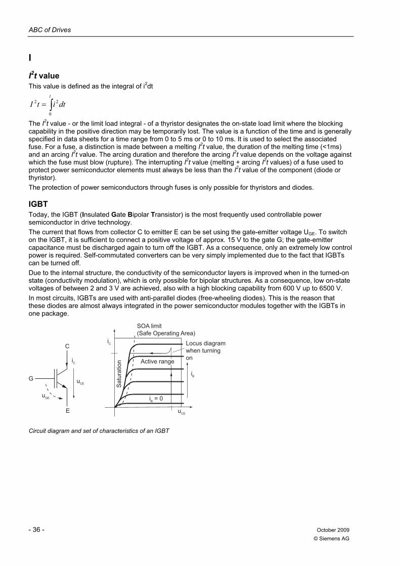
ABC of Drives
- 36 - October 2009 © Siemens AG
I
I2t value This value is defined as the integral of i2dt
dtitIt
∫=0
22
The I2t value - or the limit load integral - of a thyristor designates the on-state load limit where the blocking capability in the positive direction may be temporarily lost. The value is a function of the time and is generally specified in data sheets for a time range from 0 to 5 ms or 0 to 10 ms. It is used to select the associated fuse. For a fuse, a distinction is made between a melting I2t value, the duration of the melting time (<1ms) and an arcing I2t value. The arcing duration and therefore the arcing I2t value depends on the voltage against which the fuse must blow (rupture). The interrupting I2t value (melting + arcing I2t values) of a fuse used to protect power semiconductor elements must always be less than the I2t value of the component (diode or thyristor). The protection of power semiconductors through fuses is only possible for thyristors and diodes.
IGBT Today, the IGBT (Insulated Gate Bipolar Transistor) is the most frequently used controllable power semiconductor in drive technology. The current that flows from collector C to emitter E can be set using the gate-emitter voltage UGE. To switch on the IGBT, it is sufficient to connect a positive voltage of approx. 15 V to the gate G; the gate-emitter capacitance must be discharged again to turn off the IGBT. As a consequence, only an extremely low control power is required. Self-commutated converters can be very simply implemented due to the fact that IGBTs can be turned off. Due to the internal structure, the conductivity of the semiconductor layers is improved when in the turned-on state (conductivity modulation), which is only possible for bipolar structures. As a consequence, low on-state voltages of between 2 and 3 V are achieved, also with a high blocking capability from 600 V up to 6500 V. In most circuits, IGBTs are used with anti-parallel diodes (free-wheeling diodes). This is the reason that these diodes are almost always integrated in the power semiconductor modules together with the IGBTs in one package.
Active range
Locus diagram when turning on
Sat
urat
ion
SOA limit(Safe Operating Area)
EGu
E
B = 0i
Bi
Ci
Ci
ECu
ECuG
C
Circuit diagram and set of characteristics of an IGBT
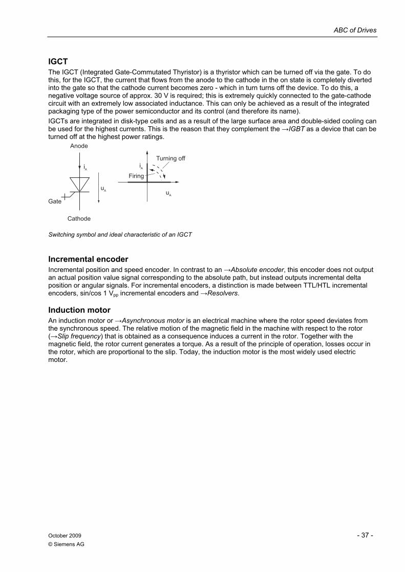
ABC of Drives
October 2009 - 37 - © Siemens AG
IGCT The IGCT (Integrated Gate-Commutated Thyristor) is a thyristor which can be turned off via the gate. To do this, for the IGCT, the current that flows from the anode to the cathode in the on state is completely diverted into the gate so that the cathode current becomes zero - which in turn turns off the device. To do this, a negative voltage source of approx. 30 V is required; this is extremely quickly connected to the gate-cathode circuit with an extremely low associated inductance. This can only be achieved as a result of the integrated packaging type of the power semiconductor and its control (and therefore its name). IGCTs are integrated in disk-type cells and as a result of the large surface area and double-sided cooling can be used for the highest currents. This is the reason that they complement the →IGBT as a device that can be turned off at the highest power ratings.
Gate
Cathode
Firing
Turning off
Anode
AiAi
AuAu
Switching symbol and ideal characteristic of an IGCT
Incremental encoder Incremental position and speed encoder. In contrast to an →Absolute encoder, this encoder does not output an actual position value signal corresponding to the absolute path, but instead outputs incremental delta position or angular signals. For incremental encoders, a distinction is made between TTL/HTL incremental encoders, sin/cos 1 Vpp incremental encoders and →Resolvers.
Induction motor An induction motor or →Asynchronous motor is an electrical machine where the rotor speed deviates from the synchronous speed. The relative motion of the magnetic field in the machine with respect to the rotor (→Slip frequency) that is obtained as a consequence induces a current in the rotor. Together with the magnetic field, the rotor current generates a torque. As a result of the principle of operation, losses occur in the rotor, which are proportional to the slip. Today, the induction motor is the most widely used electric motor.
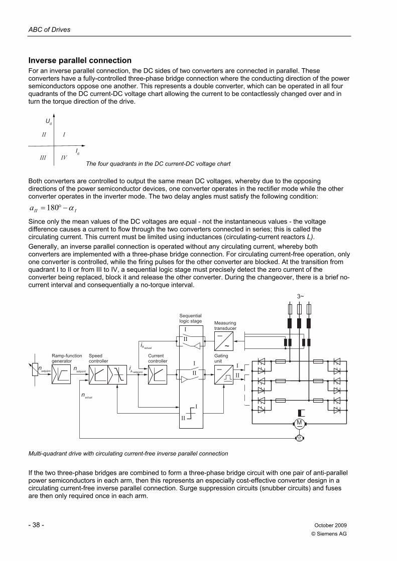
ABC of Drives
- 38 - October 2009 © Siemens AG
Inverse parallel connection For an inverse parallel connection, the DC sides of two converters are connected in parallel. These converters have a fully-controlled three-phase bridge connection where the conducting direction of the power semiconductors oppose one another. This represents a double converter, which can be operated in all four quadrants of the DC current-DC voltage chart allowing the current to be contactlessly changed over and in turn the torque direction of the drive.
Ud
Id
II I
III IVThe four quadrants in the DC current-DC voltage chart
Both converters are controlled to output the same mean DC voltages, whereby due to the opposing directions of the power semiconductor devices, one converter operates in the rectifier mode while the other converter operates in the inverter mode. The two delay angles must satisfy the following condition:
IIIa α−°= 180
Since only the mean values of the DC voltages are equal - not the instantaneous values - the voltage difference causes a current to flow through the two converters connected in series; this is called the circulating current. This current must be limited using inductances (circulating-current reactors L). Generally, an inverse parallel connection is operated without any circulating current, whereby both converters are implemented with a three-phase bridge connection. For circulating current-free operation, only one converter is controlled, while the firing pulses for the other converter are blocked. At the transition from quadrant I to II or from III to IV, a sequential logic stage must precisely detect the zero current of the converter being replaced, block it and release the other converter. During the changeover, there is a brief no-current interval and consequentially a no-torque interval.
Ramp-function generator
Speed controller
Sequential logic stage Measuring
transducer
Gating unit
Current controller
setpoint
actual
setpoint
actual
setpointn
n
nA
i
III
II
I
III
III
3~
G
M
_i
A
_
~
Multi-quadrant drive with circulating current-free inverse parallel connection
If the two three-phase bridges are combined to form a three-phase bridge circuit with one pair of anti-parallel power semiconductors in each arm, then this represents an especially cost-effective converter design in a circulating current-free inverse parallel connection. Surge suppression circuits (snubber circuits) and fuses are then only required once in each arm.
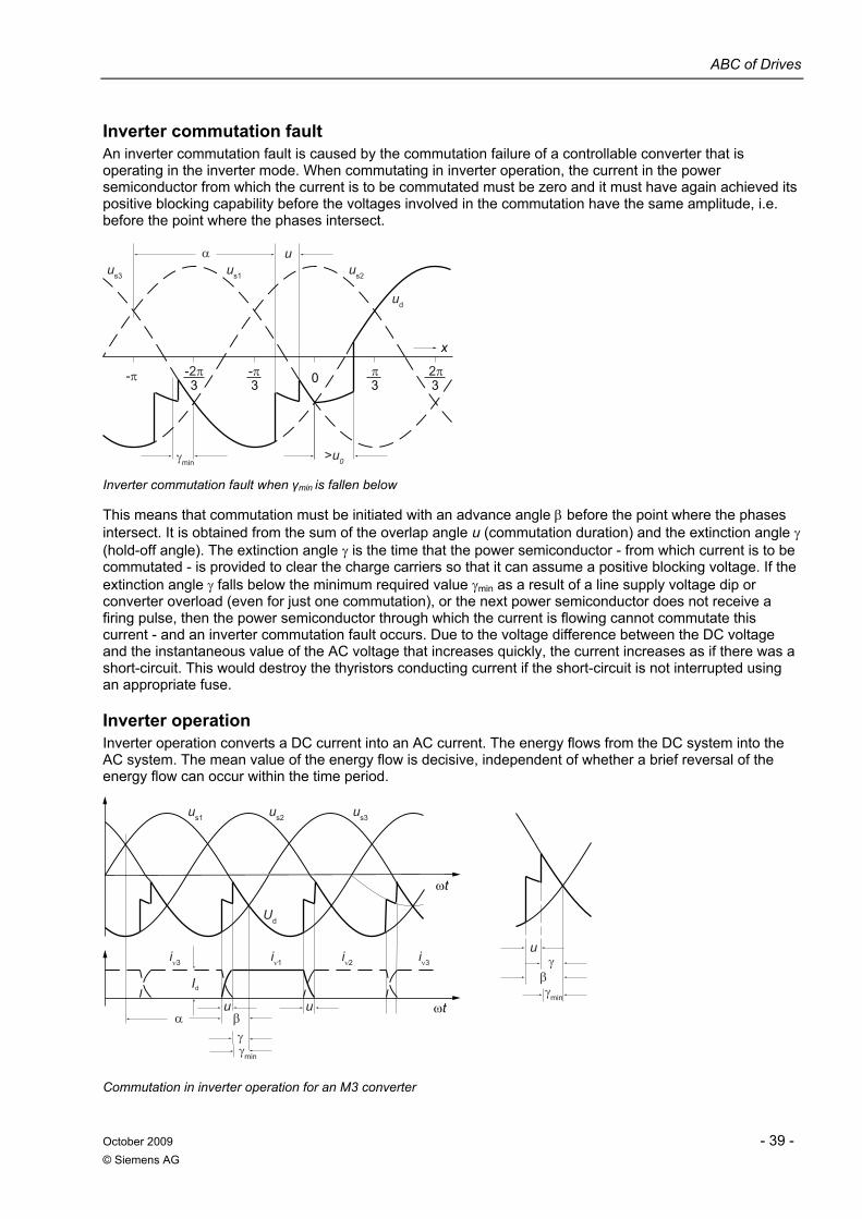
ABC of Drives
October 2009 - 39 - © Siemens AG
Inverter commutation fault An inverter commutation fault is caused by the commutation failure of a controllable converter that is operating in the inverter mode. When commutating in inverter operation, the current in the power semiconductor from which the current is to be commutated must be zero and it must have again achieved its positive blocking capability before the voltages involved in the commutation have the same amplitude, i.e. before the point where the phases intersect.
γmin
-π -2π -π
αus3 us1 us2
>u0
32π33
π30
x
u
ud
Inverter commutation fault when γmin is fallen below
This means that commutation must be initiated with an advance angle β before the point where the phases intersect. It is obtained from the sum of the overlap angle u (commutation duration) and the extinction angle γ (hold-off angle). The extinction angle γ is the time that the power semiconductor - from which current is to be commutated - is provided to clear the charge carriers so that it can assume a positive blocking voltage. If the extinction angle γ falls below the minimum required value γmin as a result of a line supply voltage dip or converter overload (even for just one commutation), or the next power semiconductor does not receive a firing pulse, then the power semiconductor through which the current is flowing cannot commutate this current - and an inverter commutation fault occurs. Due to the voltage difference between the DC voltage and the instantaneous value of the AC voltage that increases quickly, the current increases as if there was a short-circuit. This would destroy the thyristors conducting current if the short-circuit is not interrupted using an appropriate fuse.
Inverter operation Inverter operation converts a DC current into an AC current. The energy flows from the DC system into the AC system. The mean value of the energy flow is decisive, independent of whether a brief reversal of the energy flow can occur within the time period.
Ud
us1 us2 us3
ωt
ωt
u
iν3 iν1 iν2 iν3
Id
u
uγ
γ
γmin
γmin
β
βα
Commutation in inverter operation for an M3 converter
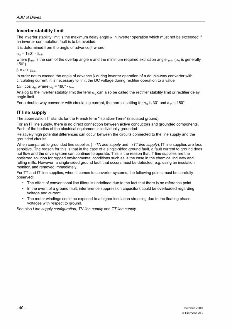
ABC of Drives
- 40 - October 2009 © Siemens AG
Inverter stability limit The inverter stability limit is the maximum delay angle α in inverter operation which must not be exceeded if an inverter commutation fault is to be avoided. It is determined from the angle of advance β where αw = 180° - βmin where βmin is the sum of the overlap angle u and the minimum required extinction angle γmin (αw is generally 150°). β = u + γmin In order not to exceed the angle of advance β during inverter operation of a double-way converter with circulating current, it is necessary to limit the DC voltage during rectifier operation to a value Udi · cos αg, where αg = 180° - αw Analog to the inverter stability limit the term αg can also be called the rectifier stability limit or rectifier delay angle limit. For a double-way converter with circulating current, the normal setting for αg is 30° and αw is 150°.
IT line supply The abbreviation IT stands for the French term "Isolation-Terre" (insulated ground). For an IT line supply, there is no direct connection between active conductors and grounded components. Each of the bodies of the electrical equipment is individually grounded. Relatively high potential differences can occur between the circuits connected to the line supply and the grounded circuits. When compared to grounded line supplies (→TN line supply and →TT line supply), IT line supplies are less sensitive. The reason for this is that in the case of a single-sided ground fault, a fault current to ground does not flow and the drive system can continue to operate. This is the reason that IT line supplies are the preferred solution for rugged environmental conditions such as is the case in the chemical industry and rolling mills. However, a single-sided ground fault that occurs must be detected, e.g. using an insulation monitor, and removed immediately. For TT and IT line supplies, when it comes to converter systems, the following points must be carefully observed:
• The effect of conventional line filters is undefined due to the fact that there is no reference point. • In the event of a ground fault, interference suppression capacitors could be overloaded regarding
voltage and current. • The motor windings could be exposed to a higher insulation stressing due to the floating phase
voltages with respect to ground. See also Line supply configuration, TN line supply and TT line supply.

ABC of Drives
October 2009 - 41 - © Siemens AG
K
Kinetic buffering Kinetic buffering (KIP) is a software function that can be used to buffer transient line failures (up to approx. 1 s or as long as the drive continues to turn). Kinetic buffering can usually only be used on drives that are primarily used in the motoring mode. In this case, the precondition is that the driven machine has a sufficiently high rotating mass, i.e. has sufficient kinetic energy. When the line supply fails, the KIP function causes the motor to either operate under no-load or go slightly into the regenerative mode (in order to cover the low losses of the motor and inverter). The drive immediately goes into the motoring mode once the line supply returns. In order to use kinetic buffering, the technological conditions must allow the motor to coast down or brake for the duration of the line supply failure.
ABC of Drives
- 42 - October 2009 © Siemens AG
L
Line filters Line filters are filters at the converter input that are designed to protect the line supply from harmonic loads and/or interference voltages generated in the converter. Line filters can be passive or active filters, for the lower-frequency harmonics (called line harmonics) with 5, 7, 11, 13, etc. times the line frequency, and for high-frequency interference voltages from 10 kHz and above (RFI suppression filters). In conjunction with SINAMICS, line filters are exclusively passive RFI suppression filters.
Line harmonics Line harmonics involve a connected piece of equipment, which influences the line supply voltage. The line supply is influenced as active and reactive power are drawn - especially when these quantities change quickly or periodically - and harmonics are generated, especially low-order harmonics. The line harmonics generated by a converter predominantly comprise current harmonics (due to the non-sinusoidal line current), which generate the corresponding voltages across the line impedances. These are then manifested as voltage harmonics on the line supply voltage. See also Commutating dip, Harmonics.
Line Module A Line Module is a power unit belonging to the SINAMICS S120 product family. It generates the DC link voltage for one or several Motor Modules from a three-phase line supply. The following three types of Line Module are used in the SINAMICS system: →Basic Line Module, →Smart Line Module and →Active Line Module.
Line reactor A line reactor is a reactor that is either connected in an AC feeder cable to the converter unit (phase reactor) or is located in an arm of the converter circuit (arm reactor). Line reactors are used to limit low-frequency line harmonics to permissible values. In conjunction with Active Line Modules (SINAMICS product family) they are additionally used as energy storage device.
Line supply configuration A distinction is made between the following line supply configurations regarding the implementation of the neutral point (star point) and the grounding for low-voltage line supplies: →TN line supply →TT line supply →IT line supply
Line-commutated converters Line-commutated converters fall in the category of externally-commutated converters, whereby the commutation voltage is taken from the AC supply system as setpoint. See also Externally-commutated converter.
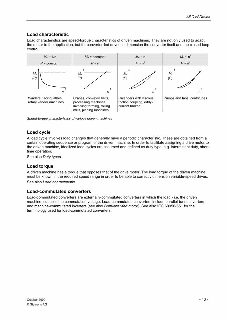
ABC of Drives
October 2009 - 43 - © Siemens AG
Load characteristic Load characteristics are speed-torque characteristics of driven machines. They are not only used to adapt the motor to the application, but for converter-fed drives to dimension the converter itself and the closed-loop control.
Md ~ 1/n Md = constant Md ~ n Md ~ n2
P = constant P ~ n P ~ n2 P ~ n3
n
(P)Md
n
(P)Md
n
(P)Md
n
(P)Md
Winders, facing lathes, rotary veneer machines
Cranes, conveyor belts, processing machines involving forming, rolling mills, planing machines
Calenders with viscous friction coupling, eddy-current brakes
Pumps and fans, centrifuges
Speed-torque characteristics of various driven machines
Load cycle A load cycle involves load changes that generally have a periodic characteristic. These are obtained from a certain operating sequence or program of the driven machine. In order to facilitate assigning a drive motor to the driven machine, idealized load cycles are assumed and defined as duty type, e.g. intermittent duty, short-time operation. See also Duty types.
Load torque A driven machine has a torque that opposes that of the drive motor. The load torque of the driven machine must be known in the required speed range in order to be able to correctly dimension variable-speed drives. See also Load characteristic.
Load-commutated converters Load-commutated converters are externally-commutated converters in which the load - i.e. the driven machine, supplies the commutation voltage. Load-commutated converters include parallel-tuned inverters and machine-commutated inverters (see also Converter-fed motor). See also IEC 60050-551 for the terminology used for load-commutated converters.
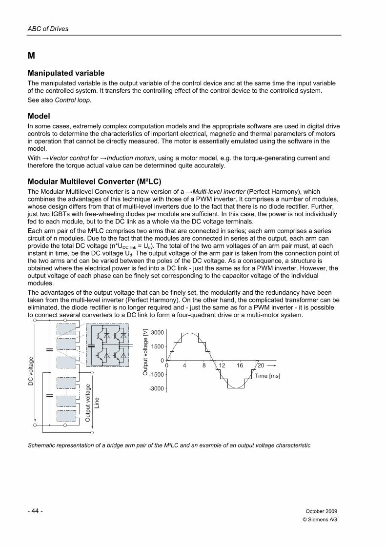
ABC of Drives
- 44 - October 2009 © Siemens AG
M
Manipulated variable The manipulated variable is the output variable of the control device and at the same time the input variable of the controlled system. It transfers the controlling effect of the control device to the controlled system. See also Control loop.
Model In some cases, extremely complex computation models and the appropriate software are used in digital drive controls to determine the characteristics of important electrical, magnetic and thermal parameters of motors in operation that cannot be directly measured. The motor is essentially emulated using the software in the model. With →Vector control for →Induction motors, using a motor model, e.g. the torque-generating current and therefore the torque actual value can be determined quite accurately.
Modular Multilevel Converter (M²LC) The Modular Multilevel Converter is a new version of a →Multi-level inverter (Perfect Harmony), which combines the advantages of this technique with those of a PWM inverter. It comprises a number of modules, whose design differs from that of multi-level inverters due to the fact that there is no diode rectifier. Further, just two IGBTs with free-wheeling diodes per module are sufficient. In this case, the power is not individually fed to each module, but to the DC link as a whole via the DC voltage terminals. Each arm pair of the M²LC comprises two arms that are connected in series; each arm comprises a series circuit of n modules. Due to the fact that the modules are connected in series at the output, each arm can provide the total DC voltage (n*UDC link = Ud). The total of the two arm voltages of an arm pair must, at each instant in time, be the DC voltage Ud. The output voltage of the arm pair is taken from the connection point of the two arms and can be varied between the poles of the DC voltage. As a consequence, a structure is obtained where the electrical power is fed into a DC link - just the same as for a PWM inverter. However, the output voltage of each phase can be finely set corresponding to the capacitor voltage of the individual modules. The advantages of the output voltage that can be finely set, the modularity and the redundancy have been taken from the multi-level inverter (Perfect Harmony). On the other hand, the complicated transformer can be eliminated, the diode rectifier is no longer required and - just the same as for a PWM inverter - it is possible to connect several converters to a DC link to form a four-quadrant drive or a multi-motor system.
3000
1500
0
-1500
-3000
0 4 8 12 16 20
Line
DC
vol
tage
Out
put v
olta
ge
Out
put v
olta
ge [V
]
Time [ms]
Schematic representation of a bridge arm pair of the M²LC and an example of an output voltage characteristic
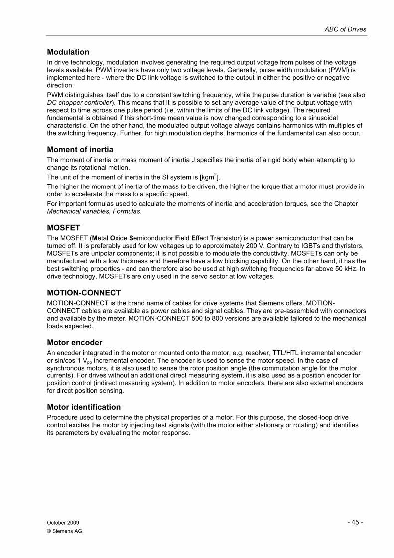
ABC of Drives
October 2009 - 45 - © Siemens AG
Modulation In drive technology, modulation involves generating the required output voltage from pulses of the voltage levels available. PWM inverters have only two voltage levels. Generally, pulse width modulation (PWM) is implemented here - where the DC link voltage is switched to the output in either the positive or negative direction. PWM distinguishes itself due to a constant switching frequency, while the pulse duration is variable (see also DC chopper controller). This means that it is possible to set any average value of the output voltage with respect to time across one pulse period (i.e. within the limits of the DC link voltage). The required fundamental is obtained if this short-time mean value is now changed corresponding to a sinusoidal characteristic. On the other hand, the modulated output voltage always contains harmonics with multiples of the switching frequency. Further, for high modulation depths, harmonics of the fundamental can also occur.
Moment of inertia The moment of inertia or mass moment of inertia J specifies the inertia of a rigid body when attempting to change its rotational motion. The unit of the moment of inertia in the SI system is [kgm2]. The higher the moment of inertia of the mass to be driven, the higher the torque that a motor must provide in order to accelerate the mass to a specific speed. For important formulas used to calculate the moments of inertia and acceleration torques, see the Chapter Mechanical variables, Formulas.
MOSFET The MOSFET (Metal Oxide Semiconductor Field Effect Transistor) is a power semiconductor that can be turned off. It is preferably used for low voltages up to approximately 200 V. Contrary to IGBTs and thyristors, MOSFETs are unipolar components; it is not possible to modulate the conductivity. MOSFETs can only be manufactured with a low thickness and therefore have a low blocking capability. On the other hand, it has the best switching properties - and can therefore also be used at high switching frequencies far above 50 kHz. In drive technology, MOSFETs are only used in the servo sector at low voltages.
MOTION-CONNECT MOTION-CONNECT is the brand name of cables for drive systems that Siemens offers. MOTION-CONNECT cables are available as power cables and signal cables. They are pre-assembled with connectors and available by the meter. MOTION-CONNECT 500 to 800 versions are available tailored to the mechanical loads expected.
Motor encoder An encoder integrated in the motor or mounted onto the motor, e.g. resolver, TTL/HTL incremental encoder or sin/cos 1 Vpp incremental encoder. The encoder is used to sense the motor speed. In the case of synchronous motors, it is also used to sense the rotor position angle (the commutation angle for the motor currents). For drives without an additional direct measuring system, it is also used as a position encoder for position control (indirect measuring system). In addition to motor encoders, there are also external encoders for direct position sensing.
Motor identification Procedure used to determine the physical properties of a motor. For this purpose, the closed-loop drive control excites the motor by injecting test signals (with the motor either stationary or rotating) and identifies its parameters by evaluating the motor response.
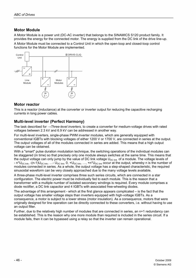
ABC of Drives
- 46 - October 2009 © Siemens AG
Motor Module A Motor Module is a power unit (DC-AC inverter) that belongs to the SINAMICS S120 product family. It provides the energy for the connected motor. The energy is supplied from the DC link of the drive line-up. A Motor Module must be connected to a Control Unit in which the open-loop and closed-loop control functions for the Motor Module are implemented.
~
=
MotorModules
LineModule
ControlUnit
=
~
M3 ~
=
~
M3 ~
DRIVE-CLiQ
Motor reactor This is a reactor (inductance) at the converter or inverter output for reducing the capacitive recharging currents in long power cables.
Multi-level inverter (Perfect Harmony) The task described for →Three-level inverters, to create a converter for medium-voltage drives with rated voltages between 2.3 kV and 6.9 kV can be addressed in another way. For multi-level inverters, single-phase PWM inverter modules, which are generally equipped with conventional IGBTs with blocking voltages of either 1200 V or 1700 V, are connected in series at the output. The output voltages of all of the modules connected in series are added. This means that a high output voltage can be obtained. With a "smart" pulse duration modulation technique, the switching operations of the individual modules can be staggered (in time) so that precisely only one module always switches at the same time. This means that the output voltage can only jump by the value of DC link voltage UDC link of a module. The voltage levels of - n*UDC link, -(n-1)UDC link, …- UDC link, 0, +UDC link, …, +n*UDC link occur at the output, whereby n is the number of modules connected in series. As a whole, the output voltage has a step-shaped characteristic, the required sinusoidal waveform can be very closely approached due to the many voltage levels available. A three-phase multi-level inverter comprises three such series circuits, which are connected in a star configuration. The electric power must be individually fed to each module. This is the reason that a transformer with a multiple number of isolated secondary windings is required. Every module comprises a diode rectifier, a DC link capacitor and 4 IGBTs with associated free-wheeling diodes. The advantage of this arrangement - which at the first glance appears complicated – is the fact that the output voltage has smaller voltage steps than inverters equipped with high-voltage IGBTs. As a consequence, a motor is subject to a lower stress (motor insulation). As a consequence, motors that were originally designed for line operation can be directly connected to these converters, i.e. without having to use an output filter. Further, due to the relatively high number of modules that are connected in series, an n+1 redundancy can be established. This is the reason why one more module than required is included in the series circuit. If a module fails, then it can be bypassed using a relay so that the inverter can remain operational.
ABC of Drives
October 2009 - 47 - © Siemens AG
MI
Circuit diagram of Perfect Harmony and the output voltage waveform for a 7-level multi-level inverter with n = 3 modules in series per phase
Multi-quadrant drive A multi-quadrant drive can be operated in several quadrants of the speed-torque chart, e.g. driving and braking with a clockwise direction of rotation (two-quadrant drive) or driving and braking in the clockwise and counter-clockwise directions of rotation (four-quadrant drive). See also Single-quadrant drive.

ABC of Drives
- 48 - October 2009 © Siemens AG
N
Nominal value According to DIN EN 60947-1, a suitable, rounded-off value of a quantity used to designate or identify a component, a device or a piece of equipment. According to IEC 60050-151, the value of a quantity which is used to designate and identify a component, a device, a piece of equipment or a system. Note: Rated value is normally used in German. Generally, a nominal value is a value that is rounded off. See also Rated value.
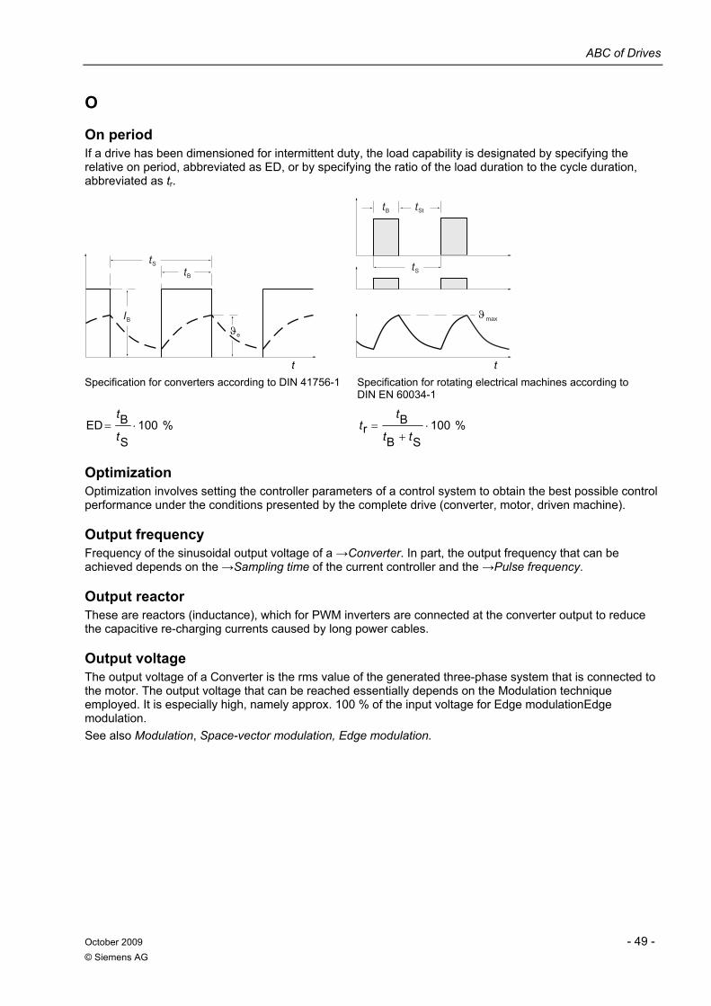
ABC of Drives
October 2009 - 49 - © Siemens AG
O
On period If a drive has been dimensioned for intermittent duty, the load capability is designated by specifying the relative on period, abbreviated as ED, or by specifying the ratio of the load duration to the cycle duration, abbreviated as tr.
t
ϑϑIB
tB
e
tS
t
tS
max
tB tSt
Specification for converters according to DIN 41756-1 Specification for rotating electrical machines according to
DIN EN 60034-1
%100S
BED ⋅=t
t %100
SB
Br ⋅
+=
tt
tt
Optimization Optimization involves setting the controller parameters of a control system to obtain the best possible control performance under the conditions presented by the complete drive (converter, motor, driven machine).
Output frequency Frequency of the sinusoidal output voltage of a →Converter. In part, the output frequency that can be achieved depends on the →Sampling time of the current controller and the →Pulse frequency.
Output reactor These are reactors (inductance), which for PWM inverters are connected at the converter output to reduce the capacitive re-charging currents caused by long power cables.
Output voltage The output voltage of a Converter is the rms value of the generated three-phase system that is connected to the motor. The output voltage that can be reached essentially depends on the Modulation technique employed. It is especially high, namely approx. 100 % of the input voltage for Edge modulationEdge modulation. See also Modulation, Space-vector modulation, Edge modulation.
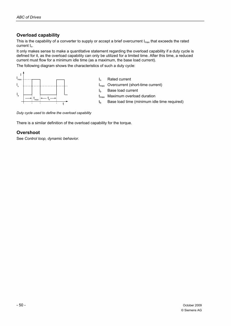
ABC of Drives
- 50 - October 2009 © Siemens AG
Overload capability This is the capability of a converter to supply or accept a brief overcurrent Imax that exceeds the rated current In. It only makes sense to make a quantitative statement regarding the overload capability if a duty cycle is defined for it, as the overload capability can only be utilized for a limited time. After this time, a reduced current must flow for a minimum idle time (as a maximum, the base load current). The following diagram shows the characteristics of such a duty cycle:
Imax
tmax
t
In
Ibtb
I
In Rated current Imax Overcurrent (short-time current) Ib Base load current tmax Maximum overload duration tb Base load time (minimum idle time required)
Duty cycle used to define the overload capability
There is a similar definition of the overload capability for the torque.
Overshoot See Control loop, dynamic behavior.
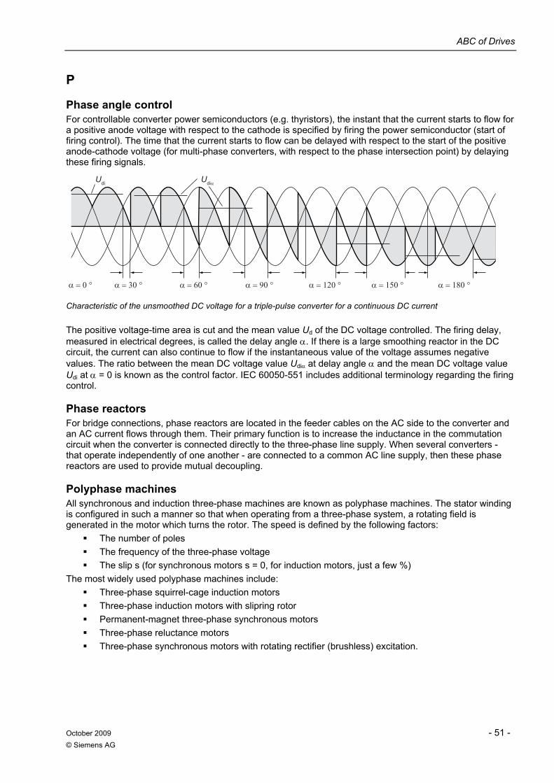
ABC of Drives
October 2009 - 51 - © Siemens AG
P
Phase angle control For controllable converter power semiconductors (e.g. thyristors), the instant that the current starts to flow for a positive anode voltage with respect to the cathode is specified by firing the power semiconductor (start of firing control). The time that the current starts to flow can be delayed with respect to the start of the positive anode-cathode voltage (for multi-phase converters, with respect to the phase intersection point) by delaying these firing signals.
UdiαUdi
α = 30 °α = 0 ° α = 60 ° α = 90 ° α = 120 ° α = 150 ° α = 180 °
Characteristic of the unsmoothed DC voltage for a triple-pulse converter for a continuous DC current
The positive voltage-time area is cut and the mean value Ud of the DC voltage controlled. The firing delay, measured in electrical degrees, is called the delay angle α. If there is a large smoothing reactor in the DC circuit, the current can also continue to flow if the instantaneous value of the voltage assumes negative values. The ratio between the mean DC voltage value Udiα at delay angle α and the mean DC voltage value Udi at α = 0 is known as the control factor. IEC 60050-551 includes additional terminology regarding the firing control.
Phase reactors For bridge connections, phase reactors are located in the feeder cables on the AC side to the converter and an AC current flows through them. Their primary function is to increase the inductance in the commutation circuit when the converter is connected directly to the three-phase line supply. When several converters - that operate independently of one another - are connected to a common AC line supply, then these phase reactors are used to provide mutual decoupling.
Polyphase machines All synchronous and induction three-phase machines are known as polyphase machines. The stator winding is configured in such a manner so that when operating from a three-phase system, a rotating field is generated in the motor which turns the rotor. The speed is defined by the following factors:
The number of poles The frequency of the three-phase voltage The slip s (for synchronous motors s = 0, for induction motors, just a few %)
The most widely used polyphase machines include: Three-phase squirrel-cage induction motors Three-phase induction motors with slipring rotor Permanent-magnet three-phase synchronous motors Three-phase reluctance motors Three-phase synchronous motors with rotating rectifier (brushless) excitation.
ABC of Drives
- 52 - October 2009 © Siemens AG
Position controller Generally, a position controller is a P controller (less frequently a PI controller), which cyclically compares the internal digital position setpoint to the digital actual value of the measuring system. The result of this setpoint/actual value comparison is a signed differential value. The proportional gain of the position controller is known as the position loop gain or Kv factor. The output signal of the position controller acts on the speed controller in order to correct a position error.
Power factor The power factor λ is always the ratio between the active power P and the apparent power S.
SP=λ
If a converter is operated on a "soft" line supply, i.e. if its ideal DC power Udi · IdN is significantly higher than 1 % of the line short-circuit power (system fault level), then when determining the active power P, in addition to the non-sinusoidal current characteristic, also the non-sinusoidal voltage characteristic must be taken into account. The power factor λ is then obtained as follows
IU
dttituT
SP
⋅
⋅=
∫=
)()(1
λ
For an ideal DC power up to approximately 1 % of the line short-circuit power (system fault level), it is safe to assume that the voltage at the line terminals of the converter will be adequately sinusoidal. For non-sinusoidal current and sinusoidal voltage, the power factor λ is calculated from the fundamental content gI of the current and the displacement factor (fundamental-frequency power factor) cos 1ϕ
1cos1
1cos ϕϕλ ⋅=⋅=
I
IIg
I1 is the fundamental-frequency component of the current I, φ1 is the phase shift between the voltage and current fundamentals. For a non-sinusoidal line current (i.e. a line current containing harmonics), power factor λ is always less that the displacement factor cosφ1. The power factor is only equal to the displacement factor if the line voltage and line current are sinusoidal (however, for converters this is never the case).
ϕλ cos=
Power Module For the SINAMICS drive system, a Power Module is a complete AC-AC converter, which does not have an integrated →Control Unit.
Pre-charging Charging the DC link capacitors through resistors. Pre-charging is normally performed from the line supply, but can also be performed from a pre-charged DC link (DC coupling).
Pre-charging circuit For converters with DC link, large capacitances are required in the →DC link. Power semiconductors (→Diodes or →IGBTs) are used in the line-side converter (e.g. →Line Module). When connected to the line supply, these power semiconductors permit current to flow in the DC link therefore quickly charging up the DC link capacitor. If no other measures are taken, when connecting directly to the line supply, the charging current would be so high that the power semiconductors or the other components would be damaged. This is the reason that the DC link capacitors are charged through a pre-charging circuit, e.g. via pre-charging resistors - initially with a lower current - up to approximately the line supply voltage. The pre-charging circuit is then bypassed, e.g. using a bypass contactor, and the line-side converter is directly connected to the line supply.
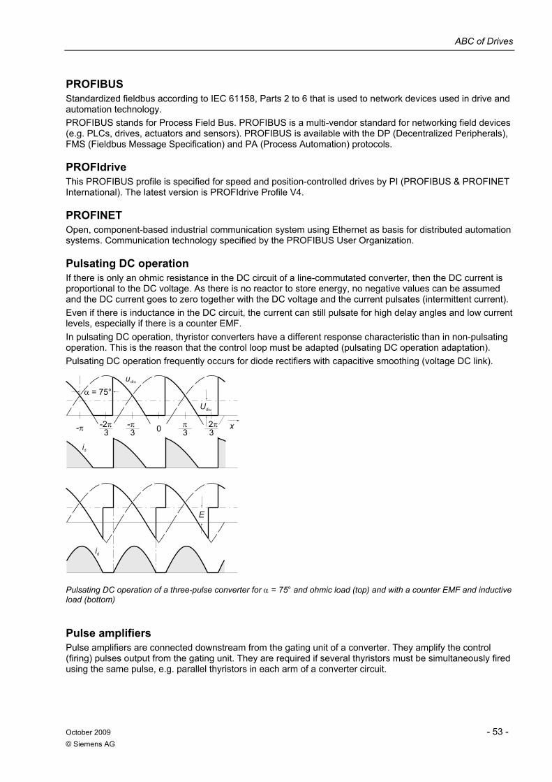
ABC of Drives
October 2009 - 53 - © Siemens AG
PROFIBUS Standardized fieldbus according to IEC 61158, Parts 2 to 6 that is used to network devices used in drive and automation technology. PROFIBUS stands for Process Field Bus. PROFIBUS is a multi-vendor standard for networking field devices (e.g. PLCs, drives, actuators and sensors). PROFIBUS is available with the DP (Decentralized Peripherals), FMS (Fieldbus Message Specification) and PA (Process Automation) protocols.
PROFIdrive This PROFIBUS profile is specified for speed and position-controlled drives by PI (PROFIBUS & PROFINET International). The latest version is PROFIdrive Profile V4.
PROFINET Open, component-based industrial communication system using Ethernet as basis for distributed automation systems. Communication technology specified by the PROFIBUS User Organization.
Pulsating DC operation If there is only an ohmic resistance in the DC circuit of a line-commutated converter, then the DC current is proportional to the DC voltage. As there is no reactor to store energy, no negative values can be assumed and the DC current goes to zero together with the DC voltage and the current pulsates (intermittent current). Even if there is inductance in the DC circuit, the current can still pulsate for high delay angles and low current levels, especially if there is a counter EMF. In pulsating DC operation, thyristor converters have a different response characteristic than in non-pulsating operation. This is the reason that the control loop must be adapted (pulsating DC operation adaptation). Pulsating DC operation frequently occurs for diode rectifiers with capacitive smoothing (voltage DC link).
-2π π3
2π3
udiα
Udiα
-π3
α = 75°
-π 30 x
id
id
E
Pulsating DC operation of a three-pulse converter for α = 75° and ohmic load (top) and with a counter EMF and inductive load (bottom)
Pulse amplifiers Pulse amplifiers are connected downstream from the gating unit of a converter. They amplify the control (firing) pulses output from the gating unit. They are required if several thyristors must be simultaneously fired using the same pulse, e.g. parallel thyristors in each arm of a converter circuit.
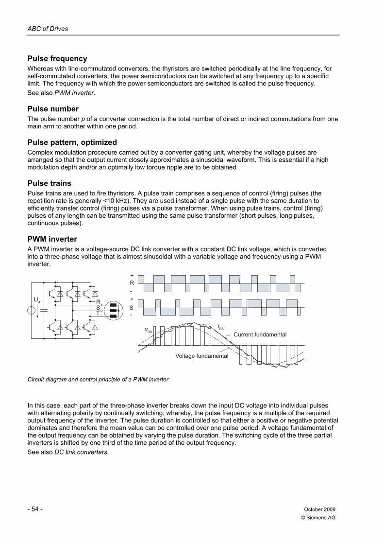
ABC of Drives
- 54 - October 2009 © Siemens AG
Pulse frequency Whereas with line-commutated converters, the thyristors are switched periodically at the line frequency, for self-commutated converters, the power semiconductors can be switched at any frequency up to a specific limit. The frequency with which the power semiconductors are switched is called the pulse frequency. See also PWM inverter.
Pulse number The pulse number p of a converter connection is the total number of direct or indirect commutations from one main arm to another within one period.
Pulse pattern, optimized Complex modulation procedure carried out by a converter gating unit, whereby the voltage pulses are arranged so that the output current closely approximates a sinusoidal waveform. This is essential if a high modulation depth and/or an optimally low torque ripple are to be obtained.
Pulse trains Pulse trains are used to fire thyristors. A pulse train comprises a sequence of control (firing) pulses (the repetition rate is generally <10 kHz). They are used instead of a single pulse with the same duration to efficiently transfer control (firing) pulses via a pulse transformer. When using pulse trains, control (firing) pulses of any length can be transmitted using the same pulse transformer (short pulses, long pulses, continuous pulses).
PWM inverter A PWM inverter is a voltage-source DC link converter with a constant DC link voltage, which is converted into a three-phase voltage that is almost sinusoidal with a variable voltage and frequency using a PWM inverter.
Current fundamental
Voltage fundamental
Ud RST -
+-
S
+R
iRSuRS
Circuit diagram and control principle of a PWM inverter
In this case, each part of the three-phase inverter breaks down the input DC voltage into individual pulses with alternating polarity by continually switching; whereby, the pulse frequency is a multiple of the required output frequency of the inverter. The pulse duration is controlled so that either a positive or negative potential dominates and therefore the mean value can be controlled over one pulse period. A voltage fundamental of the output frequency can be obtained by varying the pulse duration. The switching cycle of the three partial inverters is shifted by one third of the time period of the output frequency. See also DC link converters.
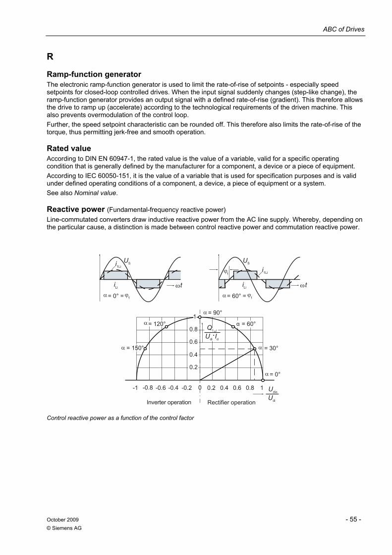
ABC of Drives
October 2009 - 55 - © Siemens AG
R
Ramp-function generator The electronic ramp-function generator is used to limit the rate-of-rise of setpoints - especially speed setpoints for closed-loop controlled drives. When the input signal suddenly changes (step-like change), the ramp-function generator provides an output signal with a defined rate-of-rise (gradient). This therefore allows the drive to ramp up (accelerate) according to the technological requirements of the driven machine. This also prevents overmodulation of the control loop. Further, the speed setpoint characteristic can be rounded off. This therefore also limits the rate-of-rise of the torque, thus permitting jerk-free and smooth operation.
Rated value According to DIN EN 60947-1, the rated value is the value of a variable, valid for a specific operating condition that is generally defined by the manufacturer for a component, a device or a piece of equipment. According to IEC 60050-151, it is the value of a variable that is used for specification purposes and is valid under defined operating conditions of a component, a device, a piece of equipment or a system. See also Nominal value.
Reactive power (Fundamental-frequency reactive power) Line-commutated converters draw inductive reactive power from the AC line supply. Whereby, depending on the particular cause, a distinction is made between control reactive power and commutation reactive power.
Rectifier operationInverter operation
0.2
0.8
0.6
0.4
-0.2-0.4-0.6-0.8 0.6 0.8 10.2 0.4
diUαdiU
d·diU Ii1Q
0
1
-1
1
= 150°
= 0°
= 30°
= 60°α
= 90°
= 120°
1 = 0° = 1 = 60° = Lii
1LiiSU
tLii
1Lii SU
t
Control reactive power as a function of the control factor
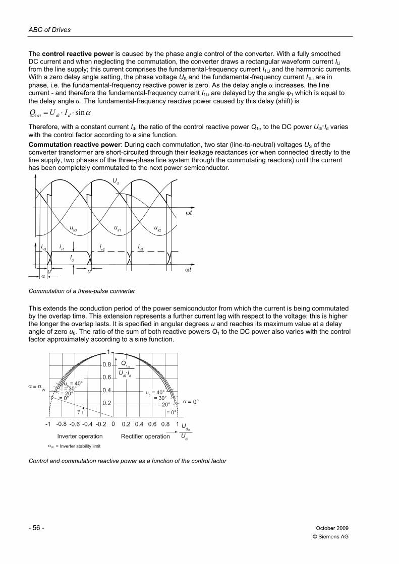
ABC of Drives
- 56 - October 2009 © Siemens AG
The control reactive power is caused by the phase angle control of the converter. With a fully smoothed DC current and when neglecting the commutation, the converter draws a rectangular waveform current ILi from the line supply; this current comprises the fundamental-frequency current I1Li and the harmonic currents. With a zero delay angle setting, the phase voltage US and the fundamental-frequency current I1Li are in phase, i.e. the fundamental-frequency reactive power is zero. As the delay angle α increases, the line current - and therefore the fundamental-frequency current I1Li are delayed by the angle φ1 which is equal to the delay angle α. The fundamental-frequency reactive power caused by this delay (shift) is
αα sin1 ⋅⋅= ddii IUQ Therefore, with a constant current Id, the ratio of the control reactive power Q1α to the DC power Udi·Id varies with the control factor according to a sine function. Commutation reactive power: During each commutation, two star (line-to-neutral) voltages US of the converter transformer are short-circuited through their leakage reactances (or when connected directly to the line supply, two phases of the three-phase line system through the commutating reactors) until the current has been completely commutated to the next power semiconductor.
ωt
Ud
Id
us3 us1 us2
ωtuuα
iν3 iν3iν2iν1
Commutation of a three-pulse converter
This extends the conduction period of the power semiconductor from which the current is being commutated by the overlap time. This extension represents a further current lag with respect to the voltage; this is higher the longer the overlap lasts. It is specified in angular degrees u and reaches its maximum value at a delay angle of zero u0. The ratio of the sum of both reactive powers Q1 to the DC power also varies with the control factor approximately according to a sine function.
Rectifier operationInverter operation= Inverter stability limit
-0.2-0.4-0.6-0.8 0.2 0.4 0.6 0.8 1
0.2
0.8
0.6
0.4= 20°= 0°
1
= 0°
= 40°0
u
= 40°0
u
W
W =
= 0°= 20°
= 30°
= 30°
1Q
dU
dI·
diU
diU
0-1
Control and commutation reactive power as a function of the control factor
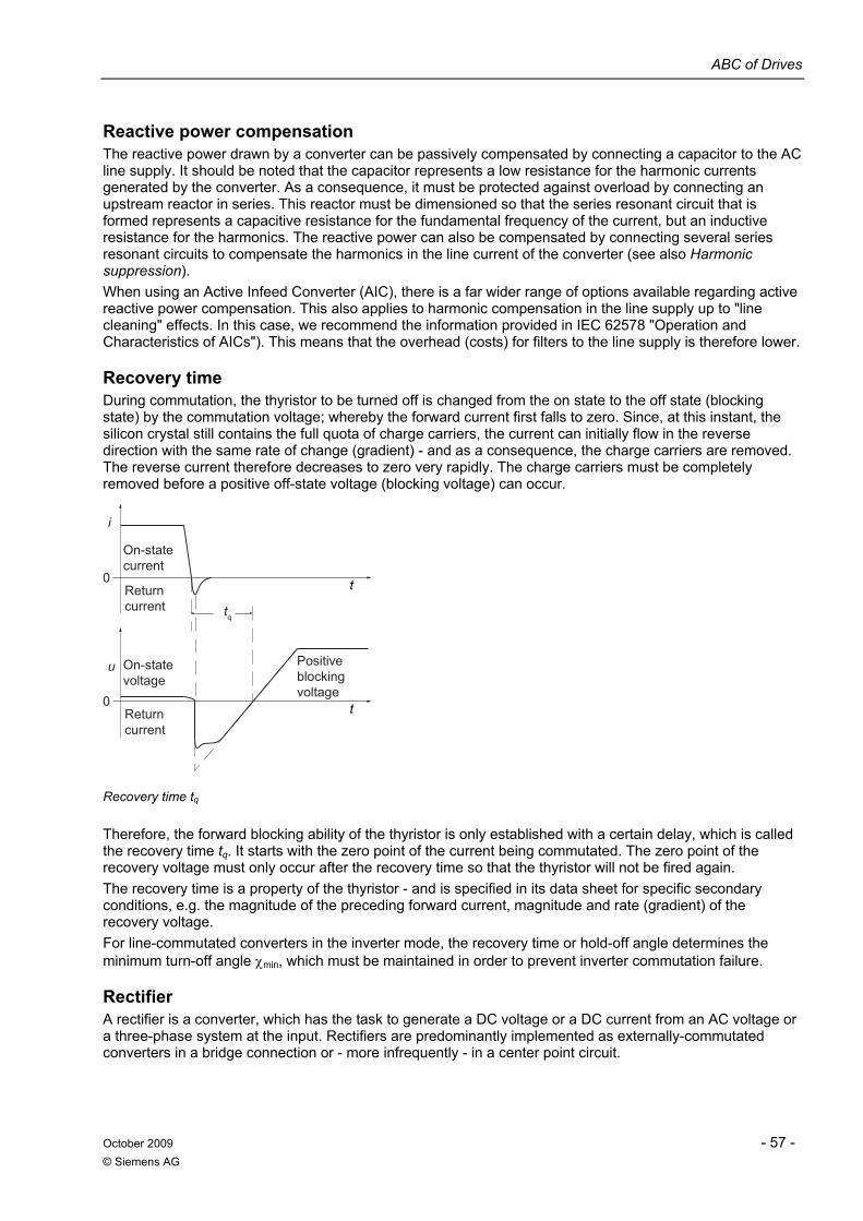
ABC of Drives
October 2009 - 57 - © Siemens AG
Reactive power compensation The reactive power drawn by a converter can be passively compensated by connecting a capacitor to the AC line supply. It should be noted that the capacitor represents a low resistance for the harmonic currents generated by the converter. As a consequence, it must be protected against overload by connecting an upstream reactor in series. This reactor must be dimensioned so that the series resonant circuit that is formed represents a capacitive resistance for the fundamental frequency of the current, but an inductive resistance for the harmonics. The reactive power can also be compensated by connecting several series resonant circuits to compensate the harmonics in the line current of the converter (see also Harmonic suppression). When using an Active Infeed Converter (AIC), there is a far wider range of options available regarding active reactive power compensation. This also applies to harmonic compensation in the line supply up to "line cleaning" effects. In this case, we recommend the information provided in IEC 62578 "Operation and Characteristics of AICs"). This means that the overhead (costs) for filters to the line supply is therefore lower.
Recovery time During commutation, the thyristor to be turned off is changed from the on state to the off state (blocking state) by the commutation voltage; whereby the forward current first falls to zero. Since, at this instant, the silicon crystal still contains the full quota of charge carriers, the current can initially flow in the reverse direction with the same rate of change (gradient) - and as a consequence, the charge carriers are removed. The reverse current therefore decreases to zero very rapidly. The charge carriers must be completely removed before a positive off-state voltage (blocking voltage) can occur.
Positive blocking voltage
Return current
On-state voltage
Return current
On-state current
u
0 t
i
0
tq
t
Recovery time tq
Therefore, the forward blocking ability of the thyristor is only established with a certain delay, which is called the recovery time tq. It starts with the zero point of the current being commutated. The zero point of the recovery voltage must only occur after the recovery time so that the thyristor will not be fired again. The recovery time is a property of the thyristor - and is specified in its data sheet for specific secondary conditions, e.g. the magnitude of the preceding forward current, magnitude and rate (gradient) of the recovery voltage. For line-commutated converters in the inverter mode, the recovery time or hold-off angle determines the minimum turn-off angle χmin, which must be maintained in order to prevent inverter commutation failure.
Rectifier A rectifier is a converter, which has the task to generate a DC voltage or a DC current from an AC voltage or a three-phase system at the input. Rectifiers are predominantly implemented as externally-commutated converters in a bridge connection or - more infrequently - in a center point circuit.
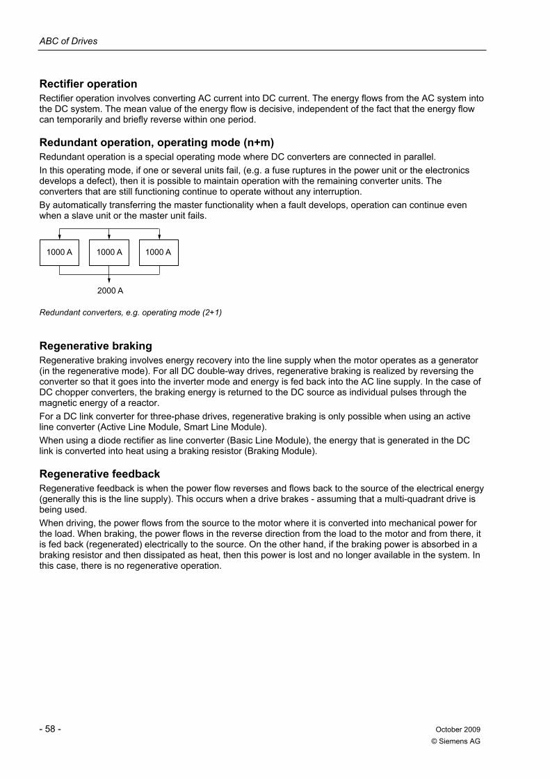
ABC of Drives
- 58 - October 2009 © Siemens AG
Rectifier operation Rectifier operation involves converting AC current into DC current. The energy flows from the AC system into the DC system. The mean value of the energy flow is decisive, independent of the fact that the energy flow can temporarily and briefly reverse within one period.
Redundant operation, operating mode (n+m) Redundant operation is a special operating mode where DC converters are connected in parallel. In this operating mode, if one or several units fail, (e.g. a fuse ruptures in the power unit or the electronics develops a defect), then it is possible to maintain operation with the remaining converter units. The converters that are still functioning continue to operate without any interruption. By automatically transferring the master functionality when a fault develops, operation can continue even when a slave unit or the master unit fails.
1000 A 1000 A 1000 A
2000 A
Redundant converters, e.g. operating mode (2+1)
Regenerative braking Regenerative braking involves energy recovery into the line supply when the motor operates as a generator (in the regenerative mode). For all DC double-way drives, regenerative braking is realized by reversing the converter so that it goes into the inverter mode and energy is fed back into the AC line supply. In the case of DC chopper converters, the braking energy is returned to the DC source as individual pulses through the magnetic energy of a reactor. For a DC link converter for three-phase drives, regenerative braking is only possible when using an active line converter (Active Line Module, Smart Line Module). When using a diode rectifier as line converter (Basic Line Module), the energy that is generated in the DC link is converted into heat using a braking resistor (Braking Module).
Regenerative feedback Regenerative feedback is when the power flow reverses and flows back to the source of the electrical energy (generally this is the line supply). This occurs when a drive brakes - assuming that a multi-quadrant drive is being used. When driving, the power flows from the source to the motor where it is converted into mechanical power for the load. When braking, the power flows in the reverse direction from the load to the motor and from there, it is fed back (regenerated) electrically to the source. On the other hand, if the braking power is absorbed in a braking resistor and then dissipated as heat, then this power is lost and no longer available in the system. In this case, there is no regenerative operation.
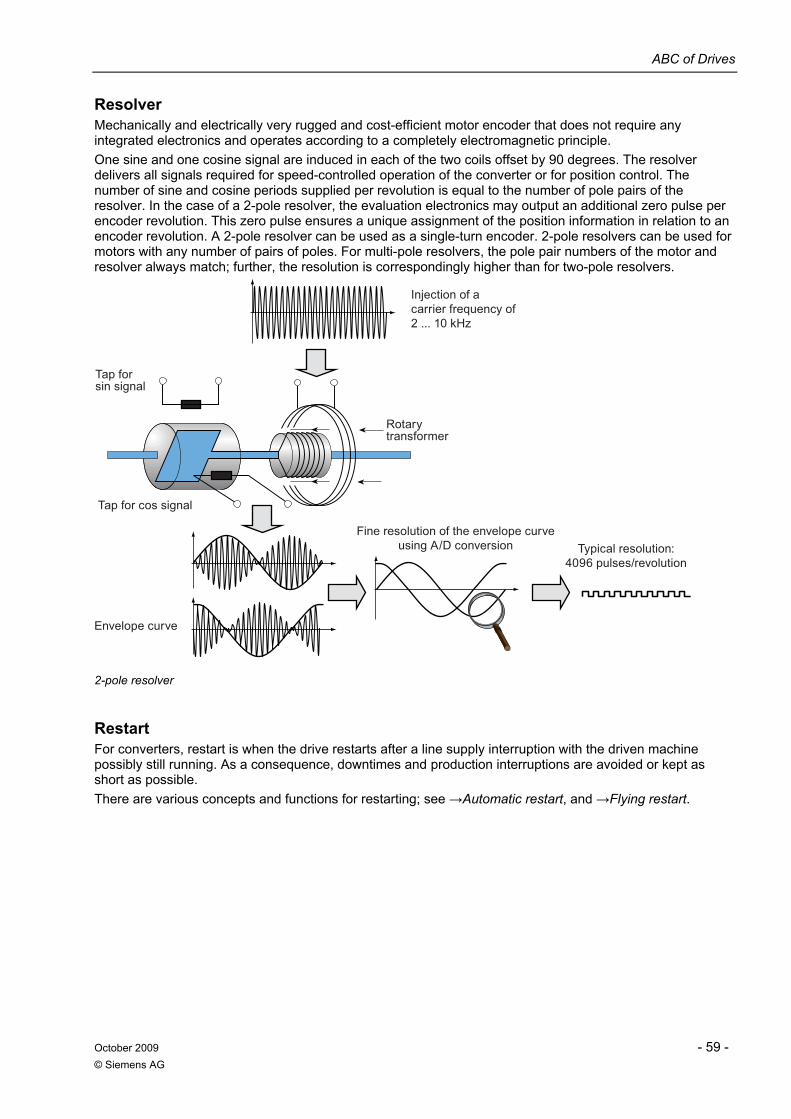
ABC of Drives
October 2009 - 59 - © Siemens AG
Resolver Mechanically and electrically very rugged and cost-efficient motor encoder that does not require any integrated electronics and operates according to a completely electromagnetic principle. One sine and one cosine signal are induced in each of the two coils offset by 90 degrees. The resolver delivers all signals required for speed-controlled operation of the converter or for position control. The number of sine and cosine periods supplied per revolution is equal to the number of pole pairs of the resolver. In the case of a 2-pole resolver, the evaluation electronics may output an additional zero pulse per encoder revolution. This zero pulse ensures a unique assignment of the position information in relation to an encoder revolution. A 2-pole resolver can be used as a single-turn encoder. 2-pole resolvers can be used for motors with any number of pairs of poles. For multi-pole resolvers, the pole pair numbers of the motor and resolver always match; further, the resolution is correspondingly higher than for two-pole resolvers.
Injection of acarrier frequency of2 ... 10 kHz
Fine resolution of the envelope curveusing A/D conversion Typical resolution:
4096 pulses/revolution
Envelope curve
Rotarytransformer
Tap forsin signal
Tap for cos signal
2-pole resolver
Restart For converters, restart is when the drive restarts after a line supply interruption with the driven machine possibly still running. As a consequence, downtimes and production interruptions are avoided or kept as short as possible. There are various concepts and functions for restarting; see →Automatic restart, and →Flying restart.
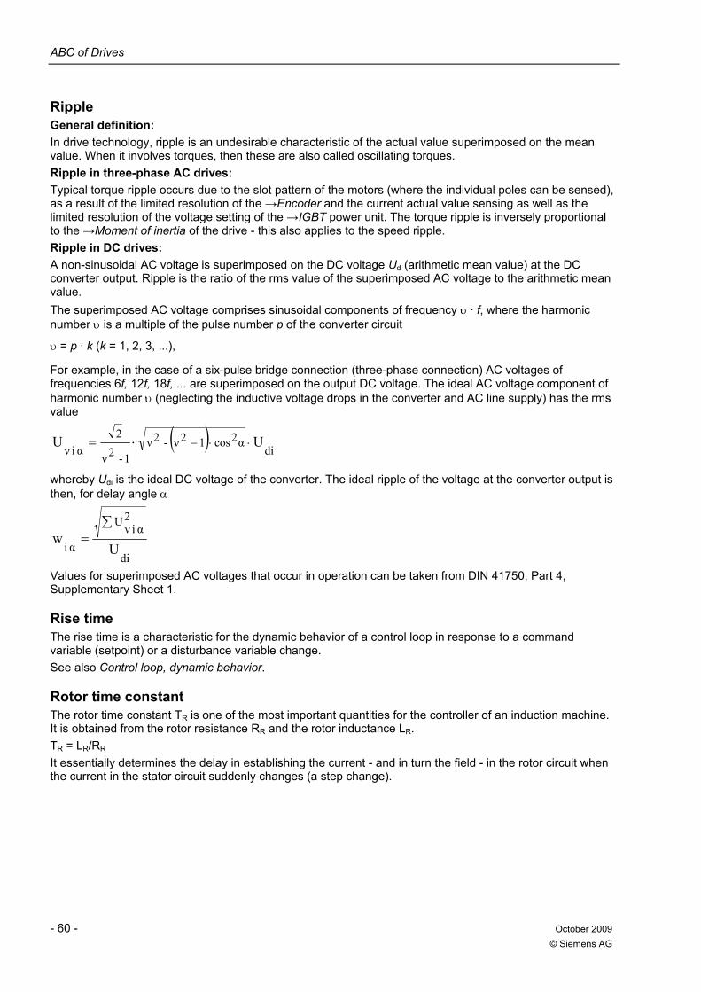
ABC of Drives
- 60 - October 2009 © Siemens AG
Ripple General definition: In drive technology, ripple is an undesirable characteristic of the actual value superimposed on the mean value. When it involves torques, then these are also called oscillating torques. Ripple in three-phase AC drives: Typical torque ripple occurs due to the slot pattern of the motors (where the individual poles can be sensed), as a result of the limited resolution of the →Encoder and the current actual value sensing as well as the limited resolution of the voltage setting of the →IGBT power unit. The torque ripple is inversely proportional to the →Moment of inertia of the drive - this also applies to the speed ripple. Ripple in DC drives: A non-sinusoidal AC voltage is superimposed on the DC voltage Ud (arithmetic mean value) at the DC converter output. Ripple is the ratio of the rms value of the superimposed AC voltage to the arithmetic mean value. The superimposed AC voltage comprises sinusoidal components of frequency υ · f, where the harmonic number υ is a multiple of the pulse number p of the converter circuit
υ = p · k (k = 1, 2, 3, ...),
For example, in the case of a six-pulse bridge connection (three-phase connection) AC voltages of frequencies 6f, 12f, 18f, ... are superimposed on the output DC voltage. The ideal AC voltage component of harmonic number υ (neglecting the inductive voltage drops in the converter and AC line supply) has the rms value
( )di
α2cos12ν-2ν1-2ν
2αiν
UU ⋅⋅−⋅=
whereby Udi is the ideal DC voltage of the converter. The ideal ripple of the voltage at the converter output is then, for delay angle α
di
2αiνU
αi Uw
∑=
Values for superimposed AC voltages that occur in operation can be taken from DIN 41750, Part 4, Supplementary Sheet 1.
Rise time The rise time is a characteristic for the dynamic behavior of a control loop in response to a command variable (setpoint) or a disturbance variable change. See also Control loop, dynamic behavior.
Rotor time constant The rotor time constant TR is one of the most important quantities for the controller of an induction machine. It is obtained from the rotor resistance RR and the rotor inductance LR. TR = LR/RR It essentially determines the delay in establishing the current - and in turn the field - in the rotor circuit when the current in the stator circuit suddenly changes (a step change).
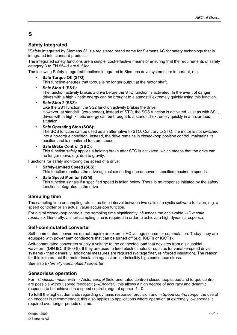
ABC of Drives
October 2009 - 61 - © Siemens AG
S
Safety Integrated "Safety Integrated by Siemens ®" is a registered brand name for Siemens AG for safety technology that is integrated into standard products. The integrated safety functions are a simple, cost-effective means of ensuring that the requirements of safety category 3 to EN 954-1 are fulfilled. The following Safety Integrated functions integrated in Siemens drive systems are important, e.g.
• Safe Torque Off (STO): This function ensures that torque is no longer output at the motor shaft.
• Safe Stop 1 (SS1): The function actively brakes a drive before the STO function is activated. In the event of danger, drives with a high kinetic energy can be brought to a standstill extremely quickly using this function.
• Safe Stop 2 (SS2): Like the SS1 function, the SS2 function actively brakes the drive. However, at standstill (zero speed), instead of STO, the SOS function is activated. Just as with SS1, drives with a high kinetic energy can be brought to a standstill extremely quickly in a hazardous situation.
• Safe Operating Stop (SOS): The SOS function can be used as an alternative to STO. Contrary to STO, the motor is not switched into a no-torque condition. Instead, the drive remains in closed-loop position control, maintains its position and is monitored for zero speed.
• Safe Brake Control (SBC): This function safely applies a holding brake after STO is activated, which means that the drive can no longer move, e.g. due to gravity.
Functions for safely monitoring the speed of a drive: • Safely-Limited Speed (SLS):
This function monitors the drive against exceeding one or several specified maximum speeds. • Safe Speed Monitor (SSM):
This function signals if a specified speed is fallen below. There is no response initiated by the safety functions integrated in the drive.
Sampling time The sampling time or sampling rate is the time interval between two calls of a cyclic software function, e.g. a speed controller or an actual value acquisition function. For digital closed-loop controls, the sampling time significantly influences the achievable →Dynamic response: Generally, a short sampling time is required in order to achieve a high dynamic response.
Self-commutated converter Self-commutated converters do not require an external AC voltage source for commutation. Today, they are equipped with power semiconductors that can be turned off (e.g. IGBTs or IGCTs). Self-commutated converters supply a voltage to the connected load that deviates from a sinusoidal waveform (DIN IEC 61800-8). If they are used to feed electric motors - such as for variable-speed drive systems - then generally, additional measures are required (voltage filter, reinforced insulation). The reason for this is to protect the motor insulation against an inadmissibly high continuous stress. See also Externally-commutated converter.
Sensorless operation For →Induction motor with →Vector control (field-orientated control) closed-loop speed and torque control are possible without speed feedback (→Encoder); this allows a high degree of accuracy and dynamic response to be achieved in a speed control range of approx. 1:10. To fulfill the highest demands regarding dynamic response, precision and →Speed control range, the use of an encoder is recommended; this also applies to applications where operation at extremely low speeds is required over longer periods of time.
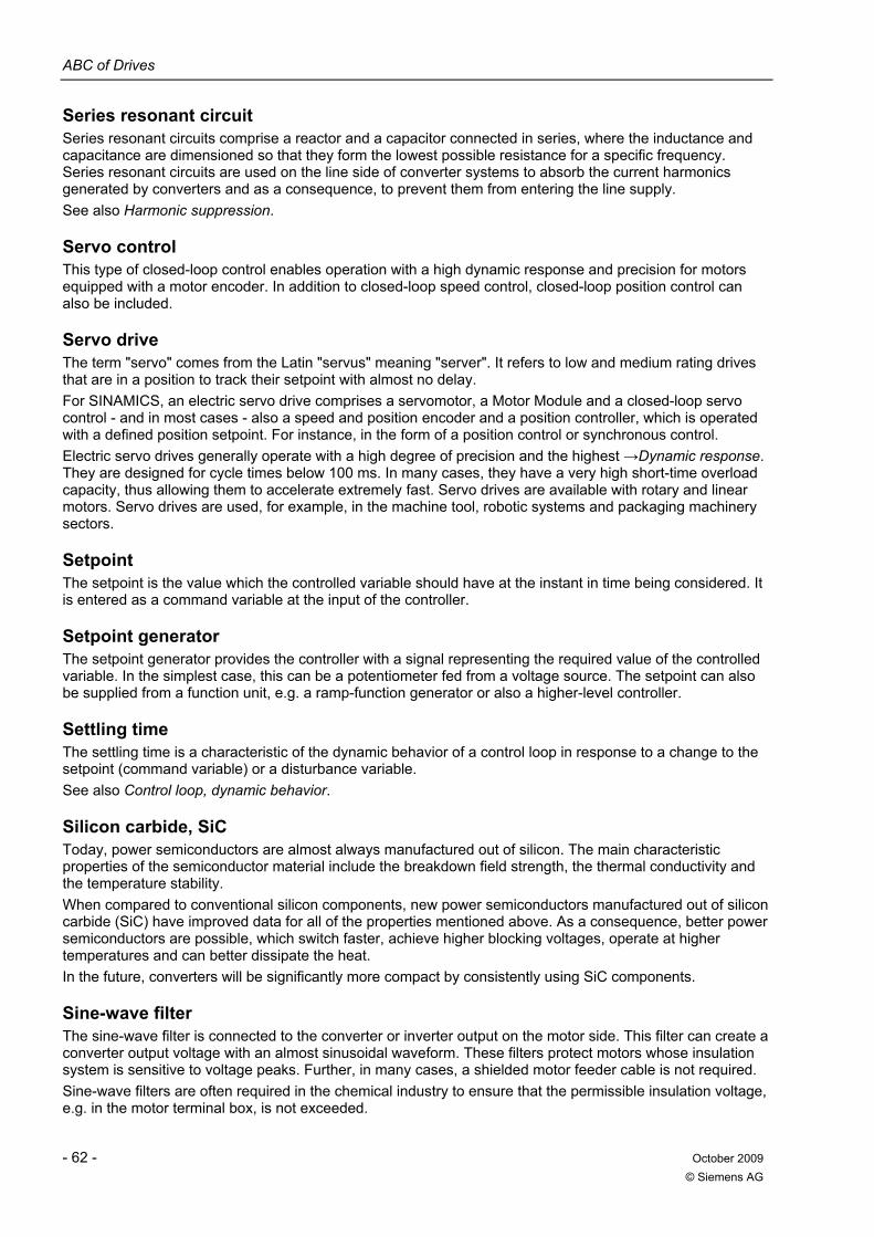
ABC of Drives
- 62 - October 2009 © Siemens AG
Series resonant circuit Series resonant circuits comprise a reactor and a capacitor connected in series, where the inductance and capacitance are dimensioned so that they form the lowest possible resistance for a specific frequency. Series resonant circuits are used on the line side of converter systems to absorb the current harmonics generated by converters and as a consequence, to prevent them from entering the line supply. See also Harmonic suppression.
Servo control This type of closed-loop control enables operation with a high dynamic response and precision for motors equipped with a motor encoder. In addition to closed-loop speed control, closed-loop position control can also be included.
Servo drive The term "servo" comes from the Latin "servus" meaning "server". It refers to low and medium rating drives that are in a position to track their setpoint with almost no delay. For SINAMICS, an electric servo drive comprises a servomotor, a Motor Module and a closed-loop servo control - and in most cases - also a speed and position encoder and a position controller, which is operated with a defined position setpoint. For instance, in the form of a position control or synchronous control. Electric servo drives generally operate with a high degree of precision and the highest →Dynamic response. They are designed for cycle times below 100 ms. In many cases, they have a very high short-time overload capacity, thus allowing them to accelerate extremely fast. Servo drives are available with rotary and linear motors. Servo drives are used, for example, in the machine tool, robotic systems and packaging machinery sectors.
Setpoint The setpoint is the value which the controlled variable should have at the instant in time being considered. It is entered as a command variable at the input of the controller.
Setpoint generator The setpoint generator provides the controller with a signal representing the required value of the controlled variable. In the simplest case, this can be a potentiometer fed from a voltage source. The setpoint can also be supplied from a function unit, e.g. a ramp-function generator or also a higher-level controller.
Settling time The settling time is a characteristic of the dynamic behavior of a control loop in response to a change to the setpoint (command variable) or a disturbance variable. See also Control loop, dynamic behavior.
Silicon carbide, SiC Today, power semiconductors are almost always manufactured out of silicon. The main characteristic properties of the semiconductor material include the breakdown field strength, the thermal conductivity and the temperature stability. When compared to conventional silicon components, new power semiconductors manufactured out of silicon carbide (SiC) have improved data for all of the properties mentioned above. As a consequence, better power semiconductors are possible, which switch faster, achieve higher blocking voltages, operate at higher temperatures and can better dissipate the heat. In the future, converters will be significantly more compact by consistently using SiC components.
Sine-wave filter The sine-wave filter is connected to the converter or inverter output on the motor side. This filter can create a converter output voltage with an almost sinusoidal waveform. These filters protect motors whose insulation system is sensitive to voltage peaks. Further, in many cases, a shielded motor feeder cable is not required. Sine-wave filters are often required in the chemical industry to ensure that the permissible insulation voltage, e.g. in the motor terminal box, is not exceeded.
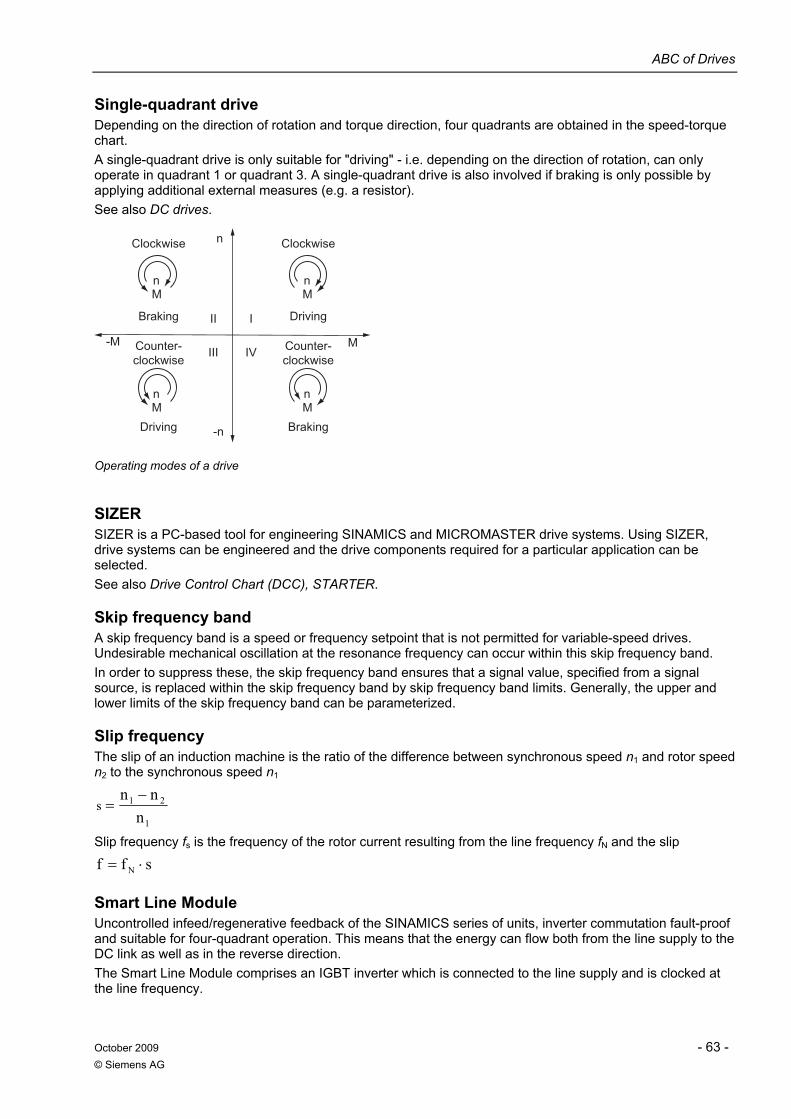
ABC of Drives
October 2009 - 63 - © Siemens AG
Single-quadrant drive Depending on the direction of rotation and torque direction, four quadrants are obtained in the speed-torque chart. A single-quadrant drive is only suitable for "driving" - i.e. depending on the direction of rotation, can only operate in quadrant 1 or quadrant 3. A single-quadrant drive is also involved if braking is only possible by applying additional external measures (e.g. a resistor). See also DC drives.
Counter-clockwise
Driving Braking
Braking
Clockwise
Counter-clockwise
Driving
Clockwise
IVIII
III
-M
-n
Mn
Mn
Mn
M
n
Mn
Operating modes of a drive
SIZER SIZER is a PC-based tool for engineering SINAMICS and MICROMASTER drive systems. Using SIZER, drive systems can be engineered and the drive components required for a particular application can be selected. See also Drive Control Chart (DCC), STARTER.
Skip frequency band A skip frequency band is a speed or frequency setpoint that is not permitted for variable-speed drives. Undesirable mechanical oscillation at the resonance frequency can occur within this skip frequency band. In order to suppress these, the skip frequency band ensures that a signal value, specified from a signal source, is replaced within the skip frequency band by skip frequency band limits. Generally, the upper and lower limits of the skip frequency band can be parameterized.
Slip frequency The slip of an induction machine is the ratio of the difference between synchronous speed n1 and rotor speed n2 to the synchronous speed n1
1
21
nnn
s−
=
Slip frequency fs is the frequency of the rotor current resulting from the line frequency fN and the slip
sff N ⋅=
Smart Line Module Uncontrolled infeed/regenerative feedback of the SINAMICS series of units, inverter commutation fault-proof and suitable for four-quadrant operation. This means that the energy can flow both from the line supply to the DC link as well as in the reverse direction. The Smart Line Module comprises an IGBT inverter which is connected to the line supply and is clocked at the line frequency.
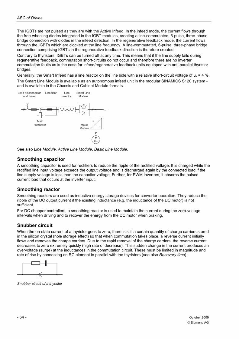
ABC of Drives
- 64 - October 2009 © Siemens AG
The IGBTs are not pulsed as they are with the Active Infeed. In the infeed mode, the current flows through the free-wheeling diodes integrated in the IGBT modules, creating a line-commutated, 6-pulse, three-phase bridge connection with diodes in the infeed direction. In the regenerative feedback mode, the current flows through the IGBTs which are clocked at the line frequency. A line-commutated, 6-pulse, three-phase bridge connection comprising IGBTs in the regenerative feedback direction is therefore created. Contrary to thyristors, IGBTs can be turned off at any time. This means that if the line supply fails during regenerative feedback, commutation short-circuits do not occur and therefore there are no inverter commutation faults as is the case for infeed/regenerative feedback units equipped with anti-parallel thyristor bridges. Generally, the Smart Infeed has a line reactor on the line side with a relative short-circuit voltage of uk = 4 %. The Smart Line Module is available as an autonomous infeed unit in the modular SINAMICS S120 system - and is available in the Chassis and Cabinet Module formats.
Main contactor
Line filter Line reactor
Load disconnector and fuses
=
3 M
. . .
Motor Module
Smart Line Module
See also Line Module, Active Line Module, Basic Line Module.
Smoothing capacitor A smoothing capacitor is used for rectifiers to reduce the ripple of the rectified voltage. It is charged while the rectified line input voltage exceeds the output voltage and is discharged again by the connected load if the line supply voltage is less than the capacitor voltage. Further, for PWM inverters, it absorbs the pulsed current load that occurs at the inverter input.
Smoothing reactor Smoothing reactors are used as inductive energy storage devices for converter operation. They reduce the ripple of the DC output current if the existing inductance (e.g. the inductance of the DC motor) is not sufficient. For DC chopper controllers, a smoothing reactor is used to maintain the current during the zero-voltage intervals when driving and to recover the energy from the DC motor when braking.
Snubber circuit When the on-state current of a thyristor goes to zero, there is still a certain quantity of charge carriers stored in the silicon crystal (hole storage effect) so that when commutation takes place, a reverse current initially flows and removes the charge carriers. Due to the rapid removal of the charge carriers, the reverse current decreases to zero extremely quickly (high rate of decrease). This sudden change in the current produces an overvoltage (surge) at the inductances in the commutation circuit. These must be limited in magnitude and rate of rise by connecting an RC element in parallel with the thyristors (see also Recovery time).
Snubber circuit of a thyristor
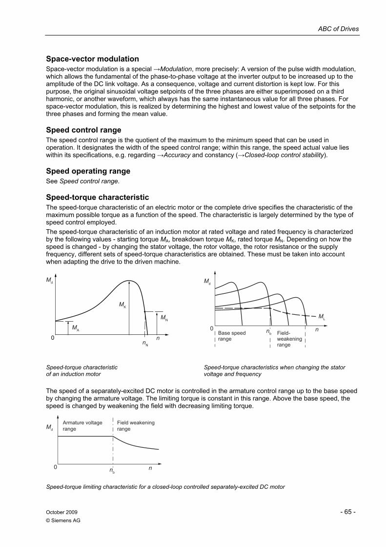
ABC of Drives
October 2009 - 65 - © Siemens AG
Space-vector modulation Space-vector modulation is a special →Modulation, more precisely: A version of the pulse width modulation, which allows the fundamental of the phase-to-phase voltage at the inverter output to be increased up to the amplitude of the DC link voltage. As a consequence, voltage and current distortion is kept low. For this purpose, the original sinusoidal voltage setpoints of the three phases are either superimposed on a third harmonic, or another waveform, which always has the same instantaneous value for all three phases. For space-vector modulation, this is realized by determining the highest and lowest value of the setpoints for the three phases and forming the mean value.
Speed control range The speed control range is the quotient of the maximum to the minimum speed that can be used in operation. It designates the width of the speed control range; within this range, the speed actual value lies within its specifications, e.g. regarding →Accuracy and constancy (→Closed-loop control stability).
Speed operating range See Speed control range.
Speed-torque characteristic The speed-torque characteristic of an electric motor or the complete drive specifies the characteristic of the maximum possible torque as a function of the speed. The characteristic is largely determined by the type of speed control employed. The speed-torque characteristic of an induction motor at rated voltage and rated frequency is characterized by the following values - starting torque MA, breakdown torque MK, rated torque MN. Depending on how the speed is changed - by changing the stator voltage, the rotor voltage, the rotor resistance or the supply frequency, different sets of speed-torque characteristics are obtained. These must be taken into account when adapting the drive to the driven machine.
Md
MA
MK
MN
nN
0 n
Base speed range
Field-weakening range
nbn0
ML
Md
Speed-torque characteristic of an induction motor
Speed-torque characteristics when changing the stator voltage and frequency
The speed of a separately-excited DC motor is controlled in the armature control range up to the base speed by changing the armature voltage. The limiting torque is constant in this range. Above the base speed, the speed is changed by weakening the field with decreasing limiting torque.
Armature voltage range
Field weakening range
nbn
Md
0
Speed-torque limiting characteristic for a closed-loop controlled separately-excited DC motor
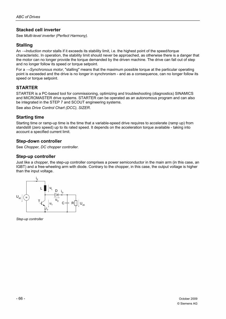
ABC of Drives
- 66 - October 2009 © Siemens AG
Stacked cell inverter See Multi-level inverter (Perfect Harmony).
Stalling An →Induction motor stalls if it exceeds its stability limit, i.e. the highest point of the speed/torque characteristic. In operation, the stability limit should never be approached, as otherwise there is a danger that the motor can no longer provide the torque demanded by the driven machine. The drive can fall out of step and no longer follow its speed or torque setpoint. For a →Synchronous motor, "stalling" means that the maximum possible torque at the particular operating point is exceeded and the drive is no longer in synchronism - and as a consequence, can no longer follow its speed or torque setpoint.
STARTER STARTER is a PC-based tool for commissioning, optimizing and troubleshooting (diagnostics) SINAMICS and MICROMASTER drive systems. STARTER can be operated as an autonomous program and can also be integrated in the STEP 7 and SCOUT engineering systems. See also Drive Control Chart (DCC), SIZER.
Starting time Starting time or ramp-up time is the time that a variable-speed drive requires to accelerate (ramp up) from standstill (zero speed) up to its rated speed. It depends on the acceleration torque available - taking into account a specified current limit.
Step-down controller See Chopper, DC chopper controller.
Step-up controller Just like a chopper, the step-up controller comprises a power semiconductor in the main arm (in this case, an IGBT) and a free-wheeling arm with diode. Contrary to the chopper, in this case, the output voltage is higher than the input voltage.
iE
iD
iT
UdA
uDuT
=
DL
T C R
uL
UdE
Step-up controller
ABC of Drives
October 2009 - 67 - © Siemens AG
Synchronous motor For a synchronous motor, the stator magnetic field (rotating field) - which rotates with the synchronous speed - and the magnetic field of the rotor (rotating DC field) generate a torque. For a synchronous motor, the rotor always rotates in synchronism with the stator magnetic field (the rotating field). Together with the magnetic field of the rotor (rotating DC field), a torque is generated. The synchronous speed ns (in rpm) is obtained from the supply frequency f (in Hz) of the motor divided by the pole pair number p. ns = 60*f/p The magnetic field in the rotor is either generated electromagnetically, where the current is transferred to the rotor via sliprings, using an exciter or permanent magnets. Contrary to induction motors, synchronous motors have no slip. In order to be fed from a converter, depending on their particular version, synchronous motors require different open-loop and closed-loop controlled concepts. A differentiation is made between synchronous motors
permanently excited/separately excited with/without damping cage with/without position encoder
Synchronous motors are used for various reasons: High drive dynamic response (synchronous servomotors) High overload capability High speed accuracy with precisely the specified frequency (SIEMOSYN motors)
Synchronous servomotor Synchronous servomotors are →Synchronous motors with small up to medium power ratings that have an extremely high →Dynamic response and are extremely compact. These motors are mainly used for fast motion control applications and other applications that demand a high dynamic response and precision. Siemens synchronous servomotors (e.g. 1FK7, 1FT7) are permanently excited (permanent magnet) Synchronous motors with speed/position encoders such as →Incremental encoders or →Absolute encoders. The low intrinsic moment of inertia permits an extremely high dynamic performance. A high power density with low envelope dimensions is achieved among other things as a result of the fact that there are no rotor copper losses. Synchronous servomotors can only be fed from converters. The required →Servo control results in a torque-dependent motor current. The instantaneous phase angle of this current is derived from the (mechanical) rotor position as determined by the position encoder.
System deviation This is the difference between the setpoint and actual value at the controller input.
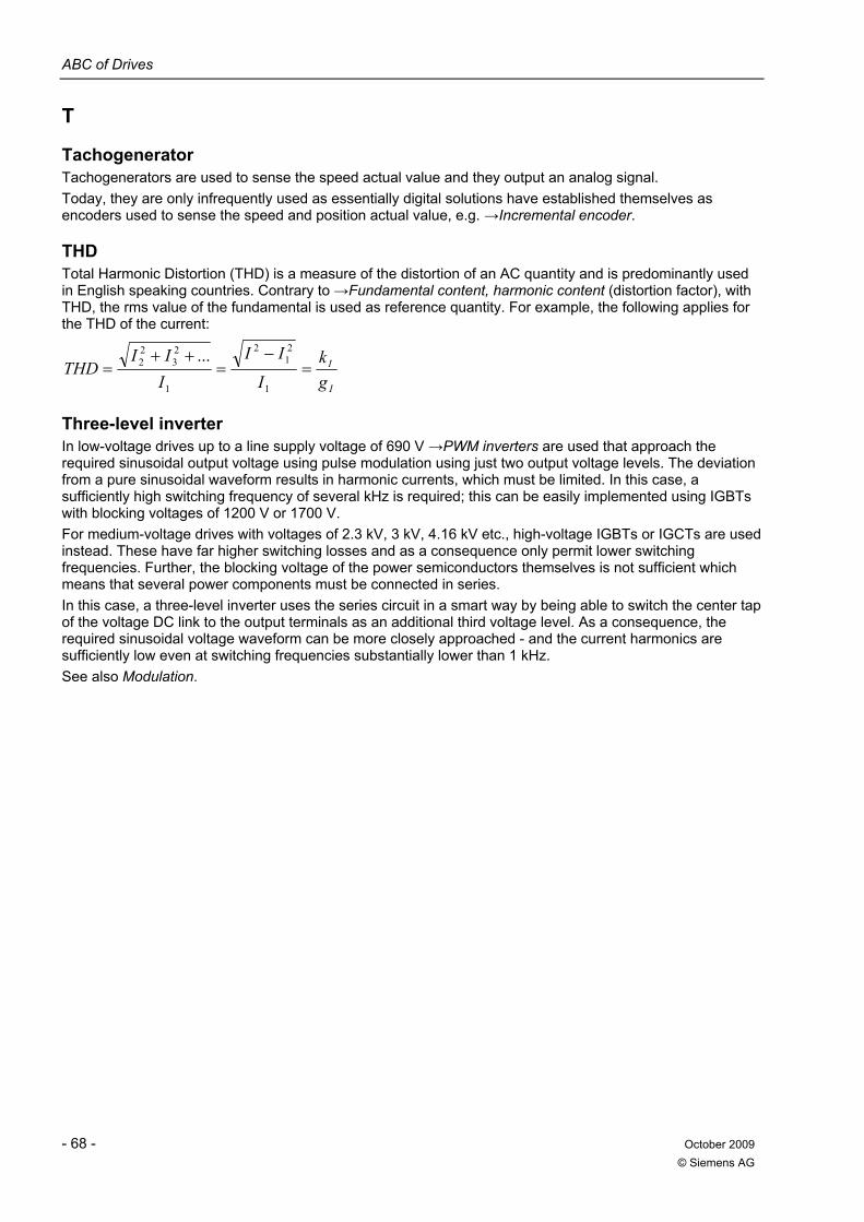
ABC of Drives
- 68 - October 2009 © Siemens AG
T
Tachogenerator Tachogenerators are used to sense the speed actual value and they output an analog signal. Today, they are only infrequently used as essentially digital solutions have established themselves as encoders used to sense the speed and position actual value, e.g. →Incremental encoder.
THD Total Harmonic Distortion (THD) is a measure of the distortion of an AC quantity and is predominantly used in English speaking countries. Contrary to →Fundamental content, harmonic content (distortion factor), with THD, the rms value of the fundamental is used as reference quantity. For example, the following applies for the THD of the current:
I
I
gk
I
II
III
THD =−
=++
=1
21
2
1
23
22 ...
Three-level inverter In low-voltage drives up to a line supply voltage of 690 V →PWM inverters are used that approach the required sinusoidal output voltage using pulse modulation using just two output voltage levels. The deviation from a pure sinusoidal waveform results in harmonic currents, which must be limited. In this case, a sufficiently high switching frequency of several kHz is required; this can be easily implemented using IGBTs with blocking voltages of 1200 V or 1700 V. For medium-voltage drives with voltages of 2.3 kV, 3 kV, 4.16 kV etc., high-voltage IGBTs or IGCTs are used instead. These have far higher switching losses and as a consequence only permit lower switching frequencies. Further, the blocking voltage of the power semiconductors themselves is not sufficient which means that several power components must be connected in series. In this case, a three-level inverter uses the series circuit in a smart way by being able to switch the center tap of the voltage DC link to the output terminals as an additional third voltage level. As a consequence, the required sinusoidal voltage waveform can be more closely approached - and the current harmonics are sufficiently low even at switching frequencies substantially lower than 1 kHz. See also Modulation.
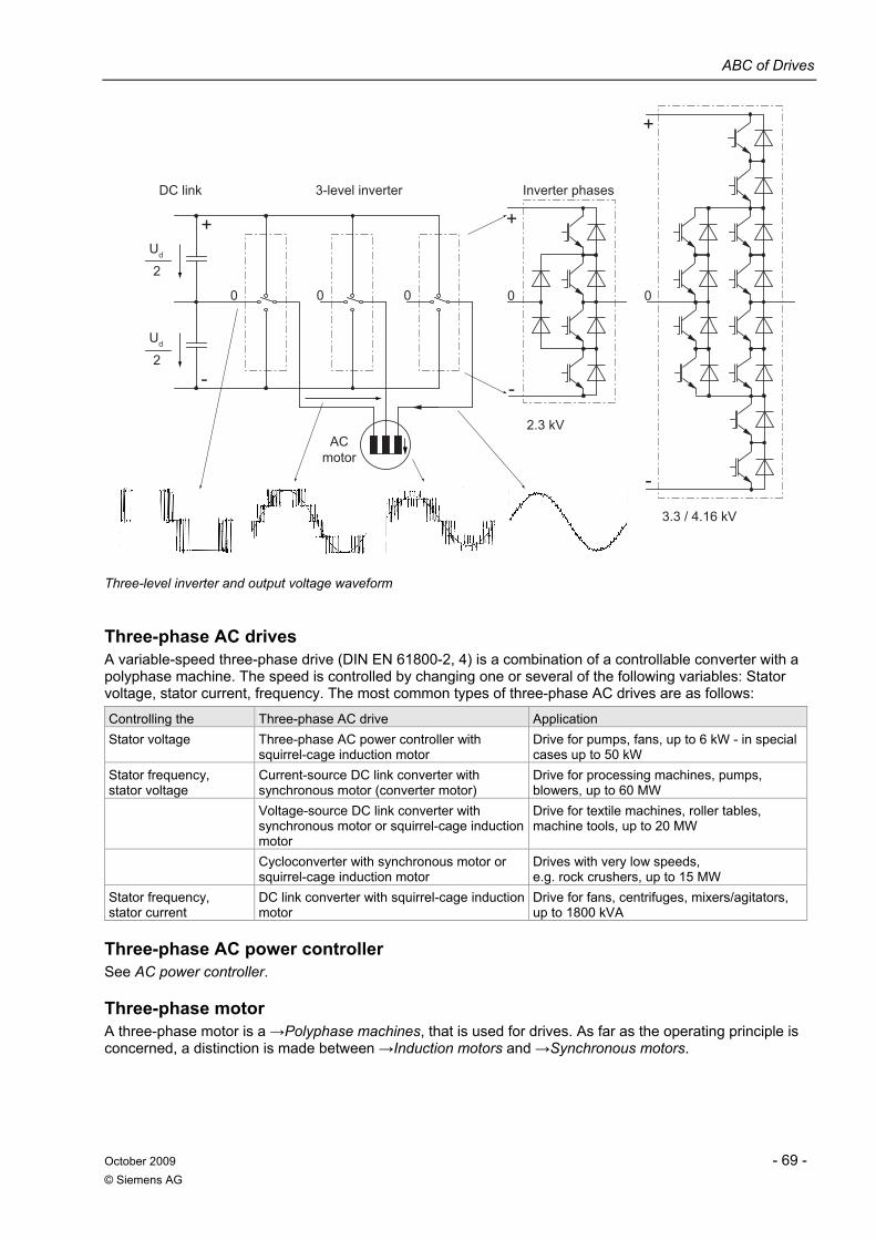
ABC of Drives
October 2009 - 69 - © Siemens AG
3.3 / 4.16 kV
2.3 kV
Inverter phases3-level inverterDC link
AC motor
0
-
+
0
2
Ud
2
0 0 0
-
+
-
+Ud
Three-level inverter and output voltage waveform
Three-phase AC drives A variable-speed three-phase drive (DIN EN 61800-2, 4) is a combination of a controllable converter with a polyphase machine. The speed is controlled by changing one or several of the following variables: Stator voltage, stator current, frequency. The most common types of three-phase AC drives are as follows:
Controlling the Three-phase AC drive Application Stator voltage Three-phase AC power controller with
squirrel-cage induction motor Drive for pumps, fans, up to 6 kW - in special cases up to 50 kW
Stator frequency, stator voltage
Current-source DC link converter with synchronous motor (converter motor)
Drive for processing machines, pumps, blowers, up to 60 MW
Voltage-source DC link converter with synchronous motor or squirrel-cage induction motor
Drive for textile machines, roller tables, machine tools, up to 20 MW
Cycloconverter with synchronous motor or squirrel-cage induction motor
Drives with very low speeds, e.g. rock crushers, up to 15 MW
Stator frequency, stator current
DC link converter with squirrel-cage induction motor
Drive for fans, centrifuges, mixers/agitators, up to 1800 kVA
Three-phase AC power controller See AC power controller.
Three-phase motor A three-phase motor is a →Polyphase machines, that is used for drives. As far as the operating principle is concerned, a distinction is made between →Induction motors and →Synchronous motors.
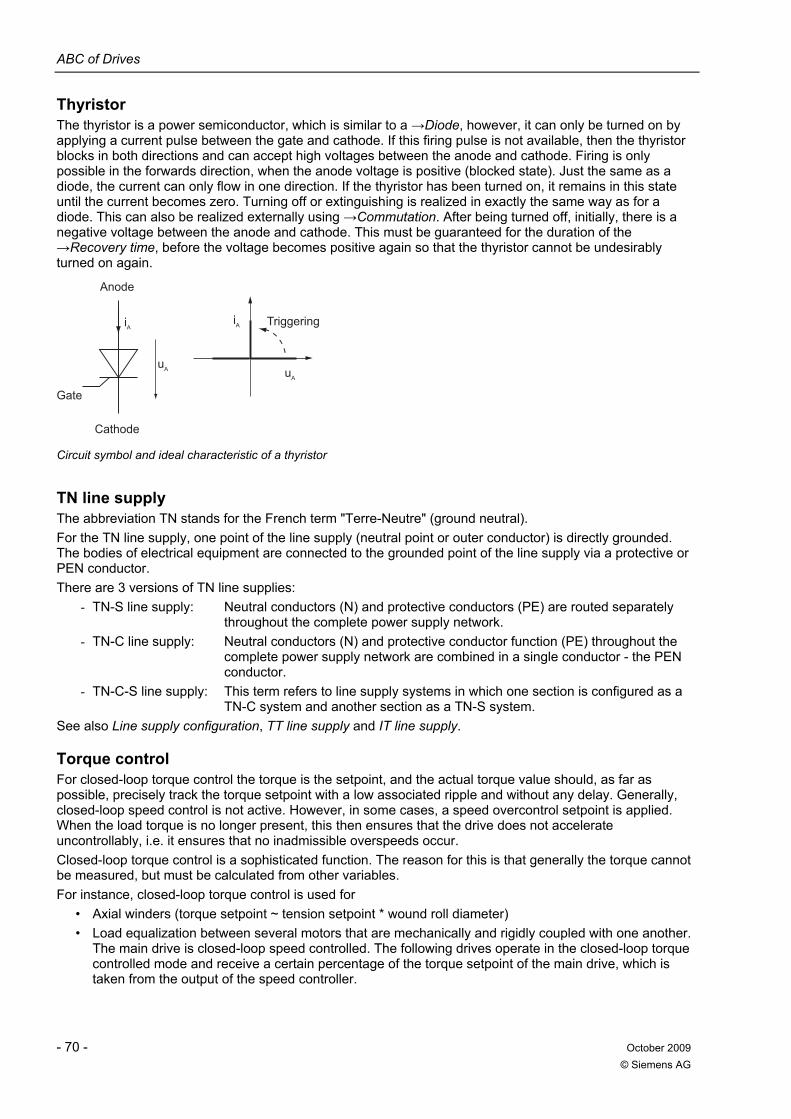
ABC of Drives
- 70 - October 2009 © Siemens AG
Thyristor The thyristor is a power semiconductor, which is similar to a →Diode, however, it can only be turned on by applying a current pulse between the gate and cathode. If this firing pulse is not available, then the thyristor blocks in both directions and can accept high voltages between the anode and cathode. Firing is only possible in the forwards direction, when the anode voltage is positive (blocked state). Just the same as a diode, the current can only flow in one direction. If the thyristor has been turned on, it remains in this state until the current becomes zero. Turning off or extinguishing is realized in exactly the same way as for a diode. This can also be realized externally using →Commutation. After being turned off, initially, there is a negative voltage between the anode and cathode. This must be guaranteed for the duration of the →Recovery time, before the voltage becomes positive again so that the thyristor cannot be undesirably turned on again.
Gate
Cathode
Triggering
Anode
AiAi
AuAu
Circuit symbol and ideal characteristic of a thyristor
TN line supply The abbreviation TN stands for the French term "Terre-Neutre" (ground neutral). For the TN line supply, one point of the line supply (neutral point or outer conductor) is directly grounded. The bodies of electrical equipment are connected to the grounded point of the line supply via a protective or PEN conductor. There are 3 versions of TN line supplies:
- TN-S line supply: Neutral conductors (N) and protective conductors (PE) are routed separately throughout the complete power supply network.
- TN-C line supply: Neutral conductors (N) and protective conductor function (PE) throughout the complete power supply network are combined in a single conductor - the PEN conductor.
- TN-C-S line supply: This term refers to line supply systems in which one section is configured as a TN-C system and another section as a TN-S system.
See also Line supply configuration, TT line supply and IT line supply.
Torque control For closed-loop torque control the torque is the setpoint, and the actual torque value should, as far as possible, precisely track the torque setpoint with a low associated ripple and without any delay. Generally, closed-loop speed control is not active. However, in some cases, a speed overcontrol setpoint is applied. When the load torque is no longer present, this then ensures that the drive does not accelerate uncontrollably, i.e. it ensures that no inadmissible overspeeds occur. Closed-loop torque control is a sophisticated function. The reason for this is that generally the torque cannot be measured, but must be calculated from other variables. For instance, closed-loop torque control is used for
• Axial winders (torque setpoint ~ tension setpoint * wound roll diameter) • Load equalization between several motors that are mechanically and rigidly coupled with one another.
The main drive is closed-loop speed controlled. The following drives operate in the closed-loop torque controlled mode and receive a certain percentage of the torque setpoint of the main drive, which is taken from the output of the speed controller.
ABC of Drives
October 2009 - 71 - © Siemens AG
Torque motor Torque motors are slow-running synchronous or induction motors with a high torque. Siemens torque motors are synchronous motors with liquid cooling (see Synchronous servomotor). They have a hollow shaft and are available as either built-in motors or complete motors. The torque motors comprise a stator and a rotor with permanent magnets. Siemens torque motors have the following properties: High number of pole pairs, high operating and standstill torques, low speeds, good dynamic properties. They have an extremely compact, space-saving design and are predestined for gearless, space-saving directly-coupled drives.
Torque-free interval For a double-way converter, the torque-free interval is the period of time during which current does not flow through the motor while reversing and therefore no torque is generated. In the case of one-way converters, it is the duration of the armature or field circuit reversal and in the case of double-way converters in a circulating current-free inverse parallel connection, it is the duration of the changeover controlled by the sequential logic stage. See also Inverse parallel connection.
Totally Integrated Automation (TIA) Tailored to individual customer requirements, Totally Integrated Automation can be used to implement industry-specific automation solutions that boost productivity and provide a high degree of investment security. Totally Integrated Automation is an integrated, seamless solution platform for all sectors from a single source. As a consequence, TIA supports companies when it comes to optimizing their production, process and plant operations. Totally Integrated Automation is based on the Siemens philosophy aimed at continuously further developing products, services and application know-how in a future-orientated way. Lower engineering costs when generating automation solutions, lower life-cycle costs when operating plants and systems, and significantly shorter time to market result in a significant increase in productivity and high security of investment.
Transient response When there is a step change at the input of a control loop, then the response of the output signal with respect to time - referred to the magnitude of the step change of the input signal - is known as the transient response.
TT line supply The abbreviation TT stands for the French term "Terre-Terre" (ground-ground). For TT line supplies, one point is directly grounded. The bodies of the electrical equipment are connected individually to ground or to the central ground point. The influence of the grounding resistance between the grounded points of the line supply and the potential of the separately grounded equipment must be taken into consideration. With converter technology, when using TT line supplies, please take into consideration that the effect of conventional line filters can be undefined as a result of the floating reference point. See also Line supply configuration, TN line supply and IT line supply.
ABC of Drives
- 72 - October 2009 © Siemens AG
V
Vector control Vector control is a high-performance control type for induction motors. It is based on a precise model calculation of the motor and two current components that simulate and accurately control the flux and torque by means of software-based algorithms. This means that speed and torque setpoints can be precisely maintained and limited with superior dynamic response. There are two types of vector control: Frequency control (sensorless vector control) and speed-torque control with speed feedback (→Encoder). See also Field-oriented control.
V/f control Control technique for →Induction motors, where the voltage amplitude U is specified as a function of the actual motor frequency f. In this case, an approximate motor model (see Model) is used, where the quotient V/f is proportional to the torque that can be achieved. The V/f characteristic can be adjusted. The most usual characteristic types are those with a constant torque or a square-law characteristic for pumps and fans. The following measures improve the properties of V/f control:
• Slip compensation maintains the speed constant during load changes using a load current-dependent frequency boost. The slip compensation becomes effective from approx. 10 % of the rated motor speed. This therefore allows a speed holding accuracy of approx. (0.2 x rated slip) to be achieved. The rated slip is, e.g. for motors from 30 KW and above, approx. ≤1.5 %.
• FCC control (Flux Current Control, extended i*R compensation) also improves the speed holding accuracy during load changes. FCC adapts the voltage - and therefore the rotor flux - to the load.
• The voltage increase at low frequencies ("boost") optimizes the starting behavior. • Resonance damping attenuates electromechanical oscillations in the range between 10 and 40 Hz for
induction motors up to approx. 160 kW. • The current limiting control is used as stall protection.
V/f control is preferably used in the following applications: • For applications with low to average requirements placed on the dynamic response, speed control
range and accuracy. • For →Group drives (several drives connected to a converter), also with "group synchronous operation"
(with reluctance motors in the textile sector). • If commissioning is to be as simple as possible and high parameter ruggedness is required.
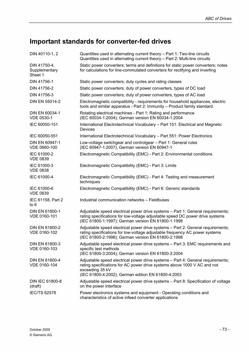
ABC of Drives
October 2009 - 73 - © Siemens AG
Important standards for converter-fed drives DIN 40110-1, 2 Quantities used in alternating current theory – Part 1: Two-line circuits
Quantities used in alternating current theory – Part 2: Multi-line circuits DIN 41750-4, Supplementary Sheet 1
Static power converters; terms and definitions for static power converters; notes for calculations for line-commutated converters for rectifying and inverting
DIN 41756-1 Static power converters; duty cycles and rating classes DIN 41756-2 Static power converters; duty of power converters, types of DC load DIN 41756-3 Static power converters; duty of power converters, types of AC load DIN EN 55014-2 Electromagnetic compatibility - requirements for household appliances, electric
tools and similar apparatus - Part 2: Immunity – Product family standard. DIN EN 60034-1 VDE 0530-1
Rotating electrical machines - Part 1: Rating and performance (IEC 60034-1:2004); German version EN 60034-1:2004
IEC 60050-151 International Electrotechnical Vocabulary – Part 151: Electrical and Magnetic Devices
IEC 60050-551 International Electrotechnical Vocabulary – Part 551: Power Electronics DIN EN 60947-1 VDE 0660-100
Low-voltage switchgear and controlgear – Part 1: General rules (IEC 60947-1:2007); German version EN 60947-1
IEC 61000-2 VDE 0839
Electromagnetic Compatibility (EMC) - Part 2: Environmental conditions
IEC 61000-3 VDE 0838
Electromagnetic Compatibility (EMC) - Part 3: Limits
IEC 61000-4 Electromagnetic Compatibility (EMC) - Part 4: Testing and measurement techniques
IEC 61000-6 VDE 0839
Electromagnetic Compatibility (EMC) - Part 6: Generic standards
IEC 61158, Part 2 to 6
Industrial communication networks – Fieldbuses
DIN EN 61800-1 VDE 0160-101
Adjustable speed electrical power drive systems – Part 1: General requirements; rating specifications for low-voltage adjustable speed DC power drive systems (IEC 61800-1:1997); German version EN 61800-1:1998
DIN EN 61800-2 VDE 0160-102
Adjustable speed electrical power drive systems – Part 2: General requirements; rating specifications for low-voltage adjustable frequency AC power systems (IEC 61800-2:1998); German version EN 61800-2:1998
DIN EN 61800-3 VDE 0160-103
Adjustable speed electrical power drive systems – Part 3: EMC requirements and specific test methods (IEC 61800-3:2004); German version EN 61800-3:2004
DIN EN 61800-4 VDE 0160-104
Adjustable speed electrical power drive systems – Part 4: General requirements; rating specifications for AC power drive systems above 1000 V AC and not exceeding 35 kV (IEC 61800-4:2002); German edition EN 61800-4:2003
DIN IEC 61800-8 (draft)
Adjustable speed electrical power drive systems – Part 8: Specification of voltage on the power interface
IEC/TS 62578 Power electronics systems and equipment - Operating conditions and characteristics of active infeed converter applications
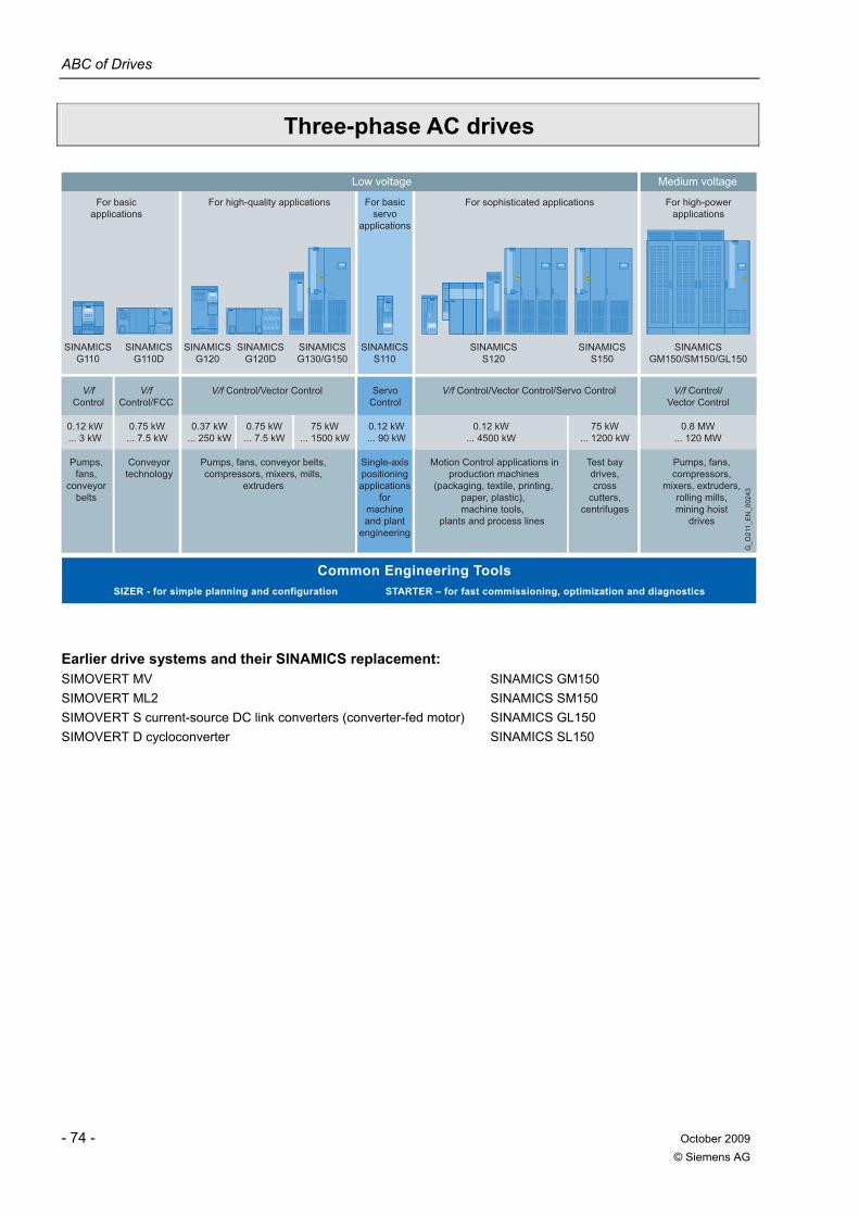
ABC of Drives
- 74 - October 2009 © Siemens AG
Three-phase AC drives
V/fControl
V/fControl/FCC
Motion Control applications inproduction machines
(packaging, textile, printing,paper, plastic),machine tools,
plants and process lines
0.12 kW ... 3 kW
Pumps, fans,
conveyor belts
Conveyor technology
SIZER - for simple planning and configuration STARTER – for fast commissioning, optimization and diagnostics
Common Engineering Tools
V/f Control/Vector Control/Servo Control
0.12 kW ... 4500 kW
75 kW ... 1200 kW
0.12 kW ... 90 kW
Servo Control
Single-axis positioning applications
for machineand plant
engineering
Test baydrives,cross
cutters,centrifuges
V/f Control/Vector Control
Pumps, fans,compressors,
mixers, extruders,rolling mills,mining hoist
drives
0.8 MW... 120 MW
SINAMICS GM150/SM150/GL150
For high-powerapplications
SINAMICS S120
SINAMICS S150
SINAMICS S110
SINAMICS G110
SINAMICS G110D
For basicapplications
Low voltage
For sophisticated applicationsFor basic servo
applications
Medium voltage
V/f Control/Vector Control
0.37 kW ... 250 kW
0.75 kW ... 7.5 kW
0.75 kW ... 7.5 kW
75 kW ... 1500 kW
SINAMICS G130/G150
SINAMICS G120
SINAMICS G120D
For high-quality applications
Pumps, fans, conveyor belts, compressors, mixers, mills,
extruders
G_D
211_
EN
_002
43
Earlier drive systems and their SINAMICS replacement: SIMOVERT MV SINAMICS GM150 SIMOVERT ML2 SINAMICS SM150 SIMOVERT S current-source DC link converters (converter-fed motor) SINAMICS GL150 SIMOVERT D cycloconverter SINAMICS SL150
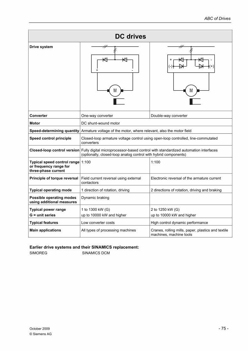
ABC of Drives
October 2009 - 75 - © Siemens AG
DC drives Drive system
M
+ -
M
+ -
(-) (+)
Converter One-way converter Double-way converter
Motor DC shunt-wound motor
Speed-determining quantity Armature voltage of the motor, where relevant, also the motor field
Speed control principle Closed-loop armature voltage control using open-loop controlled, line-commutated converters
Closed-loop control version Fully digital microprocessor-based control with standardized automation interfaces (optionally, closed-loop analog control with hybrid components)
Typical speed control range or frequency range for three-phase current
1:100 1:100
Principle of torque reversal Field current reversal using external contactors
Electronic reversal of the armature current
Typical operating mode 1 direction of rotation, driving 2 directions of rotation, driving and braking
Possible operating modes using additional measures
Dynamic braking
Typical power range G = unit series
1 to 1300 kW (G) up to 10000 kW and higher
2 to 1250 kW (G) up to 10000 kW and higher
Typical features Low converter costs High control dynamic performance
Main applications All types of processing machines Cranes, rolling mills, paper, plastics and textile machines, machine tools
Earlier drive systems and their SINAMICS replacement: SIMOREG SINAMICS DCM
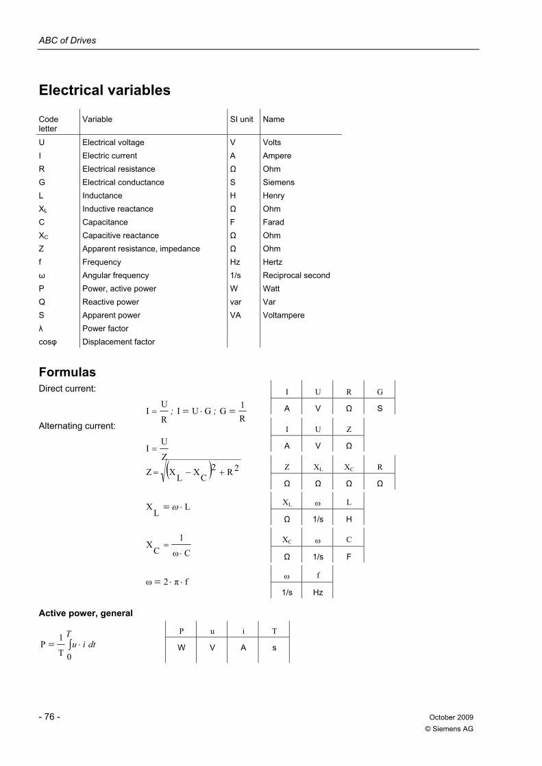
ABC of Drives
- 76 - October 2009 © Siemens AG
Electrical variables
Code letter
Variable SI unit Name
U Electrical voltage V Volts I Electric current A Ampere R Electrical resistance Ω Ohm G Electrical conductance S Siemens L Inductance H Henry XL Inductive reactance Ω Ohm C Capacitance F Farad XC Capacitive reactance Ω Ohm Z Apparent resistance, impedance Ω Ohm f Frequency Hz Hertz ω Angular frequency 1/s Reciprocal second P Power, active power W Watt Q Reactive power var Var S Apparent power VA Voltampere λ Power factor cosφ Displacement factor
Formulas Direct current:
I
U
R
G
R
UI = ; GUI ⋅= ;
R1
G = A V Ω S Alternating current:
I
U
Z
Z
UI = A V Ω
Z XL XC R ( ) 2R2CXLX Z +−=
Ω Ω Ω Ω
XL ω L LL
X ⋅= ω Ω 1/s H
XC ω C
Cω
1C
X⋅
= Ω 1/s F
ω f fπ2ω ⋅⋅=
1/s Hz
Active power, general
P u i T
∫= ⋅T
dtiu0T
1P W V A s
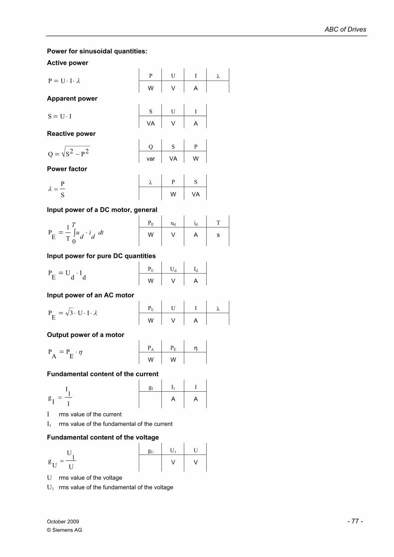
ABC of Drives
October 2009 - 77 - © Siemens AG
Power for sinusoidal quantities:
Active power
P U I λ λ⋅⋅= IUP
W V A
Apparent power
S U I IUS ⋅=
VA V A
Reactive power
Q S P 2P2SQ −=
var VA W
Power factor
λ P S
S
P=λ
W VA
Input power of a DC motor, general
PE ud id T
∫= ⋅T
dtdidu0T
1E
P W V A s
Input power for pure DC quantities
PE Ud Id d
Id
UE
P ⋅= W V A
Input power of an AC motor
PE U I λ λ⋅⋅⋅= IU3
EP
W V A
Output power of a motor
PA PE η η⋅=E
PA
P W W
Fundamental content of the current
gI I1 I
I1
I
Ig = A A
I rms value of the current I1 rms value of the fundamental of the current
Fundamental content of the voltage
gU U1 U
U1
U
Ug = V V
U rms value of the voltage U1 rms value of the fundamental of the voltage
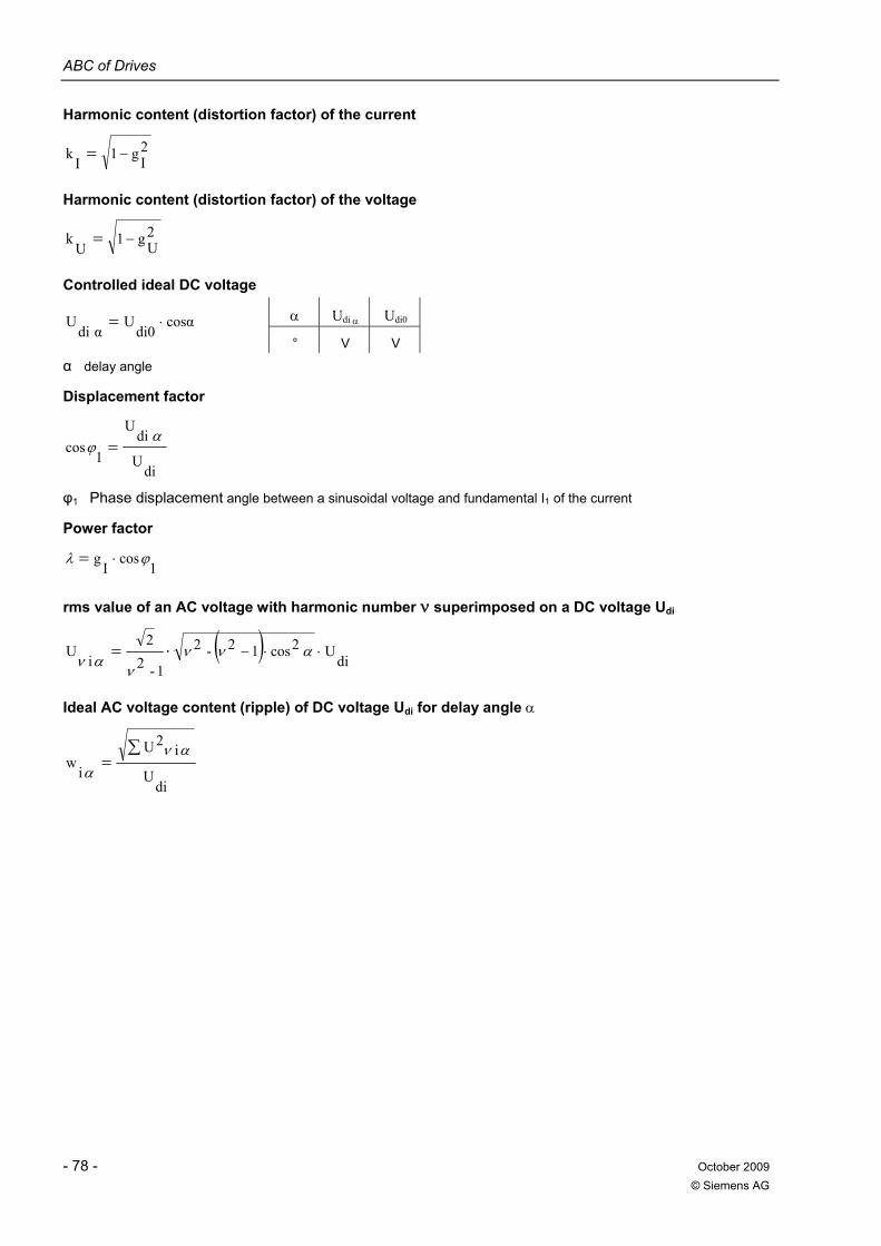
ABC of Drives
- 78 - October 2009 © Siemens AG
Harmonic content (distortion factor) of the current
2Ig1
Ik −=
Harmonic content (distortion factor) of the voltage
2Ug1
Uk −=
Controlled ideal DC voltage
α Udi α Udi0 cosαdi0
Uαdi
U ⋅= ° V V
α delay angle
Displacement factor
diU
diU
1cos
αϕ =
φ1 Phase displacement angle between a sinusoidal voltage and fundamental I1 of the current
Power factor
1cos
Ig ϕλ ⋅=
rms value of an AC voltage with harmonic number ν superimposed on a DC voltage Udi
( )di
U2cos12-2
1-22
iU ⋅⋅−⋅= ανν
ναν
Ideal AC voltage content (ripple) of DC voltage Udi for delay angle α
diU
i2U
iw
∑=
ανα
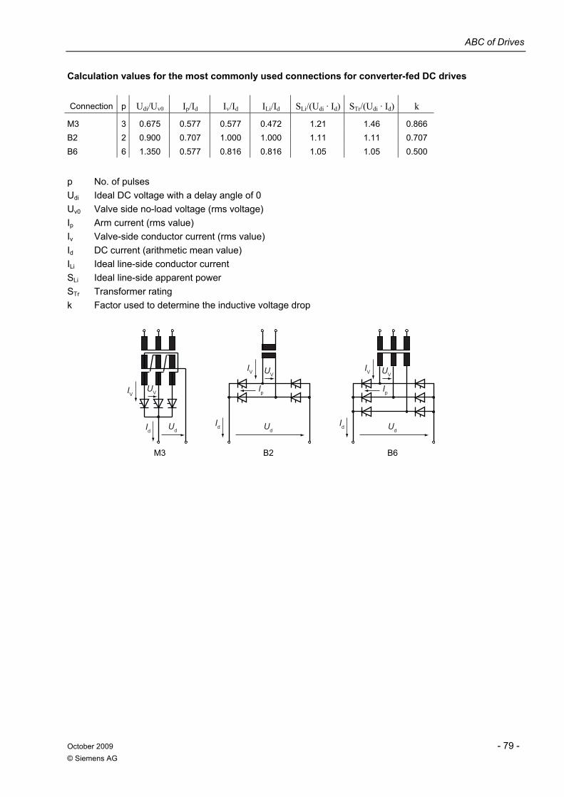
ABC of Drives
October 2009 - 79 - © Siemens AG
Calculation values for the most commonly used connections for converter-fed DC drives
Connection p Udi/Uv0 Ip/Id Iv/Id ILi/Id SLi/(Udi · Id) STr/(Udi · Id) k
M3 3 0.675 0.577 0.577 0.472 1.21 1.46 0.866 B2 2 0.900 0.707 1.000 1.000 1.11 1.11 0.707 B6 6 1.350 0.577 0.816 0.816 1.05 1.05 0.500
p No. of pulses Udi Ideal DC voltage with a delay angle of 0 Uv0 Valve side no-load voltage (rms voltage) Ip Arm current (rms value) Iv Valve-side conductor current (rms value) Id DC current (arithmetic mean value) ILi Ideal line-side conductor current SLi Ideal line-side apparent power STr Transformer rating k Factor used to determine the inductive voltage drop
B2
UdUd
IV
IV
UV
UV
IdId
Ip
B6
Ud
IV UV
Id
Ip
M3
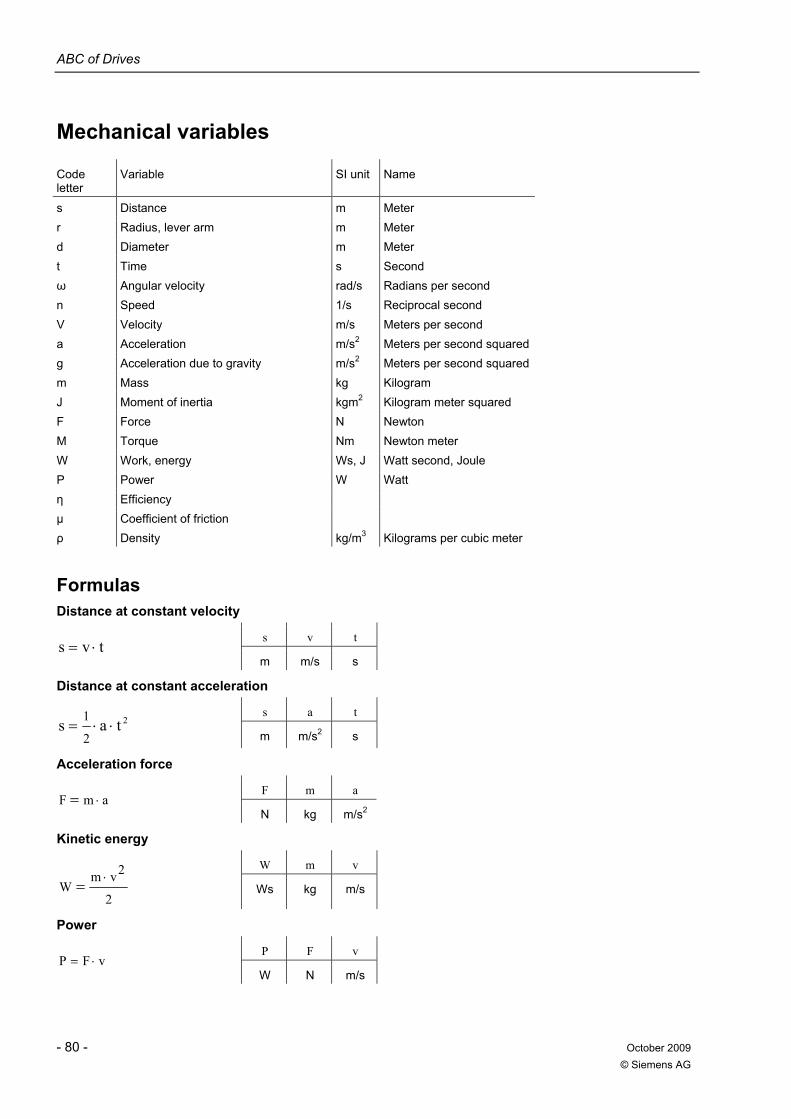
ABC of Drives
- 80 - October 2009 © Siemens AG
Mechanical variables
Code letter
Variable SI unit Name
s Distance m Meter r Radius, lever arm m Meter d Diameter m Meter t Time s Second ω Angular velocity rad/s Radians per second n Speed 1/s Reciprocal second V Velocity m/s Meters per second a Acceleration m/s2 Meters per second squaredg Acceleration due to gravity m/s2 Meters per second squaredm Mass kg Kilogram J Moment of inertia kgm2 Kilogram meter squared F Force N Newton M Torque Nm Newton meter W Work, energy Ws, J Watt second, Joule P Power W Watt η Efficiency μ Coefficient of friction ρ Density kg/m3 Kilograms per cubic meter
Formulas Distance at constant velocity
s v t tvs ⋅=
m m/s s
Distance at constant acceleration
s a t 2tas
2
1⋅⋅=
m m/s2 s
Acceleration force
F m a amF ⋅=
N kg m/s2
Kinetic energy
W m v
2
2vmW
⋅= Ws kg m/s
Power
P F v vFP ⋅=
W N m/s
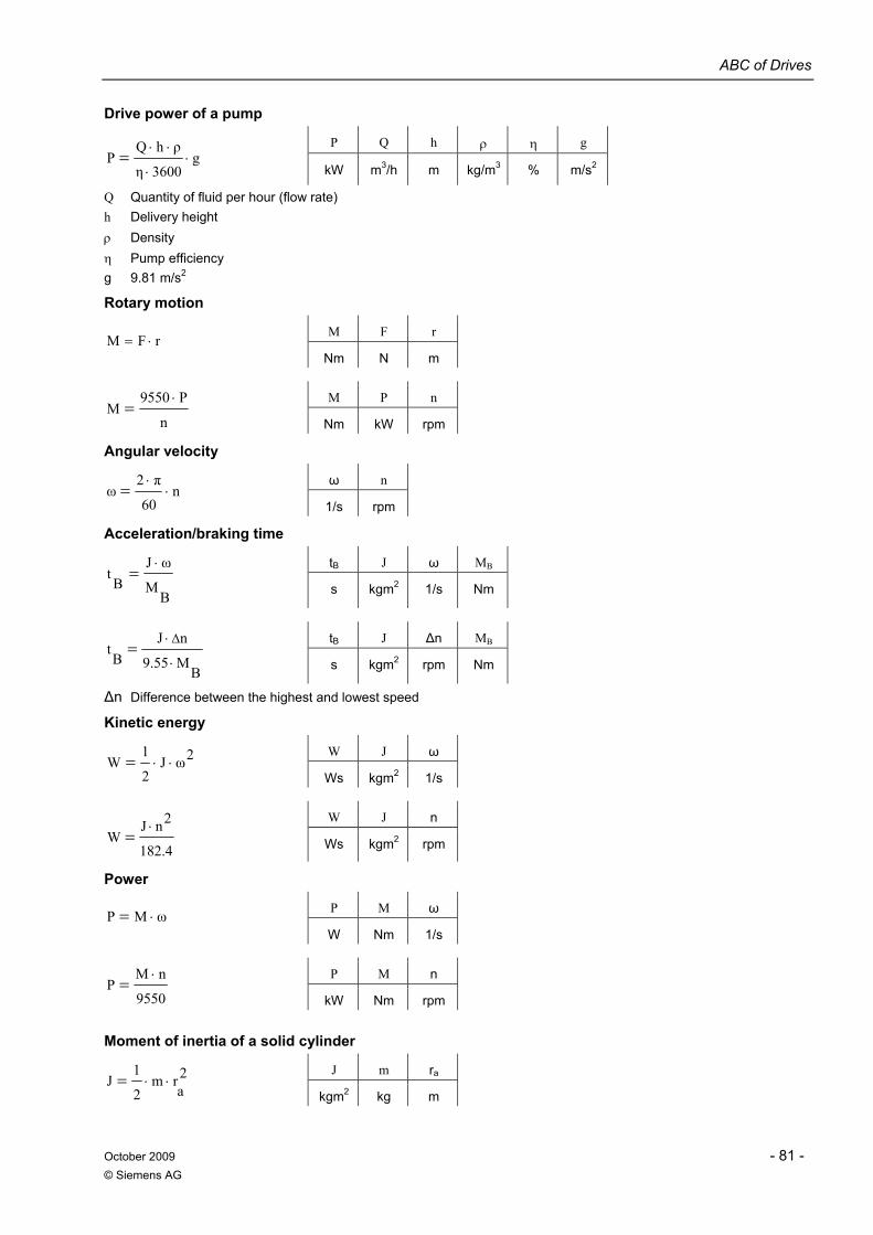
ABC of Drives
October 2009 - 81 - © Siemens AG
Drive power of a pump
P Q h ρ η g g
3600η
ρhQP ⋅
⋅
⋅⋅=
kW m3/h m kg/m3 % m/s2
Q Quantity of fluid per hour (flow rate) h Delivery height ρ Density η Pump efficiency g 9.81 m/s2
Rotary motion
M F r rFM ⋅=
Nm N m
M P n
n
P9550M
⋅=
Nm kW rpm
Angular velocity
ω n n
60
π2ω ⋅
⋅=
1/s rpm
Acceleration/braking time
tB J ω MB
BM
ωJB
t⋅
=
s kgm2 1/s Nm
tB J Δn MB
BM9.55
nJB
tΔ
⋅
⋅=
s kgm2 rpm Nm
Δn Difference between the highest and lowest speed
Kinetic energy
W J ω 2ωJ2
1W ⋅⋅=
Ws kgm2 1/s
W J n
182.4
2nJW
⋅= Ws kgm2 rpm
Power
P M ω ωMP ⋅= W Nm 1/s
P M n
9550
nMP
⋅=
kW Nm rpm
Moment of inertia of a solid cylinder
J m ra 2a
rm2
1J ⋅⋅=
kgm2 kg m
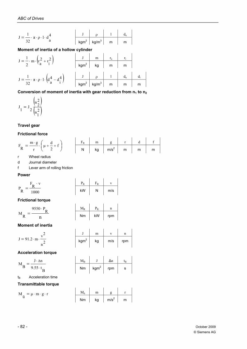
ABC of Drives
- 82 - October 2009 © Siemens AG
J ρ l da 4a
dlρπ32
1J ⋅⋅⋅⋅=
kgm2 kg/m3 m m
Moment of inertia of a hollow cylinder
J m ra ri ( )2ir
2arm
2
1J +⋅⋅=
kgm2 kg m m
J ρ l da di ( )4id4
adlρπ32
1J −⋅⋅⋅⋅=
kgm2 kg/m3 m m m
Conversion of moment of inertia with gear reduction from n1 to n2
( )( )2
1n
22n
2J
1J =
Travel gear
Frictional force
FR m g r d f ⎟⎠⎞
⎜⎝⎛= ++⋅
⋅f
2d
μr
gmR
F N kg m/s2 m m m
r Wheel radius d Journal diameter f Lever arm of rolling friction
Power
PR FR v
1000
vR
F
RP
⋅=
kW N m/s
Frictional torque
MR PR n
nR
P9550
RM
⋅=
Nm kW rpm
Moment of inertia
J m v n
2n
2vm91.2J ⋅⋅= kgm2 kg m/s rpm
Acceleration torque
MB J Δn tB
Bt9.55
nJB
MΔ
⋅
⋅=
Nm kgm2 rpm s
tB Acceleration time
Transmittable torque
Mü m g r rgmμü
M ⋅⋅⋅= Nm kg m/s2 m

ABC of Drives
October 2009 - 83 - © Siemens AG

ABC of Drives
- 84 - October 2009 © Siemens AG


www.siemens.com/sinamics
Siemens AGIndustry SectorDrive Technologies DivisionPostfach 48 48 484890026 NürnbergGERMANY
Subject to change without prior noticeOrder No. E86060-T5502-A101-A1-76003P.8222.10.06 / Dispo 18401BU 0410 2.0 E 92 ENPrinted in Germany © Siemens AG 2009
The information provided in this brochure contains merely general descriptions or performance characteristics which in case of actual use do not always apply as described or which may change as a result of further development of the products. An obligation to provide the respective characteristics shall only exist if expressly agreed in the terms of contract.
All product designations may be trademarks or product names of Siemens AG or supplier companies whose use by third parties for their own purposes could violate the rights of the owners.
Token fee: 5.00 €
© Siemens AG 2010