aashtoware brr training · 2 span prestressed concrete i-beam with a composite concrete deck by ......
TRANSCRIPT

AASHTOWare BrR Training
Modeling and Analysis of a
2 Span Prestressed Concrete I-Beam with a
Composite Concrete Deck
By
OSE

- 1 -
Contents
PLAN SET……………………………………………………………………………………………………………………………………………. - 2 -
CREATE A BRIDGE MODEL ................................................................................................................... - 9 -
Description ...................................................................................................................................... - 9 -
BRIDGE WORKSPACE ......................................................................................................................... - 10 -
Materials ....................................................................................................................................... - 11 -
Select Structural Steel ................................................................................................................ - 11 -
Select Concrete .......................................................................................................................... - 12 -
Select Reinforcing Steel ............................................................................................................. - 13 -
Select Prestress Strands ............................................................................................................. - 14 -
Beam Shapes ................................................................................................................................. - 15 -
Selecting I-Beam Shapes ............................................................................................................ - 15 -
Select Angle Shapes ................................................................................................................... - 16 -
Appurtenances .............................................................................................................................. - 17 -
Diaphragm Definition..................................................................................................................... - 18 -
Factors .......................................................................................................................................... - 19 -
SUPERSTRUCTURE DEFINITIONS ........................................................................................................ - 20 -
Load Case Description .................................................................................................................... - 21 -
Framing Plan .................................................................................................................................. - 22 -
Diaphragm layout .......................................................................................................................... - 23 -
Structure Typical Section ............................................................................................................... - 26 -
Stress Limits .................................................................................................................................. - 32 -
Prestress Properties ....................................................................................................................... - 33 -
Shear Reinforcement Definitions ................................................................................................... - 34 -
Member Definition ........................................................................................................................ - 35 -
Default Materials ........................................................................................................................... - 37 -
Impact/Dynamic Load Allowance ................................................................................................... - 37 -
Beam Details ................................................................................................................................. - 38 -
Mild Steel Layout ........................................................................................................................... - 40 -
Strand Layout ................................................................................................................................ - 41 -
Deck Profile ................................................................................................................................... - 45 -
Haunch Profile ............................................................................................................................... - 46 -
Shear Reinforcement Ranges ......................................................................................................... - 47 -
Copying Member Alternatives ....................................................................................................... - 48 -
Linking Members ........................................................................................................................... - 50 -
Deck Profile [Revisited] .................................................................................................................. - 51 -
Live Load Distribution Factors ........................................................................................................ - 53 -
Model Validation ........................................................................................................................... - 54 -
Bridge Alternatives ........................................................................................................................ - 55 -
RUNNING ANALYSIS........................................................................................................................... - 57 -

- 2 -
MODELING DETERIORATION .............................................................................................................. - 62 -
Removing Deteriorated Prestressed Strands .................................................................................. - 62 -
Unlinking/Copying Member Alternatives ................................................................................... - 63 -
Revise Strand Layout.................................................................................................................. - 65 -
APPENDIX .......................................................................................................................................... - 67 -

- 3 -
- 4 -

- 5 -

- 6 -

- 7 -

- 8 -

- 9 -
CREATE A BRIDGE MODEL Click the create bridge icon near the upper left corner to create a new bridge.
Description The Structure File Number (SFN) should be entered in the Bridge ID and NBI Structure ID fields. The County-Inventory
Route-Straight Line Mileage is entered into the Name field. For this training, the bridge is located in Lucas County
on US-24 at SLM 8.47. Location, Facility Carried, and Feat. Intersected should all be entered to match SMS data.
Although not required, selecting the appropriate main structure type will simplify the bridge workspace by removing
some structure type specific folders. More detail is provided on the ODOT Structures website in the Bridge
Management Section. Links provided in the appendix. For help, the user can always press F1 at any point to get
help with the currently opened window.
Create Bridge
Structure
Type
SFN
Inventory
Route
Bridge
Name
Information
Entered
Should
Match SMS
- 10 -
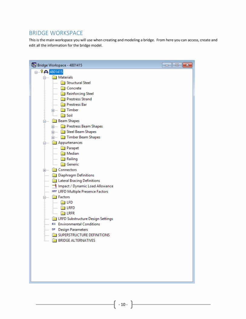
BRIDGE WORKSPACE This is the main workspace you will use when creating and modeling a bridge. From here you can access, create and
edit all the information for the bridge model.

- 11 -
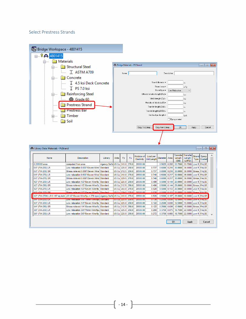
Materials The materials folder allows you to create material definitions for use within the model. For most of the selections
within BrR you will either be able to define a specific material or simply select a pre-defined material from the library.
For this training you will need to select A709 structural steel, 4.5 ksi concrete, PS 7.0 ksi concrete, Grade 60
reinforcing steel (epoxy coated) and ½” (7W-270K) LR 0.167 sq inch prestress strands. Each material can be
populated by double clicking the requisite folder and clicking Copy from Library. Select the material needed for the
bridge and then click OK.
Select Structural Steel

- 12 -
Select Concrete

- 13 -
Select Reinforcing Steel
- 14 -
Select Prestress Strands
- 15 -
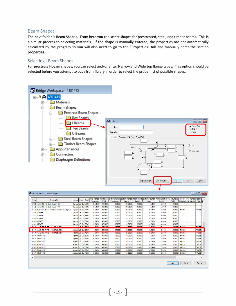
Beam Shapes The next folder is Beam Shapes. From here you can select shapes for prestressed, steel, and timber beams. This is
a similar process to selecting materials. If the shape is manually entered, the properties are not automatically
calculated by the program so you will also need to go to the “Properties” tab and manually enter the section
properties.
Selecting I-Beam Shapes
For prestress I-beam shapes, you can select and/or enter Narrow and Wide top flange types. This option should be
selected before you attempt to copy from library in order to select the proper list of possible shapes.

- 16 -
Select Angle Shapes

- 17 -
Appurtenances This folder allows you to define parapets, medians, railings, and/or generic shapes. When defining parapets, you
can select from a pre-defined list of shapes by using the library. For this training we will select the shape shown in
the figure below. You can revise the values that are populated when selecting a pre-defined parapet shape if needed.
Make sure you have entered a unit weight for the material used, otherwise the program will not include the weight
in the analysis.
Additional weight can be
added for VPF and other
rails or misc. attachments
Unit Weight
Add a 6 ft Vandal
Protection fence.

- 18 -
Diaphragm Definition The Diaphragm folder allows you to create the definitions for multiple types of diaphragms such as concrete, steel
channel, and different steel angle types. In this example we have a X-frame type of diaphragm with no top member,
so you will first select a “Type 1” diaphragm. From here assign shapes and materials to each of the members
required. Note: We don’t need AB, so set this to “—None--”. In the next section, you will need to define your
connection types and locations measured in inches from top and bottom or the web. The diaphragm weight is not
automatically calculated so you will need to manually calculate the weight and enter it later in Framing Plan Detail.

- 19 -
Factors From the Factors folder, you can select the factors for your analysis using the Copy from Library option. You can
select factors for each code as needed. For load rating purposes, select the latest specifications for LFD and LRFD.

- 20 -
SUPERSTRUCTURE DEFINITIONS Double clicking the “SUPERSTRUCTURE DEFINITONS” folder will give you the option to select your superstructure
definition type. You can choose from a Girder System, Girder Line, Floor System, Truss, RC Slab, and Multi-Cell Box
superstructures. For this training we will be analyzing a 2 span prestress concrete I-beam. Select the Girder System
option and click OK. Set the number of spans to 1 and then set the number of girders, enter the span length, and
select the member type. When modeling a multi-span prestressed concrete superstructure, we will split and model
spans as their own simple span superstructure models. Enter the data to match the figures shown below.
Deck
Type
Member
Types
Deck
Type
Span Lengths
(bearing/bearing)

- 21 -
Load Case Description From this window, you can select your required load cases. There is an option to add the basic load cases by clicking
“Add Default Load Case Descriptions” button. This will add DC1, DC2, DW, and SIP Forms. These can be renamed
or deleted as necessary, or you can create more, depending on your needs. It can be beneficial to create individual
load cases for different utilities or additional wearing surfaces to clearly identify the additional load that is being
applied.

- 22 -
Framing Plan The framing plan detail allows you to enter the girder spacing, skew, diaphragms, and lateral bracing. The skew can
be either a positive or negative number depending on if it’s a left forward (+) or right forward (-) skew. The girder
spacing can be entered separately for each girder bay. If the girders are splayed you will need to set the Girder
Spacing Orientation to Along Support to enter variable girder spacing. You can also hover the mouse pointer over
most input values and a box will display the value converted to other units. Enter the data to match the figures
shown below.

- 23 -
Diaphragm layout The diaphragm layout can, in some cases, be the most time-consuming part of modeling a bridge. This example
should give you some of the basic strategies on how to place diaphragms more efficiently. To assign the layout for
the diaphragms you must have the framing plan details window open and then click the Diaphragms Tab. From here,
you can manually enter the location, spacing information, weight and assign a definition for each diaphragm in a
bay. You may only enter information into one bay at a time. (See the included “Bridge Modeling Information” on
page 8 for more details on the input data shown.)

- 24 -
Diaphragm layout (Cont’d) Once you have the diaphragm information correctly entered for Bay 1, you can utilize the “Copy Bay To…” button
and this will copy your currently selected bay to any of the other bays. Select all the bays and hit apply. You will
receive a notification stating which bays have been revised. You can also use the dropdown and select the various
bays and view and/or revise any input data if necessary.

- 25 -
Diaphragm layout (Cont’d)
One way to visually check your input data is to return to the Bridge Workspace window and to right click the Framing
Plan Detail and select Schematic. By adjusting the window size or using the zoom in/out tool, you can see what the
framing plan looks like. By performing this step, you can check your skew, beam spacing and diaphragm locations.
The final framing plan schematic should look like this.

- 26 -
Structure Typical Section Next, we will skip down to the Structure Typical Section. Here you will define the width of the bridge deck, overhang
distance, thickness of the deck slab, location of the parapets and/or rails, lane position, and the wearing surface.
The deck tab allows you to enter the deck width by entering the distances from the left and right deck edges to the
reference line and the left overhang width. It is helpful to enter these values to set the reference line in the center
of the deck. This can allow you to easily define a vehicle path at the center of the bridge for non-standard gauge
vehicle analysis.
- 27 -
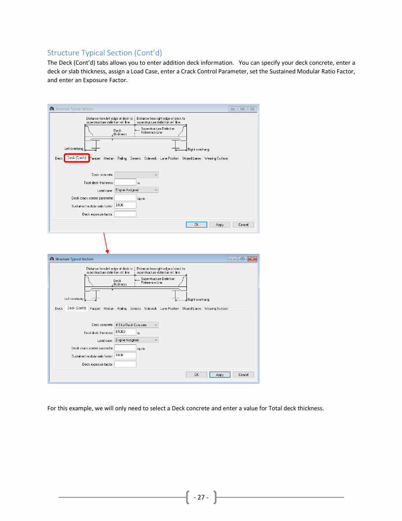
Structure Typical Section (Cont’d) The Deck (Cont’d) tabs allows you to enter addition deck information. You can specify your deck concrete, enter a
deck or slab thickness, assign a Load Case, enter a Crack Control Parameter, set the Sustained Modular Ratio Factor,
and enter an Exposure Factor.
For this example, we will only need to select a Deck concrete and enter a value for Total deck thickness.

- 28 -
Structure Typical Section (Cont’d) The Parapet tab allows you to enter barrier information. Click “New” to create a barrier. Assign the proper
definition, load case, and location information for any railing or barrier needed for the bridge. For this bridge you
can simply set the “Measure To” as Back and the left and right edges along with “Front Face Orientation” as shown
below.
This bridge does not contain a median, railing, or a sidewalk, so we can leave those tabs untouched for this model.

- 29 -
Structure Typical Section (Cont’d) For defining the Lane Position, it can be easily set by clicking the “Compute…” button at the bottom of the window.
Keep in mind that once the lane position is set, it will not automatically update with any changes to the Deck, Parapet,
Median, Railing or Sidewalk tabs. If any of those tabs are revised, the lane position must be recalculated.
- 30 -
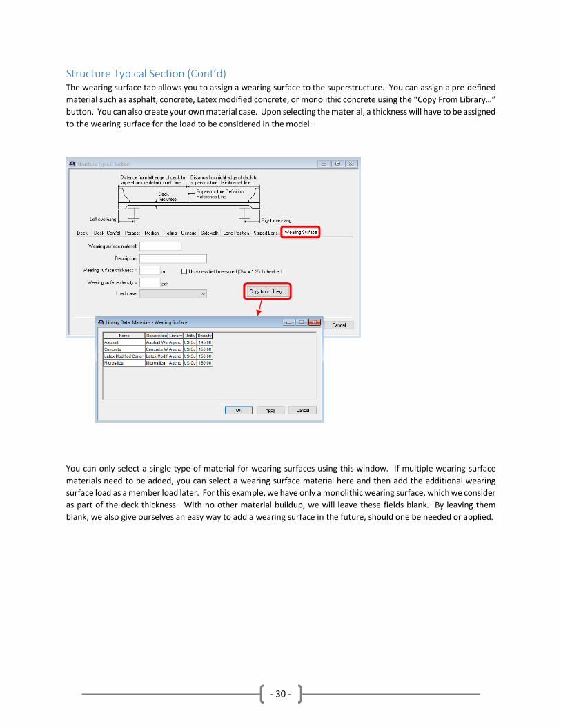
Structure Typical Section (Cont’d) The wearing surface tab allows you to assign a wearing surface to the superstructure. You can assign a pre-defined
material such as asphalt, concrete, Latex modified concrete, or monolithic concrete using the “Copy From Library…”
button. You can also create your own material case. Upon selecting the material, a thickness will have to be assigned
to the wearing surface for the load to be considered in the model.
You can only select a single type of material for wearing surfaces using this window. If multiple wearing surface
materials need to be added, you can select a wearing surface material here and then add the additional wearing
surface load as a member load later. For this example, we have only a monolithic wearing surface, which we consider
as part of the deck thickness. With no other material buildup, we will leave these fields blank. By leaving them
blank, we also give ourselves an easy way to add a wearing surface in the future, should one be needed or applied.

- 31 -
Structure Typical Section (Cont’d) Similar to the method of viewing the schematic from the framing plan, you can also view a schematic for the
Structure Typical Section. You can visually check your input data by returning to the Bridge Workspace window and
right clicking the Framing Plan Detail and select Schematic. This schematic will automatically update as any changes
from the Structure Typical Section are applied. This schematic can serve as a good way to verify the deck width,
overhangs dimensions and locations of features identified in the Structure Typical Section. As the members are
defined and shapes and properties are selected, these will be reflected automatically in the Structure Typical Section
schematic as well.

- 32 -
Stress Limits This window allows you to enter allowable concrete stress limits for a prestressed concrete beam or a concrete
multi-cell box. For prestressed beams, the stress limits are later applied over ranges along the beam in the Beam
Details. Upon selecting a concrete material from the library, we can simply select this material and use the default
values that are supplied. A name must still be entered for the limit set, and entering a description is optional.
By selecting the concrete
material, the necessary values
will automatically populate

- 33 -
Prestress Properties This window allows you to define the prestress properties. A prestress property contains information related to the
prestressing of a concrete beam. Prestress properties can later be assigned to a span in the Beam Details window.
Once again, upon selecting a prestressed strand material from the library, we can simply select this material and use
the default values that are supplied. A name must still be entered.
By selecting the PS strand
material, the necessary values
will automatically populate

- 34 -
Shear Reinforcement Definitions For this prestress I-beam, we must create a vertical shear reinforcement definition. We assign the reinforcing a
name, material, and then the bar size. The number of legs must also be defined, as shown below.

- 35 -
Member Definition Now that you have defined all the different elements of the beams, we can start putting the bridge together. Expand
the “Members” folder by clicking the ”+”, and then double click the “Member Alternative“ folder or right click and
select “New” to create the beam. In the first window, you will select the material and girder type. This bridge is a
Prestressed (Pretensioned) Concrete I-Beam.
In addition to the Member Alternatives folder, you can also select and populate the Member Loads and/or
Supports windows. We will not need to enter any data into these windows for our example, but they can
be important when adding or revising loads in the future. As previously discussed in the Wearing Surface
tab, this Member Loads location is where you can add additional wearing surfaces loads. You can also
add point loads from light poles or other bridge mounted fixtures, as well as uniform loads on beams from
extra attachments such as utility lines. By accessing the Support window, you can also edit support types
and constraints for beam lines.

- 36 -
Member Definition (Cont’d) Next, you will see the Member Alternative Description window. A name must be entered for the member and any
name convention you choose is acceptable for the member, but a standard rule of thumb is simply following the
naming convention of the plan set you are working with. It might also be helpful to note if the beam is an exterior
or interior beam. We will also enter an additional self-load of 3% for this member. Depending on how specific you
get in identifying loads being applied to your members, this percentage can usually range from 2% to 5%. This is just
a general rule of thumb and the additional weight should be adjusted to fit the given situation.

- 37 -
Default Materials The various materials that were selected earlier in the Materials section can be set as default materials for individual
members. By opening the Default materials window, you can use the drop-down options and select the materials
that you want to automatically populate for this member.
Impact/Dynamic Load Allowance The factors for Impact/Dynamic Loads can be adjusted in the Impact/Dynamic Load Allowance Window. For this
example, we will use the Standard AASHTO Impact Equation. No changes are required.

- 38 -
Beam Details This window is where we will describe our prestressed concrete beam. On the Span Detail tab, we will select the
Beam Shape, Girder Material, and Prestress Properties to apply. You can also set whether to use creep adjustments
for long-term load cases. Then we enter the ratio of the modulus of elasticity and the beam projection lengths on
each end.
- 39 -
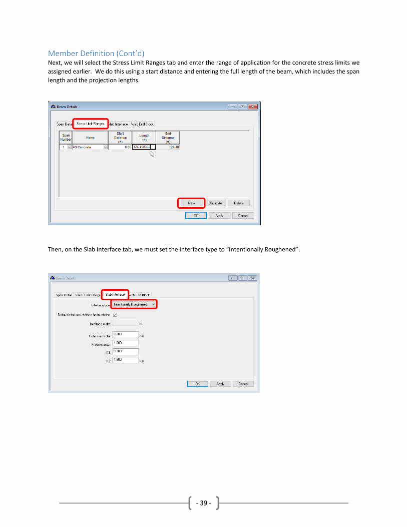
Member Definition (Cont’d) Next, we will select the Stress Limit Ranges tab and enter the range of application for the concrete stress limits we
assigned earlier. We do this using a start distance and entering the full length of the beam, which includes the span
length and the projection lengths.
Then, on the Slab Interface tab, we must set the Interface type to “Intentionally Roughened”.

- 40 -
Mild Steel Layout This window allows you to define the mild steel layout for a prestressed concrete beam span. Mild steel information
can be taken from the plan sheet located on page 6 of this example, as well as the referenced standard drawing.

- 41 -
Strand Layout This window allows you to define a prestress strand layout for a prestressed concrete beam span. In our example,
we have harped strands and beam sections from the ends and mid span. These details can be found on the plan
sheet located on page 6. By looking at the detail presented in the window, you can see the grid locations where
strands can currently be placed. At the top, you can also see the mild steel bars that we previously created. This
window can be a good way to check your locations when entering prestress beam mild steel.

- 42 -
Strand Layout (Cont’d) When a standard beam shape is selected from the library, the grid of available locations for strands to be located
are set by default. In our case, we need to add some additional locations where strands are to be located. To do
this we will go back to the I-Beam Shape window and select the OH-Modified AASHTO TYPE 4 (66).
From here, we will click on the Strand Grid tab and create new additional rows of strands to the existing grid. Add
the rows shown in the figure below and then click ok.
Then, we will navigate back to the Strand Layout window and you can see that additional grid spaces have been
added to the detail.

- 43 -
Strand Layout (Cont’d)
Now that the detail is shown correctly, we can select the harped strand configuration type and click the points to
add our strands to the necessary positions from the plan sheet on page 6.

- 44 -
Strand Layout (Cont’d) Once the strands are shown correctly on the detail, we can then click the “Left end” toggle and enter our harp point
dimensions. After the harp distance has been completed, we can examine the end span detail on page 6 and, once
again, click the locations where the harped strands are located. You will notice that when the locations are selected
they will turn blue and the lower bars from the mid span section will turn gray. This is done so that we can identify
which strands are harped and which bars are straight.
Click the “OK” button when all the stands have been entered correctly and match the figure above.
- 45 -
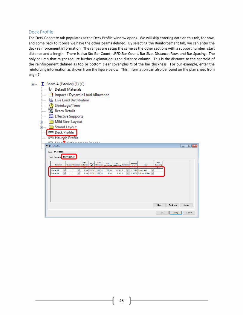
Deck Profile The Deck Concrete tab populates as the Deck Profile window opens. We will skip entering data on this tab, for now,
and come back to it once we have the other beams defined. By selecting the Reinforcement tab, we can enter the
deck reinforcement information. The ranges are setup the same as the other sections with a support number, start
distance and a length. There is also Std Bar Count, LRFD Bar Count, Bar Size, Distance, Row, and Bar Spacing. The
only column that might require further explanation is the distance column. This is the distance to the centroid of
the reinforcement defined as top or bottom clear cover plus ½ of the bar thickness. For our example, enter the
reinforcing information as shown from the figure below. This information can also be found on the plan sheet from
page 7.

- 46 -
Haunch Profile This window allows you to define the shape and dimensions of the haunch. The haunch is described over ranges,
with each range being defined by a support, a start distance, and a length. This gives you the option to enter various
haunch thicknesses depending on the location. For our example, we will use the maximum haunch thickness of 2⅜”
and apply it to the entire length of the exterior beam.
(Warning: Do not use negative numbers to model a block overhang. Even though it graphically looks correct this will
result in an uplift force rather than the expected dead load.)

- 47 -
Shear Reinforcement Ranges This PS Shear Reinforcement Ranges window allows you to describe the vertical shear reinforcement for a
prestressed concrete beam. The shear reinforcement is described over ranges using the Beam Model, with each
range being defined by a span, a start distance, number of spaces and a spacing. Reinforcing information can be
entered in manually or you can utilize the Stirrup Wizard. For our example, you can enter the information shown
in the figure below. (You can also see the included “Bridge Modeling Information” on page 8 for more details on
the input data shown.)

- 48 -
Copying Member Alternatives Once you have created and completed portions of a member alternative, you have the capability to copy and paste
these definitions to other members. By right clicking a member alternative you can select copy.
Then you can navigate to another member alternative and right click the member alternative folder and select paste.
The default name of the newly copied member alternative will be “Copy of” and the name of the alternative copied.
Any time that a member alternative is copied, it is important to save your model immediately after the copy has
been created. If the model is not saved and certain changes are made within the new alternative, the program will
encounter errors when trying save later progress and any revisions or changes made since the copied alternative
was created can be lost. After you have created the new copy of your member alternative, and saved your model,
you can double click and revise the name of the new alternative. Similar to when we created the original member
alternative, you might try to use a naming convention that is similar to your plans and your existing alternative. For
this example, revise your new alternative name to the match the figure shown on the next page.
- 49 -
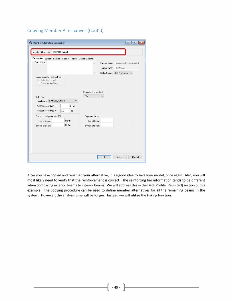
Copying Member Alternatives (Cont’d)
After you have copied and renamed your alternative, it is a good idea to save your model, once again. Also, you will
most likely need to verify that the reinforcement is correct. The reinforcing bar information tends to be different
when comparing exterior beams to interior beams. We will address this in the Deck Profile [Revisited] section of this
example. The copying procedure can be used to define member alternatives for all the remaining beams in the
system. However, the analysis time will be longer. Instead we will utilize the linking function.

- 50 -
Linking Members To reduce analysis time, you can use the “Link with” feature. You can link a member by opening the member (G6)
by double clicking it, and then link with a member you already created (G1) by using the dropdown to select the
appropriate member to link with, see below. You can also link the remainder of the interior beams to G2. Only link
members with identical section properties and beam spacing. If you link say G5 (interior beam) with G1 (exterior
beam) the result will not be valid.
Repeat this process and link the interior members G3, G4, & G5 to G2. You can see when a member is linked with
another when the name of the member is G6 (G1). This shows that G6 is linked with G1 and only G1 will be analyzed.

- 51 -
Deck Profile [Revisited] Once we have created/assigned member alternatives for all the beams in our bridge system, we can revisit the deck
profile for each of the defined members and select the Deck Profile and enter concrete deck dimensions and assign
a material. Instead of calculating and entering this information manually, we can utilize the “Compute from Typical
Section…” button and, if your typical section window has information correctly entered, the deck concrete
information will automatically be calculated and populated.

- 52 -
Deck Profile [Revisited] (Cont’d) This deck profile computation process must be repeated for all other member alternatives that are defined. If a
member is linked to another defined member, then the link source member must have its deck profile defined using
this calculation. For our example, we will only have to perform this process for members G1 and G2.
As we go back and calculate the deck concrete information for G2, this is also a good time to view the Reinforcement
tab for our interior member and review/revise the reinforcing bar information, as previously mentioned. Replace
the default reinforcing bar information (that we previously entered for the exterior member) with the revised
numbers shown in the figure below.
- 53 -
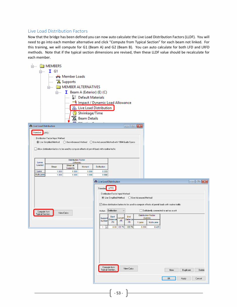
Live Load Distribution Factors Now that the bridge has been defined you can now auto calculate the Live Load Distribution Factors (LLDF). You will
need to go into each member alternative and click “Compute from Typical Section” for each beam not linked. For
this training, we will compute for G1 (Beam A) and G2 (Beam B). You can auto calculate for both LFD and LRFD
methods. Note that if the typical section dimensions are revised, then these LLDF value should be recalculate for
each member.

- 54 -
Model Validation One of the tools you may find useful is Validate. If you select member alternative Beam A an icon in the top will
activate and be avalible to use. When you click Validate this will show you any erros or warnings currently in your
model. You may encounter other errors during analysis but this give a good starting point to debug bridge models.
This validation will also run whenever you save your model.
Validation
Window
Validate Button
Validation
Window

- 55 -
Bridge Alternatives Bridge Alternatives are used to assign Superstructure Definitions so that they can be analyzed from the Bridge
Explorer. This first thing you need to do is create a bridge alternative by double clicking the “Bridge Alternatives”
folder. For this example, you can set a name for the alternative as shown below.
From here, we can create a superstructure for this alternative by double clicking the “SUPERSTRUCTURES” folder. It
is recommended to name this superstructure similar to the superstructure definition that we built earlier and are
planning on analyzing.
- 56 -
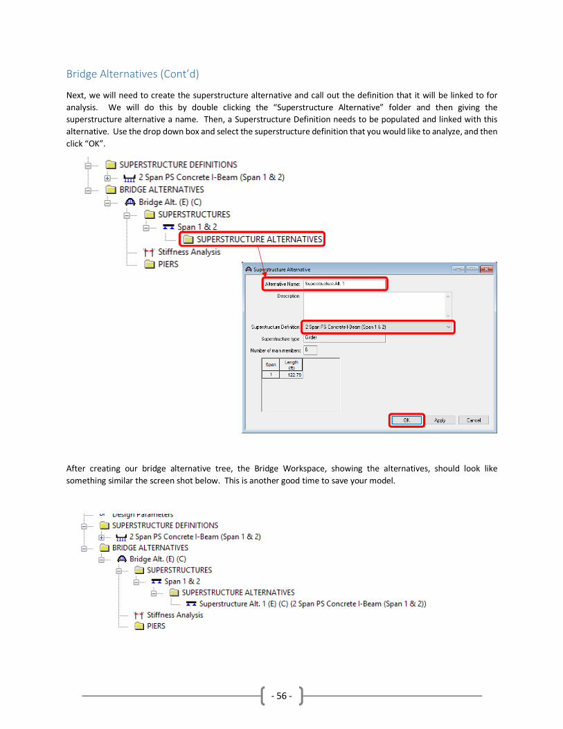
Bridge Alternatives (Cont’d)
Next, we will need to create the superstructure alternative and call out the definition that it will be linked to for
analysis. We will do this by double clicking the “Superstructure Alternative” folder and then giving the
superstructure alternative a name. Then, a Superstructure Definition needs to be populated and linked with this
alternative. Use the drop down box and select the superstructure definition that you would like to analyze, and then
click “OK”.
After creating our bridge alternative tree, the Bridge Workspace, showing the alternatives, should look like
something similar the screen shot below. This is another good time to save your model.

- 57 -
RUNNING ANALYSIS To run the analysis right click on the bridge you just created and select Rate.

- 58 -
Running Analysis (Cont’d)
The Analysis Settings window will open and display the current Rating Method, Analysis Type, Vehicle Selection, and
Vehicle Summary. You can access preset templates by clicking the “Open Template” button. You may have some
templates that are automatically included with your installation of the software. You can manually add vehicles
from the Vehicle Selection side to the Vehicle Summary Side. In the Vehicle Selection are all of the available vehicles
populated from your library that can be selected and analyzed. The Vehicle Summary window shows the vehicles
that you currently have selected for your analysis.
To add vehicles to the summary list, simple click the specific folder you would like to add a vehicle to on the vehicle
summary and then click the vehicle on the selection list and then click the “Add to Rating” button. You can repeat
this process multiple times and add multiple vehicles to the Vehicle Summary list to be analyzed. Once you have
your vehicle list set, you can also click the “Save Template” button and these vehicles listed and the analysis settings
can quickly be populated and repeated in the future. For this example, we will include all of the standard vehicles
required by the BDM to perform an Ohio Legal Load Rating for LFD Line Girder Analysis.
• Note: If you have any non-standard vehicles defined, they can also be added using this same
process. For example, if you were to analyze a permit issued vehicle, you could simply define the
vehicle in the library and then select it for analysis from this window.

- 59 -
Running Analysis (Cont’d)
Once you have selected all of your vehicles to the summary list, simply click “OK to begin your analysis.

- 60 -
Running Analysis (Cont’d)
When the analysis is complete click OK and the results will appear. These are your controlling load ratings for each
vehicle. You can see ratings for each girder by selecting the vehicle of interest and clicking “View Structure Rating
Results”

- 61 -
Running Analysis (Cont’d)
The analysis can also be run within the bridge workspace. By running the analysis from the Bridge Workspace you
can access more specific details about the analysis. Prior to running the analysis, you must again set the Analysis
Settings just as we did when we ran the analysis from the Explorer Window. By running the analysis from within the
bridge workspace, you can find details about the location and mode of the critical rating factor. You can also view
the spec check results of each individual beams line.
Run Analysis
Analysis Settings
Run Analysis
View Spec Check
Controlling Ratings
Controlling Locations

- 62 -
MODELING DETERIORATION As bridge owners know, our structure conditions do not remain the same throughout time. All
structures encounter deterioration in some form or another. The condition state of a bridge that has
just been built can change juristically over time, and when we calculate the load rating values, we must
ensure that we incorporate deterioration in our bridge models. In terms of this prestress structure, we
will account for loss of capacity by modeling the loss of prestress strands in spalled areas of the concrete
beams.
Removing Deteriorated Prestressed Strands
As a result of a recent inspection, a number of prestressed strands were found exposed from a concrete
spall located on interior “Beam C”. A total of 3 strands in the bottom row are visible from below the
beam. As a rule of thumb, ODOT load raters typically consider exposed strands lost in terms of taking
capacity, as well as the immediate neighboring strands. Choosing which strands are going to be utilized
and which strands are to be eliminated due to corrosion is an engineering judgement decision.
Visually Exposed
Strands to be removed
Neighboring Strands to
be removed

- 63 -
Unlinking/Copying Member Alternatives
We first need to unlink the interior member so that it can be modeled separately from the other internal
members. To do this, we will simply double click the member we wish to unlink and select “None” in
the Link with selection drop down.
Next, we will copy the member from G2 and paste it in the Member Alternatives for G3. Both G2 and G3
are interior girders, so the only difference between members will be strands that we remove to account
for deterioration.

- 64 -
Unlinking/Copying Member Alternatives (Cont’d)
As a reminder, anytime you copy and paste definitions in a model, be sure to save your progress routinely.
This is one of the most common instances where models encounter errors. Once we have pasted the
interior beam definition into G3, we can rename it so that the naming convention is consistent with the
rest of the model. By double clicking the member alternative, the description window will populate. This
is where you can revise the member name, and when modeling a member for deterioration, it is a good
idea to state that the beam has deterioration in the Description Text Box, as shown below.
Once again, after the name has been revised, be sure to save the model.
- 65 -
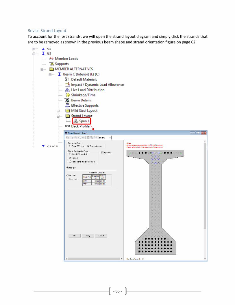
Revise Strand Layout
To account for the lost strands, we will open the strand layout diagram and simply click the strands that
are to be removed as shown in the previous beam shape and strand orientation figure on page 62.

- 66 -
Unlinking/Copying Member Alternatives (Cont’d)
After the strands have been removed, click OK and then the model is ready for analysis. (Refer to page
58 for how to run analysis and view results.) Upon looking at the results, you can see the difference that
the missing strands make when comparing the capacities from various vehicles for interior beams B & C.

- 67 -
APPENDIX Ohio DOT Structures – Bridge Management Section
http://www.dot.state.oh.us/Divisions/Engineering/Structures/BridgeManagementSection/Pages/default
.aspx
Description Conventions
http://www.dot.state.oh.us/Divisions/Engineering/Structures/BridgeManagementSection/Documents/B
rR_Description_Conventions_2017-05-12.docx