h haunch- see table di
TRANSCRIPT

Di
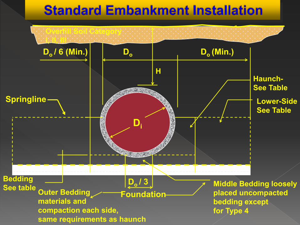
Bedding See table
Do / 3 Foundation Outer Bedding
materials and compaction each side, same requirements as haunch
Middle Bedding loosely placed uncompacted bedding except for Type 4
Haunch- See Table
Lower-Side See Table
Overfill Soil Category I, II, III
Do / 6 (Min.) Do Do (Min.)
H
Springline

209.04 - “Borrow Type C (Backfill). This material shall have between 85 and 100% inclusive by dry weight, passing a 1” (25 mm) sieve and a maximum of 25% by dry weight, passing a No. 200 (75 μm) sieve.

208.04 “For these areas, (below the roadway or
shoulders) backfill material shall be compacted to 95% or more of maximum density according to the requirements of subsection 202.05 (f).”
“For these areas, (locations other than the below the roadway and shoulders) backfill material shall be compacted to 90% or more of the maximum density according to the requirements of subsection 202.05 (f).”

Standard Installations › Developed by ASCE (15-93) › Adopted by AASHTO (Sections
16 & 27) › LRFD Section 12 and Section 27
of Construction Standard


DC Power Supply Data Acquisition Sys

Soil Pipe Interaction Design & Analysis

INCREASED PIPE DESIGN
PIPE
STRENGTH INSTALLATION
QUALITY
INCREASED MATERIAL QUALITY
2 1 3 4
INSTALLATION TYPE


1.5
1.0 0.5
0.0
0.5 0.0
1.0 1.5 2.0 2.5
3.0
3.5 4.0
4.5
0.0 0.5 1.0 1.5 0.0 0.5 1.0 1.5

1.5
1.0 0.5
0.0
0.5 0.0
1.0 1.5 2.0 2.5
3.0
3.5 4.0
4.5
0.0 0.5 1.0 1.5 0.0 0.5 1.0 1.5

We = prism load x VAF Where : VAF = vertical arching factor as per Heger distribution
Prism Load Area
Final Grade
O.D.

Installation Type
VAF HAF
1 1.35 0.45 2 1.40 0.40 3 1.40 0.37 4 1.45 0.30
ARCHING FACTORS

Vertical Pressures

WE = FeγsBcH › Pipe – Section 12.10.2.1-1


TRENCH
Vertical Pressures

“Standard installations for both embankments and trenches shall be designed for positive projection, embankment loading conditions where Fe shall be taken as the vertical arching factor, VAF, specified in Table 12.10.2.1-3 for each type of standard installation.”
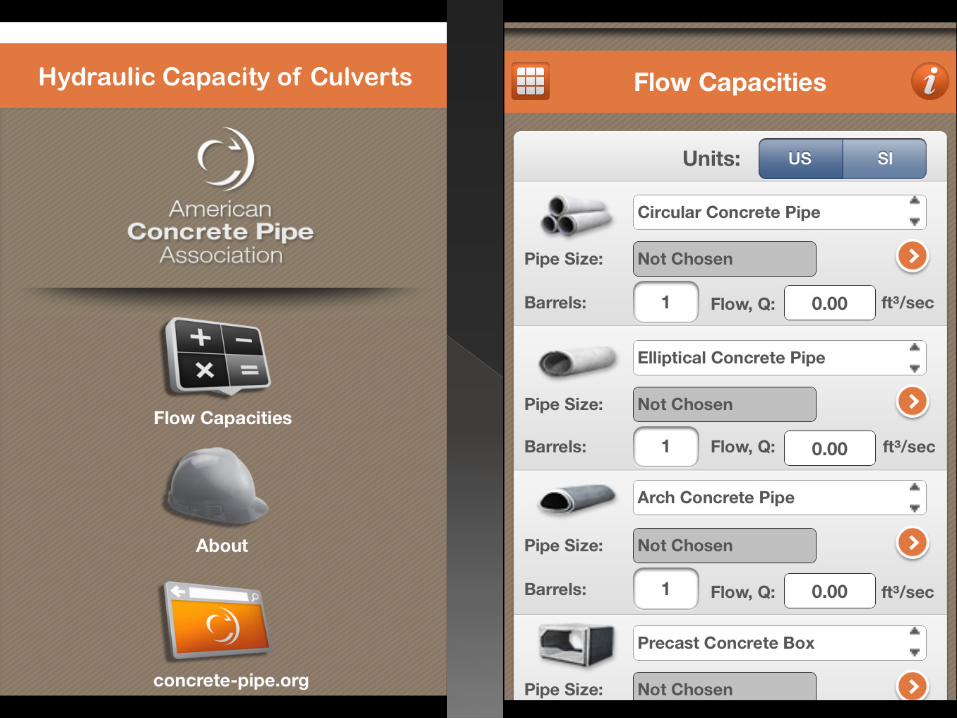
www.concrete-pipe.org

www.concrete-pipe.org
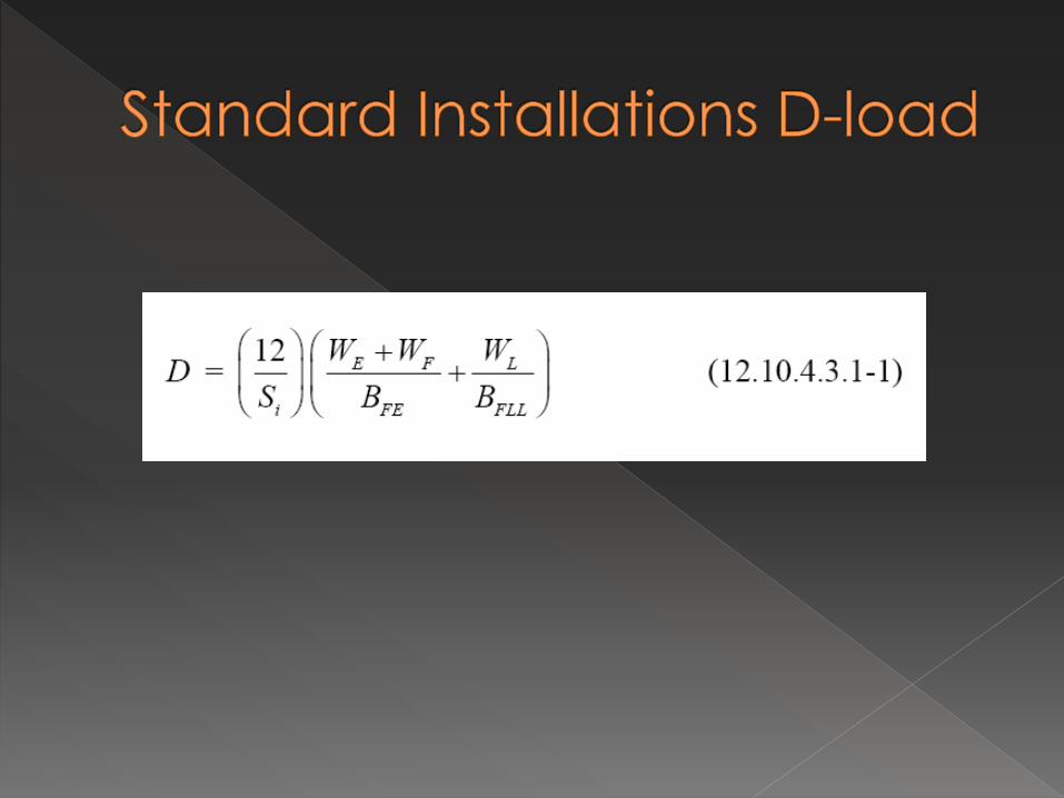
Concrete Pipe Indirect Design – 12.10.4.3 D-Load Equation


Di
Bedding See table
Do / 3 Foundation Outer Bedding
materials and compaction each side, same requirements as haunch
Middle Bedding loosely placed uncompacted bedding except for Type 4
Haunch- See Table
Lower-Side See Table
Overfill Soil Category I, II, III
Do / 6 (Min.) Do Do (Min.)
H
Springline
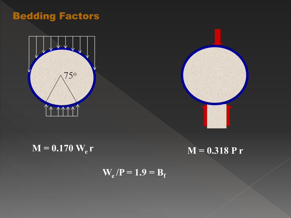
Bedding Factors
M = 0.170 We r M = 0.318 P r
We /P = 1.9 = Bf
75o

D-Load
Supporting strength of a pipe loaded under three-edge bearing test conditions, expressed in pounds per linear foot per foot of inside diameter or horizontal span.
ASTM C-76 Class IV
D0.01 = 2000
DULT = 3000


Bedding Factors
Bf = ?

Embankment Earth Load Bedding Factor

www.concrete-pipe.org
Extra Safety Factor for Type 1 Installations


E = 96 + 1.44S (4.6.2.10.2-1) E = Distribution width perpendicular to span in inches S = Clear Span in feet
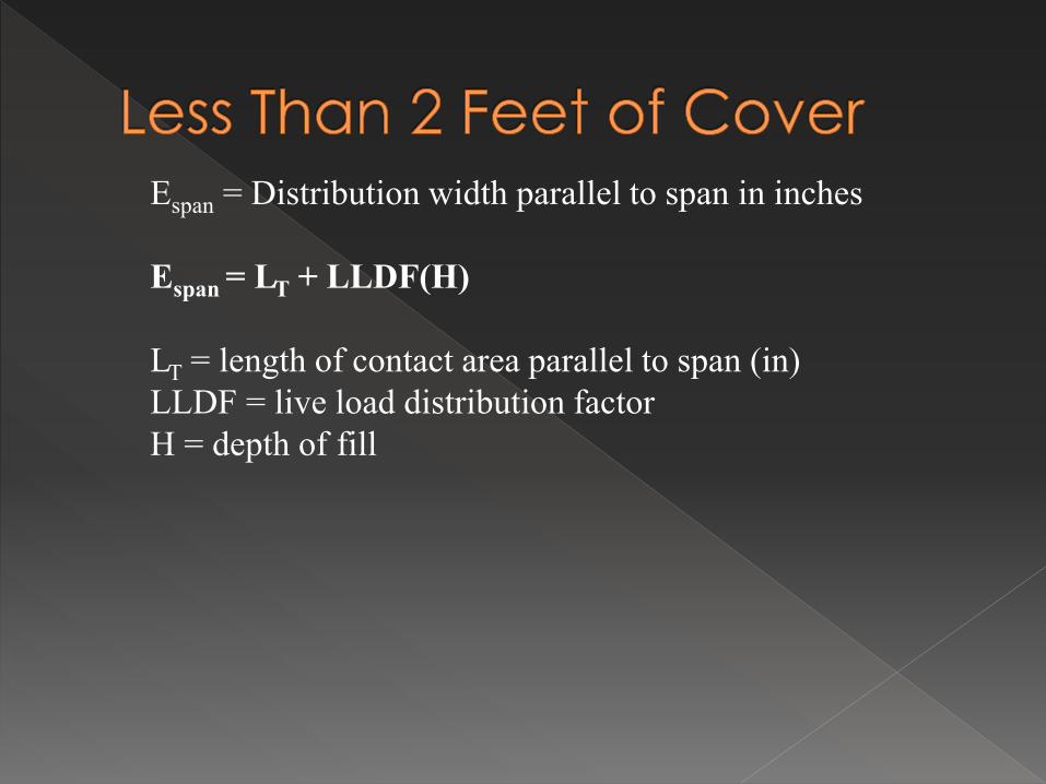
Espan = Distribution width parallel to span in inches Espan = LT + LLDF(H) LT = length of contact area parallel to span (in) LLDF = live load distribution factor H = depth of fill
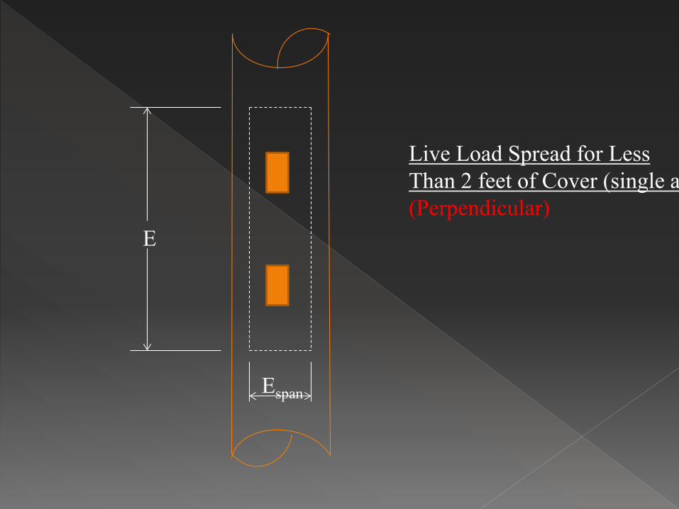
E
Live Load Spread for Less Than 2 feet of Cover (single a (Perpendicular)
Espan

E = 96 + 1.44S (4.6.2.10.2-1) E = Distribution width perpendicular to span in inches S = Clear Span in feet Note: Equation 4.6.2.10.2-1 is for an axle load. with pipe, having much smaller spans than boxes a distribution for wheel loads is more appropriate. Ewheel = 48 + 0.72S

E
Live Load Spread for Less Than 2 feet of Cover (Parallel)
E2
WE

E
Live Load Spread for Less Than 2 feet of Cover (single axle (Perpendicular)
Espan
Espan = lt + LLDF(H) (4.6.2.10.2-2)

E
Live Load Spread for Less Than 2 feet of Cover (single axle (Perpendicular)
Espan
ALL = lw ww (3.6.1.2.6a-1) ALL = Espan * E ALL = rectangular area at depth H (ft2) lw = live load patch length at depth H (ft) ww = live load patch width at depth h (ft)

wt = 20 in.
lt = 10 in. Tire Patch
Direction of Traffic Article 3.6.1.2.5


sw = wheel spacing, 6.0 ft. sa = axle spacing (ft)

Hintd
Elevation View
sa
Interaction Depth for Tandem Axles (Perpendicular)
Plan View
lws when H<Hintd
lwt when H>Hintd lws when H>Hintd
sa
lws
lwt
PRdist < 0
Hintw
Elevation View
Plan View
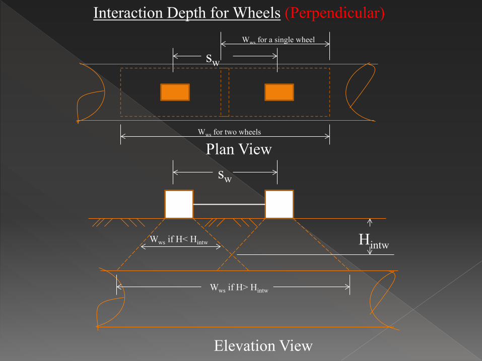
sw
Interaction Depth for Wheels (Perpendicular)
Wws if H< Hintw
Wws if H> Hintw
sw
Wws for a single wheel
Wws for two wheels

sw = wheel spacing, 6.0 ft wt = tire patch width, 20 in. Di = inside diameter or clear span of the culvert (in)

Where H < Hint-t
Ww = wt/12 + LLDF(H) + 0.06(Di/12) (3.6.1.2.6b-2)
Where H > Hint-t
Ww = wt/12 + sw + LLDF(H) + 0.06(Di/12) (3.6.1.2.6b-3)

“For live load distribution parallel to culvert span, the wheel/axle load Interaction depth Hint-p shall be determined as:”
Hint-p = sa -
lt
12
LLDF
sa = axle spacing (ft) lt = tire patch length, 10 (in) LLDF = live load distribution factor
(3.6.1.2.6b-4)

Where H < Hint-p
lw = lt/12 + LLDF(H) (3.6.1.2.6b-5)
Where H > Hint-p
lw = lt/12 + sa + LLDF(H) (3.6.1.2.6b-6)

Pressure Area at the Top of the Pipe
ww
lw
Plan View
ww
lw
ALL = lw ww (3.6.1.2.6a-1)

1 + IM 100 ( ) P (m)
ALL
PL = (3.6.1.2.6b-7)
PL = live load vertical crown pressure (ksf) P = live load applied at surface on all interacting wheels (kips) IM = dynamic load allowance as specified in Article 3.6.2.2 m = multiple presence factor specified in Article 3.6.1.1.2

LRFD – Dynamic Load Allowance (3.6.2.2) › DLA = 0.33(1.0 - 0.125DE) DE = Depth of cover (ft)

Design Code
Lanes AASHTO STD
AASHTO LRFD
1 1.0 1.2
2 1.0 1.0
3 0.90 0.85
4 0.75 0.65

For Concrete Pipe, Load must be in Terms of lbs/ft
Do
1 ft.
L = Smaller of lw or Do
WL = PL * L = live load (lbs/ft)
lw

12 Si
( ) ( WE + WF
BFE +
WL
BFLL ) D = (12.10.4.3.1-1)
BFLL = Live Load Bedding Factor

Pipe Diameter, in
Fill Height, ft < 2 ft > 2 ft
12 3.2 2.4 18 3.2 2.4 24 3.2 2.4
30 and larger 2.2 2.2
Table 12.10.4.3.2c-1


Embankment Condition › Pipe Size = 36” I.D., 44” = 3.67 ft. - Do › Fill Height = H = 5 ft. › Soil Unit Weight = w = 120 lbs/ft3
› Check Type 2 and Type 3 Installations

1. Determine Earth Load 2. Determine Live Load 3. Select Bedding 4. Determine Bedding Factor 5. Application of Factor of Safety 6. Selection of Pipe Strength

Soil Prism Load: › PL = w H Do › PL = (120 lbs/ft3)(5 ft.)(3.67 ft.) › PL = 2202 lbs/ft › W = VAF x PL (AASHTO Equation 12.10.2.1-1) › Type 2 Type 3 › W = (1.40)(2202 lbs/ft) W = (1.40)(2202 lbs/ft) › W = 3083 lbs/ft W = 3083 lbs/ft


γw = 62.4 pcf ID = 3 ft Wf = γw x π x (ID/2)2
Wf = 441 lbs/ft

3.6.1.2.6a › “For single-span culverts, the effects of live
load may be neglected where the depth of fill is more than 8.0 ft. and exceeds the span length;”


LLDF = 1.15 + (3 ft – 2 ft) (8 ft – 2 ft)
(1.75 – 1.15)
LLDF = 1.25

Hint-t = 6 ft. – (20”/12) – (0.06 * 36”)/12
1.25
Hint-t = 3.32 ft

Hintw
Elevation View
Plan View
sw
Interaction Depth for Wheels (Perpendicular)
Wws if H< Hintw
Wws if H> Hintw
sw
Wws for a single wheel
Wws for two wheels

“For live load distribution parallel to culvert span, the wheel/axle load Interaction depth Hint-p shall be determined as:”
Hint-p = sa -
lt
12
LLDF
Hint-p =
(3.6.1.2.6b-4)
4 ft – (10”/12) 1.25
Hint-p = 2.53 ft

Hintd
Elevation View
sa
Interaction Depth for Tandem Axles (Perpendicular)
Plan View
lws when H<Hintd
lwt when H>Hintd lws when H>Hintd
sa
lws
lwt
PRdist < 0

For The Single Axle (HS20)
Where H > Hint-t
Ww = wt/12 + sw + LLDF(H) + 0.06(Di/12) (3.6.1.2.6b-3)
Ww = (20”/12) + 6 ft + 1.25*5 ft + 0.06*3 ft
Ww = 14.1 ft
Where H < Hint-p
lw = lt/12 + LLDF(H) (3.6.1.2.6b-5)
lw = 10”/12 + 1.25*5 ft. lw = 7.1 ft
ALL = 14.1 ft x 7.1 ft = 100 ft2

For The Tandem Axles
Where H > Hint-t
Ww = wt/12 + sw + LLDF(H) + 0.06(Di/12) (3.6.1.2.6b-3)
Ww = (20”/12) + 6 ft + 1.25*5 ft + 0.06*3 ft
Ww = 14.1 ft
Where H > Hint-p
lw = lt/12 + sa + LLDF(H) (3.6.1.2.6b-5)
lw = 10”/12 + 4 ft + 1.25*5 ft. lw = 11.1 ft
ALL = 14.1 ft x 11.1 ft = 156.5 ft2

1 + IM 100 ( ) P (m)
ALL
PL = (3.6.1.2.6b-7)
Load P For the single axle – P = 16 kips x 2 wheel loads P = 32 kips For the tandem axle – P = 12.5 kips x 4 wheel loads P = 50 kips

1 + IM 100 ( ) P (m)
ALL
PL = (3.6.1.2.6b-7)
IM = 33*[1 – 0.125 (H)] IM = 33*[1 – 0.125 (5)] IM = 12.375 m = 1.2 for a single lane

1 + IM 100 ( ) P (m)
ALL
PL = (3.6.1.2.6b-7)
1 + 12.375
100 ( ) 32000 lbs (1.2)
100 ft2 PLs =
1 + 12.375
100 ( ) 50000 lbs (1.2)
156.5 ft2 PLt =
= 431.5 psf
= 430.8 psf

Outside Diameter = 3.67 lbs/ft Spread length for Single Axle
› lw = 7.1 ft Spread length for Tandem Axles
› lw = 11.1 ft
Live load = O.D. x PL › WL = 3.67 ft x 431.5 psf = 1583.6 lbs/ft

For Concrete Pipe, Load must be in Terms of lbs/ft
Do
1 ft.
L = Smaller of lw or Do
WL = PL * L = live load (lbs/ft)
lw

Type 2 › WE = 3083 lbs/ft › WF = 441 lbs/ft › WL = 1583.6 lbs/ft
Type 3 › WE = 3083 lbs/ft › WF = 441 lbs/ft › WL = 1583.6 lbs/ft

We will compare Type 2 and Type 3 installations.


Earth Load Bedding Factors for Embankment Condition (Table 12.10.4.3.2a-1) › Type 2, BFE = 2.9 › Type 3, BFE = 2.3

Pipe Diameter, in
Fill Height, ft < 2 ft > 2 ft
12 3.2 2.4 18 3.2 2.4 24 3.2 2.4
30 and larger 2.2 2.2
Table 12.10.4.3.2c-1
Type 2, BFLL = 2.2 Type 3, BFLL = 2.2

Find D-load
Design is based on 0.01 inch crack, so use a factor of safety of 1.0.

D0.01 = 3,083 lbs/ft + 441 lbs/ft 2.9
1584 lbs/ft x 1.0 3 ft
D0.01 = 645 lbs/linear ft/ft of diameter
+ 2.2
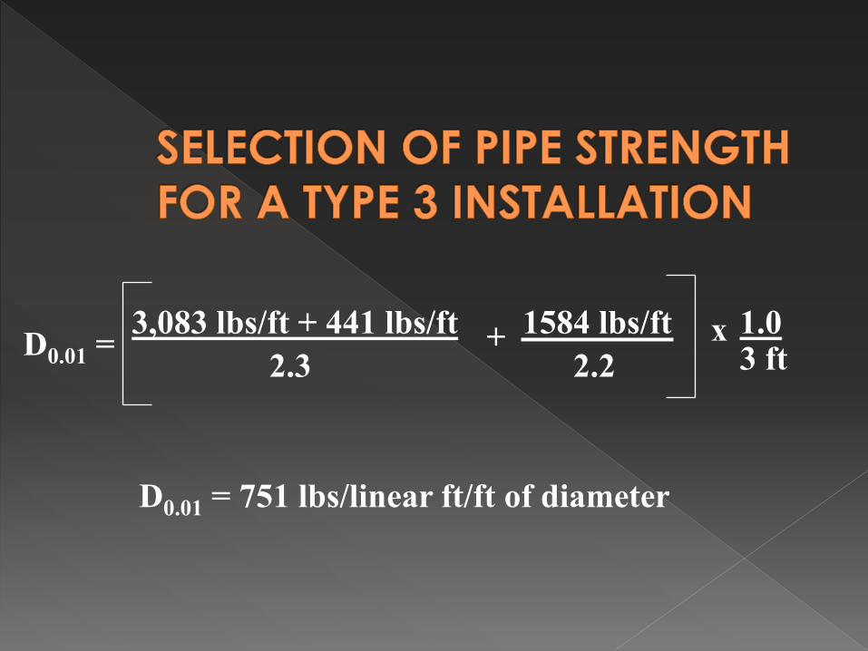
D0.01 = 3,083 lbs/ft + 441 lbs/ft 2.3
1584 lbs/ft x 1.0 3 ft
D0.01 = 751 lbs/linear ft/ft of diameter
+ 2.2

Class I - D0.01 = 800 lbs/ft/ft Class II - D0.01 = 1000 lbs/ft/ft Class III - D0.01 = 1350 lbs/ft/ft Class IV - D0.01 = 2000 lbs/ft/ft Class V - D0.01 = 3000 lbs/ft/ft


Find D-load

WE = FeγsBcH › Pipe – Section 12.10.2.1-1


Not the Same Earth Load Bedding Factor As Circular Pipe


Bedding Factor Per AASHTO

Fe = 1.4

Bedding Factor Per AASHTO

Pipe Diameter, in
Fill Height, ft < 2 ft > 2 ft
12 3.2 2.4 18 3.2 2.4 24 3.2 2.4
30 and larger 2.2 2.2
Table 12.10.4.3.2c-1

34 x 53 horizontal elliptical pipe Positive projecting embankment
condition Type 2 Installation 1 foot of cover Soil unit weight of 120 lbs/ft3

1. Determine Earth Load 2. Determine Live Load 3. Select Bedding 4. Determine Bedding Factor 5. Application of Factor of Safety 6. Selection of Pipe Strength

Wall thickness = 5 in. (from ASTM C 507) Outside Span Bc = 53 in + 2 (5 in.) = 5.25 ft Soil Prism Load:
› PL = w H Bc › PL = (120 lbs/ft3)(1ft.)(5.25 ft.) › PL = 630 lbs/ft › W = VAF x PL (AASHTO Equation 12.10.2.1-1) › Type 2 › W = (1.40)(630 lbs/ft) › W = 882 lbs/ft

γw = 62.4 pcf A = 10.2 ft Wf = γw x A
Wf = 636 lbs/ft


Espan = Distribution width parallel to span in inches Espan = LT + LLDF(H) LT = length of contact area parallel to span (in) LLDF = live load distribution factor H = depth of fill

E = 96 + 1.44S (4.6.2.10.2-1) E = Distribution width perpendicular to span in inches S = Clear Span in feet

Espan = Distribution width parallel to span in inches Espan = LT + LLDF(H) LT = length of contact area parallel to span (in) LLDF = live load distribution factor H = depth of fill

E
Live Load Spread for Less Than 2 feet of Cover (single a (Perpendicular)
Espan

E = 96 + 1.44 (53”/12) E = 102.36 inches = 8.53 ft.
LLDF = 1.39 E = 10”/12 + 1 ft x 1.39 E = 2.22 ft.

ALL = E * Espan ALL = 8.53 ft x 2.22 ft ALL = 18.94 ft2
P = 32,000 lbs
M = 1.2

1 + IM 100 ( ) P (m)
ALL
PL = (3.6.1.2.6b-7)
IM = 33*[1 – 0.125 (H)] IM = 33*[1 – 0.125 (1)] IM = 28.88

1 + IM 100 ( ) P (m)
ALL
PL = (3.6.1.2.6b-7)
1 +
28.88 100 ( ) 32000 lbs (1.2)
18.94 ft2 PL =
PL = 2,613 psf

OD = 5.25 ft. Espan = 2.22 ft Espan < OD, so use Espan for live load
calculation
WLL = 2.22 ft x 2613 psf WLL = 5,801 lbs/ft

Type 2 › WE = 882 lbs/ft › WF = 636 lbs/ft › WL = 5801 lbs/ft


Bedding Factor Per AASHTO

Fe = 1.4 p = 0.7 Bc = 5.25 ft. H = 1 ft. q= 0.263

BFE = CA
CN - xq
CA = 1.337 CN = 0.630 x = 0.369 q = 0.263
BFE = 1.337
0.630 – 0.369*0.263
BFE = 2.5

Pipe Diameter, in
Fill Height, ft < 2 ft > 2 ft
12 3.2 2.4 18 3.2 2.4 24 3.2 2.4
30 and larger 2.2 2.2
Table 12.10.4.3.2c-1
BFLL = 2.2

Find D-load

Design is based on 0.01 inch crack, so use a factor of safety of 1.0.

D0.01 = 882 lbs/ft + 636 lbs/ft 2.5
5801 lbs/ft x 12 53 in.
D0.01 = 735 lbs/linear ft/ft of diameter
+ 2.2

Class HE-A - 600 lbs/ft/ft Class HE-1 - 800 lbs/ft/ft Class HE-II - 1000 lbs/ft/ft Class HE-III - 1350 lbs/ft/ft Class HE-IV - 2000 lbs/ft/ft

25 kips 25 kips 4 ft
