aashto abc guide specifications, seismic design ... · aashto abc guide specifications, seismic...
TRANSCRIPT

Module 2 –
AASHTO ABC Guide Specifications, Seismic Design Requirements for Connections
Lee Marsh, Ph.D., P.E
Deputy Director – America’s Technical Excellence Center
Greg Banks, P.E., S.E
Project Manager and Senior Bridge Engineer

AASHTO LRFD Guide Specifications for ABC
AASHTO Guide Specifications for ABC
NCHRP 12-102 Final Report provides
additional commentary and background
2

Outline
I. Overview of AASHTO LRFD Guide Specifications for ABC- Seismic
II. Seismic Design for ABC (3.4)
III. Seismic Connection Design and Detailing (3.6.4-7 & 3.4.12)
Overview Seismic Design Connections 3

I. Overview of Guide Specifications for ABC- Seismic
• Aims to ensure minimal damage of the structure under moderate earthquake and collapse prevention under rare earthquakes.
• Adopts a Type I design strategy exclusively (inelastic behavior under ductile limit state should occur only in the substructure).
• Written to supplement (not to replace) the current specifications.
• Future editions of Guide Specifications for ABC are expected to incorporate ongoing ABC seismic research.
Overview Seismic Design Connections 4

II. Seismic Design for ABC (3.4)
• Force-Based Design
(AASHTO LRFD, 2017)
OR
• Displacement-Based Design
(AASHTO SGS, 2011)
Regardless of the seismic analysis/design method the Earthquake Resisting Systems (ERS) and Elements (ERE) shall be identified.
Overview Seismic Design Connections 5

II. Seismic Design for ABC
Ductile LinkBrittle Links Brittle Links
Force, F F
FdFib
Ductile Behavior, Fd < All Fib
Brittle Behavior, Any Fib < Fd
Displacement, ∆
F
Overview Seismic Design Connections 6
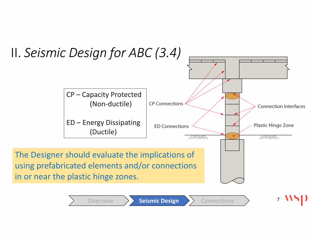
The Designer should evaluate the implications of
using prefabricated elements and/or connections
in or near the plastic hinge zones.
CP – Capacity Protected
(Non-ductile)
ED – Energy Dissipating
(Ductile)
II. Seismic Design for ABC (3.4)
Overview Seismic Design Connections 7

II. Seismic Design for ABC (3.4)
All members of the ERS
must have sufficient
strength and ductility to
form the intended
structural plastic
mechanism.
Overview Seismic Design Connections 8

II. Seismic Design for ABC (3.4)
• Ensure continuity of load path under load reversals.
• Ensure development of cyclic inelastic deformations.
• Realize that maximum demands typically occur at connections of
prefabricated elements.
• Limit the occurrence of conditions leading to rapid loss of
resistance (local buckling, stress concentrations, etc.)
DETAILING IS IMPORTANT!
Overview Seismic Design Connections 9

II. Seismic Design for ABC
All connections and Earthquake Resisting Elements
(EREs) in the GS for ABC only permitted with the
Owner’s approval.
Overview Seismic Design Connections 10

III. Seismic Connection Design and Detailing (3.6)
Other details are permitted provided that:
1. They are approved by the Owner,
AND
2. The designer demonstrates adequate load transfer with consideration for compatibility of deformations and constitutive relations of materials.
11Overview Seismic Design Connections
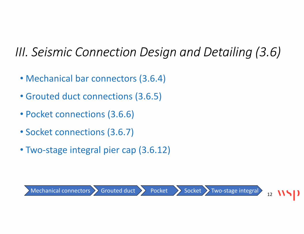
III. Seismic Connection Design and Detailing (3.6)
• Mechanical bar connectors (3.6.4)
• Grouted duct connections (3.6.5)
• Pocket connections (3.6.6)
• Socket connections (3.6.7)
• Two-stage integral pier cap (3.6.12)
Mechanical connectors Grouted duct Pocket Socket Two-stage integral12

Source: Haber et al.,(2013)
Headed Bar
Coupler (HC)
PC Column
Footing
3.6.4 Mechanical Bar Connectors
Grouted Sleeve
Coupler
PC Column
Note: No more than one connector per bar in
plastic hinge zone is allowed (3.6.4.4) so this
detail does not meet the GS for ABC.
(GC)
Mechanical connectors Grouted duct Pocket Socket Two-stage integral 13

• Connector Types as defined in ACI 318-14
• Type 1: Capacity ≥(1.25 fy )Ab
• Type 2: Capacity ≥(fu )Ab
3.6.4 Mechanical Bar Connectors
fy
fu
Connector
Stress
Strain
Bar Bar
(Limited to bars with fy≤60 ksi)
Ab
Mechanical connectors Grouted duct Pocket Socket Two-stage integral 14

3.6.4 Mechanical Bar Connectors
Column
Dc
2Dc
Type 1 connector: not allowed
Mechanical connectors Grouted duct Pocket Socket Two-stage integral 15

3.6.4 Mechanical Bar Connectors
Plastic
hinge
zone
(PHZ)
Type 2: Allowed
• For SDC A/Seismic Zone 1.
• Seismic SDC B/Zone 2 with
Owner’s approval.
• Seismic SDCs C&D/Zones 3&4
w/ add’l requirements
(3.6.4.4).Column
Mechanical connectors Grouted duct Pocket Socket Two-stage integral 16

Type 2 Connectors in Plastic Hinge Zone for SDCs C&D Seismic Zones 3&4 (3.6.4.4)
Only grouted sleeve coupler
(GC) or headed reinforcement
coupler (HC) allowed.
PHZ<15db
db
Column
Mechanical connectors Grouted duct Pocket Socket Two-stage integral 17

• 0.8 for Lsp ≤ 4 db
• 0.5 for Lsp > 4 db
Type 2 Connectors in Plastic Hinge Zone for Seismic Zones 3&4 (Force-based Design)
• Reduced modification factor ��PHZ
Lsp
Mechanical connectors Grouted duct Pocket Socket Two-stage integral 18
[AASHTO ABC EQ. 3.6.4.4.1-1]

Type 2 Connectors in Plastic Hinge Zone for Seismic Zones 3&4 (Displacement-based Design)
• Use plastic moment capacity based on moment-curvature
analysis of the column section with no mechanical
connector.
• Calculate displacement capacity based on a reduced plastic
hinge length, . ����
Mechanical connectors Grouted duct Pocket Socket Two-stage integral 19

Type 2 Connectors in Plastic Hinge Zone for Seismic Zones 3&4 (Displacement-based Design)
L
Rigid FoundationHsp
LspMechanical
Couplers
ACTUAL CURVATURE
DIAGRAM
����
“EQUIVALENT”
CURVATURE DIAGRAM
Point of
Contraflexure
���� = �� − 1 − ��� ��� ≤ ��
= 0.65 for GC
= 0.75 for HC
Mechanical connectors Grouted duct Pocket Socket Two-stage integral 20
[AASHTO ABC EQ. 3.6.4.4.2-1]

Type 2 Connectors in Plastic Hinge Zone for Seismic Zones 3&4 (Displacement-based Design)
L
If <0.5Dc
If >4db
Point of
Contraflexure
z= Hsp+ Lsp
� = ���(� − �)
�
���
Mechanical connectors Grouted duct Pocket Socket Two-stage integral
Hsp
Lsp
AND
21

Debonding of Longitudinal Reinforcement for Mechanical Connectors in PHZ (3.6.4.5)
ld
����
���� ≥ max 0.4 $% 5000 Ɛye dbl
To be used
for joint
shear design≥
Mechanical connectors Grouted duct Pocket Socket Two-stage integral 22
[AASHTO ABC EQ. 3.6.4.5-1]

3.6.5 GROUTED DUCT CONNECTIONS
Source: Brenes (2006)
ASTM A 760
(only)
≥ 0.67/�012�1′45
(grade 60 bars)
1′4 to be taken≤ 8.0 ksi
3 78 6/�0
Mechanical connectors Grouted duct Pocket Socket Two-stage integral 23
[EQ. 3.6.5.1-1]

3.6.5 GROUTED DUCT CONNECTIONS
UHPC Grouted Duct
Column
PC Pier Cap
UHPC
Grouted Duct
Debonding
≥4db
db
(#8-#11)
fy≤75 ksi
≥4db
≥8db
Mechanical connectors Grouted duct Pocket Socket Two-stage integral 24

3.6.6 POCKET CONNECTIONS
ASTM A 760
(only)
A A
SECTION A-A
(grade 60 bars)
≥ /�012�1′%�5
≥1.5 max agg.
≤ 4 in.
Source: Restrepo et al. (2011)
Mechanical connectors Grouted duct Pocket Socket Two-stage integral 25
[EQ.3.6.6.3-1]

3.6.6 POCKET CONNECTIONSSteel Pipe Thickness 9=9� cos(=)
7�>�� = m?@( ABC�D EFGHEF�IJ�KL , 0.060 in)
Set:
Solve:
•M.NN EC�D5
EFGfor SDCs B and Zone 2
• Max ( M.NN EC�D5 EFG , 0.40 PQR (0SC)T ) For Zones 3 & 4
• Calculated min. joint shear reinf. for SDCs C & D
U� =
Fp
α
D’cp
FH
D’cp
(b) Corrugated
Steel Pipe(a) Spiral
s
Mechanical connectors Grouted duct Pocket Socket Two-stage integral 26
[AASHTO ABC EQ. 3.6.6.4-2]

3.6.7 SOCKET CONNECTIONS
Wet (cast-in-place) Formed (precast)
Embedded
PC Column
Grout or
Concrete Pour
PC CapEmbedded
PC ColumnCIP Footing
Mechanical connectors Grouted duct Pocket Socket Two-stage integral 27
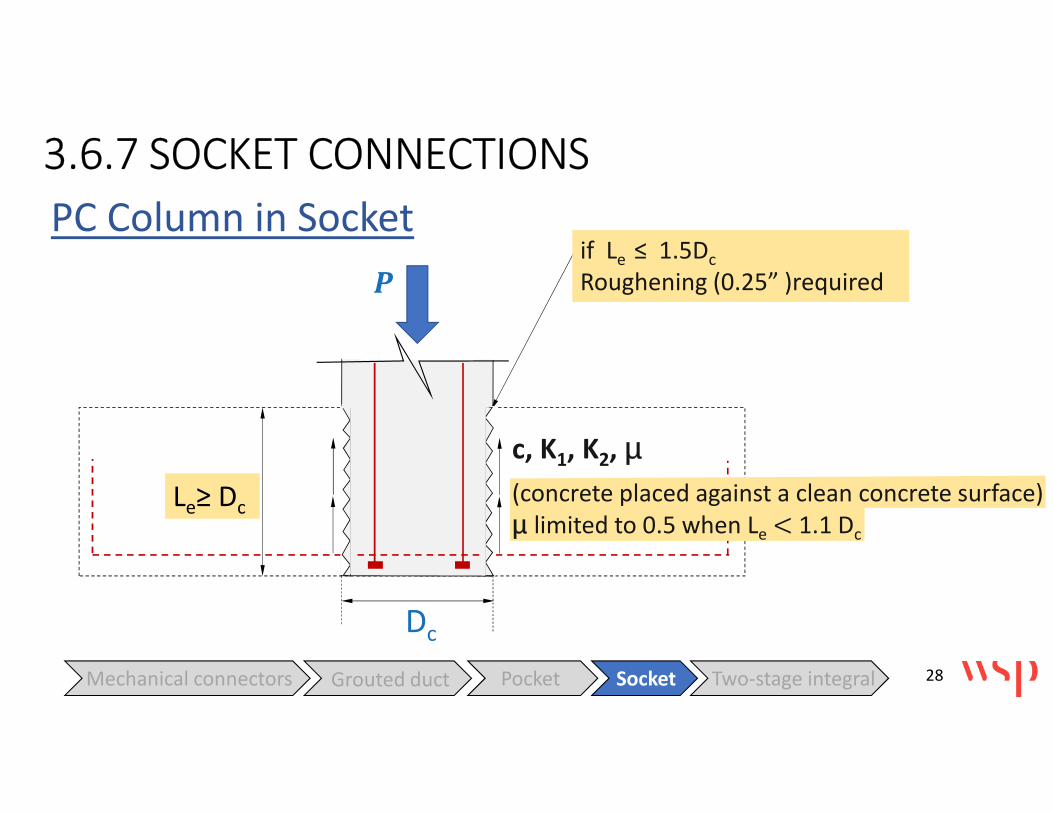
3.6.7 SOCKET CONNECTIONS
PC Column in Socket
V
Le≥ Dc
Dc
if Le ≤ 1.5Dc
Roughening (0.25” )required
c, K1, K2, µ(concrete placed against a clean concrete surface)
µ limited to 0.5 when Le < 1.1 Dc
Mechanical connectors Grouted duct Pocket Socket Two-stage integral 28

PC Column in Socket3.6.7 SOCKET CONNECTIONS
Mechanical connectors Grouted duct Pocket Socket Two-stage integral
Add’l confinement
bars at 45o
29

Socket in Shaft3.6.7 SOCKET CONNECTIONS
Spiral/Hoops Requirement
X�YZ[\] ≥ ^1_0X02a12b���
(^ = 0.5)
(^ = 1.0)
(^ = 2.0)
A
B
C
Location
le
≥ ls
+ e + cover
A
B
1’-0”
(^ = 1.0)
C
Le
Le /2
Le /2
covere
Mechanical Heads, if
used
cover
ls
Dc
Inte
ntio
na
l ro
ug
he
nin
g r
eq
uir
ed
fo
r L
e ≤
1.5
Dc
Mechanical connectors Grouted duct Pocket Socket Two-stage integral 30
[AASHTO ABC EQ. 3.6.7.3.2-1]
[AASHTO ABC EQ. 3.6.7.3.1-1]

3.6.12 TWO-STAGE INTEGRAL PIER CAP
1) LOWER PIER CAP 2) GIRDERS ERECTED 3) UPPER-STAGE CAP CAST
Mechanical connectors Grouted duct Pocket Socket Two-stage integral 31

3.6.12 TWO-STAGE INTEGRAL PIER CAP
Bcap
Ds1
Ds2
Dc
Joint Proportioning for SDC C&D or Seismic Zones 3 & 4
Mechanical connectors Grouted duct Pocket Socket Two-stage integral 32

Thank you!
wsp.com