seismic isolation of bridges in cold climates … · seismic isolation of bridges in cold climates...
TRANSCRIPT
1
SEISMIC ISOLATION OF BRIDGES IN COLD CLIMATES USING
LEAD RUBBER BEARINGS
Carlos Mendez-Galindo, Borja Baillés and Gianni Moor
Biography: Carlos Mendez-Galindo, born in 1981, received his PhD in earthquake and
structural engineering from Hokkaido University in Japan. He is currently Manager for
Seismic Devices at Mageba International, and General Manager at Mageba Mexico. He has
twice been presented with the Best Young Researcher Award by the Japanese Society of
Steel Construction, in 2006 and 2007, and is a member of IABSE, where he serves on the
working group “Earthquake Resistant Structures” and other scientific committees.
Borja Bailles, born in 1984, received his civil engineering degree from the Technical
University of Catalonia (UPC). He joined Mageba in 2010, and since transferring to the
company’s New York offices in 2015 has been Area Manager for the Canadian and Latin
American markets.
Gianni Moor, born in 1968, received his civil engineering degree from the Swiss Institute of
Technology in Zurich, Switzerland (ETHZ), and was later awarded an MBA degree by the
Business School IESE (Barcelona, Spain). Today, he is Deputy General Manager and COO
of Mageba Group, and CEO of Mageba USA.
ABSTRACT
This paper describes the development of a seismic isolation system using LRBs for highway
bridges where low temperatures must be considered in the design. Specifically, the LRBs must
be able to withstand temperatures as low as -30 C for up to 72 hours, while displaying only
minor variations in their effective stiffness. This extreme condition required the development
2
of a new rubber mixture, and the adjustment of the general design of the isolators. Because the
relevant specifications, such as AASHTO Guide Specifications for Seismic Isolation Design
and EN 15129: Anti-Seismic Devices, contain only limited test data relating to low-temperature
performance, extensive full-scale low-temperature dynamic testing was performed. This
unprecedented and demanding testing, which sheds new insight on the performance of LRBs
at low temperatures, is described.
Keywords: lead rubber bearings (LRB), low temperature, highway bridges, seismic isolation,
full-scale testing
INTRODUCTION
Increasing awareness of the threats posed by seismic events to critical transport infrastructure
has led to the need to seismically retrofit highway viaducts and other bridges to improve their
ability to withstand a strong earthquake. Continually evolving technology and the improving
evaluation and design abilities of practitioners have also contributed to the need for such
solutions - as have, of course, increasingly stringent national design standards.
SEISMIC ISOLATION OF HIGHWAY BRIDGES
Bearings have historically been among the most seismically vulnerable components of bridges.
Steel bearings in particular have performed poorly and have been damaged by relatively minor
seismic shaking1. Therefore, a strategy of seismically isolating a bridge’s superstructure, by
replacing such vulnerable bearings with specially designed protection devices, has much to
offer.
Seismic isolation systems provide an attractive alternative to conventional earthquake
resistance design, and have the potential for significantly reducing seismic risk without
compromising safety, reliability, and economy of bridge structures. Furthermore, with the
3
adoption of new performance-based design criteria, seismic isolation technologies are likely to
be increasingly used by structural engineers because they offer economical alternatives to
traditional earthquake protection measures2.
Seismic isolators provide the structure with enough flexibility so that the natural period of the
structure is shifted out of the range of predominant earthquake energy frequencies, as shown
in Fig. 1. This prevents the occurrence of resonance, which could lead to severe damage or
even collapse of the structure.
An effective seismic isolation system should provide effective performance under all service
loads, vertical and horizontal. Additionally, it should provide enough horizontal flexibility to
shift the natural period of the isolated structure sufficiently outside of the range of predominant
earthquake energy frequencies to satisfactorily reduce its response. Another important
capability of an effective isolation system is re-centering, even after a severe earthquake, so
that residual displacements that could disrupt the serviceability of the structure are minimized.
Finally, it should also provide an adequate level of energy dissipation, mainly through high
ratios of damping (Fig. 1), in order to control the displacements that otherwise could damage
other structural elements.
Application in Bridges
Bridges are ideal candidates for the adoption of base isolation technology due to the relative
ease of installation, inspection and maintenance of isolation devices. Although seismic
isolation is an effective technology for improving the seismic performance of a bridge, there
are certain limitations on its use. As shown in Fig. 1, seismic isolation improves the
performance of a bridge under earthquake loading partially by increasing the fundamental
vibration period. Thus, the vibration period of a bridge is moved away from the high-energy
seismic ground period and seismic energy transfer to the structure is minimized. Therefore, the
4
use of seismic isolation on soft or weak soil, where high period ground motion is dominant,
reduces the benefits offered by the technology3.
The seismic isolation system has a relatively high vibration period compared to a conventional
structure. Based upon principles of structural dynamics, increasing the difference between the
natural frequency of the isolated superstructure and the predominant earthquake input
frequencies reduces the seismic energy transferred into the superstructure. Therefore, seismic
isolation is most effective in relatively rigid structural systems and will provide limited benefits
for highly flexible bridges. Another consideration is related to the large deformations that may
occur in seismic base-isolation bearings during a major seismic event, which causes large
displacements in a bridge deck. This may result in an increased probability of collision between
deck and abutments. Damping is crucial to minimize the seismic energy flow to the
superstructure and to limit the horizontal displacements of the bearings2.
LEAD RUBBER BEARINGS
Among the great variety of seismic isolation systems, Lead Rubber Bearings (LRB) have found
wide application in bridge structures4. This is due to their simplicity and the combined isolation
and energy dissipation functions in a single compact unit. Using hydraulic jacks, the
superstructure of a bridge that requires seismic retrofitting can typically be lifted to remove the
original bearings, easily replacing them with suitable LRBs.
LRBs consist of alternate layers of natural rubber (NR) and steel reinforcement plates of limited
thickness, and a central lead core (Fig. 2). They are fabricated with the rubber vulcanized
directly to the steel plates, including the top and bottom connection plates, and can be supplied
with separate anchor plates, facilitating future replacement.
LRBs limit the energy transferred from the ground to the structure in order to protect it. The
rubber/steel laminated isolator is designed to carry the weight of the structure and make the
5
post-yield elasticity available. The rubber provides the isolation and the re-centering. The lead
core deforms plastically under shear deformations at a predetermined flow stress, while
dissipating energy through heat with hysteretic damping of up to 30%.
In practice, bridges that have been seismically isolated using LRBs have been proven to
perform effectively, reducing the bridge seismic response during earthquake shaking. For
instance, the Thjorsa River Bridge in Iceland survived two major earthquakes, of moment
magnitudes (Mw) 6.6 and 6.5, without serious damage and was open for traffic immediately
after the earthquakes as reported by Bessason and Haflidason5.
LRB bearings of seismically isolated bridges, due to their inherent flexibility, can be subjected
to large shear deformations in the event of large earthquake ground motions. According to
experimental test results, LRBs experience significant hardening behavior beyond certain high
shear strain levels due to geometric effects3.
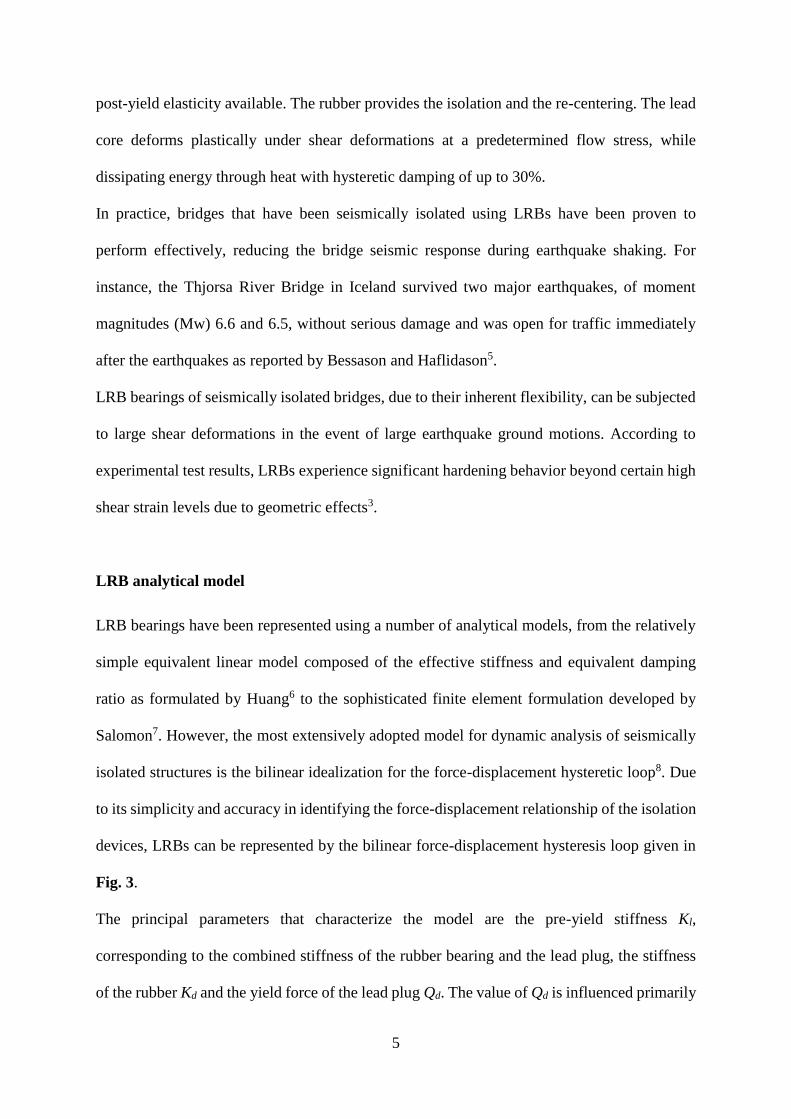
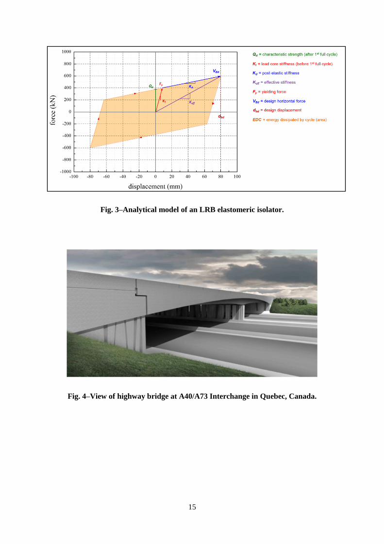
LRB analytical model
LRB bearings have been represented using a number of analytical models, from the relatively
simple equivalent linear model composed of the effective stiffness and equivalent damping
ratio as formulated by Huang6 to the sophisticated finite element formulation developed by
Salomon7. However, the most extensively adopted model for dynamic analysis of seismically
isolated structures is the bilinear idealization for the force-displacement hysteretic loop8. Due
to its simplicity and accuracy in identifying the force-displacement relationship of the isolation
devices, LRBs can be represented by the bilinear force-displacement hysteresis loop given in
Fig. 3.
The principal parameters that characterize the model are the pre-yield stiffness Kl,
corresponding to the combined stiffness of the rubber bearing and the lead plug, the stiffness
of the rubber Kd and the yield force of the lead plug Qd. The value of Qd is influenced primarily
6
by the characteristics of the lead plug, but it is important to take into account that in cold
temperatures, the value of Qd generally increases. Furthermore, the use of natural rubber
significantly increases stiffness, Kd, and thus also the corresponding force values.
Full scale testing of LRBs
Prototype testing is frequently required by contracts for the supply of LRB seismic isolators,
due to the fact that applications tend to be unique in various ways, considering both the
structure and the seismic characteristics of the region where it is located. An example of such
testing is included in the case study below.
CASE STUDY: HIGHWAY BRIDGE AT INTERCHANGE A40/A73 IN QUEBEC
The seismic isolation of bridges in cold climates is illustrated by the recent retrofitting of
seismic isolation bearings to an existing highway bridge, at the A40/A73 interchange, in
Quebec, Canada (Fig. 4). Guided LRBs were selected to support the entire bridge
superstructure in normal service and to protect the structure during an earthquake by isolating
it from the destructive movements of the ground beneath. The LRBs thus ensure the constant
serviceability of the structure, even after the occurrence of a strong earthquake, facilitating the
passage of emergency vehicles and contributing to the safety of the population.
The bridge has a two-span superstructure with concrete girders, with spans of 36m and 42m.
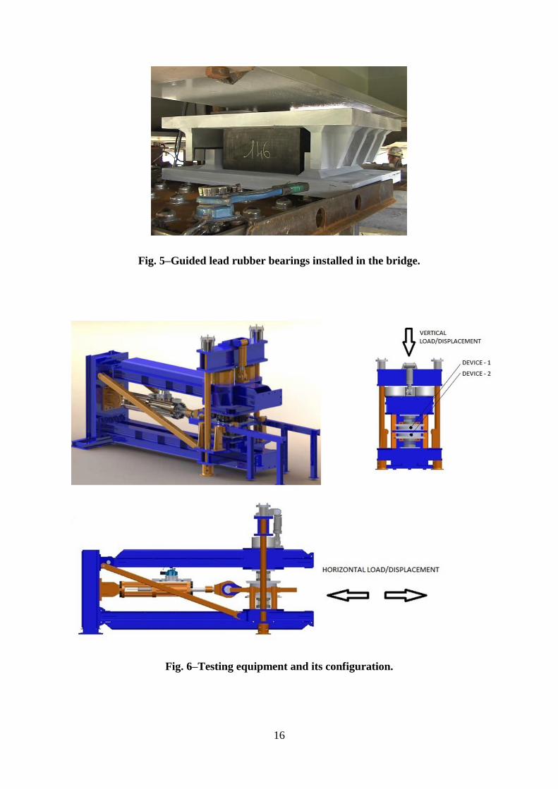
Design of the LRB
The LRBs (see Fig. 5) are of the guided type, with steel fittings preventing all transverse
movements. Each LRB has a vertical load capacity of approximately 3,250 kN – primarily to
serve its primary purpose of supporting the deck under normal service conditions. Due to the
structure’s location, the LRBs were designed for temperatures as high as 40°C (104°F) and as
7
low as -30°C (-22°F). In addition to these severe temperature conditions, the LRBs also had to
be designed to fulfill the following requirements:
1. Facilitate movements of up to 111 mm in the longitudinal direction
2. Prevent movements in the transverse direction
3. Provide damping of up to 30%
4. Dissipate hysteretic energy up to 58 kNm per cycle
5. Ensure re-centering following an earthquake
6. Increase the period of the deck of the bridge to more than 1.7 seconds
7. Transmit horizontal loads of up to 414 kN at an ambient temperature of 20°C (68°F)
8. Transmit horizontal loads of up to 530 kN at a low temperature of -30°C (-22°F)
These demands presented a significant challenge for design and manufacture – especially in
relation to low temperature performance. The bearings were designed to provide optimal
performance at 20°C and to minimize variations in dynamic characteristics at very low
temperatures. Considering the sensitivity of rubber to low temperatures, this was very difficult
to achieve. However, after a detailed analysis of the effects of temperature on the rubber and
the lead, and evaluation of the overall performance of the devices during extensive full-scale
testing (as described below), it was possible to develop an optimal solution according to
Canadian Highway Bridge Design Code CAN/CSA-S6. This solution included design of a new
rubber mixture – based on an extensive development program which included testing of a
number of rubber samples – and resulted in an adapted LRB design considering all conditions.
8
Prototype testing of LRBs
Prototype testing was carried out in accordance with the isolator supply contract, to verify the
performance of the LRBs in accordance with their design and the project specifications. The
testing included evaluation of the dynamic performance of each device in terms of effective
stiffness, damping, energy dissipated per cycle and other parameters such as displacements and
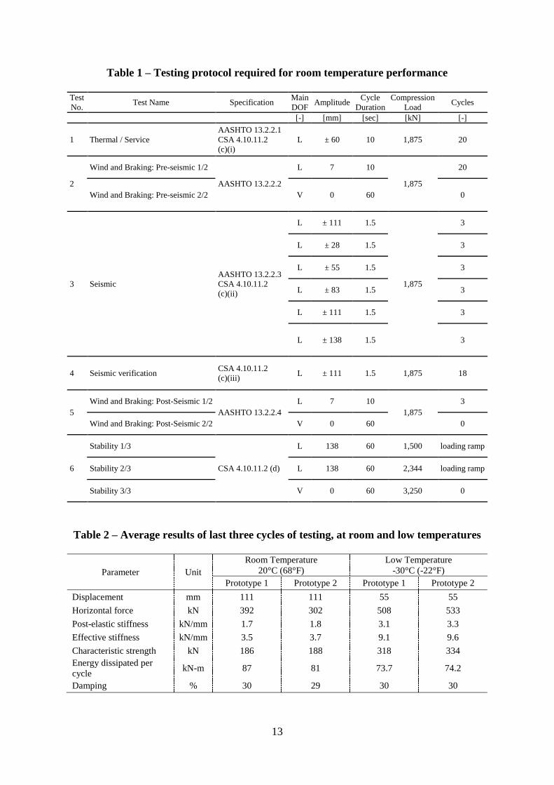
forces, as listed above. The testing protocol for room temperature testing is shown in Table 1.
Similar testing was required at the specified very low temperature. The test equipment and its
configuration, which allows simultaneous testing of two isolators, is shown in Fig. 6. The steel
frame holding the isolators was designed to counter the thrust forces that arise during testing
of seismic isolation devices.
The maximum horizontal load depended on the characteristics of the servo actuators installed,
and a nominal value of 1,400 kN was considered. The maximum vertical load of 10,000 kN
was provided by two actuators, each 5,000 kN. The project required consideration of both the
AASHTO Guide Specifications for Seismic Isolation Design (AASHTO GSSID) and the
Canadian Highway Bridge Design Code (CAN/CSA-S6-06). While AASHTO GSSID
requirements are well known and applied, the application of CAN/CSA-S6-06 requirements
presented an additional challenge. This code specifies in Section 4.10.11 the main requirements
for the testing of seismic isolation devices.
The specimens each had plan dimensions of 550 x 550 mm and a total height of 236 mm, and
were designed for a total design displacement of 111 mm and a test maximum vertical load of
3,250 kN. The samples were subjected to 23 different tests, most of them including dynamic
conditions, and with frequency and amplitude varying from one test to the next. For all dynamic
testing, a vertical load of 1,875 kN was applied to each of the samples.
9
The testing protocol presented in Table 2 fulfills all specified requirements, incorporating
necessary adjustments as required by the project engineer. The following special considerations
were taken into account for the prototype testing:
a. Room Temperature Tests (with isolators conditioned at a temperature of 20±5 °C for
48 hours prior to testing):
Three fully reversed sinusoidal cycles at amplitude of 111 mm and peak velocity
of 465 mm/s (frequency 0.67 Hz).
Three fully reversed sinusoidal cycles at amplitudes of 28, 55, 83, 111 and 138
mm (frequency 0.67 Hz).
b. Low Temperature Tests (with isolators conditioned at a temperature of -30 °C for 72
hours prior to testing):
Three fully reversed sinusoidal cycles at amplitudes of 28, 55 and 83 mm at a
frequency of 1 Hz.
c. Low Temperature Tests (with isolators conditioned at a temperature of -8 °C for 72
hours prior to testing):
Three fully reversed sinusoidal cycles at amplitudes of 111, 28, 55, 83, 111 and
138 mm at a frequency of 0.83 Hz.
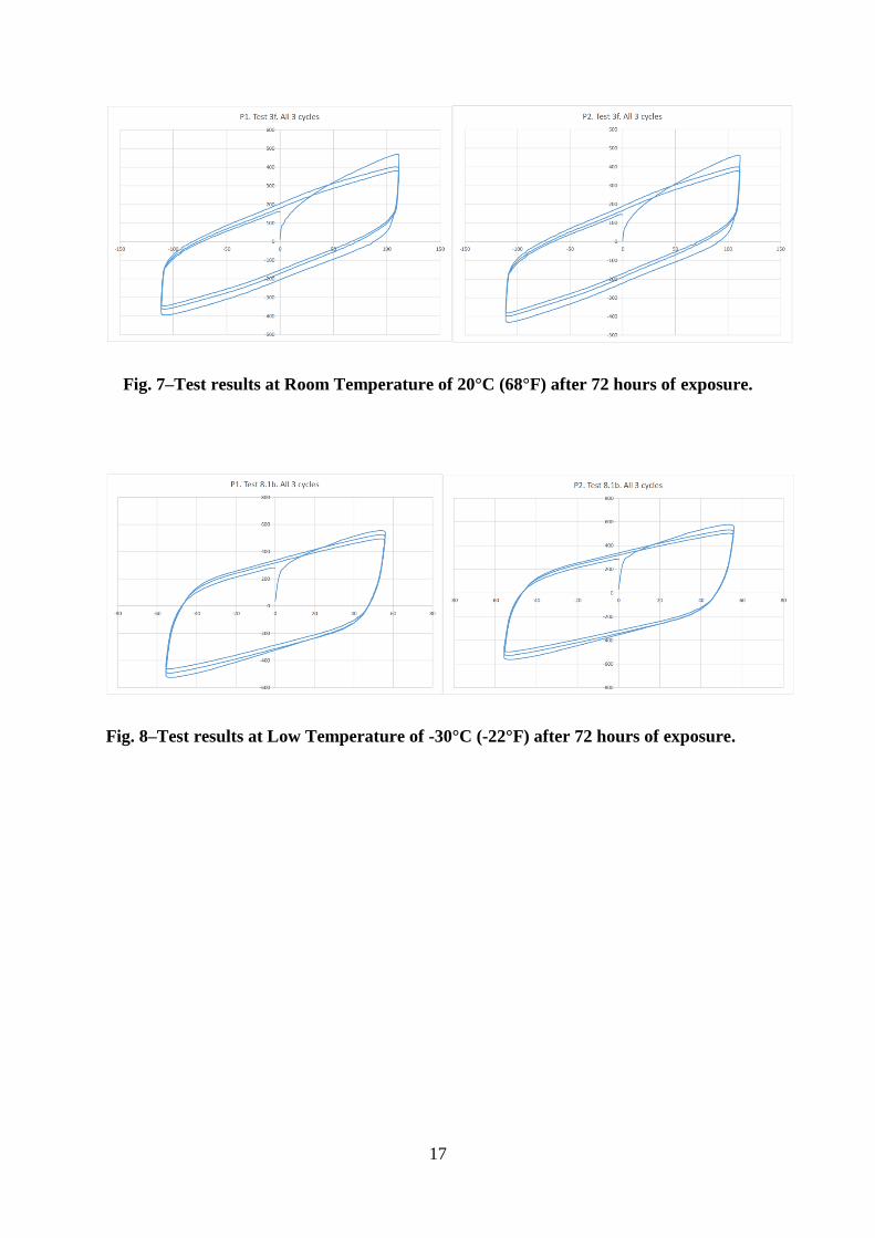
Results of low temperature testing
The extensive testing carried out on the two specimens provided a large amount of data. Here,
only the key performance at room temperature, and a comparison with the performance at low
temperature, are presented. Fig. 7 shows the main hysteretic responses at room temperature for
Prototype P1 and Prototype P2, and Fig. 8 shows the responses at low temperature in both
prototypes.
10
The results in Table 2 demonstrate that the key dynamic parameters such as effective stiffness,
horizontal force, post-elastic stiffness and characteristic strength increase by a factor of about
two at very low temperatures. However, considering the severe variation of temperature and
the strong dependence of rubber’s behavior on temperature, these results verified well the
effectiveness of these specially developed LRBs at low temperatures, as well as compliance
with the project specifications.
CONCLUSIONS
Lead rubber bearings, which are widely used to seismically isolate highway bridge structures,
display a significant vulnerability to low temperatures (e.g. -30 °C) unless designed and
fabricated for such conditions. In particular, their design should ensure that they display only
minor variations in their effective stiffness at such temperatures. As in the case study presented,
this may require the development of a new rubber mixture, the modification of the general
design of the isolators, and verification of low-temperature performance by means of extensive
full-scale prototype testing.
11
REFERENCES
1. Ruiz Julian, D., “Seismic performance of isolated curved highway viaducts equipped with
unseating prevention cable restrainers”, Doctoral Dissertation, Graduate School of
Engineering, Hokkaido University, Japan, 2005.
2. Mendez-Galindo, C., Hayashikawa T. and Ruiz Julian F. D., “Seismic damage due to
curvature effect on curved highway viaducts”, Proc. 14th World Conference on Earthquake
Engineering, IAEE, Beijing, China, 2008.
3. Turkington, D. H., Carr, A. J., Cooke, N. and Moss, P.J., “Seismic design of bridges on lead-
rubber bearings”, Journal of Structural Engineering, ASCE, Vol. 115, No. 12, 1989, pp. 3000-
3016.
4. Moehle, J. P. and Eberhard, M. O., “Chapter 34: Earthquake damage to bridges”, Bridge
Engineering Handbook, Boca Raton, CRC Press, 1999.
5. Bessason, B. and Haflidason, E., “Recorded and numerical strong motion response of a base-
isolated bridge”, Earthquake Spectra, Vol. 20, No. 2, 2004, pp. 309-332.
6. Huang, J. S. and Chiou, J. M., “An equivalent linear model of lead-rubber seismic isolation
bearings”, Engineering Structures, Vol. 18, No. 7, 1996, pp. 528-536.
7. Salomon, O., Oller, S. and Barbat, A., “Finite element analysis of base isolated buildings
subjected to earthquake loads”, International Journal for Numerical Methods in Engineering,
Vol. 46, 1999, pp. 1741-1761.
8. Mendez-Galindo, C., Hayashikawa T. and Ruiz Julian F. D., “Seismic performance of
isolated curved steel viaducts under level II earthquakes”, Journal of Structural Engineering,
JSCE. Vol. 55A, 2009, pp. 699-708.
12
TABLES AND FIGURES
List of Tables:
Table 1 – Testing protocol required for room temperature performance
Table 2 – Average results of the last three cycles of the prototype testing, at room and low
temperatures
List of Figures:
Fig. 1 – Reduction of acceleration by seismic isolation (left) and then additionally by
damping (right).
Fig. 2 – Cut-out view of a typical Lead Rubber Bearing.
Fig. 3 – Analytical model of an LRB elastomeric isolator.
Fig. 4 – View of highway bridge at A40/A73 Interchange in Quebec, Canada.
Fig. 5 – Guided lead rubber bearings installed in the bridge.
Fig. 6 – Testing equipment and its configuration.
Fig. 7 – Test results at Room Temperature of 20°C (68°F) after 72 hours of exposure.
Fig. 8 – Test results at Low Temperature of -30°C (-22°F) after 72 hours of exposure.
13
Table 1 – Testing protocol required for room temperature performance
Test
No. Test Name Specification
Main
DOF Amplitude
Cycle
Duration
Compression
Load Cycles
[-] [mm] [sec] [kN] [-]
1 Thermal / Service
AASHTO 13.2.2.1
CSA 4.10.11.2
(c)(i)
L ± 60 10 1,875 20
2
Wind and Braking: Pre-seismic 1/2
AASHTO 13.2.2.2
L 7 10
1,875
20
Wind and Braking: Pre-seismic 2/2 V 0 60 0
3 Seismic
AASHTO 13.2.2.3
CSA 4.10.11.2
(c)(ii)
L ± 111 1.5
1,875
3
L ± 28 1.5 3
L ± 55 1.5 3
L ± 83 1.5 3
L ± 111 1.5 3
L ± 138 1.5 3
4 Seismic verification CSA 4.10.11.2
(c)(iii) L ± 111 1.5 1,875 18
5
Wind and Braking: Post-Seismic 1/2
AASHTO 13.2.2.4
L 7 10
1,875
3
Wind and Braking: Post-Seismic 2/2 V 0 60 0
6
Stability 1/3
CSA 4.10.11.2 (d)
L 138 60 1,500 loading ramp
Stability 2/3 L 138 60 2,344 loading ramp
Stability 3/3 V 0 60 3,250 0
Table 2 – Average results of last three cycles of testing, at room and low temperatures
Parameter Unit
Room Temperature
20°C (68°F)
Low Temperature
-30°C (-22°F)
Prototype 1 Prototype 2 Prototype 1 Prototype 2
Displacement mm 111 111 55 55
Horizontal force kN 392 302 508 533
Post-elastic stiffness kN/mm 1.7 1.8 3.1 3.3
Effective stiffness kN/mm 3.5 3.7 9.1 9.6
Characteristic strength kN 186 188 318 334
Energy dissipated per
cycle kN-m 87 81 73.7 74.2
Damping % 30 29 30 30

14
Fig. 1–Reduction of acceleration by seismic isolation only (left) and then additionally by
damping (right).
Fig. 2–Cut-out view of a typical Lead Rubber Bearing.
15
Fig. 3–Analytical model of an LRB elastomeric isolator.
Fig. 4–View of highway bridge at A40/A73 Interchange in Quebec, Canada.
16
Fig. 5–Guided lead rubber bearings installed in the bridge.
Fig. 6–Testing equipment and its configuration.
17
Fig. 7–Test results at Room Temperature of 20°C (68°F) after 72 hours of exposure.
Fig. 8–Test results at Low Temperature of -30°C (-22°F) after 72 hours of exposure.