aar intermodal interchange rules - theccib.com · aar intermodal interchange rules ... panel...
TRANSCRIPT

AAR Intermodal Interchange Rules APPENDIX B
CORRECT UNIT REPAIR PROCEDURES
1/1/2016 –1–
APPENDIX B
CORRECT UNIT REPAIR PROCEDURES
B1. Introduction
a. Preface
This Appendix details procedures and methods for the repair of trailer, container, and chassis equipment to permit its safe return to service. The purpose of any repair is to restore the equipment to its original structural integrity. The OEM repair manual should be consulted first. If an OEM repair standard is not available, this Appendix describes the materials and method required by the AAR Intermodal Interchange Rules. All repairs and replacements are subject to the applicable provisions of this Code of Rules and all regulatory specifications.
This Appendix is divided into sections detailing repairs by component groups.
b. Proper Repairs
It is important that each area of defect on a unit be carefully evaluated and proper repairs and/or replacements be made. The types of unit defects discussed in this repair manual are not intended to indicate that they are the only types of structural defects that should be repaired. Each unit or area of defects should be reviewed individually and a repair decision made based on that review.
c. Equipment Component Compatibility
Original equipment components as manufactured, approved, and recommended by the builder of the unit are selected for their compatibility with each of the other elements of the unit; therefore, only original replacement parts or compatible materials should be used for recommended repairs.
d. Owner’s Requirements
If the owner’s standard(s) for applicable repair or replacement of specific component(s) are stenciled on the unit, such repair or replacement must be followed as prescribed in Rule 99.
e. Tamper Evidence Requirement
All repairs must be completed in a manner that makes it impossible to add or remove lading without visible traces of repair tampering.

AAR Intermodal Interchange Rules APPENDIX B
CORRECT UNIT REPAIR PROCEDURES
–2– 1/1/2016
B2. General Trailer/Container Repairs
a. Post and Panel Damage
Generally, post and/or panel damage can be repaired by splices and/or patches (refer to Body Repairs, following). If the extent of the damage is such that an effective structural repair by reinforcing the damaged area is questionable, replacement of parts is recommended rather than splicing and/or patching. All post and panel damage to be repaired should be evaluated on an individual basis and repairs made based on that review. In all cases, the original trailer or container manufacturer should be consulted for repair recommendations.
b. Joining Dissimilar Materials
Joining of dissimilar metals and other materials involves procedures that will, if done properly, prevent or control corrosion that may occur in certain atmospheric or moisture conditions. Improper application of protective coatings between surfaces of dissimilar metals can leave the materials open to severe galvanic actions. (In refrigerated trailers or containers, for example, when the space between two different metals is filled by a fluid that can conduct electricity, one of the metals will gradually decompose.) Corrosion also occurs when wood parts are not protected adequately prior to their assembly to metal surfaces.
The procedures listed below will, within practical limits, prevent such corrosion.
(1) Joining Aluminum to Unfinished Steel or Stainless Steel
(a) Before assembling aluminum to steel, including crossmembers to bottom rail, the surface of the steel must be cleaned of all rust, scale, weld flux, metal particles, and other foreign material.
(b) Immediately after cleaning:
1) Apply a primer to the steel surface to prevent galvanic action.
2) Apply a protective coating to the steel area.
3) Apply insulating tape.
(c) Exterior steel number and logo placards and similar exposed steel items shall be protected with insulating tape prior to assembly to an aluminum surface.
(d) Replacement fasteners must be of similar metals; screws, bolts, nuts, and nails; and protective coatings must be used.

AAR Intermodal Interchange Rules APPENDIX B
CORRECT UNIT REPAIR PROCEDURES
1/1/2016 –3–
(2) Joining Aluminum and Wood Components
(a) Apply a protective coating to wood surfaces.
(b) Sealers that are flexible and non-shrinking shall be used in highly corrosive areas to prevent deterioration of the wood, including trailer or container doors and door frame areas.
(3) Joining Metal to FRP Panels
(a) Although FRP (fiberglass reinforced plywood) panels are constructed with a fiberglass outer layer, a protective coating must still be applied between the steel component and FRP panel.
(b) Reference Joining Aluminum and Wood Components, Joining Aluminum and Wood Components, above, for correct procedures.
B3. Body Repairs (Side Panels)
a. Mating of Panels
Material selected for replacing side wall panels shall comply with the manufacturer’s recommendation, with corrugated or smooth panel construction mated under all circumstances, including patches. Prepainted panels must likewise be mated.
b. Patching Repairing Body Panels of Sheet and Post Trailers and Containers
(1) A patch panel of like material shall be made to overlap the existing panel break of not less than 1 in. on all sides for small repairs. On larger breaks, the damaged portion must be trimmed to produce a round or oblong opening. No patch shall be less than 4 in. on any one side (see Patching Panels).
Figure B-1 Patching Panels

AAR Intermodal Interchange Rules APPENDIX B
CORRECT UNIT REPAIR PROCEDURES
–4– 1/1/2016
(2) Aluminum and steel panel patches shall be the same thickness as the original.
(3) Clean and deburr both panel and patch. Smooth any dented or creased area around the damaged area.
(4) Place the panel patch over the break to include any badly dented or creased areas; drill holes for rivet securement around the patch perimeter, spaced on 1½ in. centers. Rivet holes shall be located not less than ½ in. from the edges of the patch.
(5) Apply a non-shrinking sealer between the patch and trailer body.
One bead must be applied around the perimeter of the damaged area. The other bead must be adjacent to the rivet line, and applied in a manner that does not allow an excessive amount of sealant to seep to the outside perimeter of the patch.
(6) A self-sealing pop rivet is the correct hardware to use on side panel repairs (excludes drive rivets and screws).
(7) For securement of panels to posts to the trailer or container structure, buck rivets and/or structural mono bolts must be used. Self-sealing pop rivets may be used only at the rail area where there is no rear access due to the trailer’s or container’s structural configuration.
(8) A patch cannot extend from one panel to another (Patching Panels).
Figure B-1a Patching Panels

AAR Intermodal Interchange Rules APPENDIX B
CORRECT UNIT REPAIR PROCEDURES
1/1/2016 –5–
(9) Cuts the full length of a single panel in the area of the top or bottom rail must be sectioned. Sections must be a minimum of 9 in. All sections must be buck riveted.
d. Panel Replacement of Sheet and Post Trailers and Containers
(1) Sufficient panel lap is required to provide both a good seal and proper installation (see (1)).
Figure B-3 Panel Overlay
(2) Place the panel over the opening and drill around the panel perimeter, placing the holes on 1½ in. centers. If an existing rivet hole is used, it must be reamed to provide a tight fit by use of a larger size rivet.

AAR Intermodal Interchange Rules APPENDIX B
CORRECT UNIT REPAIR PROCEDURES
–6– 1/1/2016
(3) The placement area and existing adjacent panels must be cleaned and deburred where they lap.
(4) Use applicable aluminum alloy or high tensile cadmium-plated steel rivets.
(5) For securement of panels to posts to the trailer or container structure, buck rivets and/or structural mono bolts must be used. Self-sealing pop rivets may be used only at rail area where there is no rear access due to the trailer or container structure configuration.
(6) A side post should never be spliced. If badly bent or cut, the interior post should be replaced before the section or full panel is replaced.

AAR Intermodal Interchange Rules APPENDIX B
CORRECT UNIT REPAIR PROCEDURES
1/1/2016 –7–
c. Patching Repairing Body Panel of Steel Container
Use of the correct type of steel, as well as proper surface preparation and painting methods, is critical.
(1) Straightening
Whenever possible, straighten dents and compression lines in panels by mechanical or hydraulic means without heating. It should not be necessary to use heat. Repairing a panel by straightening should return it to its original profile. If the damage has stretched the panel to such an extent that the original profile cannot be restored, repair by straightening should not be attempted.
(2) Straightening and Welding
To repair cracks, splits, cuts, tears, or pin holes when the original profile can be restored, straighten the damaged area: drill a stop hole at each end of any crack and weld the edges of the cut material to close the opening. Clean, mask, and prime the repaired area on both sides.
(3) Inserting
(a) If the damage cannot be repaired by straightening, a butt-welded insert may be installed (see Panel Insert). Inserts may straddle an existing panel weld seam if the damaged area is on or near such a seam. Inserts may not be suitable if the damage covers a large area adjacent to a rail or post or if nearby inserts are corroded or improperly installed and must be corrected.
Figure B-2 Panel Insert

AAR Intermodal Interchange Rules APPENDIX B
CORRECT UNIT REPAIR PROCEDURES
–8– 1/1/2016
(b) Remove any attachments (ventilators, marking plates, etc.) that are within the damaged area or near enough that they may be damaged during repair.
(c) Mark and cut out the damaged area with a torch or cutting disc. Cut the replacement material to size. Inserts must be fitted flush with the existing panel and should be fabricated to allow no more than 2 mm (5/64 in.) clearance between adjoining surfaces. Panel insert material must have the same corrugation size, profile, and radii as the original panel.
(d) Fit the insert into the cut-out area and tack weld in position. Continuously weld the insert on the exterior side of the existing panels. Ensure that insert welds fully penetrate the panel to the interior side.
(e) Clean, mask, and prime the repaired area on both exterior and interior sides. Apply top coat to the exterior side only.
(f) Replace markings removed during repair that are required by regulation or as directed by the owner. Reattach any other components that were removed during the repair.
Overlay
If the damage cannot be repaired by straightening, an overlay may be installed. Overlay is the same as inserting, except that the replacement material is slightly larger than the material being removed, and edges overlap the original material. Patching may be substituted for inserting on body panels..

AAR Intermodal Interchange Rules APPENDIX B
CORRECT UNIT REPAIR PROCEDURES
1/1/2016 –9–
Remove any attachments (ventilators, marking plates, etc.) that are within the damaged area or near enough that they may be damaged during repair.
Mark and cut out the damaged area with a torch or cutting disc. Overlay should overlap the existing panel on the exterior by ½ inch. In the case of corrugated panels, they should be fabricated oversize and must have the same corrugation size, profile, and radii as the original panel.
When installing the overlay, grind the existing panel to bare metal ¾ in from cut edges on the exterior side. This will provide a clean, smooth surface for the weld.
Fit the overlay into position over the cut-out area and tack weld in position. Continuously weld the patch on the exterior side of the existing panels.
Clean, mask, and prime the repaired area on both exterior and interior sides. Apply top coat to the exterior side only. Apply sealant around entire perimeter of the cut-out hole covered by the overlay on the interior.
Replace markings removed during repair that are required by regulation or as directed by the owner. Reattach any other components that were removed during the repair.
Panel replacement
If an individual panel cannot be repaired by straightening inserting, the damaged panel may be removed and replaced with new panels. Replacement may also be necessary if inserting would leave non-conforming repairs nearby or if replacement is less expensive. Butt-welded joints between the replacement and existing panels are required.
Remove any attachments (ventilators, marking plates, etc.) that are within the dam-aged area, or near enough that they may be damaged during repair.
Measure the width and depth of the damaged panel corrugation to determine what size material is required. Minor variations in the shape of the corrugations from the original are permitted, providing that the number of corrugations is the same as the original panel and the interior width of the container is not reduced.
Using a torch or disc cutter, cut the damaged panel away from the top and bottom rails and adjacent panels. Grind the cut areas smooth and clean.
The edges of the replacement panel should also be ground smooth and clean ensuring that the replacement panel butts against the remaining panels. The gap between the replacement and remaining panels should not exceed 5/64 in.
Fit the replacement panel into position so that the edges of the panel are flush with the edges of the remaining panels.

AAR Intermodal Interchange Rules APPENDIX B
CORRECT UNIT REPAIR PROCEDURES
–10– 1/1/2016
Tack weld the replacement panel in position; check that the alignment is correct; and then continuously weld in place. Where a lap joint is used to attach the replacement panel to a corner post, the lap must be at least 1/2 in and continuously welded on the exterior seam.
The interior seam of a corner post to panel lap joint should be skip-welded and sealed.
Clean, mask and prime the repaired area on both exterior and interior sides. Apply a top coat to the exterior side only. Replace markings removed during repair that are required by regulation or as directed by the owner. Reattach any other components that were re-moved during the repair.
Panel assembly (multiple panels) replacement
If damage to a side or front panel assembly cannot be repaired by straightening, inserting or replacement of individual component panels, the entire panel assembly must be re-moved and replaced. Replacement of a panel assembly may also be performed if it is more economical than a series of lesser repairs to the individual panels. It is im-portant to note that AAR dimensional tolerances can be affected when replacing the complete panel assembly. Dimensions must be checked before, during and after the repair operation to ensure that AAR tolerances are maintained.
Remove any attachments (ventilators, marking plates, etc.) that are within the dam-aged area, or near enough that they might be damaged during the repair process.
Measure the width and depth of the damaged panel corrugation to determine what size of material is required. Minor variations in the shape of the corrugations from the origi-nal panel are acceptable as long as the interior width of the container is not reduced.
Using a torch or disc cutter, cut the damaged panel away from the top and bottom rails and adjacent panels. Grind the cut areas smooth and clean.
The edges of the replacement panel should also be ground smooth and clean ensur-ing that the replacement panel butts against the remaining panels. The gap between the replacement and remaining panels should not exceed 5/64 in.
Fit and tack weld the replacement panels in position. The edges of replace-ment panels should butt together. Ensure that the lap at the corner post joints is a mini-mum of 1/2 in wide.
Continuously weld the panels to the top and bottom rails, corner posts and adjacent panels. Ensure full penetration to the interior of all butt welds. The interior seam of the corner post to panel lap joint should be skip-welded and sealed.

AAR Intermodal Interchange Rules APPENDIX B
CORRECT UNIT REPAIR PROCEDURES
1/1/2016 –11–
If the replacement panel assembly has not been blasted earlier, blast the panel to re-move abrasive residue. Clean, mask and prime the interior and exterior of the re-paired area. Apply a top coat to the exterior.
Replace markings removed during repairs that are required by regulation or as di-rected by the owner. Reattach any other components that were removed during the repair.
e. ) Panel Replacement of Steel Box Containers
If an individual panel cannot be repaired by straightening or inserting, the damaged panel may be removed and replaced with a new panel. Replacement also may be indicated if inserting would leave nonconforming repairs nearby or if replacement is less expensive. Butt-welded joints between the replacement and existing panels are required.
f. FRP Panel Damage
(1) General
In all cases, the original trailer or container manufacturer should be consulted for repair recommendations.
(2) Damage Categories
FRP panel damages normally fall under four categories:
(a) Minor surface damage—This damage requires only repair of the resin or surface finish. This may be accomplished by using the manufacturer’s recommended repair kit.
(b) Damage that goes through the glass fibers and into the plywood—This damage requires that the damaged area be cleared back to sound materials, and repaired with glass mat, resin, and surface finish.
(c) Puncture damage that goes completely through the panel—This damage requires that both faces of the panel be repaired.
(d) Severely smashed or damaged panels—In this case, the complete damaged area must be removed and replaced. In some cases, complete panel replacement may be necessary.

AAR Intermodal Interchange Rules APPENDIX B
CORRECT UNIT REPAIR PROCEDURES
–12– 1/1/2016
(3) Non-Puncture Damage Repair
(a) Determine the extent of the damage. Measure and mark a 4 in. area outside the damage, and draw in 2 in. lines for the feathered area. Score along the inside lines with a sander, and peel off all damaged fiberglass. Disc sand to remove all damaged plywood. Feather the area where exposed wood and fiberglass of the original panel meet. Remove dust. If moisture exits, dry with heat lamps.
(b) Using wide masking tape, make a rectangular border around the repair area. Sand the gel-coat surface inside the rectangle to roughen the smooth surface enough for good adhesion. Mix resin compound to accurate proportions and apply to the entire repair area. Fill in center depressions with an extra layer of resin to help eliminate air bubbles.
(c) Saturate a section of woven fiberglass with resin compound. Position it over both the wood and feathered area. Cover the entire repair area with remainder of the resin.
(d) Cut a piece of mylar film large enough to overlap onto the masking tape. Attach the top edge of film onto the top border of the tape. Use a roller to squeeze out excess resin compound, along with any air bubbles, level to the surface of the original panel.
(e) After curing is completed, sand the entire repair. Dust off, and fill small imperfections with polyester body filler or glazing compound. If a few pinholes persist after sanding the polyester, apply spot filler. Prime and paint if desired.
(4) Surface Repair
(a) The surface must be clean and dry before the patch can be applied. Remove all smoke and residual dirt from the repair area with clear, hot water, and then wipe dry with a clean, absorbent cloth.
(b) After removing any projecting fibers, apply polyester body filler mixed with an appropriate amount of cream hardener, leveling it so the surface is smooth and clean.
(c) From a roll of adhesive-backed repair film, cut a length slightly larger than the damaged area. Peel back the leading edge of paper liner and fold it down, exposing the adhesive surface.
(5) Replacement of Damaged Section
(a) Examine the severity of the damage. Tap the surrounding area to determine the extent of delamination. Mark a rectangle about 4 in. larger than apparent damage.

AAR Intermodal Interchange Rules APPENDIX B
CORRECT UNIT REPAIR PROCEDURES
1/1/2016 –13–
(b) Cut out the marked section. Inspect the perimeter for wetness. If moisture is present, drill small holes a few inches apart to determine the extent of moisture. Recut the opening larger if necessary.
(c) From inside the trailer or container, mark a line 2 in. from the opening to prepare to make a shiplap joint. Preset your saw to a depth half the thickness of the panel, then make the cut. Peel away the fiberglass part of the panel “sandwich” from the plywood.
(d) Remove the plywood to the depth of the cut with a chisel or router. Sand it smooth with a high-speed rotary sander and a 32-grit disc.
(e) Cut a plug from an FRP panel of the same thickness, 2 in. larger than the opening on all sides. Draw a line 2 in. in from the edge of the plug’s finished side. Cut to a depth half way through the panel. Remove the 2 in. strip of fiberglass and plywood, as previously described. Sand smooth. Clean the area. Place the plug in the opening, and then make necessary adjustments.
(f) Apply resin compound generously to cover all sanded areas. Fill all voids.
(g) Insert the plug of FRP panel. Place temporary fasteners, either screws or bolts, strategically around the perimeter to hold the plug in place until the resin compound cures. Remove excess resin compound. While the compound hardens, cut appropriate length 4 in. and 8 in. strips of woven fiberglass to cover all edges of the repair as preparation for lay-up later.
(h) When the compound has set up, remove the temporary fasteners and sand off any excess resin. Draw lines 2 in. on both sides of the joint. Using a sander or saw, score the fiberglass and remove a 2 in. strip on each side of the joint.
(i) Feather an additional 2 in. on all sides of the 2 in. strip of exposed plywood, working through the surface, but not through the woven fiberglass laminate. Sand with a back-and-forth motion to avoid heat build-up and possible delamination.
(j) After thorough mixing, completely cover sanded areas with the polyester resin compound. Lay a proper length of 4-in.-wide woven fiberglass on the resin-coated bare wood surface of the top horizontal section. Press the fiberglass into the moist resin. Immediately apply a thin layer of resin compound over the 4 in. strip, also covering the feathered area.
(k) Immediately lay on an 8 in. strip of woven fiberglass over the 4 in. strip, extending into the feathered original laminate, applying pressure to saturate the cloth. Follow with liberal amounts of additional resin compound.
(l) Cut a piece of film large enough to cover the lay-up. Tape the top edge of the film several inches above the top of the resin-covered area.
(m) With a roller, apply steady, continuous, firm pressure in one direction across the film-covered area to force out air bubbles and ensure complete saturation of the woven fiberglass. Discard excess resin. Repeat the same procedure for the

AAR Intermodal Interchange Rules APPENDIX B
CORRECT UNIT REPAIR PROCEDURES
–14– 1/1/2016
bottom horizontal section. Leave the film taped in place, and work on the outside of the trailer or container, repeating the previous steps.
(n) When the interior horizontal sections have cured, remove the mylar strips and lightly feather the corners to make smooth joints. Repeat this procedure on the vertical strips. Following horizontal curing, sand high points for a smooth surface. Also apply vertical strips to outside.
(o) Fill any small imperfections with polyester body filler or body glazing compound before and after sanding. If a few pinholes persist after sanding the polyester, apply spot filler and sand again until the desired finish is obtained.
(p) Mask off the patch, and prime the entire repair (if painting is desired). After the primer dries, spray on two coats of paint.
(q) The completed patch should offer the same structural integrity and near-perfect surface as the original fiberglass panel.
B4. General Interior Repairs
a. Floors
(1) Floor Structure and Damage
The floor of a trailer or container is a key element of the structural system. In addition to the normal vertical loads, it carries longitudinal loads such as dock bumps, etc. Floors in trailers or containers are normally of glued, laminated hardwood, that is, in most cases, one piece, the full length of the trailer or container, and approximately 12 in. wide. The trailer or container floor consists of three main structural components that serve to support a fork lift and to transfer the load to the side panels. These components include the floorboards, the floor supports or crossmembers, and the crossmember supports or crossmember-to-rail connectors.
The crossmember supports are the most critical of the three structural components, be-cause their failure could lead to the total collapse of the entire floor system.
Damage to floors is the result of overloading, mechanical handling trucks in the trailer, or deterioration of the floor well over the life of the trailer or container. This will result in sections that are weaker and will fail at a lower load level. Occasionally, a heavy piece of freight can puncture the floor in a local area, resulting in a floor failure.

AAR Intermodal Interchange Rules APPENDIX B
CORRECT UNIT REPAIR PROCEDURES
1/1/2016 –15–
(2) Flooring Repairs
Proper repairs to a broken floor section are mandatory, so that the integrity of the remaining floor is not affected by the repair. The following repair procedures must be followed:
(a) Flooring replacements shall fasten to a minimum of three crossmembers. No adjacent flooring repairs shall end on the same crossmember; however, end joints must be staggered and sealed (Floor Repairs).
Figure B-4 Floor Repairs
(b) All repairs to flooring or decking must be of a similar quality and like installation as the original flooring, be free of visible defects, and be top-coated/undercoated.
(c) Before starting repairs, it is recommended that an inspection of the crossmembers in the area of the board failure be made to determine if any crossmembers are in need of repair or replacement.

AAR Intermodal Interchange Rules APPENDIX B
CORRECT UNIT REPAIR PROCEDURES
–16– 1/1/2016
(d) In the event of floor area damage, determine the extent of the damage and indicate the extremes of the damage. Repair as follows:
1) From the point at which the damaged area stops, proceed in a forward and rearward direction at least one additional crossmember space, and mark the floor. Remove the floor screws in adjacent boards that will allow the damaged floor section to be raised above floor level, and cut the damaged boards at the points marked. Obtain an identical section, thickness, and variety of lumber for replacement.
2) Cut a section of the replacement lumber to a length compatible with the removed material. Apply a bead of butyl or silicone caulking to the mating perimeter edges of the floorboard, and lay in place, ensuring that the joint between adjacent boards interlocks.
3) Reinstall any missing fasteners in adjacent boards, and drill a minimum of three holes through the new board plank at each crossmember location. Install 2-in.-long self-tapping flat-head screws at each location.
4) Install a bead of caulk across the butt joint between the new and adjacent floor planks to ensure against leakage.
5) In situations where extensive damage is done to a floor and more than one floor board is damaged, be sure to install replacement planks so that no two adjacent butt joint conditions exist at any one crossmember. If necessary, stagger the joints by installing longer-than-required floor replacement inserts at adjacent positions. This is extremely important. Any distortion that results in the lack of contact between the floor and the crossmember can be remedied by reinstalling screws through the floor and positioning nuts on the bottom shank of the screw, thereby clamping the floor and crossmember together.
6) The butt gap between boards shall not exceed ¼ in. Floors
A) Floor Structure and Damage 1) The floor of a trailer or container is a key element of the structural system. In addition to the
normal vertical loads, it carries longitudinal loads such as dock bumps, etc. The trailer or con-tainer floor consists of three main structural components that serve to support a fork lift and to transfer the load to the side panels. These components include the floorboards, crossmem-bers and crossmember clips (crossmember-to-rail connectors).
2) If flooring requires repair, the method of repair should be the least aggressive necessary to correct the damage. The general order of aggressiveness, from least to most is: a) Cleaning b) Secure c) Dowel Repair d) Sectioning or Partial Replacement e) Complete Replacement

AAR Intermodal Interchange Rules APPENDIX B
CORRECT UNIT REPAIR PROCEDURES
1/1/2016 –17–
3) Floors in trailers or containers can be solid or laminated hardwood planks or plywood panels. All timber must be seasoned, with moisture content of less than 15% at time of installation.
B) General Repairs 1) Flooring replacements shall fasten to a minimum of three crossmembers. No adjacent floor-
ing repairs shall end on the same crossmember; however, end joints must be staggered and sealed.
2) All repairs to flooring must be of similar quality and like installation as the original flooring, be free of visible defects and be top-coated/undercoated.
3) Before starting repairs, it is recommended that an inspection of the crossmembers in the area of the board failure be made to determine if any crossmembers are in need of repair or re-placement.
C) Types of Repair (from least to most aggressiveness) 1) Cleaning
Depending upon floor conditions, it may be cleaned by the following methods: a) Sweeping (least aggressive) b) Wash with water, detergent or other cleaning agent c) Steam clean d) Sanding (most aggressive)
2) Secure a) Re-secure loose fasteners b) Replace broken or missing fasteners
3) Dowel Repairs Holes up to ½” in diameter may be repaired by injecting a round hardwood dowel into the hole and securing it in place with glue. Hole should be smoothed and dowel should be cut and smoothed to match the thickness of the floor board. a) Dowels must be round and made of hardwood. b) Dowels cannot exceed ½” in diameter. c) The minimum distance between the end of any floor board, plank or screw and any part of
the dowel is 2”. d) The minimum distance from the side of a floor board and any part of a dowel is one time
(1X) the dowel diameter. e) The minimum distance from any part of a dowel to any part of another dowel is four times
(4X) the larger dowel diameter.
Figure B-4 Floor Repairs

AAR Intermodal Interchange Rules APPENDIX B
CORRECT UNIT REPAIR PROCEDURES
–18– 1/1/2016
4) Sectioning or Partial Replacement – Plank Floor
Proper repairs to a broken floor section are mandatory, so that the integrity of the remaining floor is not affected by the repair. The following repair procedures must be followed: a) From the point at which the damaged area stops, proceed in a forward and rearward direc-
tion at least one additional crossmember space, and mark the floor. Remove the floor screws in adjacent boards that will allow the damaged floor section to be raised above floor level, and cut the damaged boards at the points marked. Obtain an identical section, thickness, and variety of lumber for replacement.
b) Cut a section of the replacement lumber to a length compatible with the removed materi-al. Apply sealant to the mating perimeter edges of the floorboard, and lay in place, ensur-ing that the joint between adjacent boards interlocks. Sealant exposed to cargo-carrying surfaces should not be of butyl material, but rather of urethane or chloroprene material suitable for contact with cargo.
c) Reinstall any missing fasteners in adjacent boards, and drill a minimum of three holes through the new board plank at each crossmember location. Install 2” long self-tapping flat-head screws at each location.
d) Install a bead of sealant across the butt joint between the new and adjacent floor planks to ensure against leakage.
e) In situations where extensive damage is done to a floor and more than one floor board is damaged, be sure to install replacement planks so that no two adjacent butt joint condi-

AAR Intermodal Interchange Rules APPENDIX B
CORRECT UNIT REPAIR PROCEDURES
1/1/2016 –19–
tions exist at any one crossmember. If necessary, stagger the joints by installing longer than required floor replacement inserts at adjacent positions. This is extremely important. Any distortion that results in the lack of contact between the floor and the crossmember can be remedied by reinstalling screws through the floor and positioning nuts on the bot-tom shank of the screw, thereby clamping the floor and crossmember together.
f) The butt gap between boards shall not exceed ¼”. 5) Sectioning or Partial Replacement – Plywood Floor
a) Replacement plywood sections must extend from bottom rail to steel center support. If a center support is not present, one needs to be installed.
b) Longitudinally laid replacement boards must be cut so that joints with existing adjacent boards lie over the center of the top flange of a crossmember or outrigger.
c) Transversely laid boards must be as wide (in the longitudinal direction) as the original board.
d) Half of the original panel, approximately 4ft. x 4ft., must be replaced. e) The longitudinal butt joint between the original and replacement panel must be along the
center line of the container. f) If original floor was coated by the manufacturer, apply coating to the new wood and to ad-
jacent areas where coating was disturbed. g) Apply sealant along mating edges of new plywood section.
6) Complete Replacement – Plank Floor a) Follow procedures described in Sectioning of Partial Replacement – Plank Floor. b) When fitting the planks into place, insert wedges between the bottom side rails and the
adjacent floor plank to ensure that the planks fit tightly. 7) Complete Replacement – Plywood Floor
a) Follow procedures described in Sectioning or partial Replacement – Plywood Floor. b) If a plywood floor without a center support is being replaced, a center support must be in-
stalled before the flooring is fitted.
b. Side Liners
(1) Repair/replacement materials shall be the same quality, type, and thickness as the original liner material.
(2) The installation of ply-liners should use the same type fasteners as used in the original installation.
(3) If a ply-liner has a hole greater than 4 in., the ply-liner should be replaced.
c. Scuff Liner
The scuff liner and fasteners must be of like material as the original installation. Sectioning is acceptable, with end joints located at a side post.
d. Roof

AAR Intermodal Interchange Rules APPENDIX B
CORRECT UNIT REPAIR PROCEDURES
–20– 1/1/2016
If the trailer or container is equipped with a plywood liner, replacement must be of the same quality, type, and thickness as the original. (See Roof Repairs, Roof Repairs, for specific roof repairs.)
B5. Trailer or Chassis Support Repairs
a. Landing Legs
(1) Description
The landing leg system (see Leg Assembly, Driver and Support Frames and Supports) has been designed to provide a stable support for the trailer or chassis and is located from centerline of the kingpin. Manually operated landing gears must be of two speeds, and the legs must be equipped with heavy-duty wheels and/or pads and heavy-duty axles.

AAR Intermodal Interchange Rules APPENDIX B
CORRECT UNIT REPAIR PROCEDURES
1/1/2016 –21–
Figure B-5 Leg Assembly, Driver

AAR Intermodal Interchange Rules APPENDIX B
CORRECT UNIT REPAIR PROCEDURES
–22– 1/1/2016

AAR Intermodal Interchange Rules APPENDIX B
CORRECT UNIT REPAIR PROCEDURES
1/1/2016 –23–
Figure B-6 Support Frames and Supports
(2) Defects
When a landing gear lower leg and/or upper leg assembly is bent, damaged, or deformed to a point that will not allow free vertical travel, the leg(s) should be replaced.
The normal defects associated with non-functional landing gear are:
(a) Broken welds
(b) Loose fasteners (missing, broken, defective, or improper materials)
(c) Legs improperly adjusted
(d) Defective components (bent or broken)
(e) Dry or insufficient lubricant
(3) Repair Comparability Required
(a) If other than the original type legs are installed, the bolt patterns, gear ratio, and load rating must be compatible.

AAR Intermodal Interchange Rules APPENDIX B
CORRECT UNIT REPAIR PROCEDURES
–24– 1/1/2016
(b) Landing leg braces that have been bent or damaged should be straightened, if practical, or replaced, if necessary, with a new one of like kind or equal strength to the original.
(4) Component Replacement vs. Leg Replacement
When a landing leg is defective due to internal component failure without damage to the leg assembly, the components should be replaced, if necessary, in lieu of replacing the entire leg. Reassembly must include proper lubrication.
(5) Landing Gear Mounting Bracket
If damage to the landing gear mounting bracket is such that it is impractical to repair and it must be replaced, the replacement bracket must be of like kind as original equipment. The bolt-on type requires a direct one-for-one replacement, utilizing identical fastener patterns and sizes as the original installation.
(a) In replacing the weld-on bracket, care must be taken to remove the damaged bracket without distorting, bending, or cutting through mounting surfaces adjacent to the bracket. If this is not possible, crossmembers directly over the landing gear must also be replaced with the bracket.
(b) Mounting brackets must be attached as established on original equipment.
(6) Sand Shoes, Dolly Wheels, and Axles
When is it necessary to replace sand shoes, dolly wheels, and/or axles, the replacement must be of like size, shape, and strength as the opposite position and must be properly secured.
(7) Landing Gear Crank Handle
When it is necessary to replace the landing gear crank handle, the replacement must be of sufficient size and shape to clear the side of trailer or container and must store in existing storage retainer.
(8) Cross Shaft
When it is necessary to replace the cross shaft, the replacement must be of the same size, shape, and strength as that of the original equipment. A removable fastener must be used in installation.

AAR Intermodal Interchange Rules APPENDIX B
CORRECT UNIT REPAIR PROCEDURES
1/1/2016 –25–
B6. Roof Repairs
a. General
Roof repairs (see Roof Sheet Edge Treatment) are equally, if not more, important than repairs to the nose or side walls of a trailer or container. Correct materials and good workmanship can determine if there will be load damage caused by weather. Roof panels that have a tear or hole should be repaired to prevent structural failure and water damage to cargo. Generally, repairs consist of a relatively simple patch or replacing a section of roof panel the full width of the trailer or container, extending to the nearest roof bows adjacent to the damaged area. Certain procedures must, therefore, be followed when roof repairs are made.
B6.

AAR Intermodal Interchange Rules APPENDIX B
CORRECT UNIT REPAIR PROCEDURES
–26– 1/1/2016
Roof Repairs
a. General Repairs
Roof repairs are equally, if not more, important than repairs to the nose or side walls of a trailer or container. Correct materials and good workmanship can determine if there will be load damage caused by weather. Roof panels that have a tear or hole should be repaired to prevent structural failure and water damage to cargo. Generally, repairs consist of a relatively simple patch or replacing a section of roof panel the full width of the trailer or container, extending to the nearest roof bows adjacent to the damaged area. Certain procedures must, therefore, be followed when roof repairs are made.
b. Roof Patching - Aluminum
(1) Care must be exercised to ensure that roof repairs are properly extended to the roof bows and given a good exterior seal to afford maximum long life to the repair and to avoid loosening of roof sheet by flexing. Patch is not to be riveted through the roof bow.
(2) For small repairs, a patch shall be made to overlap the existing panel break of not less than 1 in. on all sides. On larger breaks, the damaged portion must be trimmed to produce a round or oblong opening (same as side panels). No patch shall be less than 4 in. on any one side.
(a) Aluminum patches shall be the same thickness and type as original roof sheet.
(b) Clean and deburr both panel and patch. Smooth any dented or creased area around damage.
(c) Placing the patch over the break, drill holes for rivet securement around the patch perimeter, spaced on 1½ in. centers. Rivet holes shall be located not less than ½ in. from the edges of the patch.
(d) Any roof bow damage shall be repaired prior to the application of the patch.
(e) Apply a sealer between the patch and roof sheet and around the edge of patch, with additional sealer placed over the exterior rivet heads.
(f) Roof patches must be secured with soft buck rivets to prevent flexing and rivet hole elongation. Where the underside of the roof is inaccessible, repairs must be made with self-sealing pop rivets. All roof bow repairs or replacements must be made with original type fasteners or two-piece rivets.

AAR Intermodal Interchange Rules APPENDIX B
CORRECT UNIT REPAIR PROCEDURES
1/1/2016 –27–
(g) Holes must be drilled in the leading ends of any stress crack.
(h) When the patch extends to the top rail, buck rivets must be used.

AAR Intermodal Interchange Rules APPENDIX B
CORRECT UNIT REPAIR PROCEDURES
–28– 1/1/2016
Figure B-7 Roof Sheet Edge Treatment

AAR Intermodal Interchange Rules APPENDIX B
CORRECT UNIT REPAIR PROCEDURES
1/1/2016 –29–
c. Roof Sheet Breaks More than 6 in.
Sections on roof sheet breaks in excess of 6 in. shall extend to and be secured adjacent to roof bows. If the trailer or container is so constructed, the section applied must be bonded to roof bows.
(1) If damage requires removal of original roofing from the top rail, the entire original roof sheet must be sectioned and replaced to the nearest end.
(2) If the roof has been previously sectioned in the area of damage, the new section must be extended beyond the previous section.
(3) Roof patch cannot exceed 12 in. × 36 in.
(4) If the area to be sectioned exceeds 30% of the trailer roof, the entire roof must be re-placed.
(5) No more than two sections shall make up the entire roof of a trailer. The center of the roof sheet of a trailer cannot be spliced.
d. Roof Replacement – Aluminum
(1) A one-piece aluminum sheet must be used for trailers.
(2) All damaged roof bows must be removed and replaced with new roof bows and secured at each end to the top rail by use of huck-type fasteners or manufacturer’s original-type fasteners
(3) After removal of the old roof sheet or container roof segment and subsequent to any roof bow replacement, all roof bows and rail gutters must be cleaned and deburred.
(4) Before installing new roof, apply a sealer on the roof rail or in the roof rail gutter around the entire trailer or container roof segment.
a. Trailer – Roof replacement extends from noserail to rear header
b. Container – Roof segments consist of Front (noserail to intermediate header), Center (intermediate header to intermediate header), Rear (intermediate header to rear header).

AAR Intermodal Interchange Rules APPENDIX B
CORRECT UNIT REPAIR PROCEDURES
–30– 1/1/2016
(5) The roof sheet must be secured to the front rail for trailer, and either the front rail or intermediate header for container spaced as recommended by the manufacturer.
(6) The trailer or container must be on a level ground surface when a new roof is applied. The new roof sheet must be stretched in place by using clamps or roof stretchers at the rear header of the trailer or container, or intermediate header for container. (This phase is very important to reduce the possibility of roof sheet flapping, which could cause flex cracking.)
(7) The sides of the new roof sheet must be affixed to the top rails and rear headers and/or intermediate header for containers according to the manufacturer’s specification.
e. Roof Bows
Roof bows that are broken or missing should be replaced. Due to the wide variety of designs, the original trailer or container manufacturer should be consulted for its recommendations on bow replacements.
f. Corrugated Steel Roof
(1) Container roof is made of self-supporting corrugated panels.
(2) Bends may be straightened without heating by using a jack, along with a flat hammer or mallet.
(3) To repair cracks, cuts, or holes when the original profile can be restored, straight-en the damaged area. Drill stop holes at each end of any crack. Weld edges of the cut/cracked material. Clean, mask, prime and top coat repaired area.
(4) If the damage cannot be repaired by straightening and welding, an insert or patch may be installed. Steel insert/patches shall be the same thickness and type as original roof panel.
a. Inserting
(1) If the damage cannot be repaired by straightening, a butt-welded insert may be installed. Inserts may straddle an existing panel weld seam if the damaged area is on or near such a seam. Inserts may not be suitable if the damage covers a large area adjacent to a rail or post or if nearby inserts are corroded or improperly installed and must be corrected.

AAR Intermodal Interchange Rules APPENDIX B
CORRECT UNIT REPAIR PROCEDURES
1/1/2016 –31–
(2) Mark and cut out the damaged area with a torch or cutting disc. Straight cuts are important when inserts are installed. Cut the replacement material to size. Inserts must be fitted flush with the existing panel and should be fabricated to allow no more than 2 mm (5/64 in.) clearance between adjoining surfaces. Panel insert material must have the same corrugation size, profile, and radii as the original panel.
(3) Fit the insert into the cut-out area and tack weld in position. Continuously weld the insert on the exterior side of the existing panels. Ensure that insert welds fully penetrate the panel to the interior side.
(4) Clean, mask, and prime the repaired area on both exterior and interior sides. Apply top coat to the exterior side only.
b. Overlay
(1) If the damage cannot be repaired by straightening, an overlay may be in-stalled. Overlay is the same as inserting, except that the replacement ma-terial is slightly larger than the material being removed, and edges overlap the original material. Overlay may be substituted for inserting.
(2) Mark and cut out the damaged area with a torch or cutting disc. Overlays should overlap the existing panel on the exterior by ½ inch. In the case of corrugated panels, they should be fabricated oversize and must have the same corrugation size, profile, and radii as the original panel.
(3) When installing the overlay, grind the existing panel to bare metal ¾ in from cut edges on the exterior side. This will provide a clean, smooth sur-face for the weld.
(4) Fit the overlay into position over the cut-out area and tack weld in position. Continuously weld the patch on the exterior side of the existing panels.
(5) Clean, mask, and prime the repaired area on both exterior and interior sides. Apply top coat to the exterior side only. Apply sealant around entire perimeter of the cut-out hole covered by the overlay on the interior.
c. Replacement
(1) It is important to note that AAR dimensional tolerances can be affected when replacing the complete roof assembly. Dimensions must be checked before, during and after the repair operation to ensure that AAR tolerances are maintained.
AAR Intermodal Interchange Rules APPENDIX B
CORRECT UNIT REPAIR PROCEDURES
–32– 1/1/2016
(2) Using a torch or cutting disc, remove the roof sheet from the top rails, tak-ing care to ensure that the rail is not damaged. Another option is to cut roof sheet inside the top rails leaving a strip attached to rail. Remove the strip from the rails by grinding away the weld seam with a disc grinder.
(3) Place the replacement panels in position. Tack weld panels in position, check alignment is correct and then continuously weld in place. For butt joints the gap between the replacement panels should not exceed 5/64 in.
(4) Clean, mask and prime the interior and exterior of the repaired area. Apply a top coat to the exterior only.

AAR Intermodal Interchange Rules APPENDIX B
CORRECT UNIT REPAIR PROCEDURES
1/1/2016 –33–
b. Patching Roof Sheet
(1) Care must be exercised to ensure that roof repairs are properly extended to the roof bows and given a good exterior seal to afford maximum long life to the repair and to avoid loosening of roof sheet by flexing. Patch is not to be riveted through the roof bow.
(2) For small repairs, a patch shall be made to overlap the existing panel break of not less than 1 in. on all sides. On larger breaks, the damaged portion must be trimmed to produce a round or oblong opening (same as side panels). No patch shall be less than 4 in. on any one side.
(a) Aluminum and steel patches shall be the same thickness and type as original roof sheet.
(b) Clean and deburr both panel and patch. Smooth any dented or creased area around damage.
(c) Placing the patch over the break, drill holes for rivet securement around the patch perimeter, spaced on 1½ in. centers. Rivet holes shall be located not less than ½ in. from the edges of the patch.
(d) Any roof bow damage shall be repaired prior to the application of the patch.
(e) Apply a sealer between the patch and roof sheet and around the edge of patch, with additional sealer placed over the exterior rivet heads.
(f) Roof patches must be secured with soft buck rivets to prevent flexing and rivet hole elongation. Where the underside of the roof is inaccessible, repairs must be made with self-sealing pop rivets. All roof bow repairs or replacements must be made with original type fasteners or two-piece rivets.
(g) Holes must be drilled in the leading ends of any stress crack.
(h) When the patch extends to the top rail, buck rivets must be used.
c. Roof Sheet Breaks More than 6 in.
Sections on roof sheet breaks in excess of 6 in. shall extend to and be secured adjacent to roof bows. If the trailer or container is so constructed, the section applied must be bonded to roof bows.
(1) If damage requires removal of original roofing from the top rail, the entire original roof sheet must be sectioned and replaced to the nearest end.

AAR Intermodal Interchange Rules APPENDIX B
CORRECT UNIT REPAIR PROCEDURES
–34– 1/1/2016
(2) If the roof has been previously sectioned in the area of damage, the new section must be extended beyond the previous section.
(3) If the area to be sectioned exceeds 30% of the roof, the entire roof must be replaced.
(4) No more than three sections shall make up the entire roof. (The splice on a stretch trailer is counted as one section and would therefore be a two-sectioned roof.) The center of the roof sheet cannot be spliced.
(5) Roof patch cannot exceed 12 in. × 36 in.

AAR Intermodal Interchange Rules APPENDIX B
CORRECT UNIT REPAIR PROCEDURES
1/1/2016 –35–
d. Roof Replacement—Aluminum (Dry Van or Container)
(1) A one-piece aluminum sheet must be used.
(2) All damaged roof bows must be removed and replaced with new roof bows and secured at each end to the top rail by use of huck-type fasteners or manufacturer’s original-type fasteners.
(3) After removal of the old roof sheet and subsequent to any roof bow replacement, all roof bows and rail gutters must be cleaned and deburred.
(4) Before installing new roof, apply a sealer on the roof rail or in the roof rail gutter around the entire trailer or container.
(5) The roof sheet must be secured to the front rail, spaced as recommended by the manufacturer.
(6) The trailer or container must be on a level ground surface when a new roof is applied. The new roof sheet must be stretched in place by using clamps or roof stretchers at the rear header of the trailer or container. (This phase is very important to reduce the possibility of roof sheet flapping, which could cause flex cracking.)
(7) The sides of the new roof sheet must be affixed to the top rails and rear headers according to the manufacturer’s specification.
e. Roof Bows
Roof bows that are broken or missing should be replaced. Due to the wide variety of designs, the original trailer or container manufacturer should be consulted for its recommendations on bow replacements.

AAR Intermodal Interchange Rules APPENDIX B
CORRECT UNIT REPAIR PROCEDURES
–36– 1/1/2016
General Repair policy for Corner Posts
1. Damage to corner posts can be repaired by straightening, inserting or complete replacement. No full–profile sectioning of any kind is allowed on front corner posts.
2. Whenever possible, damage should be corrected with straightening by hydraulic or mechanical means without heat. Heat may be used only when the corner post cannot be straightened without heating. If heat must be applied, the steel should only be heated in the damaged area and must not be heated beyond a dull cherry-red color: approximately 650 degrees, or a 650 de-gree temperature indicating heat stick.
a) Damage to corner posts that cannot be repaired by straightening can be repaired by in-stalling an insert.
b) A maximum of two inserts (check specific manufacturers recommendations) are al-lowed in a front corner post provided all limitations below are followed:
1) There are no maximum height limitations for front corner post inserts. Full height front corner inserts are acceptable.
2) When two inserts share a common weld, the total length of the horizontal plane of the common weld must not extend through more than half of the external cross-sectional profile of the post.
3) Inserts must be fitted flush with the original material and butt-welded.
4) Front corner post inserts may be rectangular, oval, or diamond shape.
5) No insert may share the same horizontal plane as another insert.
6) Inserts must be a minimum of 6” in length and must extend through at least 3” of the cross-sectional profile of the post.
7) An insert that would terminate within 6 inches of an existing insert must be extended to that insert to form a common weld.
8) A front corner post insert that would terminate within 12 inches of a corner fitting must be extended to the fitting, and must be at least 12 inches in length.

AAR Intermodal Interchange Rules APPENDIX B
CORRECT UNIT REPAIR PROCEDURES
1/1/2016 –37–
Improper Repairs to Corner Posts
2 inserts cannot be on the same plane
Insert cannot be full profile
Insert cannot end within 6” of castings
Inserts within 6” must be connected with common weld
Improper Repair Improper Repair Improper Repair Improper Repair

AAR Intermodal Interchange Rules APPENDIX B
CORRECT UNIT REPAIR PROCEDURES
–38– 1/1/2016
Correct Repairs to Corner Posts
Insert which would end within 12” of casting, must extend to cast-ing and be at least 12” in length
Inserts must be a minimum of 6” and ex-tend through at least 3” of cross-sectional pro-file
Inserts must be a mini-mum of 6” apart
Insert which would terminate within 6” of an existing insert must be extended to that insert to form a common weld
Full height front corner in-serts are ac-ceptable

AAR Intermodal Interchange Rules APPENDIX B
CORRECT UNIT REPAIR PROCEDURES
1/1/2016 –39–
B7. Rear Doors and Rear Frame
a. General
The rear doors (see Rear Door Assembly) are probably the most damaged component on an intermodal trailer or container; therefore, certain repair procedures must be followed to maintain the overall structural integrity of the trailer or container.
Figure B-8 Rear Door Assembly

AAR Intermodal Interchange Rules APPENDIX B
CORRECT UNIT REPAIR PROCEDURES
–40– 1/1/2016

AAR Intermodal Interchange Rules APPENDIX B
CORRECT UNIT REPAIR PROCEDURES
1/1/2016 –41–
The door of a trailer or container is designed so that when loaded beyond the design load, failure will take place in the door locking hardware and not in the connections between the end frame (see Rear Frame Assembly) and the trailer or container body. The door and assembly are designed to withstand the maximum loads and fatigue forces imposed in rail operation. (Generally, the door end assembly consists of the door frame, doors, door hinges, door locking hardware, and the attachment of these items.)
Figure B-9 Rear Frame Assembly

AAR Intermodal Interchange Rules APPENDIX B
CORRECT UNIT REPAIR PROCEDURES
–42– 1/1/2016

AAR Intermodal Interchange Rules APPENDIX B
CORRECT UNIT REPAIR PROCEDURES
1/1/2016 –43–
b. Repair Procedures
(1) Rear Doors
(a) Plating of rear doors is not permitted and shall not be considered a proper repair (except as only a temporary repair). Self-sealing patches are allowable on cuts that do not extend more than 1/8 in. into the door plywood.
(b) All door replacements shall be made with like materials (gaskets, door hardware, door dimensions).
(c) When doors are mounted, they shall be mounted flush with the door frame and shall be constructed such that the curbside door must be opened before the roadside door can be opened.
(d) All decals and signs shall be replaced on new doors.
(e) The replacement of all tie-backs on new doors is required.
(2) Security Hardware
(a) Lock rods and hinge plates shall meet AAR M-931 specifications.
(b) When doors are replaced, the security plate must be replaced.
(c) All door-seal locking devices, door securement hardware, and door attachment hardware must be affixed by fully welding or by the use of “tamper-proof” fasteners to preclude entry into the trailer or container by removal of any of the door hardware components. A minimum of one fastener on each of the top and bottom hinges and top and bottom lock-rod support bearings shall be “tamper-proof.” All door seal hasp fasteners also shall be “tamper-proof.”
1) Fasteners may be considered “tamper-proof” by virtue of their original design or because of alteration to reusable fasteners, which requires their destruction by burning or cutting to effect removal. Reusable fasteners, such as nuts and bolts, are not recommended; if used, they must be secured by fully welding the nut to the bolt or the bolt to its mating hardware. (Fully welding means welding around the entire circumference of the bolt.) Prevailing-torque fasteners utilizing deformed threads or plastic inserts are not considered as “tamper proof” fasteners (except when they are inaccessible, such as on refrigerated trailer doors). Tack or spot welding is not permissible.
(d) All door hardware shall have a hot-dip galvanized finish or functional equivalent.

AAR Intermodal Interchange Rules APPENDIX B
CORRECT UNIT REPAIR PROCEDURES
–44– 1/1/2016
(3) Rear Door Frame
(a) Rear door headers are designed to protect all lights and wiring from mechanical damage during normal operations.
(b) Rear door lower sills are designed to protect lights, reflective lenses, and door lock keepers from mechanical damage during normal operations, as typified by backing into loading platforms and railcar bridge plates rubbing against the trailer during transit. Replacement rubber or fabric-type bumpers do not meet this requirement.
B8. Splicing of Side Rails and Protectors
a. General Repair Procedures
Damages to the top or bottom rails will directly affect the overall integrity of the trailer or con-tainer and if not properly handled, could cause the total failure of the equipment. The following considerations are involved with this type of repair (see “Rule of Thumb” for Trailer Splicing, Splicing of Top Rails, and Splicing of Bottom Rails):
(1) Manufacturer’s recommendations for repairs to top or bottom rail must be followed, with all splices adding adequate strength to the damaged area.
(2) No more than one splice per rail is allowed, except to a stretch trailer (see below).
b. Aluminum Trailers
(3) (1) A spliced rail section shall not exceed 25% of the overall vehicle length. (Refer to “Rule of Thumb” for Trailer Splicing)
(4) Splice Plates
(a) (2) Splice plates must be of steel and/or aluminum; insulating tape must be used between the aluminum and steel components.
(b) (3) The bottom rail splice plate must extend a minimum of three crossmembers, and the top rail splice plate must span a minimum of two posts.
(c) (4) Splice plates on the top rail (per manufacturer specifications) can be installed on either the interior or exterior of the rail.
(5) When a rivet is replaced with a bolt in a crossmember, it must have a minimum of at least a Grade 5 bolt with a self-locking nut. Lock washers may never be used.

AAR Intermodal Interchange Rules APPENDIX B
CORRECT UNIT REPAIR PROCEDURES
1/1/2016 –45–
(6) The welding or plating of top or bottom rails as a means of a repair is prohibited if it directly affects the strength and/or integrity of the rail.
(7) Stretch Trailers
A stretched trailer has been modified by the original manufacturer’s specifications. Therefore, the stretch portion of the rails shall not be considered a splice.
Figure B-10 “Rule of Thumb” for Trailer Splicing

AAR Intermodal Interchange Rules APPENDIX B
CORRECT UNIT REPAIR PROCEDURES
–46– 1/1/2016
If splice(s) exist(s) at any A location, then splice is permitted at any other A location(s). If splice(s) exist(s) at any B location, then splice is permitted at any other B location(s). Neither A location may be spliced if either B location on the same side is spliced. Neither B location may be spliced if either A location on the same side is spliced.
NOTE : No more than one splice section of rail is permitted in any top or bottom rail, except stretch trailers.

AAR Intermodal Interchange Rules APPENDIX B
CORRECT UNIT REPAIR PROCEDURES
1/1/2016 –47–
(2) Top Rail: no splice may be inserted farther than 5 feet from either stacking post. (3) Bottom Rail: no splice may be inserted farther than 10 feet from either stacking post.

AAR Intermodal Interchange Rules APPENDIX B
CORRECT UNIT REPAIR PROCEDURES
–48– 1/1/2016
(4) Splice plates must be of steel and/or aluminum; insulating tape must be used between the aluminum and steel components.
(5) The bottom rail splice plate must extend a minimum of three crossmembers, and the top rail splice plate must span a minimum of two posts.
(6) Splice plates on the top rail (per manufacturer specifications) can be installed on either the interior or exterior of the rail.
(5) (7) When a rivet is replaced with a bolt in a crossmember, it must have a minimum of at least a Grade 5 bolt with a self-locking nut. Lock washers may never be used.
(5) (8) Top Rail: lip or flange of the top rail can be repaired up to 12” by installing an angle as needed to fit cutout in the upper rail. When damage is larger than 12” a section or rail replacement may be required.
(6) (9) The welding or plating of top or bottom rails as a means of a repair is prohibited if it directly affects the strength and/or integrity of the rail.
(10) Bottom Rail: Overlay (plating) see Manufacturers recommendations. (Refer-ence/Stoughton Lower Rail Plating Recommendations for Minor Damage)

AAR Intermodal Interchange Rules APPENDIX B
CORRECT UNIT REPAIR PROCEDURES
1/1/2016 –49–
(d) Steel Container
(1) Straighten damaged Bottom Rails and Top Rails whenever possible. Straighten any dents, or other distortions to the component by hydraulic or mechanical means without heat. If heat must be applied, the steel should only be heated in the damaged area and must not be heated beyond a dull cherry-red color: approximately 650 degrees, or a 650 degree tem-perature indicating heat stick.
(2) Whatever method used must not adversely affect the structural integrity of the component nor restrict its safe operation.
(3) Welding or straightening and welding of cuts in a component or a weld joining compo-nents can, in many cases, be repaired by welding or a combination of straightening and welding. Straighten the damaged area, if necessary to restore original profile. Drill stop holes at each end of the cut. Weld the edges of the cut material, then clean, prime, and top coat according to manufacturer’s specifications.
(4) Damage to steel rails that cannot be repaired by straightening or welding can be repaired by installing an insert.
(a) Determine the length of the original component to be removed. Mark where the cuts are to be made and shield or temporarily remove any nearby wooden components to protect against burning damage. Remove the damaged area by flame-cutting with an oxygen-acetylene torch, disc grinding or other methods.
(b) Straighten the remaining edges of the adjoining area. Clean smooth all cut edges with a grinding disc.
(c) Cut to size and clean the replacement insert. The replacement material must have the same profile as the original and be of the same or higher quality, strength and thick-ness. Inserts must be fitted flush with the existing component and should be fabricated to allow no more than 5/64 inch clearance between adjoining surfaces.
(d) Tack weld in position, check alignment and continuously weld the insert on the exte-rior. Ensure that the insert welds fully penetrate the panel to the interior side.
(e) Reinstall any temporarily detached components and remove any shielding used during repair.
(f) Clean, mask, prime and top coat repaired area.

AAR Intermodal Interchange Rules APPENDIX B
CORRECT UNIT REPAIR PROCEDURES
–50– 1/1/2016
(5) Damage to a top rail that cannot be repaired by straightening or installing an insert may be repaired by replacing the damaged section of rail. When installing a replacement section, the entire cross-section profile of the rail must be removed.
(a) Sections must be a minimum of 6 inches and cannot end within 12 inches of a cast-ing. Any section welded to a casting must be a minimum of 12 inches. For repair steps see D (4) a through f.
(6) Damage to a bottom rail that cannot be repaired by straightening or installing an insert may be repaired by replacing the damaged section of rail. When installing a replacement section, the entire cross-section profile of the rail must be removed. For repair steps see D (4) a through f.
Acceptable bottom rail inserts

AAR Intermodal Interchange Rules APPENDIX B
CORRECT UNIT REPAIR PROCEDURES
1/1/2016 –51–

AAR Intermodal Interchange Rules APPENDIX B
CORRECT UNIT REPAIR PROCEDURES
–52– 1/1/2016
Definitions
(1) Top Rail Protectors
Top rail protectors are non-structural attachments at side rails, located near the top side, to protect the top rails and roof from contact with lift arms of lifting devices.
The bearing surface of top rail protectors is designed so as to prevent any contact of the lift arms of lifting devices with the trailer top rails or roof.
Top rail protectors are fastened to the trailer in a manner that prevents damage of top rail protector attachments by lift arms of lifting devices.
(2) Lift Pads (Bottom Rail Protectors)
Lift pads are non-structural attachments at bottom side rails to protect crossmembers, bottom side rails, side walls, and mechanical fasteners located near the bottom of the side and beneath the body from contact with lift shoes of lifting devices.
(a) The horizontal bearing surface of lift pads shall extend inwardly from the outside vertical plane of the body a minimum of 6 in. The vertical bearing surface shall extend upward from the bottom side rail a minimum of 2¼ in. See Trailer Lift Pads (Bottom Rail Protectors).
(b) Lift pads are fastened to the trailer in a manner that prevents damage of lift pad fasteners by lift shoes of lifting machines.
Figure B-10a Trailer Lift Pads (Bottom Rail Protectors)

AAR Intermodal Interchange Rules APPENDIX B
CORRECT UNIT REPAIR PROCEDURES
1/1/2016 –53–

AAR Intermodal Interchange Rules APPENDIX B
CORRECT UNIT REPAIR PROCEDURES
–54– 1/1/2016
Figure B-11 Splicing of Top Rails

AAR Intermodal Interchange Rules APPENDIX B
CORRECT UNIT REPAIR PROCEDURES
1/1/2016 –55–
Figure B-12 Splicing of Bottom Rails
B9. Riveting
a. General
A large portion of components on trailers and containers is engineered to be permanently fastened together by riveting. The importance of using correct riveting techniques cannot be overlooked in the discussion of proper trailer or container repairs. Listed below are some riveting techniques (refer to Proper Rivet Length, Good and Bad Rivet Heads, and Solid Rivet Chart — Sizes and Ratings).
b. Inspection Procedures for Locating Defective or Loose Rivets
There are several methods of detecting a loose or defective rivet.

AAR Intermodal Interchange Rules APPENDIX B
CORRECT UNIT REPAIR PROCEDURES
–56– 1/1/2016
(1) If a rivet can be turned or shaken with the fingers, it should be replaced.
(2) If looseness is suspected but cannot be verified by turning it, a sharp rap with a hammer will produce a dull sound in a loose rivet.
(3) A further check is to coat the rivet head with light oil, wait a few seconds for the oil to penetrate, wipe it clean, and rap it again with a hammer. If oil appears around the edges again, the rivet should be replaced.
(4) Finally, the appearance of evidence of movement or shifting between riveted parts, such as bare or shiny areas, is a good indication of the need for replacement.
c. Proper Riveting Procedures
(1) Select a rivet length so that the shank before riveting protrudes through the material 1½ times the diameter of the shank (Proper Rivet Length).
Figure B-13 Proper Rivet Length
(2) Tools
The two most important tools for producing a good rivet application are the rivet set and the bucking bar.
(a) Rivet Set
It is important to select and use the correct rivet set and size that will match the head of the rivet being used. An oversized set will flatten the rivet head and damage the adjacent material, while an undersized set will damage the rivet head. The rivet set is held in the gun by a retaining spring. Always be sure that the spring is securely in

AAR Intermodal Interchange Rules APPENDIX B
CORRECT UNIT REPAIR PROCEDURES
1/1/2016 –57–
place prior to starting. The strike of the rivet gun is adjustable and should be tested against a block of wood to ensure proper strike.
NOTE: Soft rivets are prohibited in trailer repairs, except on roof repairs.

AAR Intermodal Interchange Rules APPENDIX B
CORRECT UNIT REPAIR PROCEDURES
–58– 1/1/2016
(b) Bucking Bar
1) The bucking bar is used to produce the flat head (bucked head) on the opposite end of the rivet from the manufactured head. By using the correct bar properly, a bucked head should be produced that is 1½ times the diameter of the rivet shank and ½ the diameter in thickness.
2) The weight of the bar being used has an effect on the riveting job. If the bar is too light, it will require more action from the riveting gun and will consequently cause damage to the material. A heavy bucking bar will work faster and will keep the vibration of the gun from being transmitted to the mechanic’s hand.
3) Following are some of the basic rules for using a bucking bar:
a) One surface or side of the bucking bar is polished. This is known as the “face” and must be positioned and held correctly to create a proper bucked head.
b) Keep the face of the bar parallel to the material. If the bar is canted, the bucked head will be improperly formed, and the material will be damaged.
c) The face of the bucking bar must cover the entire rivet end.
d) A firm hold on the bar will result in a smoother and faster job and will prevent “chatter.”

AAR Intermodal Interchange Rules APPENDIX B
CORRECT UNIT REPAIR PROCEDURES
1/1/2016 –59–
Figure B-14 Good and Bad Rivet Heads

AAR Intermodal Interchange Rules APPENDIX B
CORRECT UNIT REPAIR PROCEDURES
–60– 1/1/2016
Figure B-15 Solid Rivet Chart — Sizes and Ratings

AAR Intermodal Interchange Rules APPENDIX B
CORRECT UNIT REPAIR PROCEDURES
1/1/2016 –61–

AAR Intermodal Interchange Rules APPENDIX B
CORRECT UNIT REPAIR PROCEDURES
–62– 1/1/2016
B10. Axles, Bearings, and Brakes
(See Axl and Axle/Brak)
a. General
Several components in this manual have been discussed as being integral components of the rail intermodal trailer or chassis; without the proper care and preventive maintenance, bearings and brakes in need of repair delay delivery of freight.
b. Brakes
(1) Brake Inspection
Cracked or broken drums, ruptured diaphragms, other chamber leaks, and missing, broken, or disconnected parts present imminently hazardous conditions likely to result in an accident or breakdown. Trailers or chassis never should be placed in service when any of these conditions exist.
(2) Brake Adjustments
(a) The axle must be raised so that the wheels are free from contact with the ground. Release the brakes; use shop air or tractor air and release the spring brakes, if the system employs spring-loaded parking or emergency brakes.
(b) While rotating the wheel, tighten the slack adjuster by turning the adjusting screw until the brake lining pressure stops rotation of the wheel. Back off this pressure with the adjusting screw until the brake shoe just releases the drum and allows wheel rotation again.
(c) An alternate method of adjusting the brakes without raising the wheels from contact with the ground, and probably the most frequently used, is to tighten the slack adjuster until the brake shoe is tight against the drum; then back off carefully until the shoe jerks slightly, indicating it has started to back away from contact with the drum. Strike the drum with a hammer and if drag still exists, the blow will produce a dull thud, indicating further clearance is required.
(d) When adjustment is completed, check the rod length on both sides for similarity so that application pressure is in balance. The angle made by the push rod and slack adjuster should be approximately 90° when service brakes are applied. Grease and lubricate where necessary to ensure that the linkage is operating without constraint; examine the position of the push rod at chamber exits to determine that it is not bent or rubbing.
(e) Automatic slack adjuster manufacturers have different procedures in the installa-tion and operation of adjusters. All automatic slack adjusters are designed to au-tomatically maintain a preset stroke or clearance. Self-adjusting brake adjusters

AAR Intermodal Interchange Rules APPENDIX B
CORRECT UNIT REPAIR PROCEDURES
1/1/2016 –63–
should not have to be manually adjusted. Manual adjustments can be made tem-porarily until an inspection and repair can be completed.
(3) Spring Brake Chambers
(a) WARNING: Spring brake chambers contain high-strength springs that are compressed even at the extended position in the chamber. This spring, if suddenly released, can propel itself or other parts of the brake chamber with enough force to seriously injure personnel.
(b) Recommendations of the spring brake chamber manufacturer should be followed carefully when inspecting, removing, repairing, servicing, disposing, or otherwise handling spring brake chambers.
(c) Spring brake chambers that are to be discarded should be safely disarmed before storage. Disarming should be accomplished in a disablement cage or other suitable safety device, using a method recommended by the manufacturer of the spring brake chamber.
(4) Brake Liners
(a) Shoes should be coated to prevent corrosion.
(b) Stainless steel clevis and pins should be used.
(c) Test to ensure shoe is in proper circumference.
(d) See Acceptable and Unacceptable Cracks in Shoes for acceptable/unacceptable cracks in shoes.

AAR Intermodal Interchange Rules APPENDIX B
CORRECT UNIT REPAIR PROCEDURES
–64– 1/1/2016
Figure B-16 Axle Assembly

AAR Intermodal Interchange Rules APPENDIX B
CORRECT UNIT REPAIR PROCEDURES
1/1/2016 –65–
Figure B-17 Axle/Brake Assembly

AAR Intermodal Interchange Rules APPENDIX B
CORRECT UNIT REPAIR PROCEDURES
–66– 1/1/2016
Figure B-17a Acceptable and Unacceptable Cracks in Shoes

AAR Intermodal Interchange Rules APPENDIX B
CORRECT UNIT REPAIR PROCEDURES
1/1/2016 –67–

AAR Intermodal Interchange Rules APPENDIX B
CORRECT UNIT REPAIR PROCEDURES
–68– 1/1/2016
B11. Upper Coupler and Kingpin
(Kingpin Wear Limits through Floorbed and Fram)
a. Kingpin
(1) Repair Restriction
No repair to the kingpin or any trailer or chassis in intermodal service is allowed without notification to the owner, and then kingpins may be repaired only in accordance with specific instructions from the manufacturer of the trailer or chassis.
(2) Kingpin Wear Limits
By permission of the Society of Automotive Engineers, the document SAE J2228 – King Pin Wear Limits, Commercial Trailers and Semi Trailers, forms a part of this specification to the extent specified herein. Unless otherwise specified, the current issue of this publication shall apply. All publications are subject to revision, and the users of this document should be certain they are using the current version. Copies of SAE J2228 can be obtained by contacting the Society of Automotive Engineers, 400 Commonwealth Drive, Warrendale, PA 15096.
(a) Scope
This provision applies to upper coupler kingpins for commercial trailers and semitrailers conforming to the dimensional requirements of SAE J700 when new and originally installed. The dimensions of SAE J700 are the frame of reference for this document.
(b) Purpose
The purpose of this document is to establish maximum parameters for kingpin wear, and to suggest a gauge configuration for inspecting kingpin wear. Kingpins exceeding the conditions of this specification must be removed from service and replaced.
(c) References
Applicable Document—The following publication forms a part of this specification to the extent specified herein. The latest issue of SAE publications shall apply.
SAE Publication—Available from SAE, 400 Commonwealth Drive, Warrendale, PA 15096.
SAE J700—Upper Coupler Kingpin—Commercial Trailers and Semitrailers
(d) Kingpin Wear Limits shows minimum diameters and allowable areas for wear on kingpins. Check diameter at several points around the kingpin to detect and

AAR Intermodal Interchange Rules APPENDIX B
CORRECT UNIT REPAIR PROCEDURES
1/1/2016 –69–
measure nonuniform wear conditions. Kingpin wear is restricted to areas shown in Kingpin Wear Limits in crosshatch. Wear on noncrosshatched areas is not acceptable.
Kingpin shows areas on the kingpin where nicks, burrs, gouges, etc., are allowed. However, no burr, nick, and/or gouge may exceed 3.2 mm (0.12 in.) in depth. The maximum number of nicks, burrs, gouges, etc., that exceed 1.5 mm (0.06 in.) in length should not exceed 10 on the 50.8 mm (2.00 in.) diameter. Nicks, burrs, gouges, etc., should not exceed 6.4 mm (0.25 in.) in length when measured at their maximum length.
Inspection of Kingpin Diameters Using One Type of Gauge and Kingpin Length and Squareness Check Using One Type of Gauge show a recommended gauge to inspect:
1) Wear on 50.8 mm (2.000 in.) diameter
2) Wear on 73.02 mm (2.875 in.) diameter
3) Kingpin length
4) Kingpin squareness to bolster plate
The gauge shown is of a “No Go” design, so any engagement of the gauge on the appropriate diameter indicates the kingpin is worn and must be removed from service and replaced.
Kingpin length, squareness, and bolster plate flatness must be in accordance with SAE J700. Check squareness at several points around the kingpin to detect an out-of-square condition.
Other gauge configuration and direct reading measurement devices, such as micrometers and dial calipers, also may be used.
b. Upper Coupler
Upper coupler attachment fasteners, when damaged, loose, or missing generally as a result of “scuffing and bottom rails,” should be replaced immediately for safe operation. These fasteners retain the upper coupler in position and play an important role in the overall trailer design. The quantities of these fasteners are based on the amount of shear load and forces introduced by the upper coupler. Any reduction of fasteners, whether damaged, loose, or missing, places the trailer at risk for continuous safe operation.

AAR Intermodal Interchange Rules APPENDIX B
CORRECT UNIT REPAIR PROCEDURES
–70– 1/1/2016
Figure B-18 Kingpin Wear Limits
Figure B-19 Kingpin Nicks, Burrs, Gouges
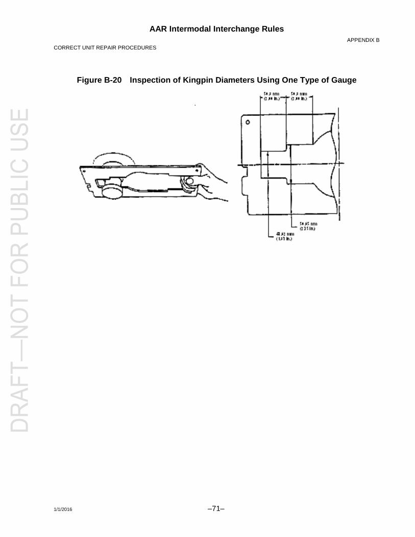
AAR Intermodal Interchange Rules APPENDIX B
CORRECT UNIT REPAIR PROCEDURES
1/1/2016 –71–
Figure B-20 Inspection of Kingpin Diameters Using One Type of Gauge

AAR Intermodal Interchange Rules APPENDIX B
CORRECT UNIT REPAIR PROCEDURES
–72– 1/1/2016
Figure B-21 Kingpin Length and Squareness Check Using One Type of Gauge
Figure B-22 Front Frame

AAR Intermodal Interchange Rules APPENDIX B
CORRECT UNIT REPAIR PROCEDURES
1/1/2016 –73–
Figure B-23 Floorbed and Frame Assembly

AAR Intermodal Interchange Rules APPENDIX B
CORRECT UNIT REPAIR PROCEDURES
–74– 1/1/2016
B12. Subassembly
(Subframe Assembly, Lower—FS Slider and Spring Assembly)
a. Locking Mechanisms
(1) Types
Siding undercarriages fall into one of three categories with regard to the manner in which they are locked into place beneath the trailer or chassis:
(a) Retractable pins operated by a pull handle or level on the slider
(b) Removable stop bars, one located in front, and one located in back of the slider
(c) A combination of retractable pins and a removable bar
(2) Safety Requirement
Regardless of the type of locking mechanism used, retractable pins and removable bars are the principal structural elements holding the slider in place beneath the trailer or chassis. If these are not maintained in proper working order, or if they are not utilized in the manner prescribed by the manufacturer, the slider can become detached from the trailer or chassis, and a serious accident can result.
b. Guide and Hold-Down Brackets
All guide and hold-down brackets must be in place and in good repair for safe operation. These brackets provide all or part of the lateral and vertical retention of the slider, and their maintenance is required for safe operation of the trailer or chassis.
c. Maintenance
(1) Perform scheduled maintenance of the suspension and slider per the manufacturer’s recommendation.
(2) Perform repeat examination of all components, especially the removable stop bar and/or locking pin mechanisms, on a regular basis during preventive maintenance or safety inspections.
(3) Replace worn or broken components with factory-approved replacement parts.

AAR Intermodal Interchange Rules APPENDIX B
CORRECT UNIT REPAIR PROCEDURES
1/1/2016 –75–
WARNING:Failure to check for proper locking pin engagement prior to driving away and failure to take proper preventive maintenance measures can lead to slider malfunction and possible accident, resulting in property damage, personal injury, or even death.
AAR Intermodal Interchange Rules APPENDIX B
CORRECT UNIT REPAIR PROCEDURES
–76– 1/1/2016
d. Air Rides
Air-ride suspension reduces tire wear, road wear, fuel consumption, and vibration.
System components must be maintained to prevent them from becoming damaged, worn, or misaligned. Any abnormalities such as loose or missing fasteners, bushing connections, or abnormal tire wear should be assigned for maintenance.
Anytime parts are replaced for service, damage, wear, or failure, complete suspension should be checked.

AAR Intermodal Interchange Rules APPENDIX B
CORRECT UNIT REPAIR PROCEDURES
1/1/2016 –77–
Figure B-24 Subframe Assembly, Lower—FS Slider

AAR Intermodal Interchange Rules APPENDIX B
CORRECT UNIT REPAIR PROCEDURES
–78– 1/1/2016
Figure B-25 Spring Assembly
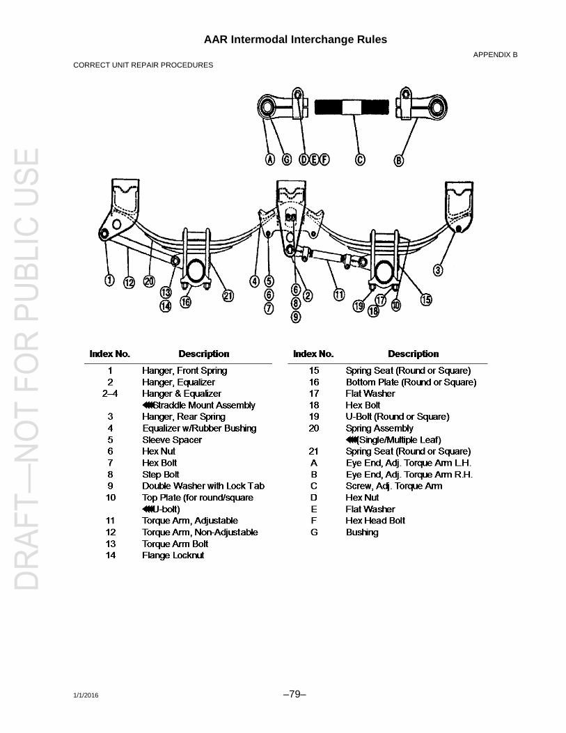
AAR Intermodal Interchange Rules APPENDIX B
CORRECT UNIT REPAIR PROCEDURES
1/1/2016 –79–

AAR Intermodal Interchange Rules APPENDIX B
CORRECT UNIT REPAIR PROCEDURES
–80– 1/1/2016
B13. Electrical and Air Systems
a. Electrical System
(1) Lighting System
(a) Lighting systems shall be 12-volt design with conventional seven-conductor electrical connector socket wires and be installed per Figure 1.
(b) The lighting system on trailers consists of a light connection located on the nose of the trailer, four red marker lights, two amber marker lights, four amber reflectors, two red reflectors, two combination stop and tail lights, one R.H. directional signal, one L.H. directional signal, one license plate light, auxiliary lights, and all the necessary wiring, wiring clips, terminals, and connectors for the correct functioning of the system to meet required Federal Motor Vehicle Safety Standard 108. Lights are recessed for protection from trailer sides and ends, with no opening permitted that will allow water into the system.
(c) Chassis lights consist of two combination stop and tail lights, one R.H. directional signal, one L.H. directional signal, and one license plate light. Lights are recessed for protection with no opening permitted that will allow water into the system.
(2) Protective Coating
It is recommended that dielectric grease be used as a protective coating on all electrical connectors to ensure longevity and performance of the electrical connection.
(3) Welding
Welding on trailers and chassis can be hazardous to sensitive electrical components such as lights. Before welding, check the following:
(a) All air lines are protected from heat and splatter.
(b) All anti-skid components are shielded and protected from heat and splatter.
(c) A ground clamp is placed as close to the weld as practical.
(d) Electrical trailer power cord must be disconnected from power unit.

AAR Intermodal Interchange Rules APPENDIX B
CORRECT UNIT REPAIR PROCEDURES
1/1/2016 –81–
b. Air System
(Air Connections and Air )
Air brake lines are designed to be accessible from the exterior of the trailer, normally running in the center of the trailer, accessible from beneath. Caution should be taken when working on the floor, crossmembers, etc., so as not to damage the integrity of the system.
WARNING:Air chamber diaphragm replacement is not recommended.
(1) Air Relay Valve Replacement
If relay valves require replacement as a result of corrosion or mechanical damage on trailers or chassis, replacement should be on a one-for-one basis with the OEM replacement. Do not install a relay valve that has a different manufacturer than the valve originally installed. Refer to the manufacturer for information on replacement valves.
(2) Drain Cock Manual Replacement
All air tanks have at the lower-most point a threaded boss and a manual rotating type valve, which allows bleeding air pressure and entrapped moisture, dirt, and debris from the tank. These valves, due to their constant exposure to moisture, do malfunction and are replaced with a similar type rotating valve by merely unthreading the defective valve and inserting a replacement component.
(3) Glad Hand Placement
Glad hands shall be mounted in the recessed portion of the nose of the trailer or chassis so as to make the glad hands flush or recessed, to prevent damage from impact to the nose of the trailer or chassis.

AAR Intermodal Interchange Rules APPENDIX B
CORRECT UNIT REPAIR PROCEDURES
–82– 1/1/2016
Figure B-26 Air Connections

AAR Intermodal Interchange Rules APPENDIX B
CORRECT UNIT REPAIR PROCEDURES
1/1/2016 –83–
Figure B-27 Air Actuation Brake System

AAR Intermodal Interchange Rules APPENDIX B
CORRECT UNIT REPAIR PROCEDURES
–84– 1/1/2016
B14. Tires
a. Safety Precautions
When working with tires, several safety precautions should be followed. Listed below are items to be considered:
(1) Do not reinflate a tire that has been run while flat without first inspecting the tire, rim, and wheel assembly. A tire that is 20% under-inflated is considered flat. Tire should be inspected for defects. Double-check the lock ring for damage; make sure it is secure in the gutter before inflation.
(2) Always exhaust all air from both tires of a dual assembly prior to removing any rim components or any wheel components, such as nuts and rim clamps. Make sure you remove the valve core and exhaust all air from the tires.
(3) Always stand to one side when you apply air pressure to the tire.
(4) Check rim components periodically for fatigue cracks. Replace all cracked, badly worn, damaged, severely rusted, or welded components. Three-piece rims are prohibited.
(5) Make sure that the correct parts of a tire/rim assembly are being assembled. Mixing parts of one manufacturer’s rims with those of another is prohibited.
(6) Double-check to make sure all components are properly seated prior to inflating a tire.
(7) Do not overload rims or overinflate tires. (Check with the rim manufacturer if special operating conditions are required.)
(8) Do not seat rings by hammering while the tire is inflated. Do not hammer on an inflated or partially inflated tire/rim assembly.
(9) Do not inflate any tire before all side and lock rings are in place. Check components for proper assembly again after inflating to approximately 5 psi.
(10) Never sit on or stand in front of a tire and rim assembly that is being inflated. Use a clip-on chuck, and make sure the air hose is long enough to permit the person inflating the tire to stand to the side of the tire (minimum 24 in.).
(11) All studs and lug nuts should be replaced according to DOT regulations.

AAR Intermodal Interchange Rules APPENDIX B
CORRECT UNIT REPAIR PROCEDURES
1/1/2016 –85–
CAUTION: Always inflate tires that have been removed from trailers and chassis in a safety cage. Tires may be inflated and deflated while on the trailer or chassis.

AAR Intermodal Interchange Rules APPENDIX B
CORRECT UNIT REPAIR PROCEDURES
–86– 1/1/2016
b. Inflation
Tires should be properly inflated according to the individual tire’s standards.
(1) Underinflation of tires causes abnormal wear at the sides of the tread because the outer edges of the tire carry the load while the center tends to flex up away from the road. This causes the tire to run hotter.
(2) Overinflation of tires causes abnormal wear in the center of the tread, also shortening the life of the tire because the center of the tire tread carries more than its share of the load.
c. Vacant
d. Minimum Standard for Retreading and Repairing Bias Ply Tires
(1) Purpose
The retreading standards described herein provide guidelines for manufacturing retreaded trailer or chassis tires for highway service.
(2) Scope
These standards cover definitions of terms used in the retreading industry, initial inspection criteria for rejection of casings, acceptance criteria for repair of tires for retreading, in-process rules, and final inspection.
(3) Definitions
See Appendix C, Glossary.
(4) Casing Inspection and Selection for Retreading
(a) Inspection of Casings
A careful inspection shall be made by a skilled operator and shall include placing the tire on a bead spreader under adequate lighting (at least 200 footcandles) so that the interior and exterior of the tire are adequately exposed for visual and manual examination.

AAR Intermodal Interchange Rules APPENDIX B
CORRECT UNIT REPAIR PROCEDURES
1/1/2016 –87–
(b) Inspection Standards for Tires Used on the Highway
All casings must be top quality 12/14 ply, Department of Transportation approved, or Japanese casings that are also acceptable. No tires to be accepted for retreading may contain any of the following weaknesses or injuries or require section repairs.
1) External
a) Ply separation
b) Tread separations that are not removed during buffing
c) Broken, damaged, kinked, or exposed bead wire
d) Oxidation (weather checking) exceeding 1/32 in. in depth
e) Truck tires worn to the body plies on more than 10% of the worn tire circumference are permitted, provided, in the opinion of the retreader, the tire can be satisfactorily retreaded.
f) Holes larger than ¼ in. after skiving (after the object is removed). Nail holes are those injuries that must be filled with a suitable repair material but do not require reinforcement (maximum three hole repairs per casing, provided hole patches are at least 10 in. apart). NOTE: Nail hole patches must be applied over the inside of the punctured areas. Section repairs are not allowed.
g) Injuries penetrating sidewall cord
h) Injuries exceeding ¼ in. in the shoulder area
2) Internal
a) Injuries to the plies in the bead area
b) Loose cords on the inside ply, or evidence of having been run underinflated or overloaded
c) Non-repairable damage to the inner liner or bead sealing area on tires identified as tubeless
d) Flex breaks

AAR Intermodal Interchange Rules APPENDIX B
CORRECT UNIT REPAIR PROCEDURES
–88– 1/1/2016
(5) Processing
The processing standards listed below are essential to proper manufacturing of the retread. Top caps or full caps are acceptable; bead-to-bead caps are not acceptable.
(a) Buffing
Buffed tire dimensions shall be appropriate to the system used. The finished buff on each casing may not penetrate more than one breaker ply 12 in. in length.
1) The tread surface that is to receive the new rubber shall be prepared to a symmetrical profile and texture. On trailer or chassis tires, all frayed cord shall be trimmed. The buffed surface shall be free from contamination and shall have a texture equivalent to an RMA 3 or 4.
2) Precured Tread Retreading
a) The buffed width and radius shall be appropriate to the fixed dimensions of the precured tread rubber chosen.
b) The tires shall be prepared and shaped to a specification to be posted in the shop.
(b) Cementing
1) Cementing must be accomplished as soon as possible, within a maximum of 12 hours after buffing.
2) Buffed casings stored over 12 hours shall be reworked prior to cementing.
3) Tires to be cemented must be free from foreign material such as buffing dust, dirt, loose cords, etc.
4) Some procedures do not require cementing of tires. In these cases, tires shall be built or reworked within the time frames given in CementingCementing must be accomplished as soon as possible, within a maximum of 12 and CementingBuffed casings stored over 12 hours shall be reworked prior to cementing., above.
(c) Building
1) If tire cord is exposed on any portion of the buffed area, it shall be coated with a heavy-duty vulcanizing cement and then covered with a suitable material before applying the tread rubber.
2) Skives shall be filled with a repair material that is thoroughly stitched or extruded into place to eliminate all trapped air and be reinforced if

AAR Intermodal Interchange Rules APPENDIX B
CORRECT UNIT REPAIR PROCEDURES
1/1/2016 –89–
necessary. Buzz-outs may not exceed ½ in. long by ¾ in. wide and may not penetrate more than two breakers. Section repairs are not allowed.

AAR Intermodal Interchange Rules APPENDIX B
CORRECT UNIT REPAIR PROCEDURES
–90– 1/1/2016
3) Uncured Tread Retreading
a) Tread rubber must be of the crown, base, and gauge dimensions as required for matrix design, be the size in which the tire is to be cured, and shall provide a minimum of 2/32 in. (1.587 mm) replacement undertread. The minimum tread depth shall be 11/32 in.
b) Tread rubber adhesive surfaces (if any) must not be contaminated in any way.
c) Tread rubber must be centered around the buffed circumference of the tires, ±1/8 in. (3.175 mm).
d) Stitching (if required) must be performed in such a way as to eliminate trapped air pockets, pulling the tread off center, and distortion of rubber shoulders, folds, and wrinkles in the rubber shoulders.
e) Splices (if any) must be made in such a manner as to ensure minimum distortion of the rubber.
f) No more than three spot repairs per casing is permitted. No spot repair may penetrate the first ply or exceed 4 in.2
4) Precured Thread Retreading
a) Tread rubber must be centered around the buffed circumference of the tires, ±1/8 in. (3.175 mm).
b) Thread pattern interruption must be minimized at the splice.
c) Cut ends must have a buffed texture over the entire surface and be free of contaminants.
(d) Curing
1) Uncured Tread Retreading
a) Tires shall be stored in such a manner as to prevent distortion of the uncured rubber and shall be kept free from contamination.
b) Information or specifications on curing time, temperature, pressure, and proper curing of tubes and rims (when used) shall be posted.
2) Precured Tread Retreading
a) Envelopes, diaphragms, or outside steam bags shall be leak-free.
b) Information or specifications on curing time, temperature, pressure, and proper curing of tubes and rims (when used) shall be posted.

AAR Intermodal Interchange Rules APPENDIX B
CORRECT UNIT REPAIR PROCEDURES
1/1/2016 –91–
c) Wicking (when required) shall be accomplished to allow air removal from between the envelope, diaphragm, or outside steam bags on the enclosed tire areas during cure.
(6) Final Inspection
After curing, the retreader shall make a final examination of the tire.
(a) The inside of the tire shall be checked to ensure that nail holes, reinforced skives, section repairs, and spot repairs are properly bonded.
(b) The retreaded tire shall not be buckled and shall show no separations.
(c) The outside of the tire shall be checked to ensure that it has been adequately molded and cured and has all the required labeling. The retread manufacturers’ complete DOT code (including retreader identification and date) must be molded/branded into the sidewall of the original casing and be visible after capping. (No cold vulcanizing cement is allowed.)
(7) Finished Product
(a) The finished product must be serviceable for interstate highway use.
(b) The finished product must be warranted by the manufacturer to either the purchaser or trailer/chassis/tire owner.
B15. DOT Underride Guard
DOT underride guards are assemblies required by DOT specifications that are fastened to rear sill assemblies and/or slider rails and designed to reduce damage in rear-end collisions (refer to FMVSS 223 and FMVSS 224).
a. A vertical bend in excess of 3 in. in the horizontal member should be repaired.
b. If the end of the horizontal member is bent upward, it can be bent down to its original position. If it is bent downward, it can be left alone or bent up to its original position. If it is bent forward less than 3 in., no repair is needed.
c. If the middle of the horizontal member is bent forward, or if the entire guard is bent forward, consult the manufacturer for repair guidelines.
d. Use only cold bending methods. Repetitive bending should be avoided.
e. With guard damage, the rear crossmembers, rear sill, vertical members, and the last 6 feet of the floor also must be inspected for damage.
f. Missing guards should be replaced with an OEM assembly or an assembly fabricated to the same specifications.