aalborg universitet improving the dynamics of suspension...
TRANSCRIPT
Aalborg Universitet
Improving the Dynamics of Suspension Bridges using Active Control Systems
Thoft-Christensen, Palle
Publication date:2001
Document VersionPublisher's PDF, also known as Version of record
Link to publication from Aalborg University
Citation for published version (APA):Thoft-Christensen, P. (2001). Improving the Dynamics of Suspension Bridges using Active Control Systems.Aalborg: Dept. of Building Technology and Structural Engineering. Structural Reliability Theory, No. 203, Vol..R0117
General rightsCopyright and moral rights for the publications made accessible in the public portal are retained by the authors and/or other copyright ownersand it is a condition of accessing publications that users recognise and abide by the legal requirements associated with these rights.
? Users may download and print one copy of any publication from the public portal for the purpose of private study or research. ? You may not further distribute the material or use it for any profit-making activity or commercial gain ? You may freely distribute the URL identifying the publication in the public portal ?
Take down policyIf you believe that this document breaches copyright please contact us at [email protected] providing details, and we will remove access tothe work immediately and investigate your claim.
Downloaded from vbn.aau.dk on: juli 17, 2018
Pap
er N
o 20
3 S
tru
ctur
al R
elia
bilit
y T
heo
ry
In:
Pro
ceed
ings
of t
he 2
nd I
nter
natio
nal W
orks
hop
on L
ife
Cyc
le C
ost
Ana
lysi
s an
d D
esig
n o
f Civ
il In
fras
truc
ture
Sys
tem
s, U
be, Y
amag
uchi
, Jap
an, S
epte
mbe
r 27
-29
, 200
1,
pp. 2
93-3
04
ISS
N 1
395-
7953
R01
17
:-o :i 0 711
(')
::J-
::::J m·
......
CD
:::3 m
CD
:::3
(/)
c 0
'<
(/)
.......
3 (/
) -·
~
:::J
(/)"
'0
CD
·CC
c ..,
3 )>
(/)
0 <
(/
) ("
) "'
0 -·
~
CD
:::J
-·
:::J
cc
<
CD
(/) ~
-·
0 ::T
'
0 :::
J CD
g O
J 0
~
..,
'<
..,
-·
:::J
0 c.
Q
) -cc
CD
3 (/
) - (") (/
)

The Structural Reliability Theory papers are issued for early dissemination of research results from the Structural Reliability Group at the Department of Building Technology and Structural Engineering, Aalborg University. These papers are generally submitted to scientific meetings, conferences or journals and should therefore not be widely distributed. Whenever possible reference should be given to the final publications (proceedings, journals, etc.) and not to the Structural Reliability Theory papers.
Printed atAalborg University

Improving the Dynamics
of Suspension Bridges
using Active Control '
Systems
P Thoft-Christensen


Yamaguchi, Japan, 2001
IMPROVING THE DYNAMICS OF SUSPENSION BRIDGES USING ACTIVE CONTROL SYSTEMS
Palle Thoft -Christensen 1
ABSTRACT: Improving the dynamics of suspension bridge using active control is discussed in this paper. The main dynamic problem with long suspension bridges is the aeroelastic phenomenon called flutter. Flutter oscillations of a bridge girder is a stability problem and the oscillations are perpendicular to the direction of the wind and occur when the bridge is exposed to wind velocity above a critical value called the flutter wind velocity Ucr· Ucr decreases with decreasing stiffness and damping. Flutter is therefore a serious problem for bridges with a relatively low stiffness such as long bridges. Installation of passive and active control devices may be a solution to the girder stability problem. In the literature a number of such devices have been discussed, e.g. viscoelastic damping elements, turned damping elements, and eccentric masses. In this paper an active control system based on movable flaps attached to the bridge girder is presented. Tunnel experiments with a bridge section show that flaps are effective in controlling the flutter of bridge girders.
KEYWORDS: Suspension bridges, Active Control systems, Wind tunnel experiments.
1. INTRODUCTION Several short span ( < 500 m) bridges collapsed due to the wind, see figure 1. The famous and relatively long (854 m) Tacoma Narrows Bridge failed in 1940, see figure 2. In recent years much longer bridges have been constructed. The longest suspension bridge today is the Akashi Kaikyo Bridge in Japan (main span 1991 m) and the second longest is the Great Belt East Bridge in Denmark (main span 1624 m), see figure 3.
Figure 1. Suspension bridge failures (taken from Hyunh [1]).
1 Professor, Aalborg University, Aalborg, Denmark
1
Yamaguchi, Japan, 2001
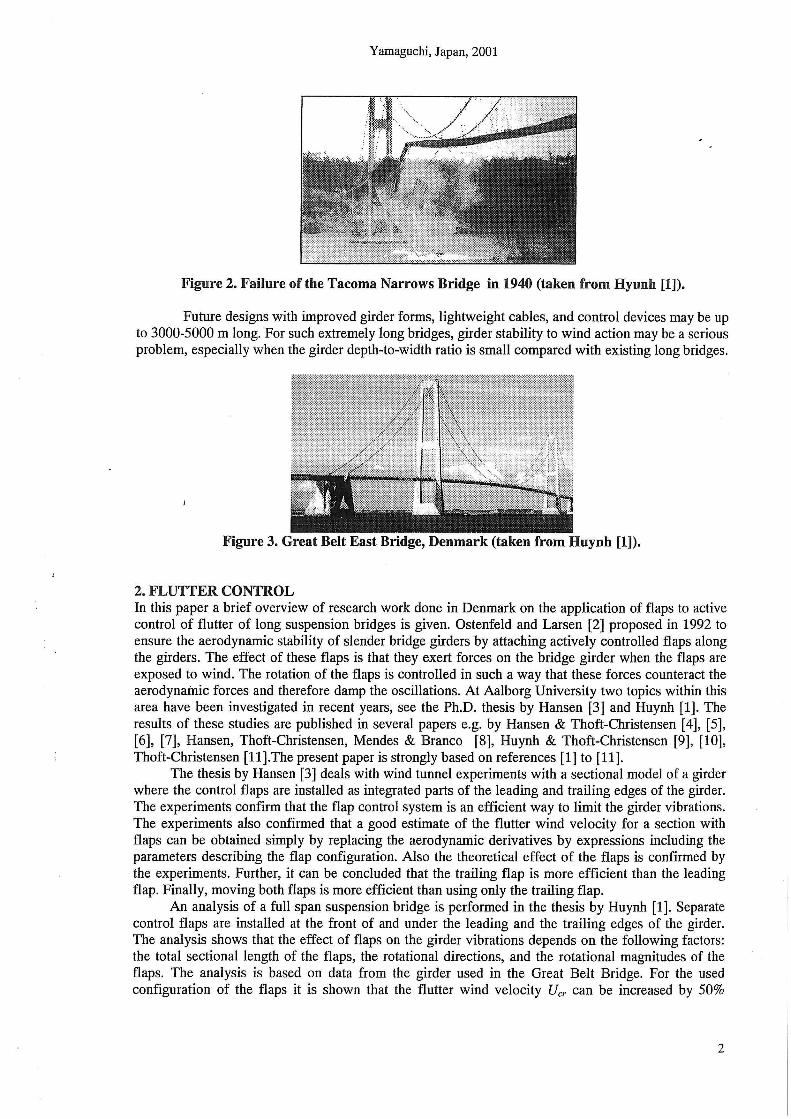
Figure 2. Failure of the Tacoma Narrows Bridge in 1940 (taken from Hyunh [1]).
Future designs with improved girder forms, lightweight cables, and control devices may be up to 3000-5000 m long. For such extremely long bridges, girder stability to wind action may be a serious problem, especially when the girder depth-to-width ratio is small compared with existing long bridges.
Figure 3. Great Belt East Bridge, Denmark (taken from Huynh [1]).
2. FLUTIER CONTROL In this paper a brief overview of research work done in Denmark on the application of flaps to active control of flutter of long suspension bridges is given. Ostenfeld and Larsen [2] proposed in 1992 to ensure the aerodynamic stability of slender bridge girders by attaching actively controlled flaps along the girders. The effect of these flaps is that they exert forces on the bridge girder when the flaps are exposed to wind. The rotation of the flaps is controlled in such a way that these forces counteract the aerodynamic forces and therefore damp the oscillations. At Aalborg University two topics within this area have been investigated in recent years, see the Ph.D. thesis by Hansen [3] and Huynh [1]. The results of these studies are published in several papers e.g. by Hansen & Thoft-Christensen [4], [5], [6], [7], Hansen, Thoft-Christensen, Mendes & Branco [8], Huynh & Thoft-Christensen [9], [10], Thoft-Christensen [ll].The present paper is strongly based on references [1] to [11].
The thesis by Hansen [3] deals with wind tunnel experiments with a sectional model of a girder where the control flaps are installed as integrated parts of the leading and trailing edges of the girder. The experiments confirm that the flap control system is an efficient way to limit the girder vibrations. The experiments also confirmed that a good estimate of the flutter wind velocity for a section with flaps can be obtained simply by replacing the aerodynamic derivatives by expressions including the parameters describing the flap configuration. Also the theoretical effect of the flaps is confirmed by the experiments. Further, it can be concluded that the trailing flap is more efficient than the leading flap. Finally, moving both flaps is more efficient than using only the trailing flap.
An analysis of a full span suspension bridge is performed in the thesis by Huynh [1]. Separate control flaps are installed at the front of and under the leading and the trailing edges of the girder. The analysis shows that the effect of flaps on the girder vibrations depends on the following factors: the total sectional length of the flaps, the rotational directions, and the rotational magnitudes of the flaps. The analysis is based on data from the girder used in the Great Belt Bridge. For the used configuration of the flaps it is shown that the flutter wind velocity Ucr can be increased by 50%
2

Yamaguchi, Japan, 2001
compared with a girder with no flaps. Not only the flutter response can be limited by the flap rotations, but also the buffeting response can be reduced in the mean square value. The flap rotations in turbulence conditions will change the angle of attack of the wind to the flaps so that the total buffeting . induced forces acting on the girder system are reduced. The stochastic buffeting responses can be derived by a conventional stochastic response analysis in modal coordinates, and in accordance with the wind load consisting of a stochastic buffeting term and an aeroelastic term.
Controlling the vibrations of civil engineering structures using active control systems has been used primarily to fulfil serviceability and comfort requirements. For such cases failure of the control system is not critical for the users of the structures or the structure itself. The situation is completely different with regard to controlling the safety of a long-span bridge using a control system. In such a case a passive control system is preferred.
3. WIND LOADS ON A SUSPENSION BRIDGE WITHOUT FLAPS The three most serious vibrations of a suspension bridge girder are
• Motion-induced vibrations • Buffeting-induced vibrations and • Vortex-induced vibrations.
The motion-induced wind loads (aeroelastic forces) depend directly on deformations and deformation velocities of the girder, see figure 4. The buffeting-induced wind loads are the fluctuating wind loads due to the turbulence of the wind .
.. o B
Vz(X,t)
rx(x,t)
z Figure 4. Motion-induced wind loads for a bridge without flaps.
By assuming potential flow theory, Theodorsen [12] has shown for thin airfoils in incompressible flow that the motion-induced vertical load Lae(x,t) and the motion-induced moment Mae(x,t) on the airfoil are linear in the theoretical displacement and the torsional angle and their first and second derivatives (see figure 4), where xis the coordinate in the direction of the bridge and t the time. Let y and z be the coordinates in the direction across the bridge and in the vertical direction. Scanlan and Tomko [13] introduced a similar formulation for bridges. The aeroelastic forces L deck and ~eck per unit span and for small rotations can then be written, see Similu & Scanlan [14]
(1)
3
Yamaguchi, Japan, 2001
where K=Bw /U is the non-dimensional reduced frequency, B is the girder width, U is the mean wind velocity, w is the bridge oscillating frequency (rad.) at the wind velocity U, and p is air density.
Ht (K) and At (K) (i =1,2,3,4) are non-dimensional aerodynamic derivatives which can be estimated
by wind tunnel experiments. The quantities rx, v z /U and B r x /U are non-dimensional, effective angles of attack.
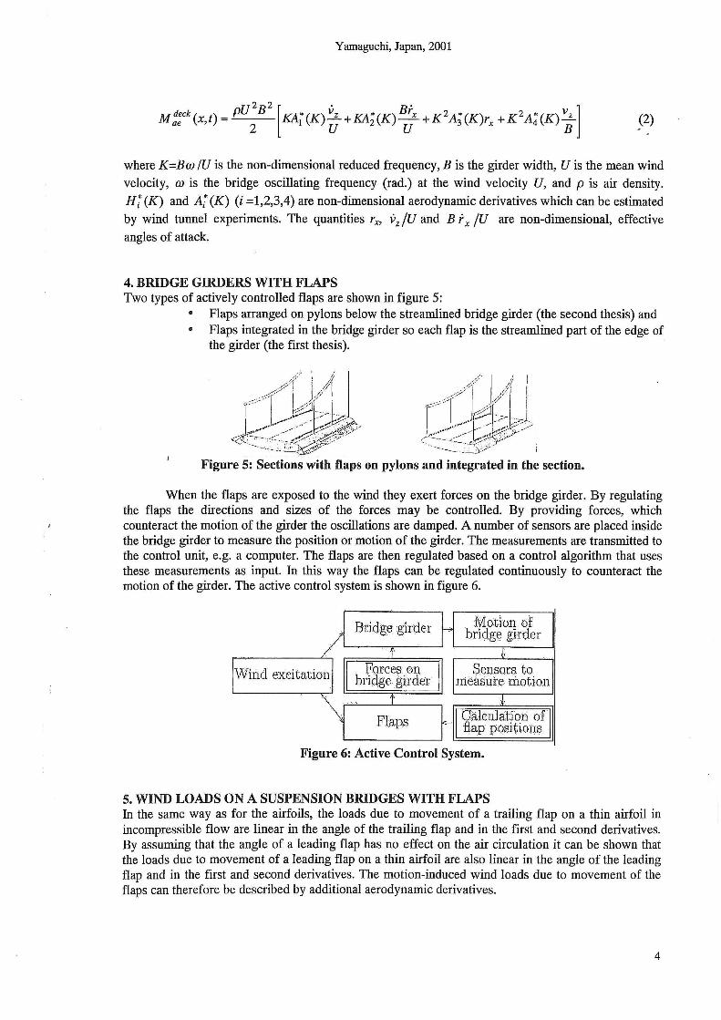
4. BRIDGE GIRDERS WITH FLAPS Two types of actively controlled flaps are shown in figure 5:
• Flaps arranged on pylons below the streamlined bridge girder (the second thesis) and • Flaps integrated in the bridge girder so each flap is the streamlined part of the edge of
the girder (the first thesis).
Figure 5: Sections with flaps on pylons and integrated in the section.
When the flaps are exposed to the wind they exert forces on the bridge girder. By regulating the flaps the directions and sizes of the forces may be controlled. By providing forces, which counteract the motion of the girder the oscillations are damped. A number of sensors are placed inside the bridge girder to measure the position or motion of the girder. The measurements are transmitted to the control unit, e.g. a computer. The flaps are then regulated based on a control algorithm that uses these measurements as input. In this way the flaps can be regulated continuously to counteract the motion of the girder. The active control system is shown in figure 6.
Bridge g. irdt3r Motion of __, bridge girder ~--------~'· ~--~,,.--~~ .~
Wind excitation 11 Forces on 11 btidge girder·
r Flaps
Sensors to. xneasute motwn
J
_11· C. a·l. cu. lat~qn·<.)f .. · f<:-11 fLap pqsxtwus
'-----------'
Figure 6: Active Control System.
5. WIND LOADS ON A SUSPENSION BRIDGES WITH FLAPS In the same way as for the airfoils, the loads due to movement of a trailing flap on a thin airfoil in incompressible flow are linear in the angle of the trailing flap and in the first and second derivatives. By assuming that the angle of a leading flap has no effect on the air circulation it can be shown that the loads due to movement of a leading flap on a thin airfoil are also linear in the angle of the leading flap and in the first and second derivatives. The motion-induced wind loads due to movement of the flaps can therefore be described by additional aerodynamic derivatives.
4

Yamaguchi, Japan, 2001
V
- · · · · ·~ y
rl~ - L~e X
r, £;;;;--
Figure 7: Motion-induced wind loads on the girder and on the n$1• The total motion-induced wind loads per unit span on the girder and the flaps are, see figure 7,
Ltota/ = L deck + Ltr (v tr ) + Lie (v le) z z z z' rx z z' rx
Mtotat =MDeck +Mtr(v rtr)+Mte(v rte)+fLtr(v rtr)-Lte(-v rle))B X X X Z' X X Z' X ~ Z ' X Z ' X 2
I
(3)
(4)
where vz(x,t) and rx(x,t) are the vertical motion and the rotation of the girder at position x along the
bridge girder at the timet. r;e (x,t) and r_: (x,t) are the rotations of the leading and the trailing flaps
as defined in figure 8.
Figure 8. Rotation of flaps.
6. THE THEOREICAL EFFECT OF FLAPS Figure 9 shows the calculated flutter velocity Ucr for different combinations of flap rotations. a is the
rotation of the girder, a1 and a1 are the rotations of the leading and the trailing flaps, CfJt and cp1 are the
phase angles between the leading flap, the trailing flap and the girder, respectively. The calculations show that the flutter wind velocity Ucr is increased when the phase angle for the leading flap q;1 is in
the interval [0.6Jr/6; 6.6nj6], otherwise the flutter wind velocity Ucr is reduced. The flutter wind
velocity Ucr for binary flutter is calculated for different values of amplification factor a1 and :1~:: for the
trailing flap. The calculations also show that the interval, where the flutter wind velocity is increased when the trailing flap is moved, is dependent on the flap a1• The flutter wind velocity is generally
reduced when the phase angle of the trailing flap Jl,i·. is in the interval [n/6; 6nj6]. For phase angles
outside this interval the flutter wind velocity is generally increased. The trailing flap is much more efficient than the leading flap.
5

15-
1:2
11
I 0-
Yamaguchi, Japan, 2001
a1 =at = a both flaps used
CfJ/ = ?m/6
rpt = &r:/6
fJJt = &r:/6
a1 =0
~ a1 =a
9 L=;;;;;;;;;;;;;;;~===--~- fJJ! = :m;6 at =0 8
~----,-------~--------~----~--~ a , 0.0 0 .7 0 . 4 0 .5 0 .8 1.0
only trailing flap used
only leading flap used
Figure 9: The theoretical effect on the flutter wind velocity of using flaps.
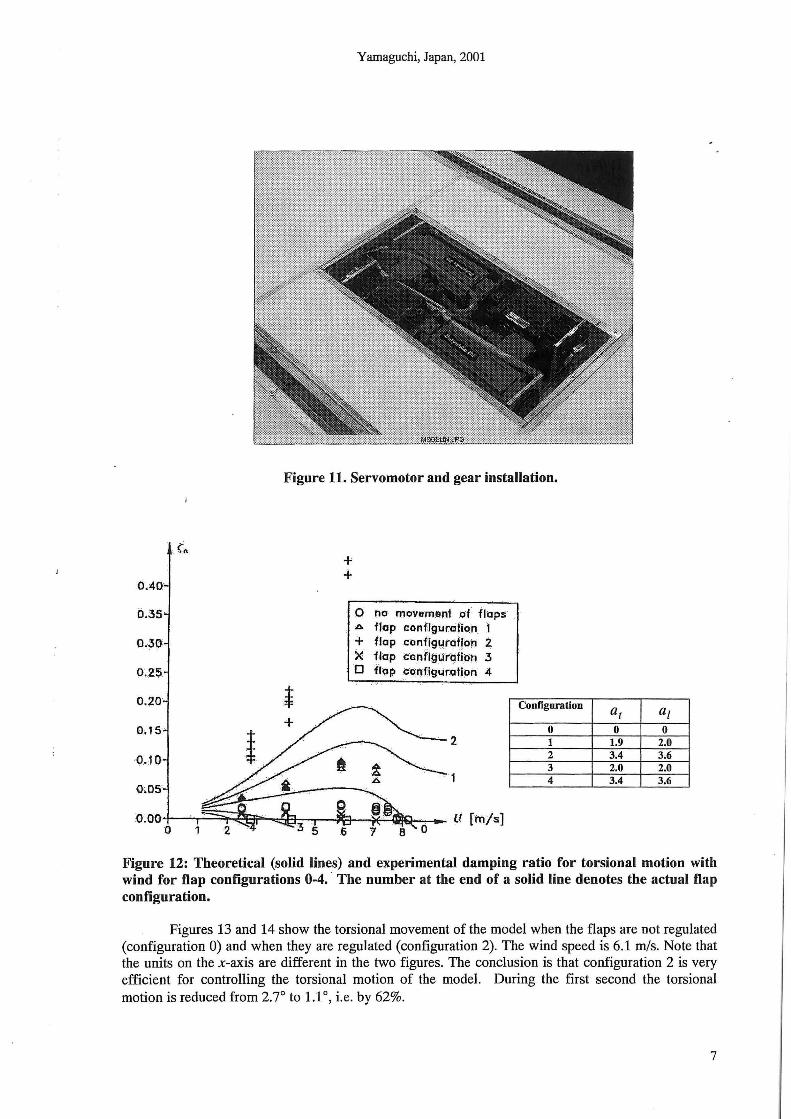
7. WIND TUNNEL TESTS Wind tunnel testing of a bridge section model has been performed in a wind tunnel at Instituto Superior Technico in Lisbon, Portugal. The bridge section model is shown in figure 10. The regulation system for moving the flaps consists of three parts: a servosystem, the regulation software to position the flaps, and the control software used to calculate the desired positions of the flaps. The servosystem consists of a servo-amplifier, a servomotor and a reduction gear. Two servosystems are used so that the two flaps can be regulated independently. The reduction gears and the servomotors are fixed inside the bridge section model. Each reduction gear is connected to the flaps via cables. Each servomotor is connected to a servo amplifier, which is placed outside the model. The servomotor and the gear installation are shown in figure 11.
Figure 10: Wind tunnel model.
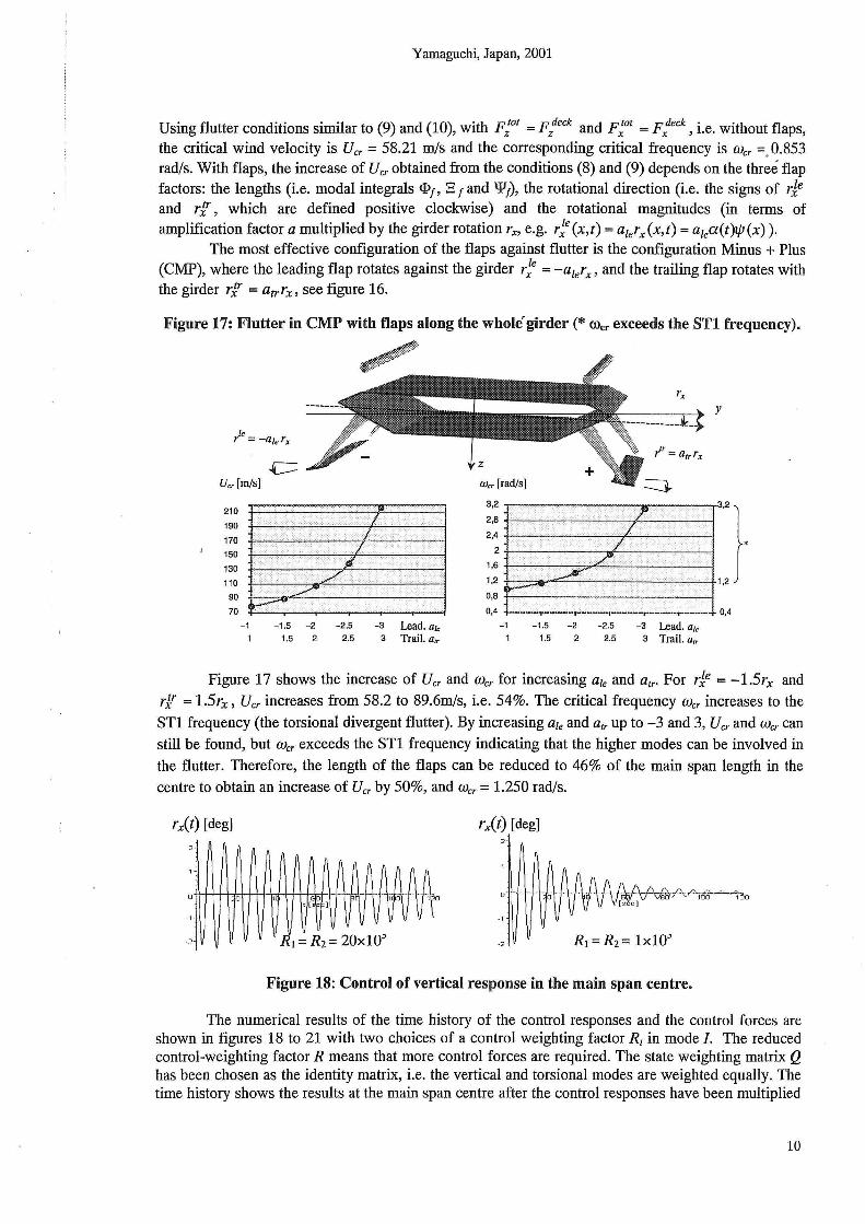
Several configurations of the flaps have been tested. As seen in figure 12, the experimental damping ratio is smaller for flap configurations 0 and 1 than the theoretical damping ratio, but the shape of the curve is almost the same. For flap configuration 2 the experimental damping ratio exceeds the theoretical one. For flap configurations 1 and 2, the theoretical curves show that no binary flutter will occur.
6
OAO
0.35
0.30 .
0.;25 ··
Yamaguchi, Japan, 2001
Figure 11. Servomotor and gear installation.
+ +
0 no movement of flops .o. flap conflguralioh 1 + flap conffg~,~t(lt{oh i X flap conflgtirgfion 3 D 'flop eor)fjgtir.otion 4
Configuration
0 1 2 3 4
at at 0 0
1.9 2.0 3.4 3.6 2.0 2.0 3.4 3.6
Figure 12: Theoretical (solid lines) and experimental damping ratio for torsional motion with wind for flap configurations 0-4. · The number at the end of a solid line denotes the actual flap configuration.
Figures 13 and 14 show the torsional movement of the model when the flaps are not regulated (configuration 0) and when they are regulated (configuration 2). The wind speed is 6.1 m/s. Note that the units on the x-axis are different in the two figures. The conclusion is that configuration 2 is very efficient for controlling the torsional motion of the model. During the first second the torsional motion is reduced from 2.7° to 1.1 °, i.e. by 62%.
7

Yamaguchi, Japan, 2001
n(t) J degJ
3
2
-.3
Figure 13: Torsional motion for flap configuration 0 and wind speed 6.1 m/s.
8. FLUTTER CONDITIONS
n(tl I c~.,.g I
-3
Figure 14: Torsional motion for flap configuration 2 and wind speed 6.1 m/s.
Let f/J;(x) and 1.pj{x) be the vertical and the torsional mode shapes of the bridge in mode i and mode j which ~re assumed to be coupled at flutter. The governing modal equations for the two-mode flutter conditions are then
M z ( z(t) + 2w/; zz(t) + w;z(t) )= FJ01 (t)
M x ( ii(t) + 2wa'aa(t) + w~a(t) )= F1°1 (t)
(5)
(6)
where z(t) and a(t) are the vertical and the torsional modal coordinates. Wz, {;z and Wa and {;a are the natural frequencies and the damping ratios of the vertical and torsional modes. Mz and Mx are the vertical and the torsional modal masses. At the coupled motion, the vertical and the torsional modal responses are both assumed to be proportional to eiw t , when the critical wind velocity is acting on the
bridge, i.e. z(t) = zoeiwt and a(t) = aoeiwt. When this is introduced into the above equations the following matrix equation can be derived
(7)
where the system matrix A depends on the natural mode shapes and frequencies, the damping ratios, the derivatives and the wind velocity. This matrix equation has non-trivial solutions when
Det(A) =Re Det(A) + i Im Det(A) = 0 (8)
resulting in the following two flutter conditions for a bridge with separate flaps, Huynh [1]:
(9)
8

Yamaguchi, Japan, 2001
Im(Det) = w:( M 2 +_Q__+ 31 [LlM3+L4M2-MlL3-M4L2]J
w z I w 1J1 mw Cf> mw Cf>J1JI J
+w2
(_,.,,_ _,.,,_ Wa_,.,,_ Wa~_,.,,_ M3) 2 ~z ~a ~a 2 ~z 2
Wz Wz Wz mw Cf> Jw 1J1
+ ~(- M2 _ w~ ___Q_) + 2{; w~ + ~ Wa = 0 (10) Wz Jw1JI w'l mwct> z w'l a Wz
where m is the girder mass per unit span. <P, E and Ware the modal integrals of the girder given by: L L L
<P = Jt/>((x)dx, E = J4>1(x)!Jlt(x)dx, and W =f'IJl{(x)dx (11) 0 0 0
and where Ll to L4 and M 1 to M 4 contain the modal integrals of the flaps <P1, E 1 and 'PI> the sum of flutter derivatives referred to the girder and the flaps (see Huynh [1] for full expressions). Finally, note that the flutter mode can be a coupling of more than two modes. In that case, an additional mode gives an additional equation. The determinant condition (8) is still valid, but the calculation of the solution is rather complicated analytically. Generally, the obtained critical wind velocity Ucr and the critical frequency Wcr will not be varied by more than 5%, if several similar mode shapes with close frequencies are taken- into account in the flutter computation, see Huynh, [ 1].
9.EXAMPLE In this section the theory presented above is illustrated by an example taken from Huynh [1]. The suspension bridge shown in figure 15 is considered. It has a streamlined cross-section similar to the cross-section,of the Great Belt Bridge. The cable sag is 265 m, the pylon top is 360 m, the girder depth is 4 m, and the girder cross-sectional area is 1.056 m2
• Applying both FEM and analytical calculation the 1st symmetrical vertical and torsional modes (SV1 and ST1) are 0.404 rad/s and 1.276 rad/s, respectively, see figure 16.
1000 m 2500 m 1000 m ~ I I 1
Figure 15: Suspension bridge used in the example.
Figure 16. The first symmetrical vertical bending mode (SV1) and the first symmetrical torsional mode of the bridge (ST1).
9
Yamaguchi, Japan, 2001
Using flutter conditions similar to (9) and (10), with F;ot = F/eck and F:01 = F1eck, i.e. without flaps, the critical wind velocity is Ucr = 58.21 m/s and the corresponding critical frequency is Wcr =. 0.853 rad/s. With flaps, the increase of Ucr obtained from the conditions (8) and (9) depends on the three flap factors: the lengths (i.e. modal integrals <1>1, E 1 and '¥1), the rotational direction (i.e. the signs of rje and rf, which are defined positive clockwise) and the rotational magnitudes (in terms of amplification factor a multiplied by the girder rotation rx, e.g. ,.;e(x,t) = a1erx(x,t) = a1ea(t)lp(x) ).
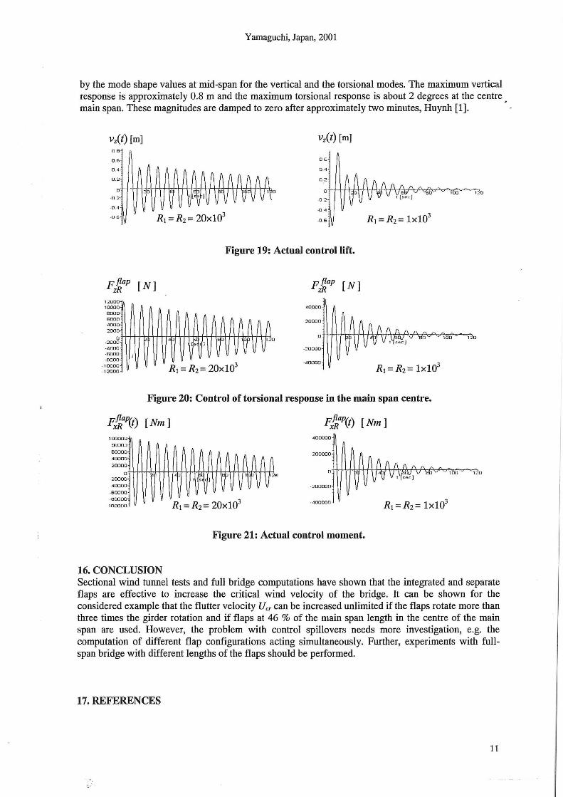
The most effective configuration of the flaps against flutter is the configuration Minus + Plus (CMP), where the leading flap rotates against the girder r;e = -a1erx , and the trailing flap rotates with the girder rf = atrrx, see figure 16.
Figure 17: Flutter in CMP with flaps along the whole girder(* rocr exceeds the STl frequency).
Ucr [rn/s]
210
190
170
150
130
110
90
70
-1
..c::::
-1.5 -2 -2.5 - 3 Lead. a le
1.5 2 2.5 3 Trai I. arr
y
Wcr [rad/s]
;:: :+ ,...-.:=_ .,...::':-" ....,==':-" ...,.==--,...,==~~==":-' "";=.';~!-~~:~r-:: __ .,..,==~ 7"=: : =-'-· ·· .. : __ .. •• -:.:...j .• 3,2}
: : * 2 ~~~~----~~~~7-~~1
1,6 · .. ·.
1,2 .· .. 1,2
o,a r ·· ~'-"-'~~~:....,__.....;;_..,.-~--;,...·· '-1
-----~·~:~T--·-~----~--~--~ --·- .~·--~· .. ~.:~:T··-~--L~ . .;. ... : ~ ~~.-- 0,4 0,4
-1
1
-1.5 1.5
-2
2 -2.5
2.5 -3 Lead. a1c
3 Trail. a,,
Figure 17 shows the increase of Ucr and Wcr for increasing ale and a1,. For rje = -l.51:X and rf = l.51:X, Ucr increases from 58.2 to 89.6m/s, i.e. 54%. The critical frequency Wcr increases to the
ST1 frequency (the torsional divergent flutter). By increasing ale and atr up to -3 and 3, Ucr and Wcr can still be found, but Wcr exceeds the STl frequency indicating that the higher modes can be involved in
the flutter. Therefore, the length of the flaps can be reduced to 46% of the main span length in the
centre to obtain an increase of Ucr by 50%, and Wcr = 1.250 rad/s.
rx(t) [deg]
/'AftAAA A - ~-H+t-t-t*H_ o H-+-bH, -++,~[. o-++J V +--1;-;tv v+t--IJH;-;t;~,oo;\-H\1 VH-*-1'\
-2 R1 = Rz= 20x10~
rx(t) [deg]
-2
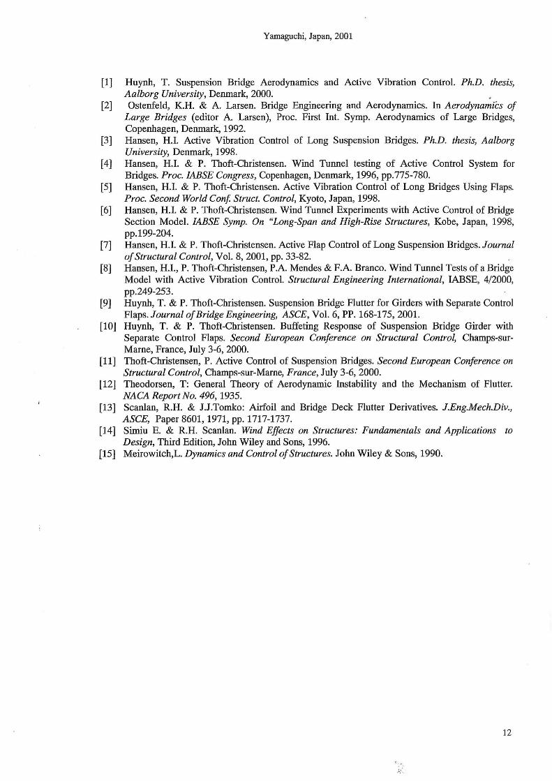
Figure 18: Control of vertical response in the main span centre.
The numerical results of the time history of the control responses and the control forces are shown in figures 18 to 21 with two choices of a control weighting factor Ri in mode /. The reduced control-weighting factor R means that more control forces are required. The state weighting matrix Q has been chosen as the identity matrix, i.e. the vertical and torsional modes are weighted equally. The time history shows the results at the main span centre after the control responses have been multiplied
10
Yamaguchi, Japan, 2001
by the mode shape values at mid-span for the vertical and the torsional modes. The maximum vertical response is approximately 0.8 m and the maximum torsional response is about 2 degrees at the centre main span. These magnitudes are damped to zero after approximately two minutes, Huynh [1]. ·
vz(t) [m] 08
0 .6·
0 .4
0 .2
o++++r-H~~rh~~+r~-rr++.QH~~
-0 :?
-0 .11
·0 6
vz(t) [m]
DE>
0 4
Figure 19: Actual control lift.
pflap zR (N] F~ap [N]
1:::20 00 10 0 0 0 40000·
BODO GOOD 4000 2 0 00
0 ·20 00 -4000 -6000 I -800 (1
-1 0000 -40000 ·
- 12000
Figure 20: Control of torsional response in the main span centre.
100000
8 0000
~~~~~ AnAAA/\ 20000 11 /I 1\
o+++-1-+t.:H,, -t+t-!d--t-t+l::!rH-H±pH-+ vV+:hl, VJP~' V t+:lv-til ·20000 t s ]
40000
-6 0000
-BtJOOO 3 1omr"' R1 = Rz = 20x10
40 0 000
Figure 21: Actual control moment.
16. CONCLUSION Sectional wind tunnel tests and full bridge computations have shown that the integrated and separate flaps are effective to increase the critical wind velocity of the bridge. It can be shown for the considered example that the flutter velocity Ucr can be increased unlimited if the flaps rotate more than three times the girder rotation and if flaps at 46 % of the main span length in the centre of the main span are used. However, the problem with control spillovers needs more investigation, e.g. the computation of different flap configurations acting simultaneously. Further, experiments with fullspan bridge with different lengths of the flaps should be performed.
17. REFERENCES
11
Yamaguchi, Japan, 2001
[1] Huynh, T. Suspension Bridge Aerodynamics and Active Vibration Control. Ph.D. thesis, Aalborg University, Denmark, 2000. .
[2] Ostenfeld, K.H. & A. Larsen. Bridge Engineering and Aerodynamics. In Aerodynamics of Large Bridges (editor A. Larsen), Proc. First Int. Symp. Aerodynamics of Large Bridges, Copenhagen, Denmark, 1992.
[3] Hansen, H.l. Active Vibration Control of Long Suspension Bridges. Ph.D. thesis, Aalborg University, Denmark, 1998.
[4] Hansen, H.l. & P. Thoft-Christensen. Wind Tunnel testing of Active Control System for Bridges. Proc. IABSE Congress, Copenhagen, Denmark, 1996, pp.775-780.
[5] Hansen, H.l. & P. Thoft-Christensen. Active Vibration Control of Long Bridges Using Flaps. Proc. Second World Conf. Struct. Control, Kyoto, Japan, 1998.
[6] Hansen, H.l. & P. Thoft-Christensen. Wind Tunnel Experiments with Active Control of Bridge Section Model. IABSE Symp. On "Long-Span and High-Rise Structures, Kobe, Japan, 1998, pp.199-204.
[7] Hansen, H.l. & P. Thoft-Christensen. Active Flap Control of Long Suspension Bridges. Journal of Structural Control, Vol. 8, 2001, pp. 33-82.
[8] Hansen, H.l., P. Thoft-Christensen, P.A. Mendes & F.A. Branco. Wind Tunnel Tests of a Bridge Model with Active Vibration Control. Structural Engineering International, IABSE, 4/2000, pp.249-253.
[9] Huynh, T. & P. Thoft-Christensen. Suspension Bridge Flutter for Girders with Separate Control Flaps. Journal of Bridge Engineering, ASCE, Vol. 6, PP. 168-175, 2001.
[10] Huynh, T. & P. Thoft-Christensen. Buffeting Response of Suspension Bridge Girder with Separate Control Flaps. Second European Conference on Structural Control, Champs-surMame, France, July 3-6, 2000.
[11] Thoft-Christensen, P. Active Control of Suspension Bridges. Second European Conference on Structural Control, Champs-sur-Mame, France, July 3-6, 2000.
[12] Theodorsen, T: General Theory of Aerodynamic Instability and the Mechanism of Flutter. NACA Report No. 496, 1935.
[13] Scanlan, R.H. & J.J.Tomko: Airfoil and Bridge Deck Flutter Derivatives. J.Eng.Mech.Div., ASCE, Paper 8601, 1971, pp. 1717-1737.
[14] Simiu E. & R.H. Scanlan. Wind Effects on Structures: Fundamentals and Applications to Design, Third Edition, John Wiley and Sons, 1996.
[15] Meirowitch,L. Dynamics and Control of Structures. John Wiley & Sons, 1990.
12
. . -~.' ..


STRUCTURAL RELIABILITY THEORY SERIES Redcent papers
PAPER NO. 218E: S0rensen, J.D., Faber, M.H.: Generic Inspection Planning for Steel Structures.
PAPER NO. 217: S0rensen, J.D. ; Faber, M.H.: Simplified, Generic Inspection Planning for Steel Structures.
PAPER NO. 216: S0rensen, J.D.; Faber, M.H.: Reliab>ility-Based Optimal Planning of Maintenance and Inspection.
PAPER NO. 215: S0rensen, J.D. ; Faber, M.H. : Codified Risk Based Inspection Planning.
PAPER NO. 214E: S0rensen, J.D . ; Sterndorff, M.: Stochastic Model for Loads on Offshore Structures from Wave, Wind, Current and Water Elevation.
PAPER NO. 213E: S0rensen, J.D.; Hansen, J.O.; Nielsen, T.A.: Calibration of Partial Safety Factors and Target Reliability Level in Danish Structural Codes.
PAPER NO. 212: Sterndorff, M .. ; S0rensen, J.D.: A Rational Procedure for Determination of Directional Individual Design Wave Heights.
PAPER NO. 211: Lassen, T.; S0rensen, J.D.: A Probabilistic Damage Tolerance Concept for Welded Joints, Part 2.
PAPER NO. 210: Lassen, T.; S0rensen, J.D.: A Probabilistic Damage Tolerance Concept ftx Welded Joints, Part 1.
PAPER NO. 209: Faber, M.H.; S0rensen, J.D.: Bayesian Sampling Using Condition Indicators.
PAPER NO. 208E: Faber, M.H.; S0rensen, J.D.: Indicators for Assessment and Inspection Planning.
PAPER NO. 207: Faber, M.H.; S0rensen, J.D.: Indicators for Inspection and Maintenance Planning of Concrete Structures.
PAPER NO. 206P-E: J.D. S0rensen; P. Hoffmeyer: Statistical Analysis of Data for Timber Strengths. ISSN 1395-7953 R0132
PAPER NO. 205: Chr. Frier: Stochastic Finite Element Method for Materials Modelled by Nonlinear Plasticity Theory. Ph.D. Thesis. ISSN 1395-7953 R0131 .
PAPER NO. 204P-E: P. Thoft-Christensen: Deterioration of Concrete Structures. ISSN 1395-7953 RO 130.
'
PAPER NO. 203P·E: P. Thoft-Christensen: Improving the Dynamics of Suspension Bridges using Active Control Systems. ISSN 1395-7953 R0117.
P =Paper version E =Electronic version, see address below
A full list of papers can be seen from http://www.civil.auc.dkli6/publ/srlist.html

ISSN 1395-7953 R0117
Dept. of Building Technology and Structural Engineering
Aalborg University, September 2001
Sohngaardsholmsvej 57, DK-9000 Aalborg , Denmark
Phone: +45 9635 8080 Fax: +45 9814 8243
www.civil.auc.dk/i6