aalborg universitet design procedure for hybrid ... · the first ideas on a design procedure for...
TRANSCRIPT

Aalborg Universitet
Design Procedure for Hybrid Ventilation
Heiselberg, Per; Tjelflaat, Per Olaf
Publication date:1999
Document VersionPublisher's PDF, also known as Version of record
Link to publication from Aalborg University
Citation for published version (APA):Heiselberg, P., & Tjelflaat, P. O. (1999). Design Procedure for Hybrid Ventilation. Dept. of Building Technologyand Structural Engineering, Aalborg University. Indoor Environmental Engineering, No. 104, Vol.. R9941
General rightsCopyright and moral rights for the publications made accessible in the public portal are retained by the authors and/or other copyright ownersand it is a condition of accessing publications that users recognise and abide by the legal requirements associated with these rights.
? Users may download and print one copy of any publication from the public portal for the purpose of private study or research. ? You may not further distribute the material or use it for any profit-making activity or commercial gain ? You may freely distribute the URL identifying the publication in the public portal ?
Take down policyIf you believe that this document breaches copyright please contact us at [email protected] providing details, and we will remove access tothe work immediately and investigate your claim.
Downloaded from vbn.aau.dk on: July 16, 2020

Pap
er
No
104
Indo
or
En
viro
nme
ntal
Eng
_inee
rin
g
Pre
sent
ed a
t th
e F
irst
Int
ern
atio
nal
On
e D
ay F
oru
m o
n
Na
tura
l and
Hyb
rid V
ent
ilatio
n. H
ybV
ent
Fo
rum
'99
.
Sid
ney
. A
ust
ralia
. Se
pte
mb
er
1999
lJ
:J::
(]) (lj•
.\ (]
) c (]) ea .. lJ
(]) .... 0 --Q) -....
..::-! ~ ~
Q)
Q)
I 0
'<
CD
rr
(/)
:::!.
-·
CO
0..
::::
:J
~
"1J
......
:::::J
0 ...
..-+
0 -·
-
CD
Q)
.....-
+ 0
..
0 c .....
. :::::
J CD
---
+-!
0 ......

The Indoor Environmental Engineering papers are issued for early dissemination of research results from the Indoor Environmental Engineering Group at the Department of Building Technology and Structural Engineering , Aalborg University. These papers are generally submitted to scientific meetings, conferences or journals and should therefore not be widely distributed. Whenever possible , reference should be given to the final publications (proceedings , journals , etc.) and not to the Indoor Environmental Engineering papers.
Printed atAalborg University

Design Procedure for
Hybrid Ventilation
P Heiselberg, Per 0/af Tjelflaat


DESIGN PROCEDURE FOR HYBRID VENTILATION
ABSTRACT
Per Heiselberg Indoor Environmental Engineering
Aalborg University Sohngaardsholmsvej 57, DK-9000 Aalborg, Denmark
tax: +45 9814 8243 e-mail: ph@ civil.auc.dk
Per Olaf Tjelflaat Dep. of Refrigeration and Air Conditioning
Norwegian University of Science & Technology Kolbjoern Hejes Vei 1 b, N-7034 Trondheim, Norway
tax: +4 7 73 593 859 e-mail: per.o.tjelflaat@ kkt.ntnu.no
Mechanical and natural ventilation systems have developed separately during many years. The natural next step in this development is development of ventilation concepts that utilises and combines the best features from each system into a new type of ventilation system - Hybrid Ventilation.
Buildings with hybrid ventilation often include other sustainable technologies and an energy optimisation requires an integrated approach in the design of the building and its mechanical systems. Therefore, the hybrid ventilation design procedure differs from the design.procedure for conventional HVAC. The first ideas on a design procedure for hybrid ventilation is presented and the different types of design methods, that is needed in different phases of the design process, is discussed.
1 INTRODUCTION
Mechanical and natural ventilation systems have developed separately during many years. Mechanical ventilation has developed from constant air flow systems through systems with extensive heat recovery and demand controlled air flows to energyoptimised low pressure ventilation systems. Natural ventilation has in the same period developed from being considered only as air infiltration through cracks and airing through windows to be a demand controlled ventilation system with cooling capabilities and heat recovery and air cleaning possibilities. The focus in the development has for both systems been to minimise energy consumption while maintaining a comfortable and healthy indoor environment. The natural next step in this development is to develop ventilation concepts that utilises and combines the best features from each system into a new type of ventilation system- Hybrid Ventilation.
Hybrid ventilation systems can be described as systems providing a comfortable internal environment using different features of both natural ventilation and mechanical systems at different times of the day or season of the year.

Hybrid Ventilation Concepts t
Heat recovery Demand controlled Air cleaning .. .. natural ventilation
t t Selfregulating supply and
exhaust grills
t Openable windows
Supply and exhaust grills
Air infiltration through cracks
Natural Ven tilation
t Low pressure
mechanical ventilation
t Demand controlled
ventilation
t Constant air flow
mechanical ventilation
Mechanical Ventilation Figure 1 Development of natural and mechanical ventilation systems (Wouters 1999).
lt is a ventilation system where mechanical and natural forces are combined in a twomode system. The basic philosophy is to maintain a satisfactory indoor environment by alternating between and combining these two modes to avoid the cost, the energy penalty and the consequential environmental effects of year-round air conditioning. The operating mode varies according to the season and within individual days, thus the current mode reflects the external environment and takes maximum advantage of ambient conditions at any point in time. The main difference between conventional ventilation systems and hybrid systems is the fact that the latter are intelligent with control systems that automatically can switch between natural and mechanical mode in order to minimise the energy consumption.
Hybrid ventilation should dependent on building design, internal loads, natural driving forces, outdoor conditions and season fulfil the immediate demands to the indoor environment in the most energy-efficient manner. The control strategies for hybrid ventilation systems should maximise the use of ambient energy with an effective balance between the use of advanced automatic control and the opportunity for users of the building to exercise direct control of their environment. The control strategies should also establish the desired air flow rates and air flow patterns at the lowest energy consumption possible.
2 INTEGRATED AND CLIMATIC DESIGN
Buildings with hybrid ventilation often include other sustainable technologies like daylightning, passive cooling, passive solar heating etc, and an energy optimisation requires an integrated approach in the design of the building and its mechanical systems.
Today, the construction industry is in the early stages of reinventing the design process that was used before the advent of mechanical systems. Design teams including both architects and engineers are formed and the building design is developed in an iterative
2

process from the conceptual design ideas to the final detailed design. Building energy use and HVAC equipment sizes are reduced without the use of sophisticated technologies, but only through an effective integration of the architectural and HVAC designs. The integrated design approach achieves this improved energy utilisation due to the relationship that exists between the building, its surroundings and architecture and the mechanical systems. In the integrated design process the expertise of the engineer is available from the very beginning at the conceptual design stage and the optimisation of the architectural and HVAC designs can start at the same time as the first design ideas are developed.
The art and science of using the beneficial elements of nature- sun, wind, earth and air temperature, plants and moisture - to create comfortable, energy-efficient and environmentally wise buildings is called climatic design. The desirable procedure is to work with, not against, the forces of nature and to make use of their potentialities to create better living conditions. The principles of climatic design derive from the requirement for creating human comfort in buildings using the elements of the natural climate. Perfect balance between natural resources and comfort requirements can scarcely be achieved except under exceptional environmental circumstances and the climatic design will vary throughout the year depending upon whether the prevailing climatic condition is "underheated" compared to what is required for comfort (i.e., like winter) or" overheated" (i.e., like summer).
The integrated design of the heating, cooling, lighting and ventilation of buildings can be accomplished in three separate steps. The first step is the design of the building itself to minimise heat loss and maximise heat gain in winter, to minimise heat gain in summer, and to use daylight and fresh air efficiently. Decisions at this step determine the size of the heating, cooling and lighting loads. Poor decisions at this point can easily double or triple the size of the mechanical equipment eventually needed. The second step involves the climatic design where the passive heating, passive cooling, daylighting techniques and natural ventilation heat the building in the winter, cool it in the summer and light and ventilate it all year. The proper decisions at this point can greatly reduce the loads as they were created during the first step. Step 3 consists of designing the mechanical equipment to handle the loads that remain from the combined effect of steps 1 and 2, see figure 2.
Heating Cooling Step 1 Conservation Heat avoidance
Basic Design 1. Surface to volume 1. Shading ratio 2. Exterior
2. Insulation colours 3. Infiltration 3. Insulation
Step 2 Passive solar Passive coo/ins
Climatic design 1. Direct gain l. Evaporative 2. Thermal storage cooling
wall 2. Convective 3. Sunspace cooling
3. Radiant cooling
Step3 Heating system Cooling system
Design of Mechanical 1. Radiators I. Refrigeration Systems 2. Radiant panels machine
3. Warm air system 2. Cooled ceiling 3. Cold air system
Lighting Davlisht
1. Windows 2. Glazing 3. Interior finishes
Daylishtins
l. Skylights 2. Light shelves 3. Light wells
Electric light
I. Lamps 2. Fixtures 3. Location of
fixtures
Ventilation Natllral ventilation
1. Building form 2. Location of
windows and openings
3. Stacks Natural ventilation
I. Wind induced ventilation
2. Bouyancy induced ventilation
3. Air distribution 4. Control system Mechanical ventilation
I. Mechanical exhaust
2. Mechanical ventilation
3. Air conditioning
Figure 2 Typical design considerations at each design step. Revised from (Lechner 1991).
3

The heating, cooling, lighting and ventilation design of buildings always involves all three steps whether consciously considered or not. Minimal demands have in the recent past been placed on the building itself to affect the indoor environment. lt was assumed that it was primarily the engineers at the third step which were responsible for the environmental control of the building. Thus architects, who were often indifferent to the heating and cooling needs of buildings, sometimes designed buildings with large glazed areas for very hot or very cold climates, and the engineers would then be forced to design giant heating and cooling plants to maintain thermal comfort. On the other hand, when it is consciously recognised that each of these steps is an integral part of the heating, cooling, lighting and ventilation design, better buildings result. The buildings are better for several reasons. They are often less expensive because of reduced mechanical equipment and energy needs. Frequently they are also more comfortable because the mechanical equipment does not have to fight giant loads.
3 HYBRID VENTILATION DESIGN PROCEDURE
The hybrid ventilation proc~ss is very dependent on the outdoor climate, the microclimate around the building as well as the thermal behaviour of the building and it is, therefore, essential that these factors are taken into consideration in the basic design step. The output from the first step is a building orientation, -design and -plan that minimises the thermal loads on the building in overheated periods, that together with the selected ventilation strategy makes it possible to exploit the dominating driving forces (wind and/or buoyancy) ;at the specific location and that ensures a proper air distribution through the building. lt is also important that issues like night cooling potential, noise and air pollution in the surroundings as well as fire safety and security are taken into consideration.
In the climatic design step the natural ventilation mode of the hybrid system is designed. The location and size of openings in the building as well as features to enhance the driving forces as solar chimneys and thermal stacks are designed according to the selected strategy for both day and night time ventilation. Passive methods to heat and/or cool the outdoor air is considered as well as heat recovery and filtering. Appropriate control strategies for the natural ventilation mode are determined and decisions are made regarding the level of automatic and/or manual control and user interaction.
In step three the necessary mechanical systems to fulfil the comfort and energy requirements are designed. These can range from simple mechanical exhaust fans to enhance the driving forces to balanced mechanical ventilation or air conditioning systems. The hybrid ventilation and corresponding whole system control strategy are determined to optimise the energy consumption while maintaining acceptable comfort conditions.
Effective and efficient climatization and ventilation of indoor spaces has the best chance for success when the design process is carried out in a logical, subsequent manner with increasing detail richness towards final design, and in the framework of a design procedure. In the case of hybrid ventilation the need for a design procedure is even more evident due to the comprehensive design team, where users, building owner, architect, civil engineer and indoor climate and energy counsellor must all be involved -simultaneously.
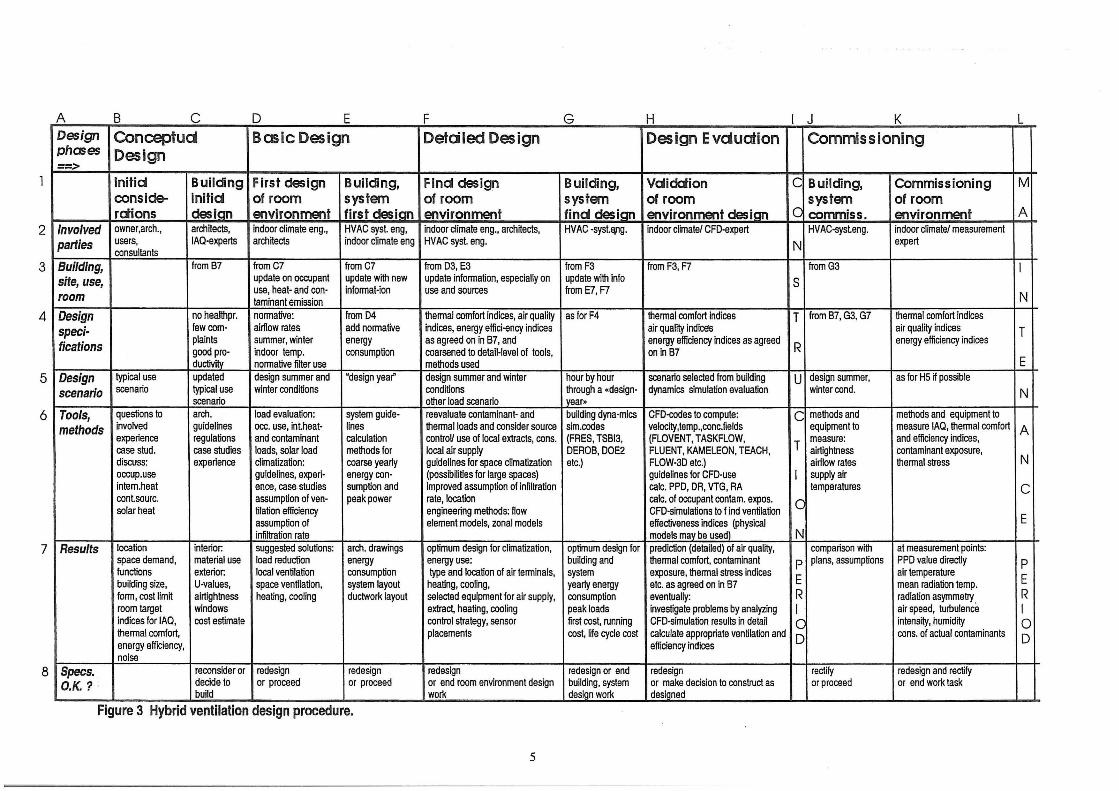
A HVAC design procedure consists of different phases: conceptual design phase, basic design phase, detailed design phase and design evaluation, see figure 3.
4
A B c D E F G H J K L Design Conceptud Basic Design Detdled Design Design Evduation Commissioning phases Design ==>
lnitid Building First design Building, Find design Building, Vdidction c Building, Commissioning M conside- initid of room system of room system of room system of room rdions desian environment first desian environment find desian environment desian _C: commiss. environment A
2 Involved owner,arch., architects, indoor climate en g., HVAC syst. eng, indoor climate eng., architects, HVAC -syst.EVJg. indoor climate/ CFD-expert HVAC-systeng. indoor climate/ measurement
parties users, IAQ·experts architects indoor climate eng HVAC syst. eng. N expert consultants
Building, fromB7 fromC7 fromC7 from 03, E3 from F3 from F3, F7 from G3 I site, use, update on occupant update with new update information, especially on update with into s use, heat· and con· informat-ion use and sources from E7, F7
N room taminant emission
3
Design no healthpr. normative: fromD4 thermal comfort indices, air quality asforF4 thermal comfort Indices T from B7, G3, G7 thermal comfort indices
speci- few cam· airflow rates add normative indices, energy effici-ency indices air quality indices air quality indices T fications plaints summer, winter energy as agreed on in B7, and energy efficiency indices as agreed
R energy efficiency indices
good pro· indoor temp. consumption coarsened to detail-level of tools, on in 87 ductivity normative filter use methods used E
4
Design typical use updated design summer and "design year" design summer and winter hour by hour scenario selected from building U design summer, as for HS if possible
scenario scenario typical use winter conditions conditions through a •design- dynamics simulation evaluation winter cond. N scenario other load scenario year•
5
Tools, questions to arch. load evaluation: system guide· reevaluate contaminant· and building dyna-mics CFD-codes to compute: C methods and methods and equipment to
methods involved guidelines ace. use, intheat· lines thermal loads and consider source sim.codes velocity,temp.,conc.fields equipment to measure IAQ, thermal comfort A experience regulations and contaminant calculation controV use of local extracts, cons. (FRES, TSBI3, (FLOVENT, TASKFLOW,
T measure: and efficiency indices,
case stud. case studies loads, solar load methods for local air supply DEROB, DOE2 FLUENT, KAMELEON, TEACH, airtightness contaminant exposure, I
discuss: experience climatization: coarse yearly guidelines for space climatization etc.) FLOW-3D etc.) airflow rates thermal stress N
6
occup.use guidelines, experi· energy con· (possibilities for large spaces) guidelines for CFD-use I supply air intem.heat ence, case studies sumption and improved assumption of infiltration calc. PPD, DR, VTG, RA temperatures c cont.sourc. assumption of ven- peak power rate, location calc. of occupant contam. expos. c solar heat tilation efficiency engineering methods: flow CFD·simulations to I ind ventilation
assumption of element models, zonal models effectiveness indices (physical E infiltration rate models may be used) N
7 Results location interior: suggested solutions: arch. drawings optimum design for climatization, optimum design for prediction (detailed) of air quality, comparison with at measurement points: space demand, material use load reduction energy energy use: building and thermal comfort, contaminant p plans, assumptions PPD value directly p !unctions exterior: local ventilation consumption type and location of air terminals, system exposure, thermal stress indices
E air temperature
E building size, U-values, space ventilation, system layout heating, cooling, yearly energy etc. as agreed on in B7 mean radiation temp. form, cost limit airtightness healing, cooling ductwork layout selected equipment for air supply, consumption eventually: R radiation asymmetry. R room target windows extract, heating, cooling peak loads investigate problems by analyzing I air speed, turbulence I indices for IAQ, cost estimate control strategy, sensor first cost, running CFD·simulation results in detail 0 intensity, humidity 0 thermal comfort, placements cost, life cycle cost calculate appropriate ventilation and D cons. of actual contaminants D energy efficiency, efficiency indices noise
8 Specs. reconsider or redesign redesign redesign redesign or end redesign rectify redesign and rectify O.K.? , decide to or proceed or proceed or end room environment design building, system or make decision to construct as or proceed or end work task
build work design work designed
Figure 3 Hybrid ventilation design procedure.
5

The conceptual design phase includes decisions on building form, size, function and location. Targets are set for indoor air quality, thermal comfort and energy use as well as cost limits. The conceptual design of the hybrid ventilation system is based on these considerations, guidelines and experiences from previous buildings. The natural ventilation principle (stack and/or wind driven, single sided and/or cross ventilation) to be used is decided together with the principle of the necessary additional mechanical systems.
In the basic design phase the building heat, sun and contaminant loads are estimated and the hybrid ventilation system layout designed. The necessary air flow rates as well as expected indoor air quality and temperature levels are calculated. A coarse yearly energy consumption is calculated together with the necessary peak power demands. If the results do not meet the targets, the building and its systems will have to be redesigned before entering the next phase.
In the detailed design phase contaminants and thermal loads are re-evaluated and source control options ar.e considered and/or optimised. The type and location of hybrid ventilation system components are selected as well as the control strategy and sensor location. Based on hour by hour calculations through a design year, the whole system (building and technical systems) is optimised with regard to indoor climate, energy consumption and costs (first and running costs).
Finally, irrthe design evaluation phase, detailed predictions of indoor air quality and thermal comfort are performed to control if the design fulfils the targets of the project.
The hybrid ventilation design procedure differs from the design procedure for conventional HVAC systems, in the way that the design in all phases need to focus on all three steps in the integrated design approach and not only on step three. The hybrid ventilation design must also be an integrated part of the design of the building and other sustainable technologies. A design procedure for hybrid ventilation, that comply with the above mentioned requirements, will be developed within Annex 35.
4 HYBRID VENTILATION DESIGN METHODS
Different phases in the design process calls for different types of design methods. Guidelines, decision tools, experiences of colleagues and catalogues on products are useful in the conceptual design phase. In this phase input data are not well known and/or can vary within large ranges and output only need to be accurate enough to make principle decisions on which systems and/or combination of systems that are appropriate to use in the given situation.
In the basic design phase analytical calculations and simulation programmes are used to develop the design. Input data are known with a much better accuracy and output data should be detailed enough to convince the designer that the system can fulfil the energy targets and the comfort requirements for the building.
In the detailed design phase the individual components are designed and the system and control strategies are optimised with regard to energy consumption and comfort conditions. The design methods are the same as for the basic design phase, but input data on building and individual components are well known in this phase and output becomes therefore accurate enough to perform a system optimisation.
6

Finally detailed simulation methods or physical models are used to evaluate the final design. These analysis methods are expensive and time-consuming to use. They require very detailed input data and are able to give precise predictions on the performance (energy, IAQ and thermal comfort) of the building and the ventilation system.
Suitable methods as we know them for mechanical systems are not available for hybrid ventilation systems. Valid methods would give architects and engineers the necessary confidence in system performance, which in many cases, is the decisive factor for choice of system design. Annex 35 develops methods on different levels that are applicable to the different phases in the design process. Recommendations to the level of detail in input data as well as the level of detail and accuracy of the output data and thereby the expectation to the results will be made.
As the hybrid ventilatio~ process and the thermal behaviour of the building are linked the development of design methods for hybrid ventilation must take both aspects into consideration at the same time and include efficient iteration schemes. This is the case for all types of methods from simple decision tools, analytical methods, zonal and multizone methods to detailed CFD analysis methods. A major focus will be on combining thermal simulation models with existing multizone air flow models. In this way the thermal dynamics of the building can be taken into account and this will improve the prediction of the performance of hybrid ventilation considerably. The combined model will be capable of predicting the yearly energy consumption for hybrid ventilation and will therefore be the most important design tool for hybrid ventilation.
Due to the development of computer and information technology, decision tools and analytical calculation methods are today combined in new and more powerful computer tools that are very useful in the early phases of the design process. Annex 35 will expand developed tools for natural ventilation to include hybrid ventilation concepts.
5 REFERENCES Norbert Lechner (1991 ). Heating, Cooling, Lighting. Design Methods for Architects. John Wiley & Sons, ISBN 0-471-62887-5.
Peter Wouters (1999). Technical Presentation at Annex 35 Forum, 2nd Expert Meeting in Annex 35, Lyon, France.
6 ACKNWLEDGEMENT
This work is a part of the co-operative work in lEA ECB&CS Annex 35, Hybrid Ventilation in New and Retrofitted Office Buildings, and has been supported by the Danish Energy Agency (Energiforskningsprogram, EFP).
7


I ~ I
RECENT PAPERS ON INDOOR ENVIRONMENTAL ENGINEERING
PAPER NO. 87: K. Svidt, G. Zhang, B. Bjerg : CFD Simulation of Air Velocity Distribution in Occupied Livestock Buildings. ISSN 1395-7953 R9831 .
PAPER NO. 88 : P. V. Nielsen, T. Tryggvason : Computational Fluid Dynamics and Building Energy Petiormance Simulation. ISSN 1395-7953 R9832.
PAPER NO. 89: K. Svidt, B. Bjerg , S. Morsing , G. Zhang : Modelling of Air Flow through a Slatted Floor by CFD. I SSN 1395-7953 R9833 .
PAPER NO. 90 : J.R. Nielsen , P.V. Nielsen , K. Svidt: The Influence of Furniture on Air Velocity in a Room- An Isothermal Case . ISSN 1395-7953 R9843 .
PAPER NO. 91 : P. Lengweiler, J.S. Stmm , H. Takai , P. Ravn , P.V. Nielsen, A. Maser: Dust Load on Sw1aces in Animal Buildings: An Experimental Measuring Method. ISSN 1395-7953 R9844 .
PAPER NO. 92: P. Lengweiler7 P.V. Nielsen , A. Maser, P. Heiselberg , H. Takai: Deposition and Resuspension of Particles: Which Parameters are lmpot1ant? ISSN 1395-7953 R9845 .
PAPER NO. 93 : C. Topp, P.V. Nielsen . P. Heiselberg , L.E. Sparks , E.M. Howard, M. Mason : Experiments on Evaporative Emissions in Ventilated Rooms. ISSN 1395-7953 R9835.
PAPER NO. 94; L. Davidson, P.V. Nielsen : A Study of Low-Reynolds Number Effects in Backward-Facing Step Flow using Large Eddy Simulations. I SSN 1395-7953 R9834 .
PAPER NO. 95: A. Nielsen: VRML Programs for Room Ventilation Applica tions. ISSN 1395-7953 R9846 .
PAPER NO. 96: E. Bj0rn , P.V. Nielsen : CFD Simulations of Contaminant Transpot1 between Two Breathing Persons. ISSN 1395-7953 R9809.
PAPER NO. 97: C. Topp. P.V. Nielsen , P. Heiselberg : Modelling Emission from Building Materials with Computational Fluid Dynamics . . ISSN 1395-7953 R99 15.
PAPER NO. 98: H. Brohus: Influence of a Cooled Ceiling on Indoor Air Quality in a Displacement Ventilated Room Examined by Means of Computational Fluid Dynamics ISSN 1395-7953 R9920.
PAPER NO. 99 : P. Lengweiler, A. Maser, P.V. Nielsen: New Functions to Model Measured Deposition ancf Resuspension Rates ofPat1icles. ISSN 1395-7953 R9924 .
PAPER NO. 100: P. Lengweiler, A. Maser, P.V. Nielsen, H. Takai: Modelling Measured Deposition and Resuspension Rates of Pat1icles. in Animal Buildings. ISSN 1395-7953 R9925.
PAPER NO. 101 : P.V. Nielsen : The lmpot1ance of a Thermal Manikin as Source and Obstacle in Full-Scale Experiments. ISSN 1395-7953 R9932.
PAPER NO. 102: P. Heiselberg: Outline ofHybvent. ISSN 1395-7953 R9939.
PAPER NO. 103: P. Heiselberg , H. Dam, L.C. S0rensen, P.V. Niel sen, K. Svidt: Chara cteristics of Air Flow Through Windo ws. ISSN 1395-7953 R9940.
PAPER NO. 104: P. Heiselberg, P. O. Tjelflaat: Design Procedure for Hybrid Ventilation. ISSN 1395-7953 R9941 .
Complete list of papers: http://iee.civil. auc. dkli6/pub// iee.html

ISSN 1395-7953 R9941
Dept. of Building Technology and Structural Engineering
Aa lborg University, December 1999
Sohngaardsho lmsvej 57 , DK-9000 Aalborg , Denmark
Phone +45 9635 8080 Fax: +45 9814 8243
httn "//iP. P. r.ivil RI Jr. rlk