aade-04-df-ho-32 measurement of hthp fluid-loss · pdf filethe api recommended practices 13b-1...
TRANSCRIPT
This paper was prepared for presentation at the AADE 2004 Drilling Fluids Conference, held at the Radisson Astrodome in Houston, Texas, April 6-7, 2004. This conference was sponsored by the Houston Chapter of the American Association of Drilling Engineers. The information presented in this paper does not reflect any position, claim or endorsement made or implied by the American Association of Drilling Engineers, their officers or members. Questions concerning the content of this paper should be directed to the individuals listed as author/s of this work.
Abstract The High-Temperature/High-Pressure (HTHP) fluid loss of a drilling fluid is very important in well construction because it has a direct correlation with the cost of maintaining the fluid and success of drilling the well. The HTHP filtrate value is set to minimize hole instability, filtrate invasion, and prevent differential sticking. The fluids engineer also uses the HTHP fluid loss to measure changes in the mud system and to design daily treatments. Operators and service companies emphasize controlling the HTHP fluid loss within a narrow range, which can be costly. As part of API’s continuing efforts to improve drilling fluid tests, a workgroup was established to determine whether modifications to current HTHP test methods could increase the accuracy of testing. Thermocouple devices were used to monitor the fluid temperature inside HTHP cells, using currently available HTHP equipment (internal volumes of 175 mL, 250 mL, and 500 mL). Test results indicated the fluid’s temperature met the targeted test temperature within the API-recommended 1-hour heat-up period for the 175-mL and 500-mL HTHP cells. However, the 250-mL HTHP cell significantly under-heated the fluid during testing while using API procedures. Thermocouple measurements found that the test fluid was as much as 30°F (16.7°C) lower than the test cell (wall) temperature. This paper presents temperature data for commonly used HTHP filtration devices and suggests modifications to one style of equipment that does not currently meet API recommendations for heating. For thermally sensitive fluids, a thermocouple device may be required, especially with the 250-mL tester. Introduction After density and viscosity, the filtration properties of drilling fluids are measured most frequently. Until the 1960s, the measurement of drilling-fluid filtration properties was conducted at ambient temperature and moderate pressure differential (100 psi, 690 kPa). As wells became deeper and hotter, monitoring the filtration properties of drilling fluids at higher temperatures and differential pressures became necessary. This requirement led to the development of equipment and techniques for measuring drilling-fluid
filtration properties at elevated temperature and higher pressure differential. Principles of HTHP Filtrate Measurement Measuring the HTHP fluid loss of a drilling fluid involves heating the fluid in a controlled environment to a temperature that is expected in the well. When test temperature is reached, filtrate volume and cake thickness is determined at a pressure differential to simulate downhole conditions. The equipment designed for this purpose includes a heating jacket (with a bi-metallic thermostat), a cell to contain the fluid, a means to pressurize the cell, and a means of collecting filtrate. Historically, three different equipment designs have been used for measuring HTHP filtrate, each of which was evaluated. These 3.5-in.² (22.6-cm²) filtration area instruments have 175-mL, 250-mL, and 500-mL capacity test cells. Because the area of the standard API filter press is 7.1-in.² (45.8-cm²), the volume obtained from the HTHP test is doubled before reporting. Gauging the effect of temperature on the drilling fluid filtrate volume is the main purpose of the HTHP test and accurate temperature measurements are required. Bi-Metallic Stem Thermometers Temperature accuracy is an important part of the HTHP filtrate test; therefore, commonly used bi-metallic stem thermometers were evaluated. API 13B-1 and 13B-2 specify using a 5-in. (12.7-cm) stem thermometer, capable of indicating to 350°F (175°C) for test temperatures up to 350°F (175°C).1,2 An 8-in. (20.3-cm) stem thermometer capable of indicating to 500°F (260°C), is used for test temperatures greater than 350°F (175°C). API 13B-1 and 13B-2 do not specify a required accuracy for these thermometers, only that the test apparatus must maintain the temperature within ±5°F (±2.8°C) of the specified temperature throughout the test. Bi-metallic stem thermometers rarely provide accuracy better than 1% of the total scale range. For this reason, an evaluation of stem thermometer accuracy was devised and executed. The evaluation was performed by measuring the highest indicated temperature of five new 5-in. (12.7-cm) 50°F to 350°F (10°C to 175°C) dial-stem thermometers placed in a temperature source providing a very
AADE-04-DF-HO-32
Measurement of HTHP Fluid-Loss Equipment and Test Fluids with Thermocouples Larry Mitchell, OFI Testing Equipment; John A. Toups, Halliburton; Jerry Reimer, Fann Instrument Company; Harry Dearing, OGS Laboratory, Inc.

2 L. MITCHELL, J. TOUPS, J. REIMER, H. DEARING AADE-04-DF-HO-32
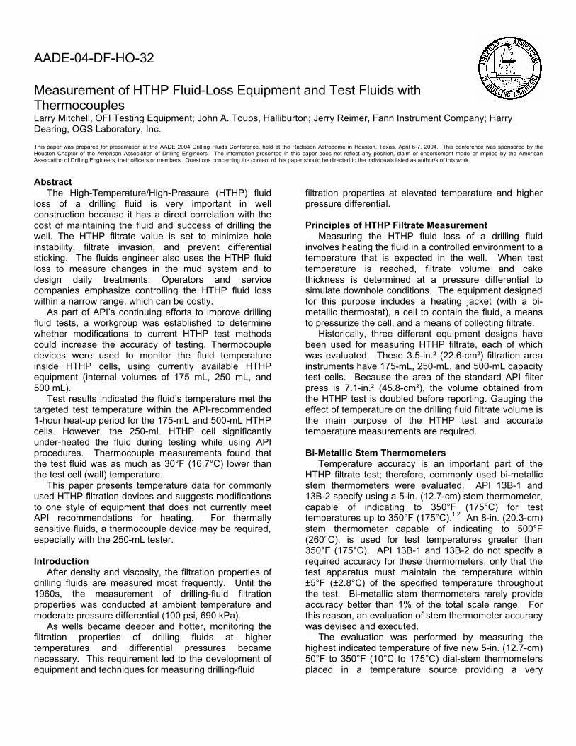
accurate temperature. These temperature sources are frequently used in calibrating many types of thermometers, thermocouples and instruments. The thermometers tested were randomly selected from recent purchases by a drilling-fluid equipment supplier. The temperature was increased in 50°F (27.8°C) increments, from 100°F (37.8°C) to 350°F (37.8°C). Table 1 summarizes the test results. Based upon this testing, it can be reasonably concluded that commonly used bi-metallic stem thermometers exhibit accuracy sufficient to meet current API specifications for HTHP fluid-loss testing. Gross temperature errors with these devices are likely a result of damaged or misadjusted thermometers, which should be easily detected with a periodic quality assurance process. Procedures for calibrating thermometers are given in the API Recommended Practices 13B-1 and 13B-2. These thermometers are provided with an external adjustment nut to facilitate recalibration. To recalibrate, adjust the thermometer by firmly holding the dial head, while immersing the stem at least 2-in. into a known temperature source (such as a water bath) and turn the hex nut with a wrench until the pointer indicates the correct temperature. Available HTHP Filter Press Models The three unique designs in common use are the 175-mL, 250-mL, and 500-mL HTHP filter presses. A description of each HTHP filter press is given in the following sections. 175-mL Filter Press Figure 1 shows the 175-mL HTHP model. Typically, the pressurization source is carbon dioxide cartridges. This model is rated to 350°F. 250-mL Filter Press Figure 2 shows the 250-mL HTHP model. As with the 175-mL model, the pressurization source is normally carbon dioxide cartridges. This model is also rated to 350°F. Early versions of this equipment had a back pressure receiver with a sight-glass, which was discontinued because of safety concerns. 500-mL Filter Press Figure 3 shows the 500-mL HTHP model, which is rated to 450°F. It requires pressurized nitrogen. In most areas, this device is considered a laboratory instrument and is most widely used in drilling fluid laboratories rather than field locations. Test Instrumentation To properly evaluate the heating ability and internal temperature of the different HTHP filter presses, nitrogen was used for pressure, and a different temperature control system (than the usual bi-metallic heating jacket
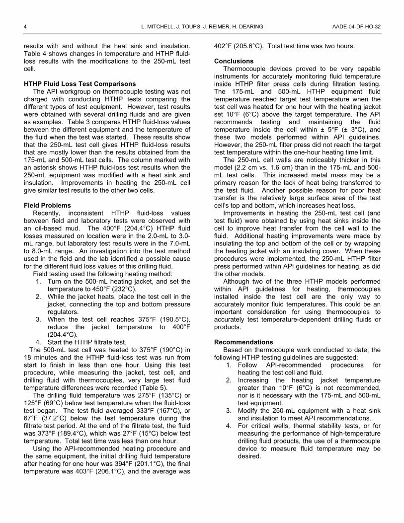
thermostat) was used. Two devices were used to control and measure the temperature of drilling fluids during each HTHP filtration test. The first device is a HTHP heating jacket controller (Figure 4). The jacket temperature is set with an electronic controller that uses a thermocouple to measure the jacket temperature. This device provides for quickly heating the jacket to the set temperature, then cycling the jacket to within ±5°F (±2.8°C) of the set temperature. The second device is a multichannel data acquisition system (Figure 5). The data acquisition unit measures three temperatures for each HTHP device. Using calibrated type K thermocouples, one channel records the temperature of the HTHP jacket, the second channel records the temperature of the HTHP test cell, and the third channel, using a type J thermocouple, measures the internal temperature of the drilling or test fluid (Figure 6). Instrument manufacturers supply calibrated type J thermocouple devices that are placed into the center of a HTHP filter cell to read the drilling fluid temperature approximately 1-in. above the filtration medium. Temperature measurements are recorded every ten seconds and saved to a spreadsheet by the data acquisition software. At the end of the test, a graph is prepared, showing the temperature profile of the jacket, test cell, and drilling fluid with respect to time (Figures 7 to 9). The accuracy of the type J and type K thermocouples used in this study was confirmed before testing. Test Procedure According to API procedures for HTHP testing (Recommended Practices 13B-1 and 13B-2), the jacket should be preheated to 10°F (5.6°C) above the test temperature. When the jacket reaches temperature, the test cell is placed in the jacket, the top and bottom pressure connections are made, and the pressurized test cell is allowed to heat. When the cell is within 5°F (2.8°C) of the test temperature, the top and bottom pressure is adjusted to the correct value, and the HTHP test begins. API recommendations are that the test cell and fluid should reach test temperature within one hour. In other words, the test should begin within one hour of placing the cell into the heating jacket. For the tests presented, the following procedure is used:
1. The HTHP jacket is preheated to 10°F (5.6°C) above the test temperature. The temperature controller maintains the jacket temperature at the correct value.
2. The test fluid is mixed for 10 minutes, added to the test cell and prepared for testing. A thermocouple is placed into the top portion of the test cell, threaded through the top port, and sealed.
3. The test cell is placed in the preheated jacket and thermocouples are connected to the data-

AADE-04-DF-HO-32 MEASUREMENT OF HTHP FLUID LOSS EQUIPMENT AND TEST FLUIDS WITH THERMOCOUPLES 3
acquisition system to measure the jacket, test cell, and internal fluid temperatures. Computer data acquisition begins.
4. Top and bottom pressure regulators are connected. Nitrogen gas is applied through the top valve at 100 psi (690 kPa).
5. The pressurized test cell and fluid is allowed to heat for 60 minutes.
6. At the end of 60 minutes, the pressure on the top regulator is increased to 600 psi (4,140 kPa) and the bottom receiver pressure is adjusted to 100 psi (690 kPa), resulting in a 500-psi differential pressure across the filter paper.
7. The bottom test cell valve is opened to start the test.
8. After 30 minutes, the bottom valve is closed to end the test.
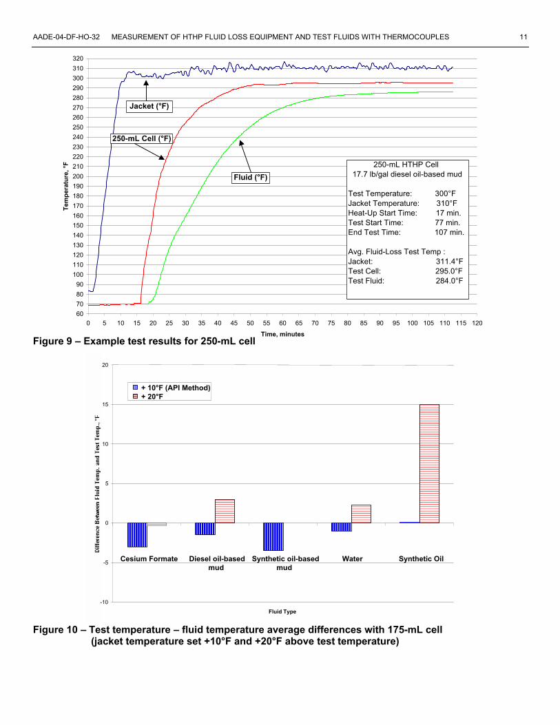
9. Filtrate volume is measured and recorded. Figures 7 through 9 illustrate the test data and temperature profiles of typical HTHP filtration tests using the instrumented cells. More than one hundred thermocouple tests were conducted using the 175-mL, 250-mL, and 500-mL style HTHP filter presses. Many different types of fluids were tested, including fresh water, mineral oil, water-based mud, oil-based mud, and completion fluid. For most tests, only the heating characteristics of the cell were measured during the one-hour heating period. Other tests included measuring the HTHP filtrate (for 30 minutes) of fluids after the 60-minute heating period, resulting in temperature data collected for the 1½-hour time period. Differential temperature test data is obtained by subtracting the measured fluid temperature from the target test temperature. An example of data collected for analysis is seen in Table 2. Variations from Standard Procedure To decrease the time required to run HTHP tests, a common practice is to set the temperature of the heating jacket 20°F to 30°F or more (11.1°C to 16.7°C) above the target test temperature. This variation to the recommended procedure was used on selected HTHP tests to evaluate the effect on the fluid temperature inside the cell. Test Results 175-mL and 500-mL HTHP Equipment Using the API-recommended heating procedure, thermocouple measurements indicated the 175-mL HTHP cell heated the test fluid to within an average of 3°F (1.6°C) of the target test temperature within the 60-minute heat-up time. When the heating jacket temperature was increased 20°F (11°C) above the test temperature, the internal fluid temperature was consistently 2°F (1.1°C) to 12°F (6.7°C) above the test temperature at 60 minutes (Figure 10).
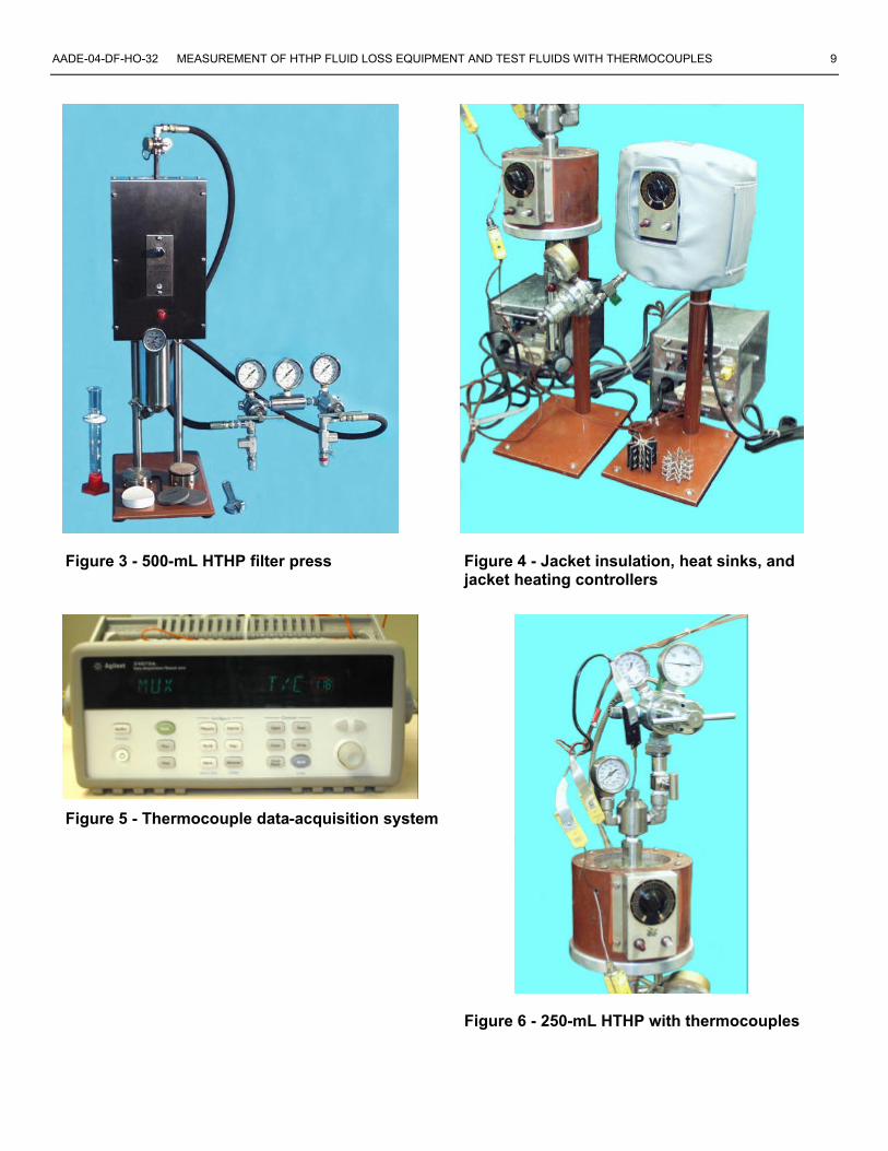
Results with the 500-mL HTHP equipment were similar to the 175-mL equipment. The API procedure heated the test fluid to ± 5°F (± 2.8°C) of the test temperature within the one hour heat-up time. When the jacket temperature was set 20°F above the test temperature, the test fluid was consistently heated above the test temperature by 1°F to 18°F (0.6°C to 10.0°C) (Figure 11). 250-mL HTHP Equipment Using the API recommended heating procedure, thermocouple measurements indicate the 250-mL style equipment does not consistently heat the fluid to the test temperature. Test cell temperature readings from 25 tests averaged 8°F (4.4°C) below the test temperature after heating for 60 minutes. Test fluid temperature averaged 16°F (8.9°C) below the test temperature during these tests. When the jacket is set 20°F (11.1°C) above the target test temperature, the test cell reaches the proper temperature, averaging 1°F (0.6°C) over test temperature for ten tests. However, the average fluid temperature is 10°F (5.6°C) below the test temperature. Figure 12 shows the average temperature differences between the fluid and the test temperature. Figure 13 shows 250-mL HTHP equipment temperature differentials between:
• the heating jacket and test temperature • the test cell and heating jacket • the test fluid and heating jacket • the test fluid and test cell • the test fluid and target test temperature
This data indicates that the 250-mL HTHP equipment has a problem transferring heat from the jacket to the test cell and then to the test fluid. Not all types of fluids or jacket temperatures were run in the data presented in Figures 10 through 13. Heating Improvements to 250-mL HTHP Equipment The size, configuration, and wall thickness of the 250-mL test cell prevents the fluid from being heated to the correct temperature when using the API procedure. Several modifications to improve heating performance were evaluated. Placing a metal heat sink (Figures 14 and 15) inside the test cell, as well as covering the top and bottom of the cell with high-temperature aluminum oxide insulation (Figure 16), dramatically improved the performance of this equipment. On tests with the heat sink and insulation, the fluid temperature increased by an average of 16°F (8.9°C). These modifications brought the 250-mL equipment within API recommendations. Differences in HTHP fluid-loss results were minor and could be attributed to the increased temperature of the fluid during the test. Two types of heat sinks, as well as an insulation jacket, are shown in Figure 4. Close-ups of the heat sinks are shown in Figures 14 and 15. Table 3 compares test
4 L. MITCHELL, J. TOUPS, J. REIMER, H. DEARING AADE-04-DF-HO-32
results with and without the heat sink and insulation. Table 4 shows changes in temperature and HTHP fluid-loss results with the modifications to the 250-mL test cell. HTHP Fluid Loss Test Comparisons The API workgroup on thermocouple testing was not charged with conducting HTHP tests comparing the different types of test equipment. However, test results were obtained with several drilling fluids and are given as examples. Table 3 compares HTHP fluid-loss values between the different equipment and the temperature of the fluid when the test was started. These results show that the 250-mL test cell gives HTHP fluid-loss results that are mostly lower than the results obtained from the 175-mL and 500-mL test cells. The column marked with an asterisk shows HTHP fluid-loss test results when the 250-mL equipment was modified with a heat sink and insulation. Improvements in heating the 250-mL cell give similar test results to the other two cells. Field Problems Recently, inconsistent HTHP fluid-loss values between field and laboratory tests were observed with an oil-based mud. The 400°F (204.4°C) HTHP fluid losses measured on location were in the 2.0-mL to 3.0-mL range, but laboratory test results were in the 7.0-mL to 8.0-mL range. An investigation into the test method used in the field and the lab identified a possible cause for the different fluid loss values of this drilling fluid. Field testing used the following heating method:
1. Turn on the 500-mL heating jacket, and set the temperature to 450°F (232°C).
2. While the jacket heats, place the test cell in the jacket, connecting the top and bottom pressure regulators.
3. When the test cell reaches 375°F (190.5°C), reduce the jacket temperature to 400°F (204.4°C).
4. Start the HTHP filtrate test. The 500-mL test cell was heated to 375°F (190°C) in 18 minutes and the HTHP fluid-loss test was run from start to finish in less than one hour. Using this test procedure, while measuring the jacket, test cell, and drilling fluid with thermocouples, very large test fluid temperature differences were recorded (Table 5). The drilling fluid temperature was 275°F (135°C) or 125°F (69°C) below test temperature when the fluid-loss test began. The test fluid averaged 333°F (167°C), or 67°F (37.2°C) below the test temperature during the filtrate test period. At the end of the filtrate test, the fluid was 373°F (189.4°C), which was 27°F (15°C) below test temperature. Total test time was less than one hour. Using the API-recommended heating procedure and the same equipment, the initial drilling fluid temperature after heating for one hour was 394°F (201.1°C), the final temperature was 403°F (206.1°C), and the average was
402°F (205.6°C). Total test time was two hours. Conclusions Thermocouple devices proved to be very capable instruments for accurately monitoring fluid temperature inside HTHP filter press cells during filtration testing. The 175-mL and 500-mL HTHP equipment fluid temperature reached target test temperature when the test cell was heated for one hour with the heating jacket set 10°F (6°C) above the target temperature. The API recommends testing and maintaining the fluid temperature inside the cell within ± 5°F (± 3°C), and these two models performed within API guidelines. However, the 250-mL filter press did not reach the target test temperature within the one-hour heating time limit. The 250-mL cell walls are noticeably thicker in this model (2.2 cm vs. 1.6 cm) than in the 175-mL and 500-mL test cells. This increased metal mass may be a primary reason for the lack of heat being transferred to the test fluid. Another possible reason for poor heat transfer is the relatively large surface area of the test cell’s top and bottom, which increases heat loss. Improvements in heating the 250-mL test cell (and test fluid) were obtained by using heat sinks inside the cell to improve heat transfer from the cell wall to the fluid. Additional heating improvements were made by insulating the top and bottom of the cell or by wrapping the heating jacket with an insulating cover. When these procedures were implemented, the 250-mL HTHP filter press performed within API guidelines for heating, as did the other models. Although two of the three HTHP models performed within API guidelines for heating, thermocouples installed inside the test cell are the only way to accurately monitor fluid temperatures. This could be an important consideration for using thermocouples to accurately test temperature-dependent drilling fluids or products.
Recommendations Based on thermocouple work conducted to date, the following HTHP testing guidelines are suggested:
1. Follow API-recommended procedures for heating the test cell and fluid.
2. Increasing the heating jacket temperature greater than 10°F (6°C) is not recommended, nor is it necessary with the 175-mL and 500-mL test equipment.
3. Modify the 250-mL equipment with a heat sink and insulation to meet API recommendations.
4. For critical wells, thermal stability tests, or for measuring the performance of high-temperature drilling fluid products, the use of a thermocouple device to measure fluid temperature may be desired.

AADE-04-DF-HO-32 MEASUREMENT OF HTHP FLUID LOSS EQUIPMENT AND TEST FLUIDS WITH THERMOCOUPLES 5
Acknowledgments Dr. Leon Robinson, PhD (retired) suggested the use of a heat sink in the 250-mL instrument. His help with this matter and other technical problems is greatly appreciated. Willie Vasquez and Irina Goldenberg (Westport Technology Center International) spent many hours testing different fluids and measuring HTHP equipment heating characteristics. Their hard work increased our understanding of HTHP filtration equipment. Their work and suggestions are also greatly appreciated.
References 1. Recommended Practice Standard Procedure for Field
Testing Water-Based Drilling Fluids, API Recommended Practice 13B-1, Second Edition 1997.
2. Recommended Practice Standard Procedure for Field
Testing Oil-Based Drilling Fluids, API Recommended Practice 13B-2, Third Edition 1998.
Table 1 – Bi-Metallic Stem Thermometer Measurements
Test Minimum Maximum Average Temp, °F Temp, °F Temp, °F Temp, °F
100°F 102°F 104°F 104°F 150°F 150°F 152°F 151°F 200°F 200°F 203°F 202°F 250°F 251°F 256°F 253°F 300°F 300°F 306°F 303°F 350°F 352°F 356°F 354°F

6 L. MITCHELL, J. TOUPS, J. REIMER, H. DEARING AADE-04-DF-HO-32
Table 2 – Examples of Thermocouple HTHP Heating Test Data
Target Jacket Jacket Jacket at Cell at Fluid at Mud
Test Test Setting Over 60 min., 60 min., 60 min., Mud Weight Cell Temp (°F) (°F) Test (°F) (°F) (°F) (°F) Type (lb/gal) 175 250 260 10 258 254 245 synthetic 10.5 250 250 260 10 257 239 221 synthetic 10.5 500 250 260 10 261 256 247 synthetic 10.5 175 300 310 10 310 308 301 diesel obm 17.7 250 300 310 10 310 294 282 diesel obm 17.7 500 300 310 10 310 306 306 diesel obm 17.7 175 300 320 20 320 316 308 diesel obm 17.7 250 300 320 20 318 300 285 diesel obm 17.7 500 300 320 20 319 318 317 diesel obm 17.7 175 350 370 20 367 360 348 diesel obm 17.7 250 350 370 20 367 340 327 diesel obm 17.7 500 350 370 20 368 357 355 diesel obm 17.7 175 250 260 10 260 252 250 water 8.3 250 250 260 10 261 247 245 water 8.3 500 250 260 10 259 252 250 water 8.3 175 300 310 10 302 297 295 water 8.3 250 300 310 10 302 284 282 water 8.3 500 300 310 10 310 302 300 water 8.3 175 250 270 20 267 252 250 water 8.3 250 250 270 20 270 250 250 water 8.3 500 250 270 20 270 263 262 water 8.3 175 300 320 20 320 308 306 water 8.3 250 300 320 20 319 299 295 water 8.3 500 300 320 20 319 311 310 water 8.3 175 320 340 20 339 336 320 Cs formate 17.0 250 350 370 20 366 335 320 Cs formate 17.0 500 320 340 20 337 337 324 Cs formate 17.0

AADE-04-DF-HO-32 MEASUREMENT OF HTHP FLUID LOSS EQUIPMENT AND TEST FLUIDS WITH THERMOCOUPLES 7
Table 3 – HTHP Fluid Loss Test Results of Drilling Fluids
10.5-lb/gal Synthetic, 250°F
175-mL
500-mL
250-mL
15.0-lb/gal Synthetic, 300°F
175-mL
500-mL
250-mL
HTHP (mL/30 min) 3.8 3.4 3.2 HTHP (mL/30 min) 4.0 4.0 3.2 Fluid Start temp.(°F) 245 247 221 (water in filt., mL) 0.4 0.4 0.4
Fluid Start temp.(°F) 298 299 281
11.1-lb/gal Synthetic, 250°F
250-mL
250-mL*
15.9-lb/gal Diesel OBM
175-mL
500-mL
250-mL
HTHP (mL/30 min) 3.6 5.6 HTHP (mL/30 min) 14.4 15.2 9.6 Fluid Start temp.(°F) 235 242 (water in filt., mL) 3.6 3.6 3.2 Fluid Start temp.(°F) 297 299 283 16.3-lb/gal Synthetic, 250°F
250-mL
250-mL*
16.8-lb/gal Diesel OBM, 375°F
500-mL
250-mL
250-mL*
HTHP (mL/30 min) 1.2 1.6 HTHP (mL/30 min) 4.8 4.0 3.2 Fluid Start temp.(°F) 235 243 Fluid Start temp.(°F) 375 351 364 * Indicates 250-mL cell modified with heat sink and insulation
Table 4 – Effect of Modifying 250-mL HTHP Cell with Heat Sinks, Aluminum Oxide Insulation, or Insulation Jacket
Start Water Start 13.6-lb/gal Temp. HTHP In Filt. 11.0 lb/gal Temp. HTHP Synthetic Mud, 300°F (°F) Filt., (mL) (mL) Lignite Mud, 300°F (°F) Filt., (mL) Heat Sink Type A 286 9.6 2.0 Base Mud 279 20.8 Heat Sink Type B 285 10.0 2.0 Heat Sink A 298 21.6 Insulation jacket 283 9.6 0.0 HS A, Top/Bottom Ins. 294 20.4 HS A, Insulation jacket 298 8.8 0.0 HS A, Top/Bottom Ins. 298 12.4 4.0 Start HS B, Top/Bottom Ins. 288 12.4 4.4 11.0 lb/gal Temp. HTHP
Lignosulfonate, 300°F (°F) Filt., (mL) Start Base Mud 278 19.2
16.8-lb/gal Temp. HTHP HS A, Top/Bottom Ins. 299 18.8 Diesel OBM, 375°F (°F) Filt., (mL) Base Mud (500-mL cell) 375 4.8 Start Base Mud (250-mL cell) 351 4.0 15.0 lb/gal Temp. HTHP Base Mud (250-mL cell)* 361 6.0 Lignosulfonate, 300°F (°F) Filt., (mL) Heat Sink A only 364 3.2 Base Mud 284 17.2 Top Insulation only 365 not run HS A, Top/Bottom Ins. 292 17.2 Top/Bottom Ins. only 356 not run
HS A, Top/Bottom Ins. 372 not run
* Jacket temperature set 30°F above target temperature

8 L. MITCHELL, J. TOUPS, J. REIMER, H. DEARING AADE-04-DF-HO-32
Table 5 – Field Problem Test Data, Results of Overheating Jacket to Minimize HTHP Test Time
Test Drilling API Test Jacket Cell Fluid Fluid*
Initial Temperature (°F) 450 75 75 75 Start Test Temp. (°F) 425 376 275 394 End Test Temp. (°F) 398 392 373 403 Average Temp. (°F) 405 391 333 402
Total Test Time, min. - - 48 120
* API method (preheat jacket, heat cell for 60 minutes)
Figure 1 Figure 2 175-mL HTHP filter press 250-mL HTHP filter press
AADE-04-DF-HO-32 MEASUREMENT OF HTHP FLUID LOSS EQUIPMENT AND TEST FLUIDS WITH THERMOCOUPLES 9
Figure 3 - 500-mL HTHP filter press Figure 4 - Jacket insulation, heat sinks, and jacket heating controllers
Figure 5 - Thermocouple data-acquisition system
Figure 6 - 250-mL HTHP with thermocouples

10 L. MITCHELL, J. TOUPS, J. REIMER, H. DEARING AADE-04-DF-HO-32
Figure 7 – Example test results for 175-mL cell
Figure 8 – Example test results for 500-mL cell
60
70
80
90
100
110
120
130
140
150
160
170
180
190200
210
220230
240
250
260
270
280
290
300310
320
0 5 10 15 20 25 30 35 40 45 50 55 60 65 70 75 80 85 90 95 100 105 110 115 120
Time, minutes
Tem
per
atu
re, °
F
500 Jacket500 Cell500 Fluid
500-mL HTHP Cell 17.7-lb/gal diesel oil-based mud
Test Temperature: 300°FJacket Temperature: 310°FHeat-Up Start Time: 27 min.Test Start Time: 87 min.End Test Time: 117 min.
Avg. Fluid Loss Test Temp :Jacket: 309.9°FTest Cell: 306.3°FTest Fluid: 307.5°F
Jacket (°F)
500-mL Cell (°F)
Fluid (°F)
60
7080
90
100
110
120
130
140
150
160
170
180
190200
210
220230
240
250
260
270
280
290
300
310
320
0 5 10 15 20 25 30 35 40 45 50 55 60 65 70 75 80 85 90 95 100 105 110 115 120
Time, minutes
Tem
per
atu
re, °
F
175 Jacket175 Cell175 Fluid
175-mL HTHP cell 17.7-lb/gal diesel oil-based mud
Test Temperature: 300°FJacket Temperature: 310°FHeat-Up Start Time: 22 min.Test Start Time: 82 min.End Test Time: 112 min.
Avg. Fluid-Loss Test Temp. :Jacket: 309.1°FTest Cell: 307.6°FTest Fluid: 302.1°F
Start Heating
Jacket (°F)
175-mL Cell (°F)
Fluid (°F)
Start FiltrateTest
End Filtrate Test
AADE-04-DF-HO-32 MEASUREMENT OF HTHP FLUID LOSS EQUIPMENT AND TEST FLUIDS WITH THERMOCOUPLES 11
Figure 9 – Example test results for 250-mL cell
Figure 10 – Test temperature – fluid temperature average differences with 175-mL cell (jacket temperature set +10°F and +20°F above test temperature)
Fluid Type -10
-5
0
5
10
15
20
Cesium Formate Diesel oil-based mud
Synthetic oil-based mud
Water Synthetic Oil
+ 10°F (API Method) + 20°F
60
70
80
90
100
110
120
130
140
150160
170
180
190
200
210
220
230
240
250
260
270
280
290
300
310
320
0 5 10 15 20 25 30 35 40 45 50 55 60 65 70 75 80 85 90 95 100 105 110 115 120
Time, minutes
Tem
per
atu
re, °
F
250 Jacket250 Cell250 Fluid
250-mL HTHP Cell 17.7 lb/gal diesel oil-based mud
Test Temperature: 300°FJacket Temperature: 310°FHeat-Up Start Time: 17 min.Test Start Time: 77 min.End Test Time: 107 min.
Avg. Fluid-Loss Test Temp :Jacket: 311.4°FTest Cell: 295.0°FTest Fluid: 284.0°F
Jacket (°F)
250-mL Cell (°F)
Fluid (°F)

12 L. MITCHELL, J. TOUPS, J. REIMER, H. DEARING AADE-04-DF-HO-32
Figure 11 – Test temperature – fluid temperature average differences with 500-mL cell (jacket temperature set +10°F and +20°F above test temperature)
Figure 12 – Test temperature – fluid temperature average differences with 250-mL cell (jacket temperature set +10°F, +20°F, and +30°F above test temperature) Note: Diesel OBM was only fluid tested at all three temperatures
Cesium Formate Diesel oil-based mud
Synthetic oil- based mud
Water Lignite Fluid Lignosulfonate Fluid
Synthetic Oil -30
-25
-20
-15
-10
-5
0
5
10
Dif
fere
nce
Bet
wee
n F
luid
Tem
p. a
nd
Tes
t T
emp
., °F
+ 10°F (API Method) + 20°F + 30°F
Fluid Type
-10
-5
0
5
10
15
20
Dif
fere
nce
Bet
wee
n F
luid
Tem
p. a
nd
Tes
t T
emp
., °F
+ 10°F (API Method) + 20°F
Cesium Formate Diesel oil-based mud Synthetic oil-based mud
Water Synthetic Oil

AADE-04-DF-HO-32 MEASUREMENT OF HTHP FLUID LOSS EQUIPMENT AND TEST FLUIDS WITH THERMOCOUPLES 13
Figure 13 – 250-mL jacket, cell, and fluid average temperature differentials (jacket set +10°F, +20°F, and +30°F above test temperature)
Figure 14 – Heat sink A for 250-mL cell Figure 15 – Heat sink B for 250-mL cell
Test Fluid (jacket temperature setting above test temperature)
-50
-40
-30
-20
-10
0
10
20
30
40
50
Tem
per
atu
re V
aria
nce
, °F
Diesel oil- Diesel oil- Diesel oil- Synthetic oil- Synthetic oil- Water (+10°F) Water (+20°F)
Jacket - Test Temp.Cell - Jacket Temp.Fluid - Jacket Temp.Fluid - Cell Temp.Fluid - Test Temp.
Diesel oil- based mud (+10°F)
Diesel oil- based mud (+20°F)
Diesel oil- based mud (+30°F)
Synthetic oil- based mud (+10°F)
Synthetic oil- based mud (+20°F)
Water Water
(+10°F) (+20°F)

14 L. MITCHELL, J. TOUPS, J. REIMER, H. DEARING AADE-04-DF-HO-32
Figure 16 – Aluminum oxide top insulation for 250-mL cell