aabc commissioning group · 2019-04-24 · aabc commissioning group. aia provider number 50111116....
TRANSCRIPT
AABC Commissioning GroupAIA Provider Number 50111116
Leakage Testing of HVAC Systems
Course Number: CXENERGY1930
Mike KellyAmerican Testing Inc.
April 16, 2019

Test & Balance Seminar for CxAs, Engineers, & TAB Professionals
Tuesday, April 16, 2019
8:30 a.m. – 4:30 p.m.
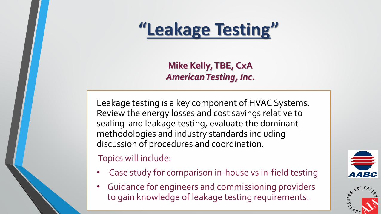
“Leakage Testing”
Mike Kelly, TBE, CxAAmerican Testing, Inc.
Leakage testing is a key component of HVAC Systems. Review the energy losses and cost savings relative to sealing and leakage testing, evaluate the dominant methodologies and industry standards including discussion of procedures and coordination.
Topics will include:
• Case study for comparison in-house vs in-field testing
• Guidance for engineers and commissioning providers to gain knowledge of leakage testing requirements.
AIA Credits
This course is registered with AIA CES for continuing professional education. As such, it does not include content that may be deemed or construed to be
an approval or endorsement by the AIA of any material of construction or any method or manner of handling, using, distributing, or dealing in any
material or product.
Credit(s) earned on completion of this course will be reported to AIA CES for AIA members. Certificates of Completion for both AIA members and non-
AIA members are available upon request.
Questions related to specific materials, methods and services will be addressed at the conclusion of this
presentation
Copyright Materials
This presentation is protected by U.S. and International Copyright laws.
Reproduction, distribution, display, and use of the presentation without written
permission of the speaker is prohibited.
© American Testing, Inc. 2019
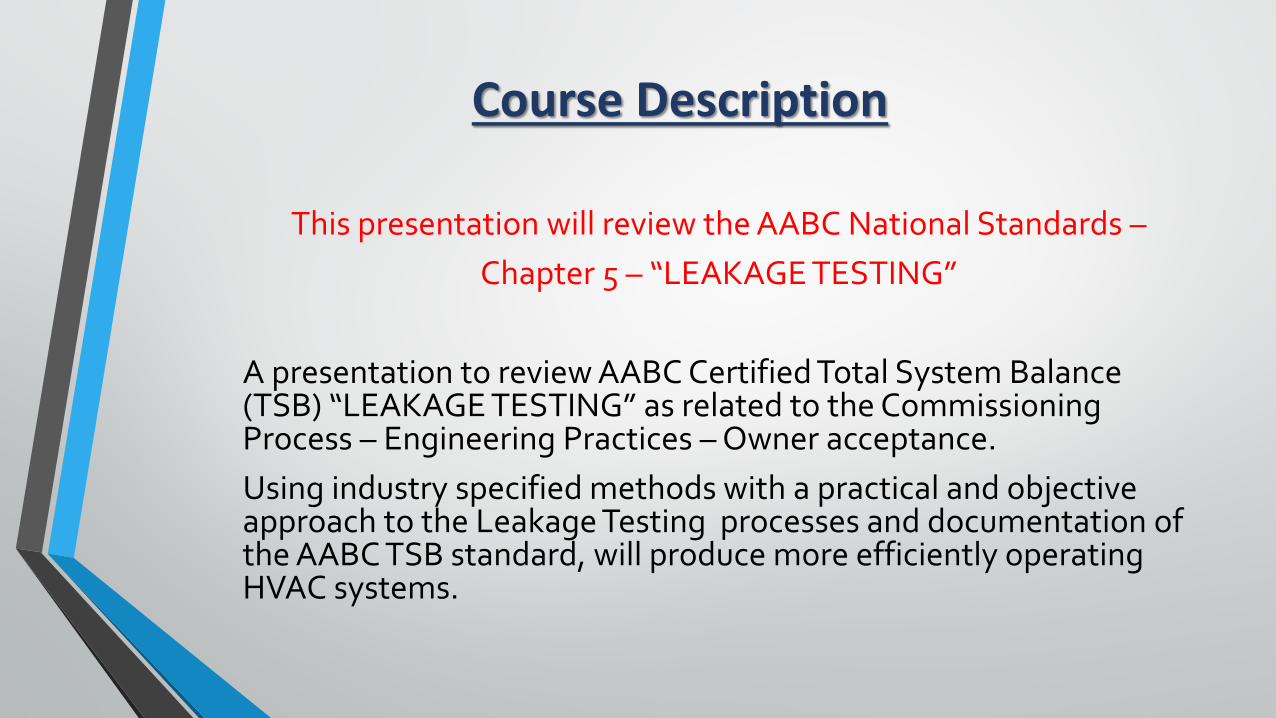
Course Description
This presentation will review the AABC National Standards –Chapter 5 – “LEAKAGE TESTING”
A presentation to review AABC Certified Total System Balance (TSB) “LEAKAGE TESTING” as related to the Commissioning Process – Engineering Practices – Owner acceptance. Using industry specified methods with a practical and objective approach to the Leakage Testing processes and documentation of the AABC TSB standard, will produce more efficiently operating HVAC systems.
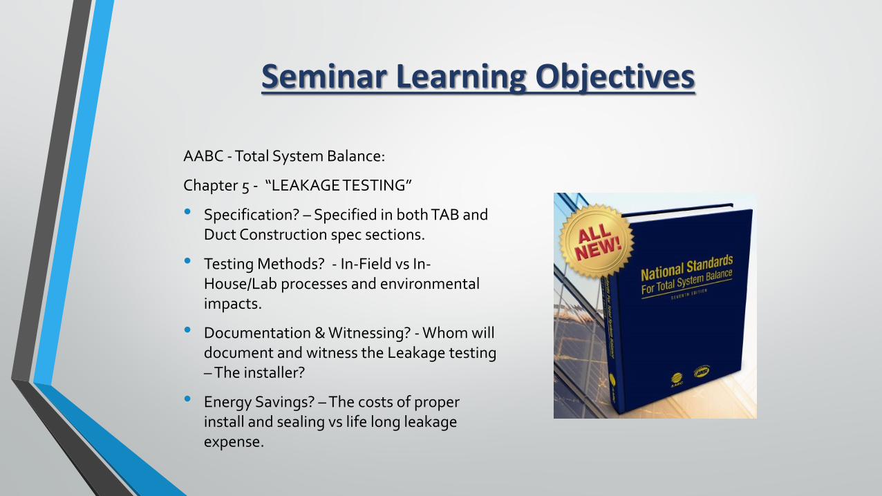
Seminar Learning Objectives
AABC - Total System Balance:
Chapter 5 - “LEAKAGE TESTING”
• Specification? – Specified in both TAB and Duct Construction spec sections.
• Testing Methods? - In-Field vs In-House/Lab processes and environmental impacts.
• Documentation & Witnessing? - Whom will document and witness the Leakage testing – The installer?
• Energy Savings? – The costs of proper install and sealing vs life long leakage expense.
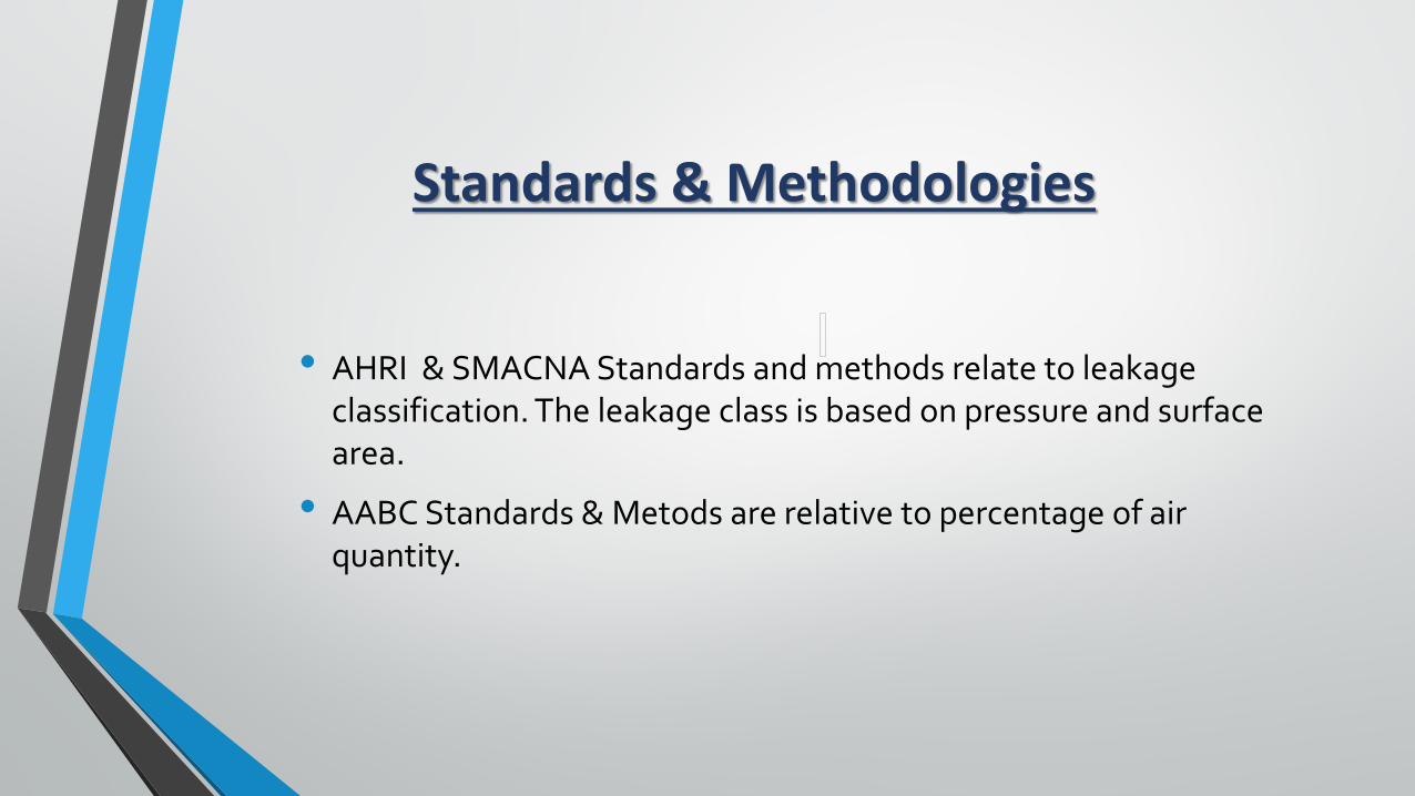
Standards & Methodologies
• AHRI & SMACNA Standards and methods relate to leakage classification. The leakage class is based on pressure and surface area.
• AABC Standards & Metods are relative to percentage of air quantity.
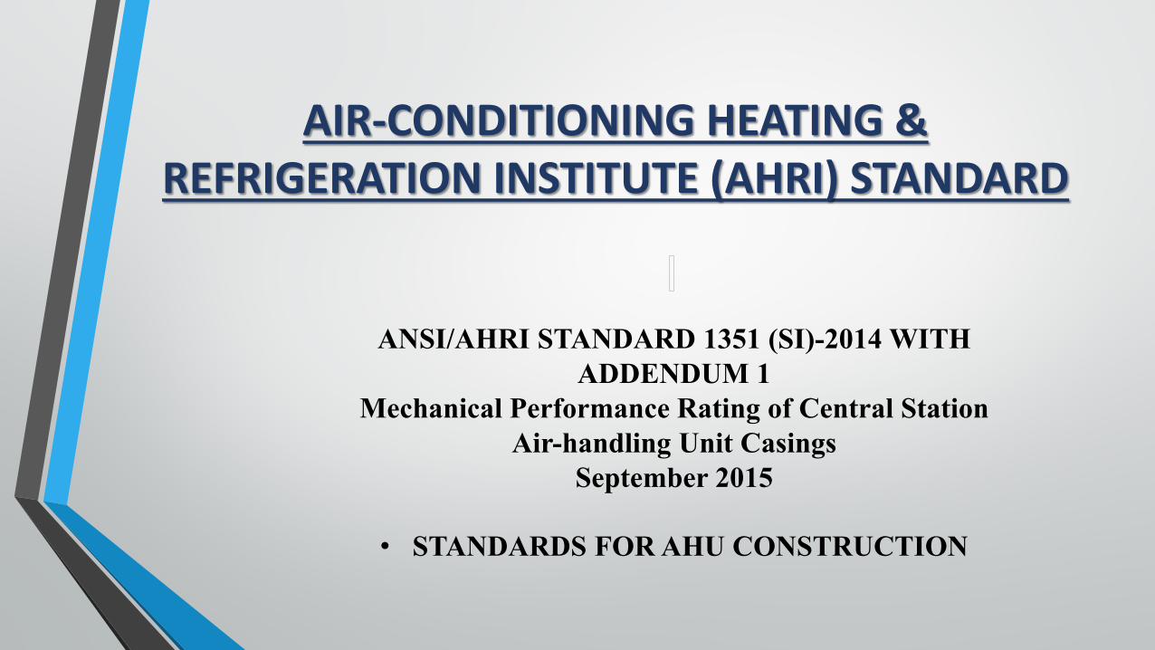
AIR-CONDITIONING HEATING & REFRIGERATION INSTITUTE (AHRI) STANDARD
ANSI/AHRI STANDARD 1351 (SI)-2014 WITHADDENDUM 1
Mechanical Performance Rating of Central StationAir-handling Unit Casings
September 2015
• STANDARDS FOR AHU CONSTRUCTION
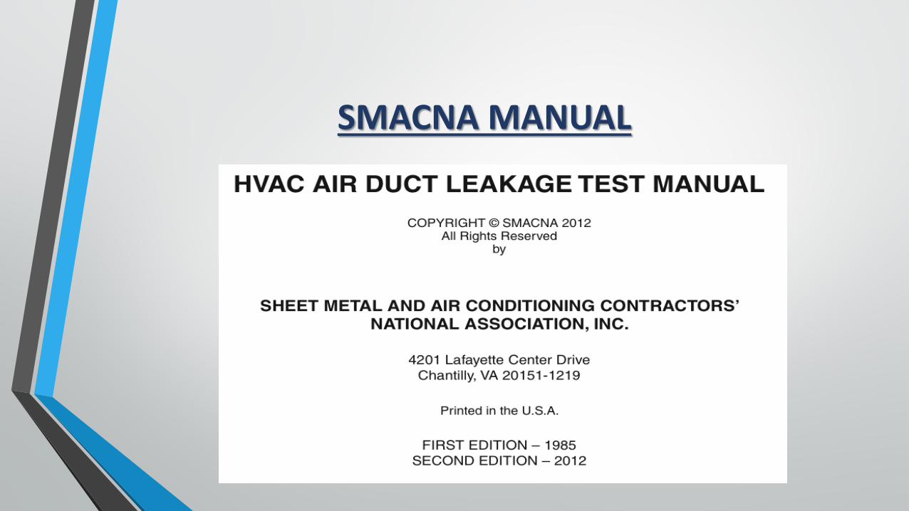
SMACNA MANUAL
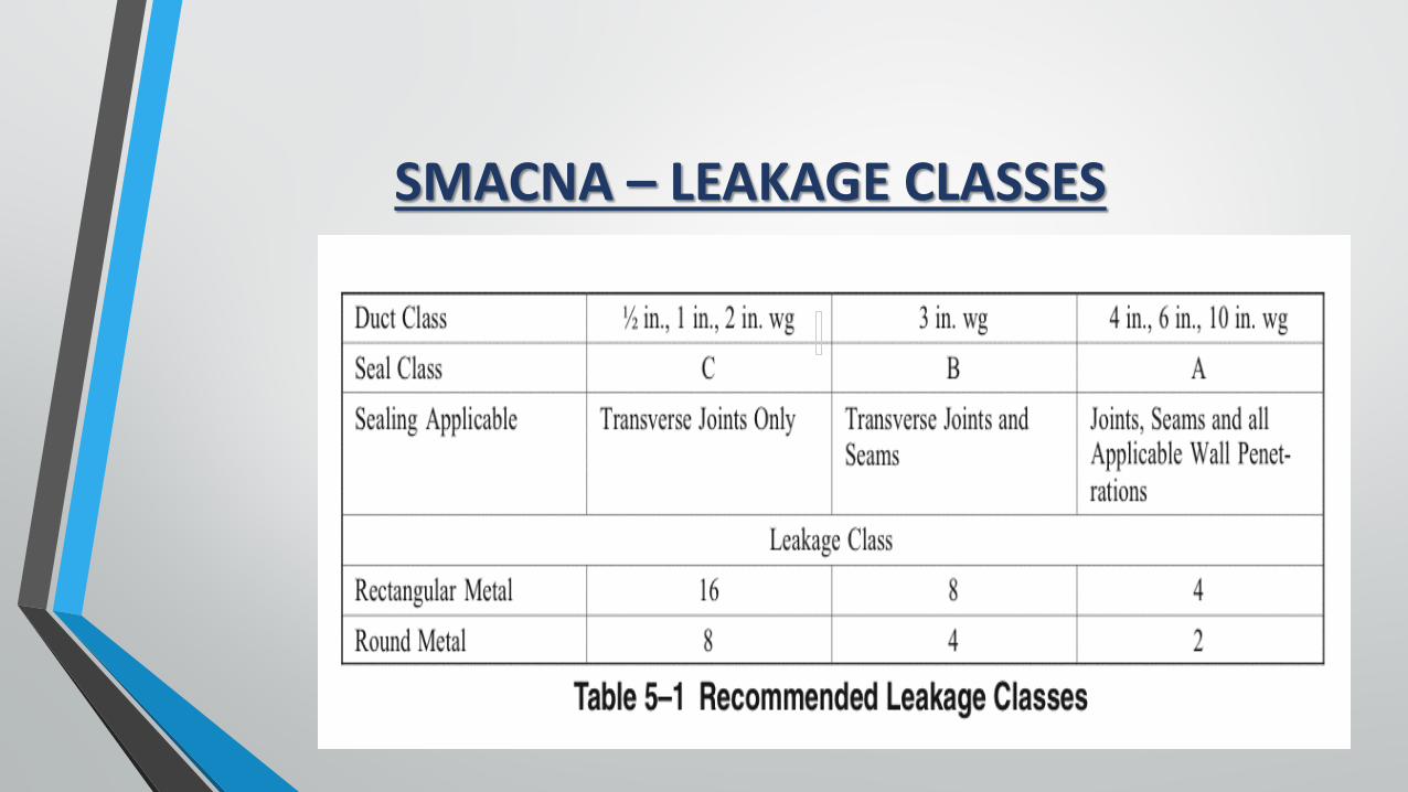
SMACNA – LEAKAGE CLASSES
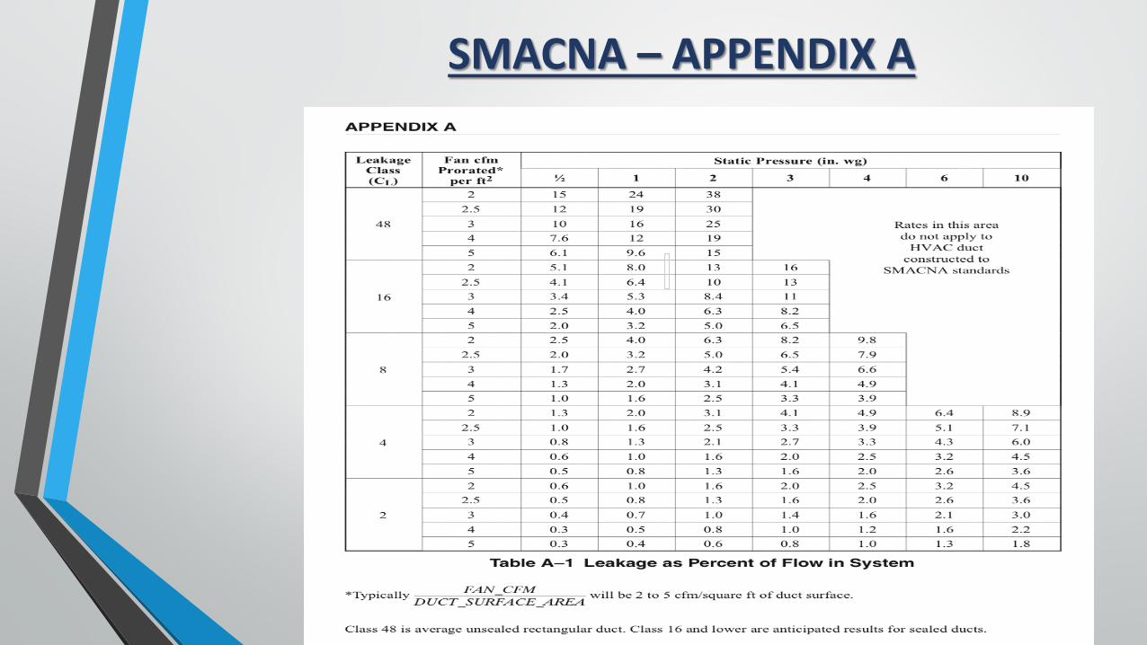
SMACNA – APPENDIX A
AABC – CHAPTER 5 - OVERVIEW
• Duct leakage testing is an additional test, not considered part of AABC Total System Balancing unless specifically specified.
• The AABC recommends that the leakage testing be specified in both the testing and balancing section, as well as the duct construction section of the specifications.
• Since contractors are responsible for the construction and sealing of the duct, it is their responsibility to prepare the system for testing, and provide initial testing to assure a successful outcome at the final witnessed test.
• The TAB agency shall provide the calibrated instrumentation and be an independent witness to the testing.
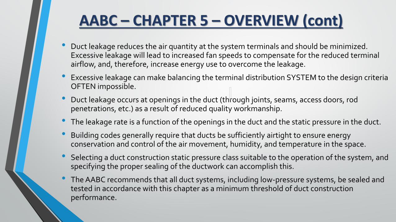
AABC – CHAPTER 5 – OVERVIEW (cont)• Duct leakage reduces the air quantity at the system terminals and should be minimized.
Excessive leakage will lead to increased fan speeds to compensate for the reduced terminal airflow, and, therefore, increase energy use to overcome the leakage.
• Excessive leakage can make balancing the terminal distribution SYSTEM to the design criteria OFTEN impossible.
• Duct leakage occurs at openings in the duct (through joints, seams, access doors, rod penetrations, etc.) as a result of reduced quality workmanship.
• The leakage rate is a function of the openings in the duct and the static pressure in the duct.
• Building codes generally require that ducts be sufficiently airtight to ensure energy conservation and control of the air movement, humidity, and temperature in the space.
• Selecting a duct construction static pressure class suitable to the operation of the system, and specifying the proper sealing of the ductwork can accomplish this.
• The AABC recommends that all duct systems, including low-pressure systems, be sealed and tested in accordance with this chapter as a minimum threshold of duct construction performance.
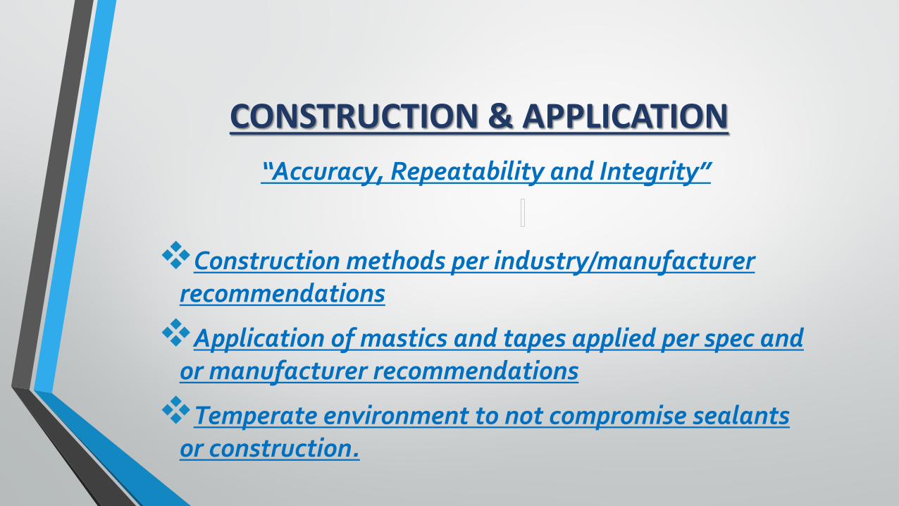
CONSTRUCTION & APPLICATION“Accuracy, Repeatability and Integrity”
Construction methods per industry/manufacturer recommendations
Application of mastics and tapes applied per spec and or manufacturer recommendations
Temperate environment to not compromise sealants or construction.
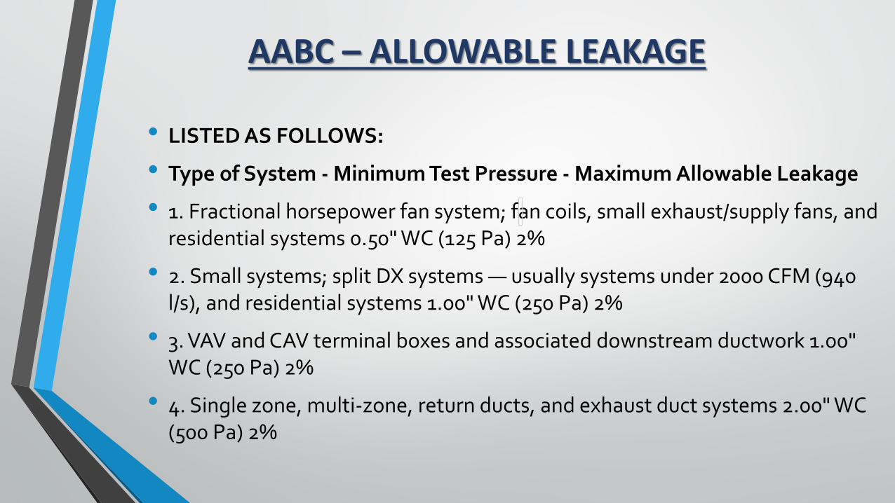
AABC – ALLOWABLE LEAKAGE
• LISTED AS FOLLOWS:
• Type of System - Minimum Test Pressure - Maximum Allowable Leakage
• 1. Fractional horsepower fan system; fan coils, small exhaust/supply fans, and residential systems 0.50" WC (125 Pa) 2%
• 2. Small systems; split DX systems — usually systems under 2000 CFM (940 l/s), and residential systems 1.00" WC (250 Pa) 2%
• 3. VAV and CAV terminal boxes and associated downstream ductwork 1.00" WC (250 Pa) 2%
• 4. Single zone, multi-zone, return ducts, and exhaust duct systems 2.00" WC (500 Pa) 2%
AABC - ALLOWABLE LEAKAGE (cont)
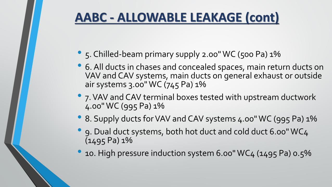
• 5. Chilled-beam primary supply 2.00" WC (500 Pa) 1%• 6. All ducts in chases and concealed spaces, main return ducts on
VAV and CAV systems, main ducts on general exhaust or outside air systems 3.00" WC (745 Pa) 1%
• 7. VAV and CAV terminal boxes tested with upstream ductwork 4.00" WC (995 Pa) 1%
• 8. Supply ducts for VAV and CAV systems 4.00" WC (995 Pa) 1%• 9. Dual duct systems, both hot duct and cold duct 6.00" WC4
(1495 Pa) 1%• 10. High pressure induction system 6.00" WC4 (1495 Pa) 0.5%
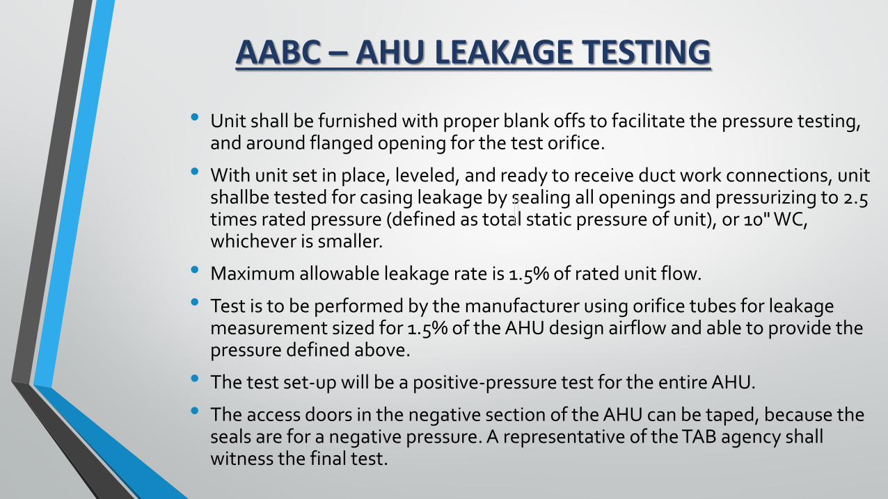
AABC – AHU LEAKAGE TESTING
• Unit shall be furnished with proper blank offs to facilitate the pressure testing, and around flanged opening for the test orifice.
• With unit set in place, leveled, and ready to receive duct work connections, unit shallbe tested for casing leakage by sealing all openings and pressurizing to 2.5 times rated pressure (defined as total static pressure of unit), or 10" WC, whichever is smaller.
• Maximum allowable leakage rate is 1.5% of rated unit flow.
• Test is to be performed by the manufacturer using orifice tubes for leakage measurement sized for 1.5% of the AHU design airflow and able to provide the pressure defined above.
• The test set-up will be a positive-pressure test for the entire AHU.
• The access doors in the negative section of the AHU can be taped, because the seals are for a negative pressure. A representative of the TAB agency shall witness the final test.
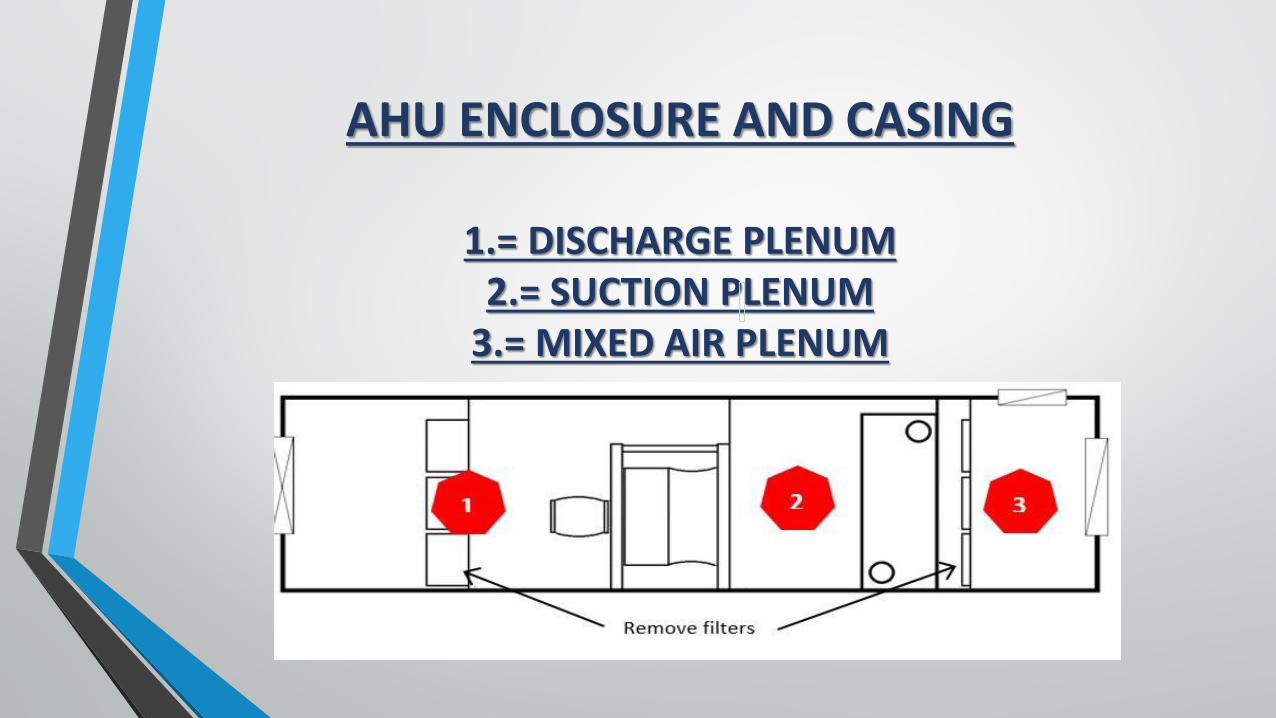
AHU ENCLOSURE AND CASING
1.= DISCHARGE PLENUM2.= SUCTION PLENUM
3.= MIXED AIR PLENUM
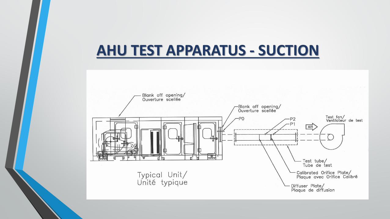
AHU TEST APPARATUS - SUCTION
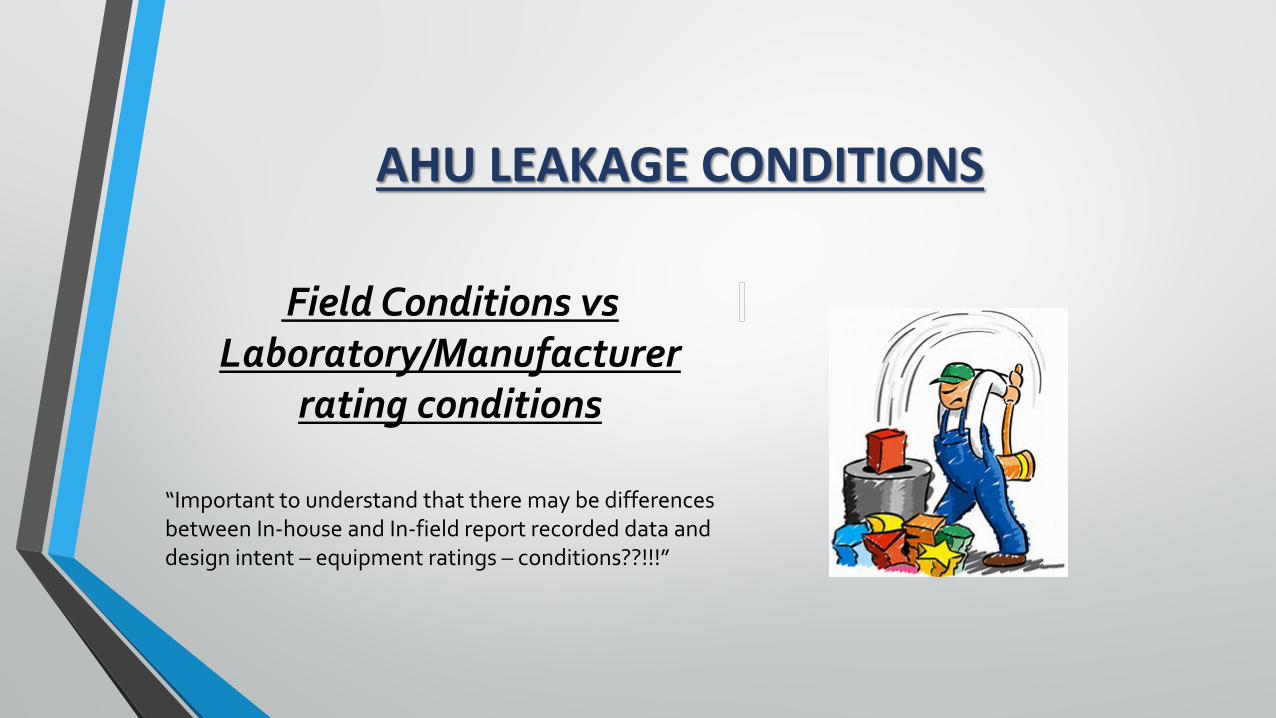
AHU LEAKAGE CONDITIONS
Field Conditions vs Laboratory/Manufacturer
rating conditions
“Important to understand that there may be differences between In-house and In-field report recorded data and design intent – equipment ratings – conditions??!!!”
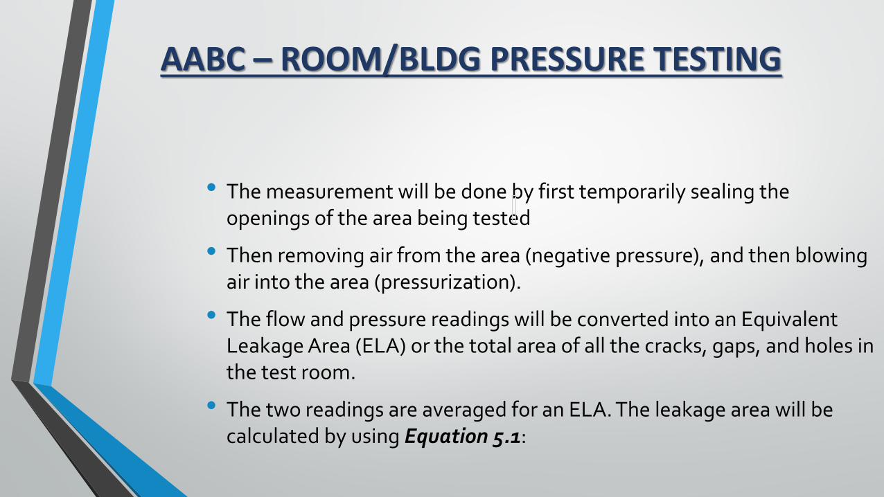
AABC – ROOM/BLDG PRESSURE TESTING
• The measurement will be done by first temporarily sealing the openings of the area being tested
• Then removing air from the area (negative pressure), and then blowing air into the area (pressurization).
• The flow and pressure readings will be converted into an Equivalent Leakage Area (ELA) or the total area of all the cracks, gaps, and holes in the test room.
• The two readings are averaged for an ELA. The leakage area will be calculated by using Equation 5.1:
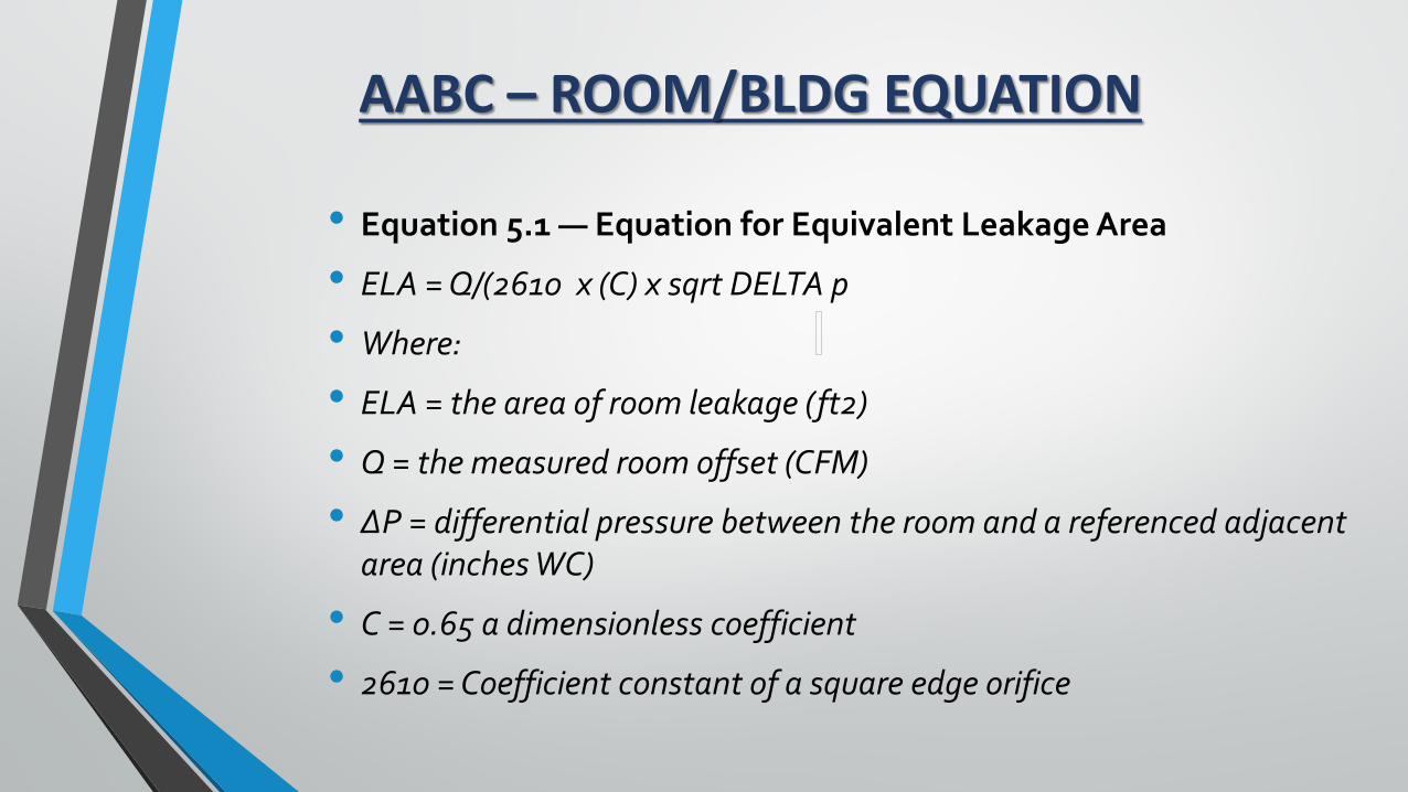
AABC – ROOM/BLDG EQUATION
• Equation 5.1 — Equation for Equivalent Leakage Area
• ELA = Q/(2610 x (C) x sqrt DELTA p
• Where:
• ELA = the area of room leakage (ft2)
• Q = the measured room offset (CFM)
• ΔP = differential pressure between the room and a referenced adjacent area (inches WC)
• C = 0.65 a dimensionless coefficient
• 2610 = Coefficient constant of a square edge orifice
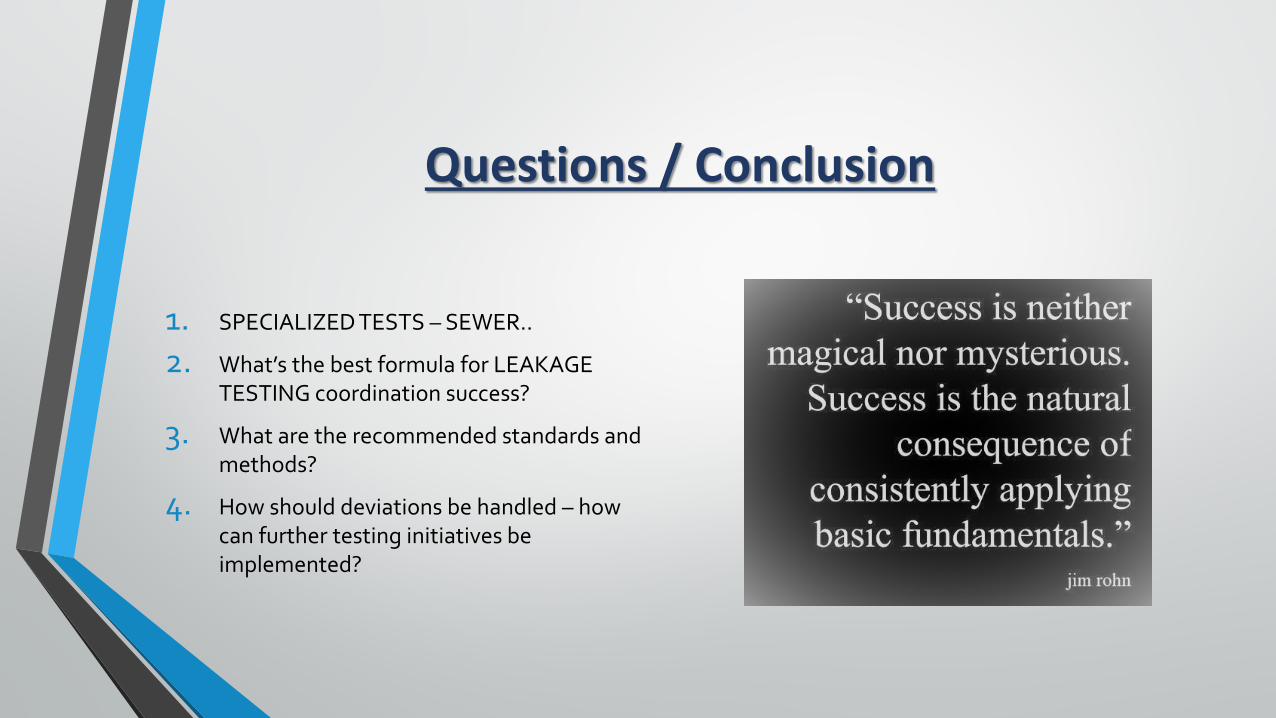
Questions / Conclusion
1. SPECIALIZED TESTS – SEWER..
2. What’s the best formula for LEAKAGE TESTING coordination success?
3. What are the recommended standards and methods?
4. How should deviations be handled – how can further testing initiatives be implemented?