a525 fermentation tank controller product bulletin
TRANSCRIPT

A525 Fermentation Tank Controller ProductBulletin
IntroductionThe A525 Fermentation Tank Controller controlsfermentation tanks for the processing of wine and otherfermented beverages. The controller maintains thetemperature level, the pump-over, and the oxygen andcarbon dioxide levels in the fermentation tank for theappropriate fermentation environment. The controllerincludes five relays to control the following features:• Cooling• User-provided alarms• Pump-over• Air supply valve (ASV)• Heating
Figure 1: A525 Fermentation Tank Controller
The controller's system status and setup informationdisplays on an LCD UI. The controller controls thetemperature of the fermentation tank according to thecontroller’s heat only, cool only, or heat and cool modes.The variable-frequency drive (VFD) interface manages thepump and the pump performs pump-over operations.Start and stop a pump-over with the BACnet network, aremote switch push button, or the Pump key.You can manually control the five controller relays usingthe OVERRIDE state. The controller includes five types ofalarm and three alarm actions. The controller includes anIP65 enclosure with holes in the enclosure base for walland surface mounting. You can order an optional DIN railmounting kit (part no. BKT524-1K).
Features and benefitsComplete control
Provides control of all aspects of the fermentationprocess including temperature control, pump-over, and air supply control.
Continous monitoring
Provides knowledge of tank conditions at alltimes with flexible remote monitoring and dataextraction.
Easy set up
Saves time and improves efficiency with easy toset up and use features and functions.
Plain language display
Features an easy to use alphanumeric display andmenu structure.
Customizable alarms
Offers product protection with alarms for hightemperatures, low temperatures, sensor failures,pump failures, and communications loss.
Easy integration
Reduces operating costs and improves energyefficiency through integration with HVACequipment for facility-wide environmental control.
LIT-12013101
2019-06-07
A525

ApplicationsYou can use the A525 Fermentation Tank Controller withfermentation tank system environments.
Important: Use the A525 Fermentation TankController only as an operating control. Wherefailure or malfunction of the A525 FermentationTank Controller could lead to personal injury orproperty damage to the controlled equipment orother property, additional precautions must bedesigned into the control system. Incorporate andmaintain other devices, such as supervisory or alarmsystems or safety or limit controls, intended to warnof or protect against failure or malfunction of theA525 Fermentation Tank Controller.Important: Utiliser ce A525 Fermentation TankController uniquement en tant que dispositif decontrôle de fonctionnement. Lorsqu'une défaillanceou un dysfonctionnement du A525 FermentationTank Controller risque de provoquer des blessuresou d'endommager l'équipement contrôlé ou unautre équipement, la conception du système decontrôle doit intégrer des dispositifs de protectionsupplémentaires. Veiller dans ce cas à intégrer defaçon permanente d'autres dispositifs, tels quedes systèmes de supervision ou d'alarme, ou desdispositifs de sécurité ou de limitation, ayant unefonction d'avertissement ou de protection en casde défaillance ou de dysfonctionnement du A525Fermentation Tank Controller.
UIThe controller’s system status and setup informationdisplays on an LCD UI with adjustable brightness. Thestatus indicator icons show the heating, cooling, pump-over, RUN/STOP, and alarm features and provide a visualindication of the system status and alarms. The Alarm,Pump, and RUN/STOP icons also function as keys.You can use these keys to respond to system alarms,manually start the pump, or manually stop the controller.Use the four touchpad keys to navigate the system, seedetailed system information, and change parametersettings. You can also use the touchpad keys to respondto system alarms.
System setupThe system setup settings define the system attributes,the hardware features, and the hard-wired componentsof the controller. To set up the controller for use withthe fermentation tank system, configure the followingsettings in the setup screens:• System state• Control mode• Date and time• Sn1 setup• VFD interface• Units• Keypad sound• Display brightness• BACnet
• System name• User passcode• Firmware update
Temperature controlThe A525 Fermentation Tank Controller controls thetemperature of the fermentation tank by opening andclosing the two valves that supply the hot and cold fluid tothe tank jacket.The TE-631AP-1 temperature sensor input defines theopening and closing requirements of the valve fortemperature control. The temperature sensor uses asingle setpoint and a single differential. The setpointrange is -25F° to 195F° (-32C° to 91C°). The differentialrange is 1F° to 15F° (1C° to 8C°).The cooling valve opens when the sensor temperatureis equal to the setpoint plus the differential. The coolingvalve closes at the setpoint. The heating valve opens whenthe sensor temperature is equal to the setpoint minus thedifferential. The heating valve closes at the setpoint.The A525 Fermentation Tank Controller uses three modesof operation that define the temperature control:• Heat only• Cool only• Heat and cool
Pump-over controlThe VFD interface manages the pump. The VFD controlsthe speed of the pump motor and the pump performspump-over operations. You can start and stop a pump-over in the following ways:• BACnet• Remote switch• Pump icon or key
VFD interface modesUse the Modbus® or direct wire modes to connect theA525 Fermentation Tank Controller to the VFD.
ModbusThe controller uses the Modbus protocol to communicatewith the VFD. This is an optional feature. The controllerand the VFD share a one-to-one connection.
Direct wireThe controller supplies the enable signal to the VFD andprovides the speed reference as an option. Optionally, youcan set the speed at the controller or at the VFD. Whenyou set the speed at the VFD, you can connect an outputof the drive to the controller, which provides the speedindication to the controller.
OverrideYou can manually control the five controller relays usingthe OVERRIDE state. You can enter the OVERRIDE statefrom the RUN state and manually turn on and off the
A525 Fermentation Tank Controller Product Bulletin2

heat, cool, ASV, pump, and alarm relays. When you enterthe OVERRIDE state, the controller preserves the presentRUN state settings of the relays.In OVERRIDE, the relay settings you define function solelyin the OVERIDE state. When you leave the OVERRIDE state,the relays revert to their previous RUN state settings.
AlarmsThe controller includes the following alarm types and trueconditions:
Sn1 high-temperature:
The temperature at Sn1 is greater than thedefined high-temperature alarm value for aperiod of time that is equal to or greater than thealarm delay.
Sn1 low-temperature:
The temperature at Sn1 is lower than the definedlow-temperature alarm value for a period of timethat is equal to or greater than the alarm delay.
Sn1 sensor failure:
Sn1 is in a state of failure.
Pump failure:
The pump is in a state of failure based on thecurrent sensor input.
VFD comm loss:
The system loses communication with the VFD.
Alarm actionsIf an alarm condition occurs, the controller takes thefollowing alarm actions:• Buzzer: If you enable the buzzer, the buzzer energizes
upon alarm.• Alarm relay: The alarm relay energizes when any
alarm condition is true. The alarm relay de-energizeswhen you acknowledge the alarm locally or when thecondition is no longer true.
• Alarm icon: The user interface lights the alarmicon when any alarm condition is true or requiresacknowledgement.
FileUse a USB drive to automatically import and export datafrom the controller.
DimensionsThe following figures show the dimensions of the A525Fermentation Tank Controller:
Figure 2: A525 Fermentation Tank Controller frontpanel with dimensions in millimeters (inches)
Figure 3: A525 Fermentation Tank Controller rearpanel with mounting hole dimensions in millimeters(inches)
Figure 4: A525 Fermentation Tank Controller side viewwith dimensions in millimeters (inches)
Figure 5: A525 Fermentation Tank Controller top viewwith dimensions in millimeters (inches)
A525 Fermentation Tank Controller Product Bulletin 3

Ordering informationThe following two tables contain ordering information forthe A525 Fermentation Tank Controller and accessories.For more information about these products, contact thenearest Johnson Controls® or PENN® distributor or salesrepresentative.Table 1: A525 Fermentation Tank Controller selectionchart
Product code DescriptionA525AETR-0000C Wall mount electronic fermentation
tank controller with two sensorinputs and five output relays.
TE-631AP-1 1K ohm nickel temperature sensor(6 in. well probe assembly bulb)with thermoplastic conduit box andthermowell holder included.See Table 8 and refer to the TE-6300Series Temperature Sensors ProductBulletin (LIT-216320) for moreinformation about the TE-631AP-1sensor.You can use any TE-631xx-xtemperature sensor with the A525Fermentation Tank Controller. TheTE-631xx-x temperature sensors areavailable to order separately.
Table 2: A525 Fermentation Tank Controlleraccessories
Product code DescriptionBKT287-1R 305 mm (12 in.) section of 35 mm
DIN railBKT524-1K Bracket kit for mounting A525
Fermentation Tank Controller to 35mm DIN rail. Includes five mountingscrews
Repair informationDo not attempt to repair the A525 FermentationTank Controller. In case of a defective or improperlyfunctioning A525 Fermentation Tank Controller, contactyour nearest authorized Johnson Controls or PENNdistributor or sales representative.When contacting your Johnson Controls or PENNdistributor, check the model number of the controller. Youcan find the model number on the label inside the coverof the controller.
Relay electrical ratingsTable 3 to Table 7 provide the electrical ratings for thecontrol relays in the controller.Table 3: Single-pole, single-throw (SPST) coolingsolenoid relay electrical ratingsAgency and file UL 60730 EN
60730Applied ACvoltage at 50/60Hz
24 VAC 120 VAC 240 VAC 240 VAC
Pilot duty VA(N.O.)
125 VA at 24 VAC—240 VAC
Number of cycles 100,000
Table 4: SPST heating solenoid relay electrical ratingsAgency and file UL 60730 EN
60730Applied ACvoltage at 50/60Hz
24 VAC 120 VAC 240 VAC 240 VAC
Pilot duty VA(N.O.)
125 VA at 24 VAC—240 VAC
Number of cycles 100,000
Table 5: Single-pole, double-throw (SPDT) alarm relayelectrical ratingsAgency and file UL 60730 EN
60730Applied AC voltageat 50/60 Hz
24 VAC 120 VAC 240 VAC 240 VAC
Full load amperesN.O. (N.C.)
n/a 9.8 A 4.9 A 4.9 A
Locked rotoramperes N.O.(N.C.)
n/a 58.8 A 29.4 A 29.4 A
Resistive amperesN.O. (N.C.)
10 A
Pilot duty VA N.O.(N.C.)
125 VA at 24 VAC—240 VAC
Number of cycles 30,000
Table 6: SPST pump-over relay electrical ratingsAgency and file UL 60730 EN
60730Applied ACvoltage at 50/60Hz
24 VAC 120 VAC 240 VAC 240 VAC
Pilot duty VA(N.O.)
125 VA at 24 VAC—240 VAC
Number of cycles 30,000
A525 Fermentation Tank Controller Product Bulletin4
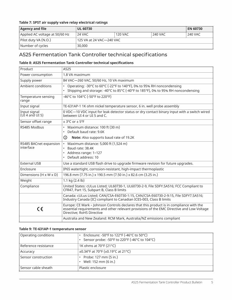
Table 7: SPST air supply valve relay electrical ratings
Agency and file UL 60730 EN 60730Applied AC voltage at 50/60 Hz 24 VAC 120 VAC 240 VAC 240 VACPilot duty VA (N.O.) 125 VA at 24 VAC—240 VACNumber of cycles 30,000
A525 Fermentation Tank Controller technical specificationsTable 8: A525 Fermentation Tank Controller technical specifications
Product A525Power consumption 1.8 VA maximumSupply power 84 VAC—260 VAC, 50/60 Hz, 10 VA maximumAmbient conditions • Operating: -30°C to 60°C (-22°F to 140°F), 0% to 95% RH noncondensing
• Shipping and storage: -40°C to 85°C (-40°F to 185°F), 0% to 95% RH noncondensingTemperature sensingrange
-46°C to 104°C (-50°F to 220°F)
Input signal TE-631AP-1 1K ohm nickel temperature sensor, 6 in. well probe assemblyInput signal(UI 4 and UI 5)
0 VDC—10 VDC input for leak detector status or dry contact binary input with a switch wiredbetween UI 4 or UI 5 and C.
Sensor offset range ± 3ºC or ± 5ºFRS485 Modbus • Maximum distance: 100 ft (30 m)
• Default baud rate: 9.6KNote: Also supports baud rate of 19.2K
RS485 BACnet expansioninterface
• Maximum distance: 5,000 ft (1,524 m)• Baud rate: 38.4K• Address range: 1–127• Default address: 10
External USB Use a standard USB flash drive to upgrade firmware revision for future upgrades.Enclosure IP65 watertight, corrosion-resistant, high-impact thermoplasticDimensions (H x W x D) 196.8 mm (7.75 in.) x 190.5 mm (7.50 in.) x 82.6 cm (3.25 in.)Weight 1.1 kg (2.4 lb)Compliance United States: cULus Listed; UL60730-1, UL60730-2-9, File SDFY.SA516; FCC Compliant to
CFR47, Part 15, Subpart B, Class B limitsCanada: cULus Listed; CAN/CSA-E60730-1:15, CAN/CSA-E60730-2-9:15, File SDFY7.SA516;Industry Canada (IC) compliant to Canadian ICES-003, Class B limitsEurope: CE Mark – Johnson Controls declares that this product is in compliance with theessential requirements and other relevant provisions of the EMC Directive and Low VoltageDirective; RoHS DirectiveAustralia and New Zealand: RCM Mark, Australia/NZ emissions compliant
Table 9: TE-631AP-1 temperature sensor
Operating conditions • Enclosure: -50°F to 122°F (-46°C to 50°C)• Sensor probe: -50°F to 220°F (-46°C to 104°C)
Reference resistance 1K ohms at 70°F (21°C)Accuracy ±0.34°F at 70°F (±0.19°C at 21°C)Sensor construction • Probe: 127 mm (5 in.)
• Well: 152 mm (6 in.)Sensor cable sheath Plastic enclosure
A525 Fermentation Tank Controller Product Bulletin 5

North American emissions compliance
United StatesThis equipment has been tested and found to comply with the limits for a Class B digital device, pursuant to Part 15 ofthe FCC Rules. These limits are designed to provide reasonable protection against harmful interference in a residentialinstallation. This equipment generates, uses and can radiate radio frequency energy and, if not installed and usedin accordance with the instructions, may cause harmful interference to radio communications. However, there is noguarantee that interference will not occur in a particular installation. If this equipment does cause harmful interferenceto radio or television reception, which can be determined by turning the equipment off and on, the user is encouraged totry to correct the interference by one or more of the following measures:
• Reorient or relocate the receiving antenna.• Increase the separation between the equipment and receiver.• Connect the equipment into an outlet on a circuit different from that to which the receiver is connected.• Consult the dealer or an experienced radio/TV technician for help.
CanadaThis Class (B) digital apparatus meets all the requirements of the Canadian Interference-Causing Equipment Regulations.Cet appareil numérique de la Classe (B) respecte toutes les exigences du Règlement sur le matériel brouilleur du Canada.
© 2019 Johnson Controls. All rights reserved. All specifications and other information shown were current as of document revision andare subject to change without notice.
www.penncontrols.com