a2.37 transformer reliability survey
TRANSCRIPT

Transformer Reliability SurveyTutorial of CIGRÉ WG A2.37
Convener: Stefan Tenbohlen, Germany
1
Transformer Reliability Survey – Tutorial of CIGRÉ WG A2.37
05.04.2011
AIM• CIGRE (International Council on Large Electric Systems) is one of the leading
worldwide Organizations on Electric Power Systems, covering their technical, economic, environmental, organisational and regulatory aspects.
> Facilitate the exchange of information between engineering personnel and specialists in all countries and develop knowledge in power systems.
> Add value to the knowledge and information exchanged by synthesizing state-of-the-art world practices.
> Make managers, decision-makers and regulators aware of the synthesis of CIGRE's work, in the area of electric power.
More specifically, issues related to planning and operation of power systems, as well as design, construction, maintenance and disposal of HV equipment and plants are at the core of CIGRE's mission. Problems related to protection of power systems, telecontrol, telecommunication equipment and information systems are also part of CIGRE's area of concern.
Transformer Reliability Survey – Tutorial of CIGRÉ WG A2.37
05.04.2011
Cigre Study Committees• A1 Rotating Electrical Machines• A2 Transformers• A3 High Voltage Equipment• B1 Insulated Cables• B2 Overhead Lines• B3 Substations• B4 HVDC and Power Electronics• B5 Protection and Automation• C1 System Development and Economics• C2 System Operation and Control• C3 System Environmental Performance• C4 System Technical Performance• C5 Electricity Markets and Regulation• C6 Distribution Systems and Dispersed Generation• D1 Materials and Emerging Test Techniques• D2 Information Systems and Telecommunication

Transformer Reliability SurveyTutorial of CIGRÉ WG A2.37
Convener: Stefan Tenbohlen, Germany
4
Name Company/Institute CountryStefan Tenbohlen (Conv.) Universität Stuttgart GermanyJanine Jagers (Secr.) Eskom South AfricaJohannes Gebauer Maschinenfabrik Reinhausen GermanyPascal Müller EWZ SwitzerlandJohn Lapworth Doble United KingdomShirasaka Yukiyasu Hitachi JapanBhavin Desai EPRI USAGilson Bastos Furnas BrazilJitka Fuhr BKW SwitzerlandTakehisa Sakai J Power(Japanese Utility) JapanMichael Krüger Omicron Austria Claude Rajotte Hydro Quebec CanadaFarzaneh Vahidi Universität Stuttgart GermanyBrendan Diggin ESBI IrelandPiotr Manski PSW Operator SA PolandAntun Mikulecky Koncar - Electr. Eng. Institute Croatia
Transformer Reliability Survey – Tutorial of CIGRÉ WG A2.37
Outline
5
1. MOTIVATION AND TERMS OF REFERENCE2. THEORETICAL BACKGROUND AND DEFINITIONS3. DESCRIPTION OF EXISTING TRANSFORMER RELIABILITY
SURVEYS4. DEVELOPED METHODOLOGY FOR STANDARDIZED
FAILURE DATA COLLECTION 5. RESULTS OF PERFORMED RELIABILITY SURVEY6. CONCLUSION AND RECOMMENDATION

Transformer Reliability Survey – Tutorial of CIGRÉ WG A2.37
MotivationTransformer Reliability Survey
Accurate information about service experience of high voltage equipment is of significant value for both electric utilities and for manufacturers,
It helps the manufacturers to improve their products, It provides important inputs for the utilities when buying equipment, when
organizing maintenance and when benchmarking their performance,
Statistical analysis of the past failure data can display useful features with respect to the future failure behavior,
Equipment reliability data are also required when assessing the overall reliability of an electric power system,
Furthermore, international standards applicable to high voltage equipment are being improved on the basis of service experience and reliability data.
Total Cost of Ownership
=First
Price+
Cost of
Losses
Cost of not
Running+
Transformer Reliability Survey – Tutorial of CIGRÉ WG A2.37
Life Assessment Methodologies
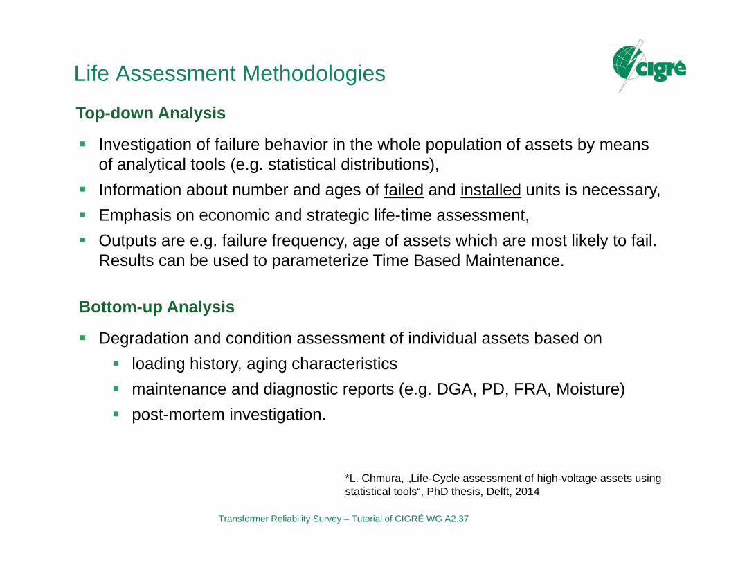
Investigation of failure behavior in the whole population of assets by means of analytical tools (e.g. statistical distributions),
Information about number and ages of failed and installed units is necessary, Emphasis on economic and strategic life-time assessment, Outputs are e.g. failure frequency, age of assets which are most likely to fail.
Results can be used to parameterize Time Based Maintenance.
Top-down Analysis
Degradation and condition assessment of individual assets based on loading history, aging characteristics maintenance and diagnostic reports (e.g. DGA, PD, FRA, Moisture) post-mortem investigation.
Bottom-up Analysis
*L. Chmura, „Life-Cycle assessment of high-voltage assets usingstatistical tools“, PhD thesis, Delft, 2014

Transformer Reliability Survey – Tutorial of CIGRÉ WG A2.37
Terms of Reference, WG A2.37 Transformer Reliability Survey
The current CIGRE reliability statistic is/was based on failure data from 1968 to 1978! * Several approaches failed because of restriction to data access
Terms of Reference: Review all existing national surveys and study different practices
(data collection, compilation, etc.) Conducting a new international survey on transformer failures, and
proposing a uniform way of collecting, compiling and presenting data. Compiling and analysing the collected data, and interpreting the
results (calculation of failure rates, classification into failure location, failure causes and failure modes) Recommendations
*A. Bossi, e. al, „An international survey on failures in large power transformers in service“ Cigré Electra No.88, 1983.

Transformer Reliability Survey – Tutorial of CIGRÉ WG A2.37
THEORETICAL BACKGROUND AND DEFINITIONS
9

Transformer Reliability Survey – Tutorial of CIGRÉ WG A2.37
Definitions
10
Any situation which requires the equipment to be removed from service to be repaired (Cigre WG A2.18, 2003).
The systems operator’s focus would be on the impact on the system, ranking failure in terms of system reliability, whereas the plant specialist would rank it in terms of what remedial action would be required to restore equipment functionality
Failure
Ability of an item to perform a required function under given conditions for a given time interval (IEC, 1986)
Probability that the equipment will remain in service without a failure occurring (Cigre WG A2.18, 2003).
Reliability

Transformer Reliability Survey – Tutorial of CIGRÉ WG A2.37
Failure Rate
11
iTiNTNTNinnn
...2211
...21%100
ni is the number of failures by i-th populationNi is the number of transformers of i-th populationTi is the reference period of i-th population
TiNNNinnn
)...21(
...21%100
ni is the number of failures in the i-th yearNi is the number of transformers operating in the i-th yearT is the reference period (one year)
Failure rate of a single population:
Failure rate of combined population:
Number of failures divided by the number of transformers in service over a period of time.
Transformer Reliability Survey – Tutorial of CIGRÉ WG A2.37
Definitions
12
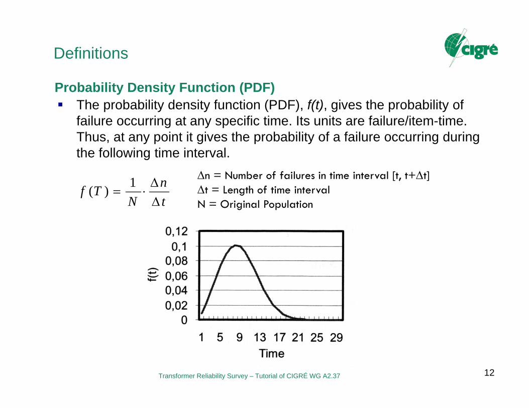
The probability density function (PDF), f(t), gives the probability of failure occurring at any specific time. Its units are failure/item-time. Thus, at any point it gives the probability of a failure occurring during the following time interval.
Probability Density Function (PDF)
tn
NTf
1)(n = Number of failures in time interval [t, t+t]t = Length of time intervalN = Original Population

Transformer Reliability Survey – Tutorial of CIGRÉ WG A2.37
Definitions
13
The failure distribution function is a cumulative distribution functionand gives the cumulative probability of failure. It thus represents the probability that a failure has occurred on or before a certain time.
Failure Distribution Function (CDF)
ni = Number of failures up to time tN = Original PopulationN
tndttftF i
t )(
)()(0
Transformer Reliability Survey – Tutorial of CIGRÉ WG A2.37
Definitions
14
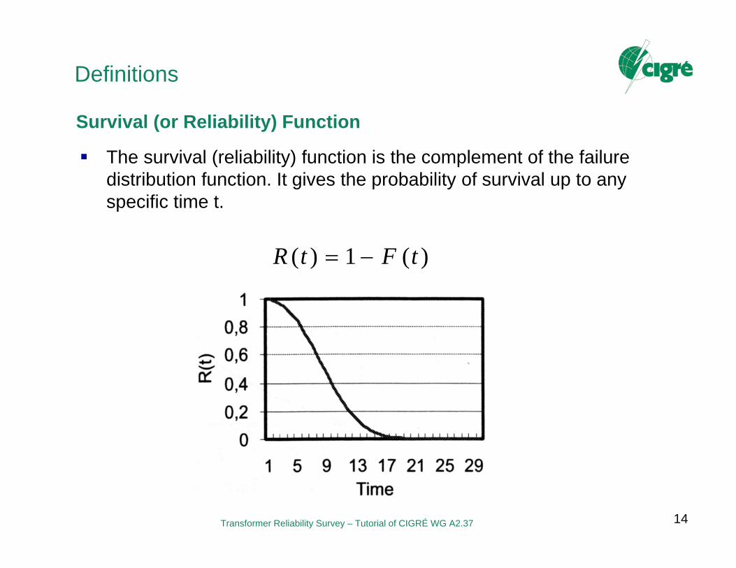
The survival (reliability) function is the complement of the failure distribution function. It gives the probability of survival up to any specific time t.
Survival (or Reliability) Function
)(1)( tFtR

Transformer Reliability Survey – Tutorial of CIGRÉ WG A2.37
Definitions
15
Hazard Function
)()()(
)(1)(
tRtf
ttn
tNth
n(t) = Number of failures in time interval [t, t+t]t = Length of time intervalN(t) = Population surviving at time t
h(t) is the instantaneous failure rate at age t, that is, in the short time t from t to t+t, a proportion t·h(t) of the population that reached age t fails.
Transformer Reliability Survey – Tutorial of CIGRÉ WG A2.37
Definitions
16
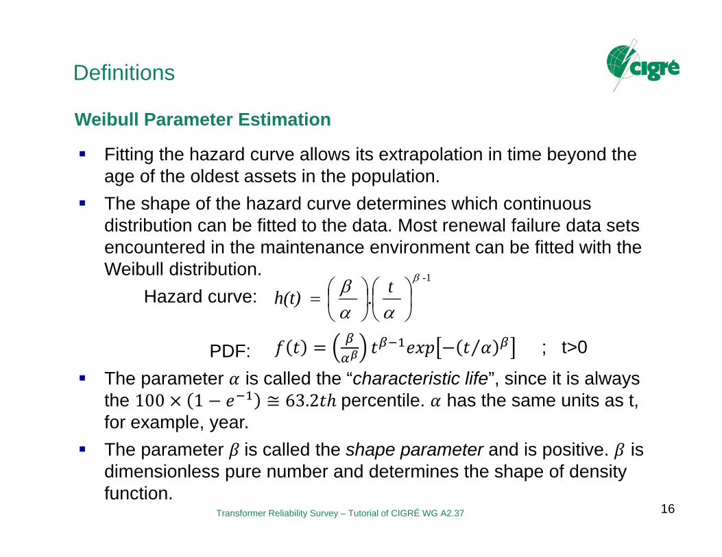
Weibull Parameter Estimation
⁄ ; t>0
Fitting the hazard curve allows its extrapolation in time beyond the age of the oldest assets in the population.
The shape of the hazard curve determines which continuous distribution can be fitted to the data. Most renewal failure data sets encountered in the maintenance environment can be fitted with the Weibull distribution.
Hazard curve:
PDF: The parameter is called the “characteristic life”, since it is always
the 100 1 ≅ 63.2 percentile. has the same units as t, for example, year.
The parameter is called the shape parameter and is positive. is dimensionless pure number and determines the shape of density function.
1-
.
th(t)

Transformer Reliability Survey – Tutorial of CIGRÉ WG A2.37
Definitions
17
Weibull Parameter Estimation
⁄ ; t>0
Hazard curve:
PDF: The parameter is called the “characteristic life”, since it is always
the 100 1 ≅ 63.2 percentile. has the same units as t, for example, year.
The parameter is called the shape parameter and is positive. is dimensionless pure number and determines the shape of density function.
1-
.
th(t)
Transformer Reliability Survey – Tutorial of CIGRÉ WG A2.37
Definitions
18
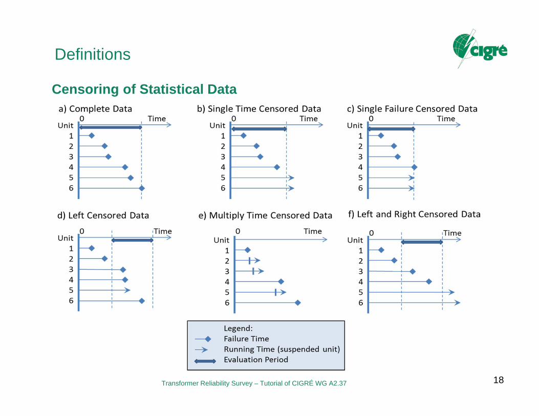
Censoring of Statistical Data
Transformer Reliability Survey – Tutorial of CIGRÉ WG A2.37
DESCRIPTION OF EXISTING TRANSFORMER RELIABILITY SURVEYS
Canada Germany
19
Transformer Reliability Survey – Tutorial of CIGRÉ WG A2.37
Canadian Electricity Association
20
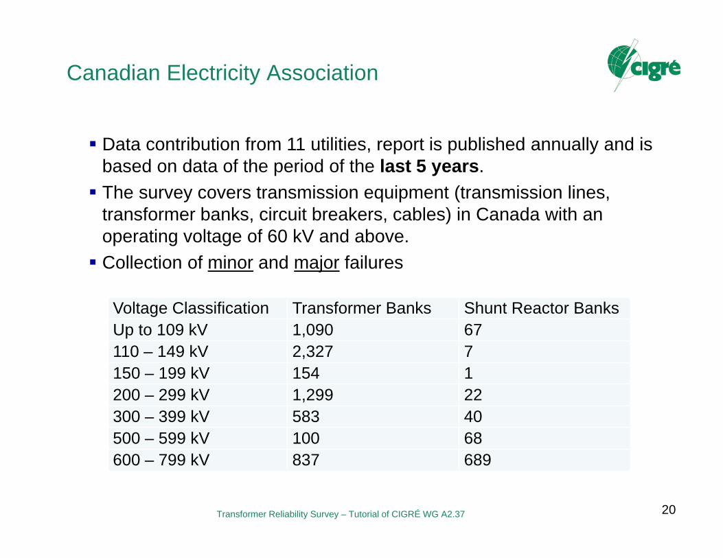
Data contribution from 11 utilities, report is published annually and isbased on data of the period of the last 5 years. The survey covers transmission equipment (transmission lines,
transformer banks, circuit breakers, cables) in Canada with an operating voltage of 60 kV and above. Collection of minor and major failures
Voltage Classification Transformer Banks Shunt Reactor BanksUp to 109 kV 1,090 67110 – 149 kV 2,327 7150 – 199 kV 154 1200 – 299 kV 1,299 22300 – 399 kV 583 40500 – 599 kV 100 68600 – 799 kV 837 689

Transformer Reliability Survey – Tutorial of CIGRÉ WG A2.37
Canadian Electricity AssociationPower Transformers
21
Transformer Reliability Survey – Tutorial of CIGRÉ WG A2.37
German FNN-StatistikObjective
22
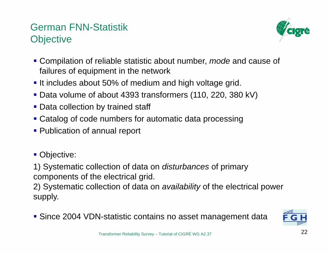
Compilation of reliable statistic about number, mode and cause of failures of equipment in the network It includes about 50% of medium and high voltage grid. Data volume of about 4393 transformers (110, 220, 380 kV) Data collection by trained staff Catalog of code numbers for automatic data processing Publication of annual report
Objective:1) Systematic collection of data on disturbances of primarycomponents of the electrical grid. 2) Systematic collection of data on availability of the electrical power supply.
Since 2004 VDN-statistic contains no asset management data
Transformer Reliability Survey – Tutorial of CIGRÉ WG A2.37
Recording Scheme (1/2)
2323
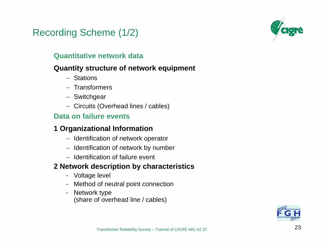
Quantitative network dataQuantity structure of network equipment
Stations Transformers Switchgear Circuits (Overhead lines / cables)
Data on failure events1 Organizational Information
Identification of network operator Identification of network by number Identification of failure event
2 Network description by characteristics- Voltage level- Method of neutral point connection- Network type
(share of overhead line / cables)
Transformer Reliability Survey – Tutorial of CIGRÉ WG A2.37
Recording Scheme (2/2)
24
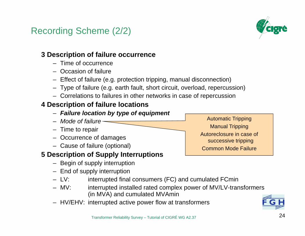
3 Description of failure occurrence– Time of occurrence– Occasion of failure– Effect of failure (e.g. protection tripping, manual disconnection)– Type of failure (e.g. earth fault, short circuit, overload, repercussion)– Correlations to failures in other networks in case of repercussion
4 Description of failure locations– Failure location by type of equipment– Mode of failure– Time to repair– Occurrence of damages– Cause of failure (optional)
5 Description of Supply Interruptions– Begin of supply interruption – End of supply interruption– LV: interrupted final consumers (FC) and cumulated FCmin– MV: interrupted installed rated complex power of MV/LV-transformers
(in MVA) and cumulated MVAmin– HV/EHV: interrupted active power flow at transformers
24
Automatic TrippingManual Tripping
Autoreclosure in case of successive tripping
Common Mode Failure
Transformer Reliability Survey – Tutorial of CIGRÉ WG A2.37
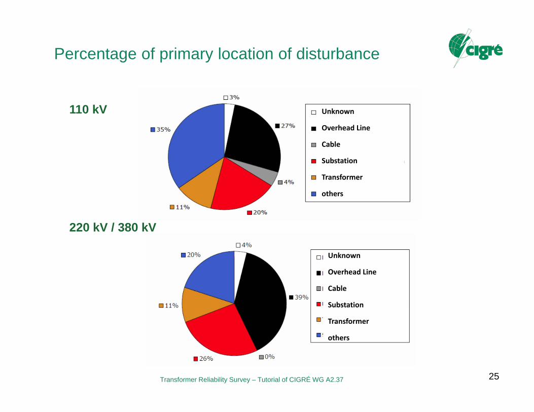
Percentage of primary location of disturbance
25
110 kV
220 kV / 380 kV
Unknown
Overhead Line
Cable
Substation
Transformer
others
Unknown
Overhead Line
Cable
Substation
Transformer
others

Transformer Reliability Survey – Tutorial of CIGRÉ WG A2.37
Number of disturbances per 100 transformers
26
110 kVwith failure
0.31 %
220/380 kVwith failure
0.64 %
Disturbances per 100
transformers
Without failure
With failure
Failure Rate 2004:

Transformer Reliability Survey – Tutorial of CIGRÉ WG A2.37
Conclusion on German FNN-Statistic
27
Focus on network operation Reliability of power supply For Asset Management not detailed enough,
no information about– Type and age of equipment,– Location within transformer (winding, bushing, etc.)– Causes of failure (only deficiency, system event, environmental)– Loading, operational condition
27
Transformer Reliability Survey – Tutorial of CIGRÉ WG A2.37
STANDARDIZED FAILURE DATA COLLECTION
28
Transformer Reliability Survey – Tutorial of CIGRÉ WG A2.37
Motivation for CIGRE Questionnaire
29
The main objective of the countrywide surveys is the systematic collection of data on the availability and disturbances of the electrical power supply, with emphasis on the frequency, duration and extent of the interruptions.
Detailed statistics about the failure location in the respective equipment, failure cause or mode and repair activities are normally not included.
The benefit of these statistics with respect to asset management is therefore limited.
Different definitions and information content constrain forming a coherent database from individual sources.
Therefore data collection is extended to utility data by means of a questionnaire.
www.uni-stuttgart.de/ieh/wga237.html
See Cigre A2-Website!

Transformer Reliability Survey – Tutorial of CIGRÉ WG A2.37
Definition of Major Failure
30
Any situation which requires the equipment to be removed from service for a period longer than 7 days for investigation, remedial work or replacement is a major failure.
Where repairs are required, these involve major remedial work, often requiring the transformer to be removed from its plinth and returned to the factory.
A major failure would require at least the opening of the tank, including the tap changer tank or an exchange of bushings.
Also a reliable indication that the condition of the transformer prevents a safe operation should be counted as a major failure if remedial work (longer than 7 days) is needed for restoring original service capability (e.g. detection of strong PDs).
Transformer Reliability Survey – Tutorial of CIGRÉ WG A2.37
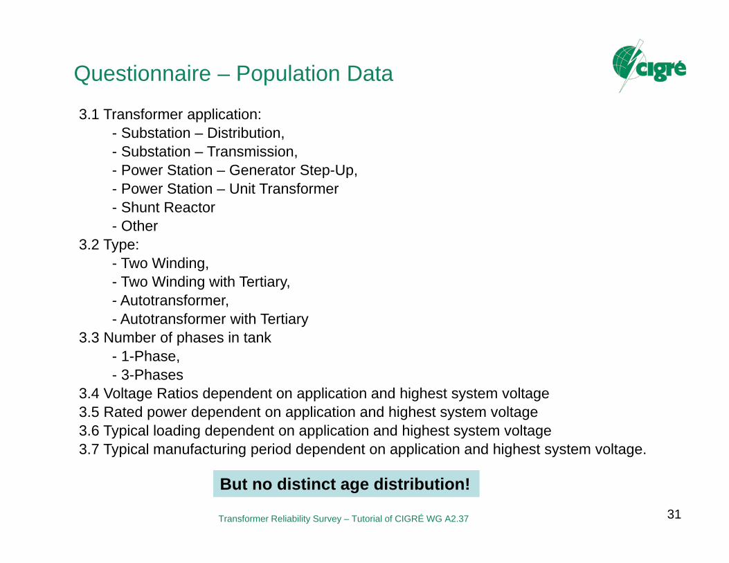
Questionnaire – Population Data
31
3.1 Transformer application: - Substation – Distribution, - Substation – Transmission, - Power Station – Generator Step-Up, - Power Station – Unit Transformer- Shunt Reactor- Other
3.2 Type:- Two Winding, - Two Winding with Tertiary, - Autotransformer, - Autotransformer with Tertiary
3.3 Number of phases in tank- 1-Phase, - 3-Phases
3.4 Voltage Ratios dependent on application and highest system voltage3.5 Rated power dependent on application and highest system voltage3.6 Typical loading dependent on application and highest system voltage3.7 Typical manufacturing period dependent on application and highest system voltage.
But no distinct age distribution!
Transformer Reliability Survey – Tutorial of CIGRÉ WG A2.37
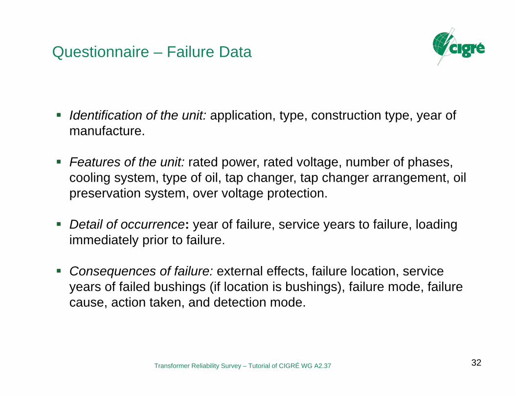
Questionnaire – Failure Data
32
Identification of the unit: application, type, construction type, year of manufacture.
Features of the unit: rated power, rated voltage, number of phases, cooling system, type of oil, tap changer, tap changer arrangement, oil preservation system, over voltage protection.
Detail of occurrence: year of failure, service years to failure, loading immediately prior to failure.
Consequences of failure: external effects, failure location, service years of failed bushings (if location is bushings), failure mode, failure cause, action taken, and detection mode.
Transformer Reliability Survey – Tutorial of CIGRÉ WG A2.37
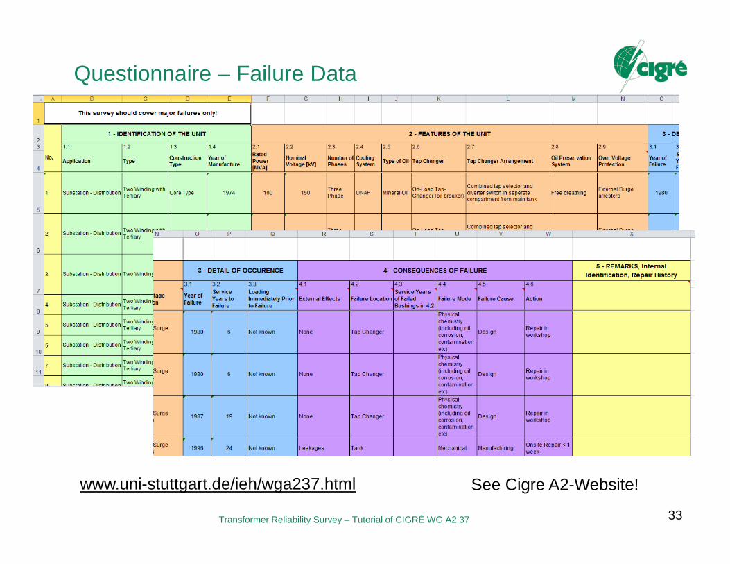
Questionnaire – Failure Data
33
www.uni-stuttgart.de/ieh/wga237.html See Cigre A2-Website!

Transformer Reliability Survey – Tutorial of CIGRÉ WG A2.37
Questionnaire – Failure Data
34
Answers are standardized by means of a pull-down menus
Confidentiality: Origin of data is only known to collector and convenor Within WG data are handled anonymously Outside WG only consolidated data will be presented

Transformer Reliability Survey – Tutorial of CIGRÉ WG A2.37
RESULTS OF RELIABILITY SURVEY
Investigated Population Failure Rate
35
Transformer Reliability Survey – Tutorial of CIGRÉ WG A2.37
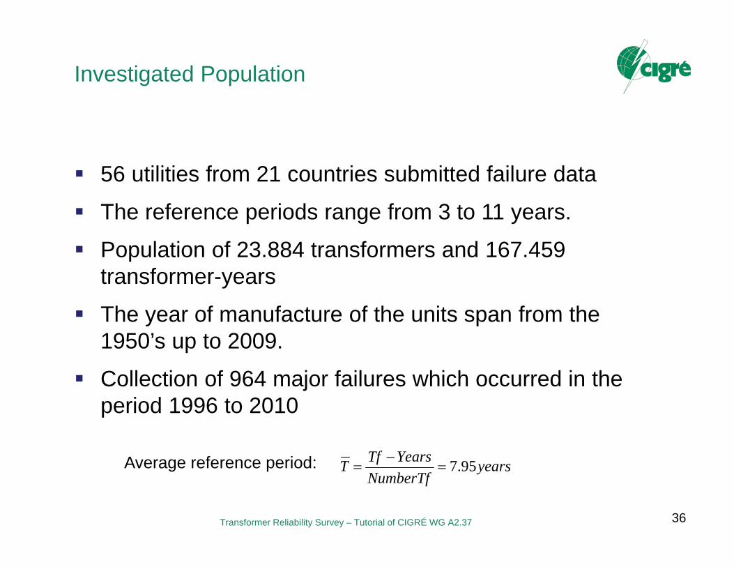
Investigated Population
56 utilities from 21 countries submitted failure data
The reference periods range from 3 to 11 years.
Population of 23.884 transformers and 167.459 transformer-years
The year of manufacture of the units span from the 1950’s up to 2009.
Collection of 964 major failures which occurred in the period 1996 to 2010
Average reference period: yearsNumberTf
YearsTfT 95.7
36

Transformer Reliability Survey – Tutorial of CIGRÉ WG A2.37
Investigated Populationdependent on Voltage Class and Origin
69< U <100 100< U <200 200< U <300
300< U <500 500< U <700 U >700

Transformer Reliability Survey – Tutorial of CIGRÉ WG A2.37
Investigated Population dependent on Application
38
Substation Transformers
Generator Step-Up Transformers
POPULATION INFORMATION
HIGHEST SYSTEM VOLTAGE [kV]
69 ≤ kV < 100 100 ≤ kV < 200 200 ≤ kV < 300 300 ≤ kV < 500 500 ≤ kV < 700 kV ≥ 700 All
Number of Utilities 10 38 31 27 3 4 51
Number of Transformers
2.962 10.932 4.272 3.233 434 348 22.181
Transformer-Years 15.267 64.718 37.017 25.305 4.774 2.991 150.072
POPULATION INFORMATION
HIGHEST SYSTEM VOLTAGE [kV]
69 ≤ kV < 100 100 ≤ kV < 200 200 ≤ kV < 300 300 ≤ kV < 500 500 ≤ kV < 700 kV ≥ 700 All
Number of Utilities
3 17 20 13 1 1 26
Number of Transformers
14 320 455 673 167 74 1,703
Transformer-Years
153 3,278 4,639 6,740 1,837 740 17,387
yearsNumberTf
YearsTfT 2.10
yearsNumberTf
YearsTfT 8.6

Transformer Reliability Survey – Tutorial of CIGRÉ WG A2.37
Investigated Population dependent on Application
39
Substation Transformers
Generator Step-Up Transformers
0%
10%
20%
30%
40%
50%Number of TransformersTransformer-Year
0%
10%
20%
30%
40%
50%Number of Transformers
Transformer-Year
Transformer Reliability Survey – Tutorial of CIGRÉ WG A2.37
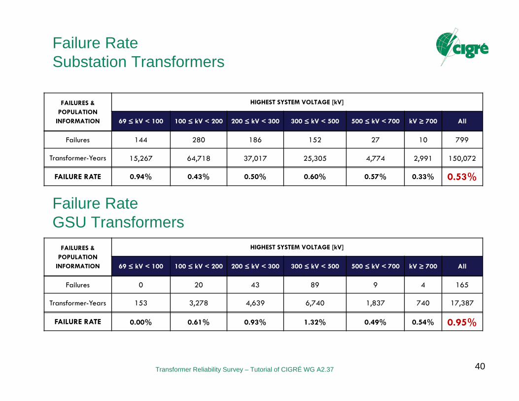
Failure Rate Substation Transformers
40
FAILURES & POPULATION
INFORMATION
HIGHEST SYSTEM VOLTAGE [kV]
69 ≤ kV < 100 100 ≤ kV < 200 200 ≤ kV < 300 300 ≤ kV < 500 500 ≤ kV < 700 kV ≥ 700 All
Failures 144 280 186 152 27 10 799
Transformer-Years 15,267 64,718 37,017 25,305 4,774 2,991 150,072
FAILURE RATE 0.94% 0.43% 0.50% 0.60% 0.57% 0.33% 0.53%
FAILURES & POPULATION
INFORMATION
HIGHEST SYSTEM VOLTAGE [kV]
69 ≤ kV < 100 100 ≤ kV < 200 200 ≤ kV < 300 300 ≤ kV < 500 500 ≤ kV < 700 kV ≥ 700 All
Failures 0 20 43 89 9 4 165
Transformer-Years 153 3,278 4,639 6,740 1,837 740 17,387
FAILURE RATE 0.00% 0.61% 0.93% 1.32% 0.49% 0.54% 0.95%
Failure Rate GSU Transformers

Transformer Reliability Survey – Tutorial of CIGRÉ WG A2.37
Failure Rates from other Surveys
41
SURVEYAPPLICATION/
CLASSIFICATION
FAILUREPERIOD
MANUFACTURING
PERIOD
FAILURERATE (%)
SOURCE
CigréInternationalSurvey
All voltage levels(60kV-700kV)
1968 - 1978 Pre 1978 2 [Bossi, 1983]
United Kingdom All voltage levels Pre 1987 Pre 1987 < 2 [Allan, 1987]
United KingdomGenerator Step-Up,Major failures
1974 - 1995 Pre 1995* 1.2 [Hall, 2006]
ZTZ ServiceDatabase,Ukraine
Generator Step-Up &Transmission Ratedpower ≥ 100MVA,
2000 - 2005 Pre 2005 1 - 2 [Sokolov, 2005-2]
US-NGRID, UnitedStates
Distribution 115kV,69kV & <69kV
- - 0.35 - 0.8 [Prout , 2003]
Hydro Quebec,Canada
All voltage categories,major failures
- - < 0.5 [Foata, 2006-1]
American ElectricPower
345kV & 765kV Pre 1986 Pre 1986 * 1.3 - 2.9 [Fleeman, 2002]
American ElectricPower
345kV & 765kV Post 1986 Post 1986 * 0.35 - 1.35 [Fleeman, 2002]
Australia & NewZealand
Costly failures Pre 1996 Pre 1996 0.4 [Austin, 2001]
* Indicates studies where the manufacturing period was given.

Transformer Reliability Survey – Tutorial of CIGRÉ WG A2.37
RESULTS OF RELIABILITY SURVEY
Hazard Curve Weibull Distribution to Predict Future Failure Behavior
42

Transformer Reliability Survey – Tutorial of CIGRÉ WG A2.37
Number of Failures Dependent on AgeWorldwide (100 kV – 500 kV)
43
Transformer Reliability Survey – Tutorial of CIGRÉ WG A2.37
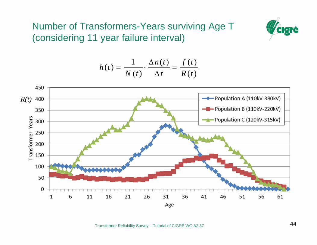
Number of Transformers-Years surviving Age T(considering 11 year failure interval)
44
)()()(
)(1)(
tRtf
ttn
tNth
R(t)
Transformer Reliability Survey – Tutorial of CIGRÉ WG A2.37
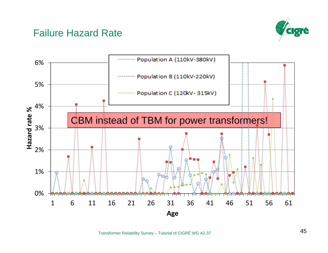
Failure Hazard Rate
45
CBM instead of TBM for power transformers!
0%
1%
2%
3%
4%
5%
6%
1 6 11 16 21 26 31 36 41 46 51 56 61
Hazard rate %
Age

Transformer Reliability Survey – Tutorial of CIGRÉ WG A2.37
Hazard Curve – National Grid (UK)
46
P. Jarman, e. al, „Transformer Life Prediction Using Data fromUnits Removed From Service“ Cigré A2-212, Paris, 2010.

Transformer Reliability Survey – Tutorial of CIGRÉ WG A2.37
Failure Rate Fitting using Weibull Distribution
47
1-t.h(t)
Is Weibull distribution applicable to power transformers?
?
Transformer Reliability Survey – Tutorial of CIGRÉ WG A2.37
RESULTS OF RELIABILITY SURVEY
Failure Location Failure Mode Failure Cause External Effects
48
Transformer Reliability Survey – Tutorial of CIGRÉ WG A2.37
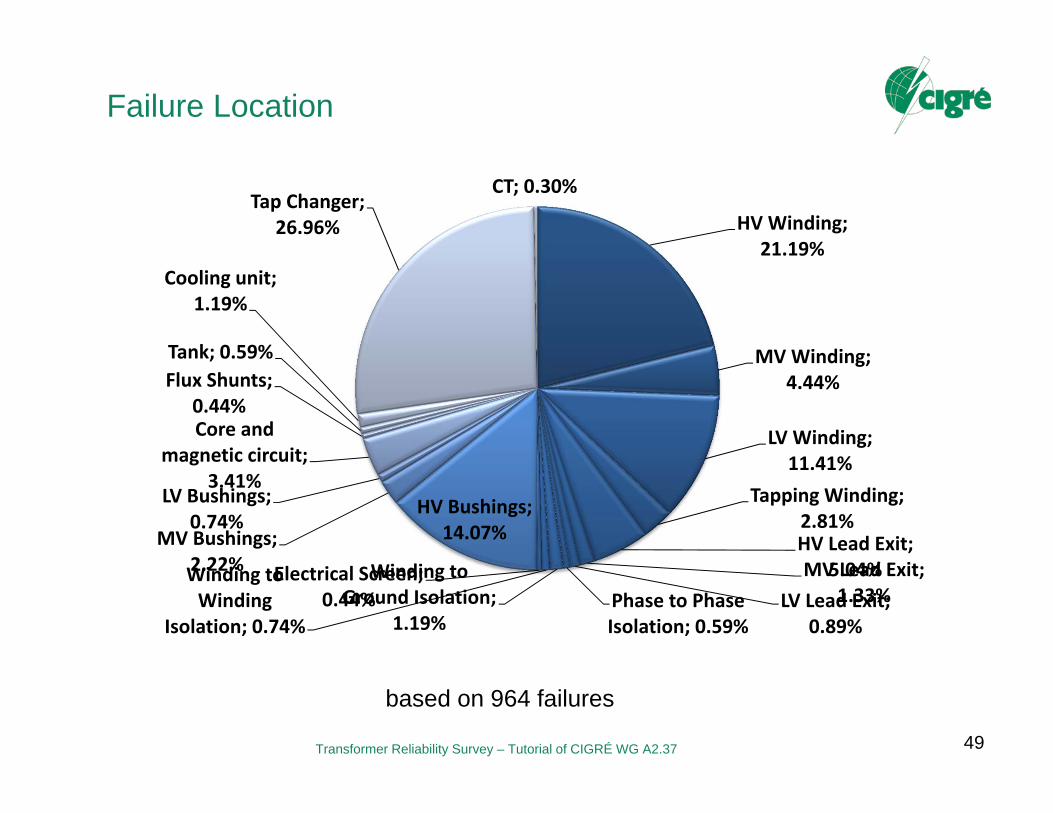
Failure Location
49
based on 964 failures
HV Winding; 21.19%
MV Winding; 4.44%
LV Winding; 11.41%
Tapping Winding; 2.81%HV Lead Exit;
5.04%MV Lead Exit; 1.33%LV Lead Exit;
0.89%Phase to Phase Isolation; 0.59%
Winding to Ground Isolation;
1.19%
Winding to Winding
Isolation; 0.74%
Electrical Screen; 0.44%
HV Bushings; 14.07%MV Bushings;
2.22%
LV Bushings; 0.74%
Core and magnetic circuit;
3.41%
Flux Shunts; 0.44%
Tank; 0.59%
Cooling unit; 1.19%
Tap Changer; 26.96%
CT; 0.30%
Transformer Reliability Survey – Tutorial of CIGRÉ WG A2.37
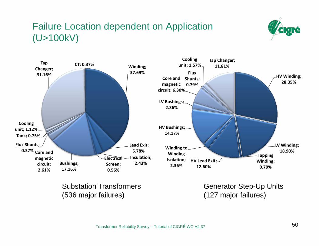
Failure Location dependent on Application(U>100kV)
50
Substation Transformers (536 major failures)
Generator Step-Up Units(127 major failures)
HV Winding; 28.35%
LV Winding; 18.90%
Tapping Winding; 0.79%
HV Lead Exit; 12.60%
Winding to Winding Isolation; 2.36%
HV Bushings; 14.17%
LV Bushings; 2.36%
Core and magnetic
circuit; 6.30%
Flux Shunts; 0.79%
Cooling unit; 1.57%
Tap Changer; 11.81%Winding;
37.69%
Lead Exit; 5.78%Insulation; 2.43%
Electrical Screen; 0.56%
Bushings; 17.16%
Core and magnetic circuit; 2.61%
Flux Shunts; 0.37%
Tank; 0.75%
Cooling unit; 1.12%
Tap Changer; 31.16%
CT; 0.37%
Transformer Reliability Survey – Tutorial of CIGRÉ WG A2.37
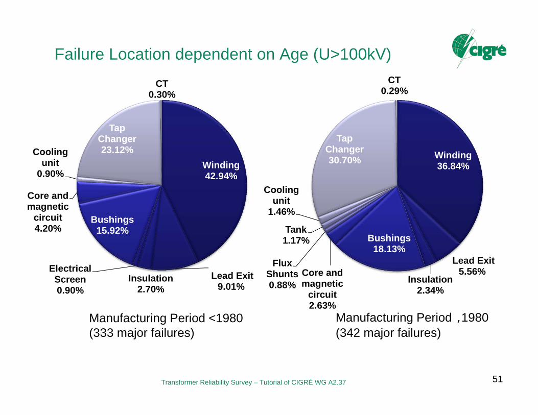
Failure Location dependent on Age (U>100kV)
51
Manufacturing Period <1980(333 major failures)
Manufacturing Period �1980(342 major failures)
Winding42.94%
Lead Exit9.01%
Insulation2.70%
Electrical Screen0.90%
Bushings15.92%
Core and magnetic
circuit4.20%
Cooling unit
0.90%
Tap Changer23.12%
CT0.30%
Winding36.84%
Lead Exit5.56%
Insulation2.34%
Bushings18.13%
Core and magnetic
circuit2.63%
Flux Shunts0.88%
Tank1.17%
Cooling unit
1.46%
Tap Changer30.70%
CT0.29%
Transformer Reliability Survey – Tutorial of CIGRÉ WG A2.37
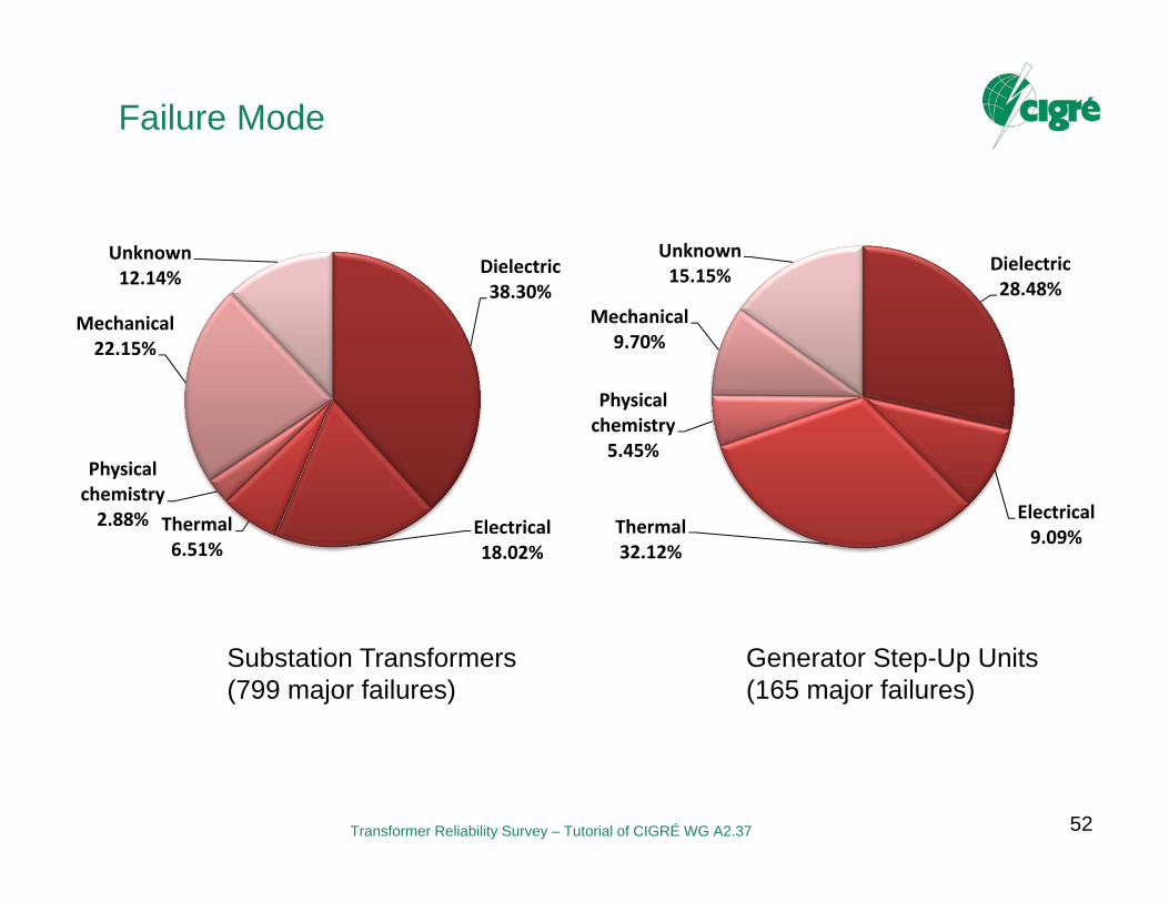
Failure Mode
52
Dielectric38.30%
Electrical18.02%
Thermal6.51%
Physical chemistry 2.88%
Mechanical22.15%
Unknown12.14%
Dielectric28.48%
Electrical9.09%Thermal
32.12%
Physical chemistry5.45%
Mechanical9.70%
Unknown15.15%
Substation Transformers (799 major failures)
Generator Step-Up Units(165 major failures)

Transformer Reliability Survey – Tutorial of CIGRÉ WG A2.37
Failure Cause
53
Unknown29,05%
Aging12.34%
External short-circuit
11.62%
Design9.96%
Manufacturing9.96%
Improper repair6.02%
Other reasons4.88%
Material3.73%Improper
maintenance3.22%
Abnormal Deterioration
2.49%
Lightning2.18%
Installation on-site0.83%Repetitive through
faults0.83%
Overvoltage0.62%
External Pollution0.52%
Loss of clamping pressure0.41%
Overheating0.31%
Collateral Damage0.31%
Improper application
0.21%
Loss of cooling0.21%
Corrosive Sulphur0.21%
Vandalism0.10%
based on 964 failures

Transformer Reliability Survey – Tutorial of CIGRÉ WG A2.37
External Effects
54
based on 964 failures
None; 76.56%
Leakages; 4.25%
Explosion, Burst; 5.91%
Fire; 7.16%
Collateral Damages; 1.24% Others;
4.88%
Failures with Fire or Explosion (126)
Bushing Failures (115)
Transformer Reliability Survey – Tutorial of CIGRÉ WG A2.37
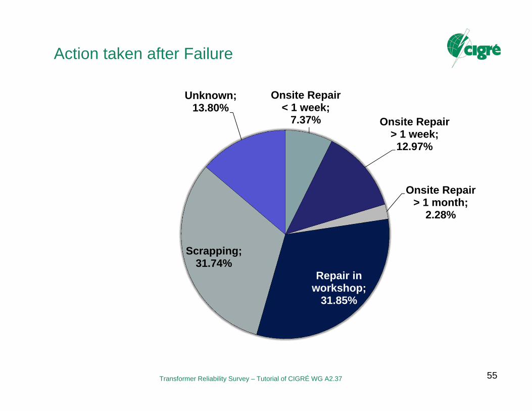
Action taken after Failure
55
Onsite Repair < 1 week;
7.37% Onsite Repair > 1 week; 12.97%
Onsite Repair > 1 month;
2.28%
Repair in workshop;
31.85%
Scrapping; 31.74%
Unknown; 13.80%

Transformer Reliability Survey – Tutorial of CIGRÉ WG A2.37
Action Dependent on Failure Location
56
Scrapped Transformers (242) Repaired Transformers (465)
Winding42.37%
Lead Exit
6.45%Insulation2.15%
Electrical Screen0.65%
Bushings14.62%
Core and magnetic
circuit4.09%
Flux Shunts0.65%
Tank0.86%
Cooling unit
1.51%
Tap Changer26.24%
CT0.43%
Winding64.88%
Lead Exit7.02%
Insulation2.48%
Bushings10.33%
Core and magnetic
circuit2.89%
Tap Changer12.40%

Transformer Reliability Survey – Tutorial of CIGRÉ WG A2.37
Conclusion and Recommendation
57
Review of existing surveys for failure data acquisition: Public available statistics often focused on system reliability and not asset management
A questionnaire was developed by which utility failure statistics can be collected in a standardized way.
Presented results are based on a worldwide population of 23.884 transformers and 167.459 transformer-years with 964 major failures.
Failure rate of 0.53% for substation transformers and 0.95% for GSU. The hazard curve function for substation transformers does not show
a distinct ageing behaviour -> Top-Down analysis is not useful for predictions of individual component. CBM is necessary!
About 50% of major failures occur in the windings. Bushing failures often result in fire or explosions. It is recommended to use questionnaire on a regular basis.