a09 · wolter axv axial flow fans are available for all forms of running. the above ... all belts,...
TRANSCRIPT

Axial Flow Fans- Direct Driven- Belt Driven
A09Wolter Ventilators India Pvt. Ltd. certifies that the series AXV shown herein are licensed to bear the AMCA Seal. The ratings shown are based on tests and procedures performed in accordance with AMCA Publication 211 and AMCA Publication 311 and comply with the requirements of the AMCA Certified Ratings Program. #

1A09 V2013/March
Table of Content
Subject to change without prior notice.
ContentsPage 1
Design FeaturesPage 2
Fan Selection and InstallationPage 3
Selection SamplePage 4
Fan Performance CurvesPage 6~15
Fan Type CodePage 2
Tubular sound attenuator for AXVPage 18
DimensionsPage 16
AMCA FEG RatingPage 5
AccessoriesPage 17

2 A09 V2013/March
Axial Flow FansTechnical information
AXV
Fan type code
AXV-AL 450-26° LH100 -2 SU 400°C/2StdSmoke extract fan 400°C/120min, 300°C/120min
Air flow and form of running S, D, SU, SO, DU, DO
number of poles
Casing versionSH = Short-cased LH1 = Long-cased
Pitch angle
AXV: impeller-Ø355...1000
Axial impeller blade type, material
Design featuresTypes and duty rangeWolter Axial flow fans can be used for various applications in ventilation and process air technology. Standard diameters range from 355 to 1000mm, with airflow rates of up to 82.000 m³/h at static pressure increases of up to 850 Pa. Higher pressures can be achieved by using contra-rotating multi-stage fans.
Belt driven fans are designed for application that required motor to be isolated from the airstreams.
Smoke spill operationThe AXV range of axial fans is designed and tested to operate at standard temperatures as well as at elevated temperatures of 300°C for 60 (F300) and 120 minutes and 400°C for at least 120 minutes (F400), according to DIN EN ISO 12101, part 3. The following fan curves are valid for standard temperatures and 300°/60(120) minutes operation. To select a fan for 400°C/120 minutes operation, please contact our technical support.
CasingFan casings are hot-dip galvanised. Flanges are rolled, the pitch circles of holes are in accordance with DIN 24 154, R2.> LH - Long-cased axial fan, with external terminal box> SH - Short-cased axial fanIf motors require additional lubrication, tubes and grease-nipples are fitted to the outside of the fan casing. An inspection hole, closed by a rubber plug, allows to control the direction of rotation.
ImpellersAXV impellers, hubs and blades are made off pressure-cast aluminium alloy, the aerodynamical profile guarantees high efficiency and low noise levels. The pitch angle is adjustableduring standstill. The variable number of blades the expands the performance range.
MotorWolter uses closed squirrel cage motors according to IEC 34, if required also in accordance with EPACT. Standard motors are class F with IP 55 protection class. Multi speed versions with 2 or 3 speeds (Dahlander circuit or separate windings) are also available, as well as explosion-proof
versions or specific industrial executions such as marine-type fans. The motor bearings have a L 10 life.
Forms of runningWolter AXV axial flow fans are available for all forms of running. The above chart shows all standard forms of running. Please indicate the required configuration when ordering. Without specific instructions, fans will be delivered in configuration S. Arrows outside the fan casing indicates the correct direction of rotation and airflow.
Fan performance curvesThe performance curves for these fan types have been established in mounting position D (according to AMCA 210, installed on the pressure side and suction side) and represent the total pressure increase Dpt as a function of the volume flow. The dynamic pressure pd2 refers to the flange cross-sectional area at the of the fan.
Sound levelsThe ascertaining of sound level follows the Recerberant Room Method according to AMCA 300. The A-weighted sound power levels is shown on the performace curves.
Safety FeaturesAll fans are labelled with name plate securely attached on each fan showing the serial and model number, fan and drive duties, rotation of flow and date of manufacture. All belts, pulleys, projecting set screws, keys and other rotating external parts are properly guarded conforming to safety standards in accordance with Factory Act requirements.
Ordering designationsWhen ordering, please provide the following information:> fan type code (see above), casing version and form of running> duty required at standard air temperature (air volume in m³/h at static pressure in Pa)> motor power rating in kW> electrical supply> required ancillary equipment
AMCA 210 Figure 12ISO 5801 Figure 73b
Test Setups
ISO 5801 Figure 73bAMCA 210 Figure 12
Outlet chamber
Auxilliary Fan
Nozzles
Test Fan
Settlingmeans
Test Setups
ISO 5801 Figure 73bAMCA 210 Figure 12
Outlet chamber
Auxilliary Fan
Nozzles
Test Fan
Settlingmeans
Test Setups
ISO 5801 Figure 73bAMCA 210 Figure 12
Outlet chamber
Auxilliary Fan
Nozzles
Test Fan
Settlingmeans
Test Fan

3A09 V2013/March
!"AXV DD AXV BD
Fan selection and installationFan selectionPlease select fans according to the nearest performance curve above the required duty point. The middle range of each fan curve is the area of highest efficiency. Do not select fans at the upper end of the fan curve, as this might cause the fan to work in stall. In order to avoid motor overloading, please select motors according to the peak power of the respective performance curve. Please refer to the selection example on the following page.
Fan installationWhen installing the fan, please consider the following instructions:> Fans with free inlet and outlet should be installed with an unobstructed distance of at least 1,5 x fan diameter on suction and pressure sides. Fans should have a bellmouth on the inlet side in order to assure optimal incoming flow. A diffusor mounted on the pressure side will increase efficiency.
> When installing fans in a ducted system, adequate distance to other structural parts such as bends, filters and silencers should be provided for. A sharp bond radius of the duct near the suction or pressure side of the fan is to be avoided. Flexible connections are to be installed in a way that does not obstruct the outlet cross section of the fan (see following page).
Casing SH
Casing LH
S SU SO
D DU DO
Bad Right1
Wrong Right
duct length min. 1xØ
2
Wrong Right3
1,5 x D
Wrong Right4

4 A09 V2013/March
Axial Flow FansTechnical information
AXV
Selection exampleRequired duty point
>Volume flow : 5.000 m3/h >Static pressure: 110 Pa
>
In order to calculate the total pressure, please add velocity pressure to static pressure (30 Pa dynamic pressure + 110 Pa static pressure = 140 Pa total pressure) >Fan speed: 1.440 1/min (4-pole)
Using the fan curveHaving chosen a fan with adequate performance range for the required duty point, plot volume flow and pressure.At the point of intersection, the following data can be read:
>Motor speed or number of poles 1.440 1/min - 4-pole >Pitch angle: 18 degrees >FEG Rating: FEG71 (see page5) >Inlet sound power level: 80 dB(A)
Calculation of motor power:There are two possibilities to calculate the motor power:1) Calculation of absorbed power by using the fan curve in duty point:
0,338 kWMotor power: 0,37 kW
2) Calculation according to peak absorbed power, see table below the fan curve: 0,366 kW
Motor power: 0,37 kW
The given peak absorbed power is the maximum shaft absorbed power over the whole pitch angle curve in.
0.2 0.4 0.6 0.8 1 1.2 1.4 1.6 1.81000 2000 3000 4000 5000 6000 700
0.5 0.75 1 1.25 1.5 1.75 2 2.25 2.5 2.751000 2000 3000 4000 5000 6000 7000 8000 9000 10000
1 1.5 2 2.5 3 3.5 4 4.5 5 5.52500 5000 7500 10000 12500 15000 17500 20000
0
20
40
60
80
100
0
50
100
150
200
250
0
200
400
600
800
1000
0.05
0.1
0.15
0.2
0.2
0.4
0.6
0.8
2
4
6
10°12°
14°16°
20°22°
24°
26°
28°
30°
10° 12° 14° 16°
20°22°
24°26°
28°30°
8°
18 °
32 °
8°
18°
32 °
2880 1/min
1440 1/min
960 1/min
Pd
645004, AXV-AL 500, 2880, 1440, 960

5A09 V2013/March
!"AXV DD AXV BD
Certified FEGs are determined in accordance with AMCA 205-12 Energy Efficiency Classification for fans.In conjunction with AMCA 211-05 (Rev. 6/12) Certified Ratings Program, Product Rating Manual for Fan Air Performance. This classification is based on fan peak (optimum) total efficiency for a given fan speed, fan size and application category. For the purpose of energy classification, the peak efficiency can be determined at a speed not higher than the maximum design speed of the fan.
The AMCA Certified Ratings Seal applies to the Fan Efficiency Grade (FEG) for AXV series Axial Fan model AXV 355 to AXV 1000 as shown in the table below.
Fan Model
No.
Fan Speed(rpm)
Fan Outlet
Area (m2)
Fan Efficiency
Grades (FEG)
Fan Model
No.
Fan Speed(rpm)
Fan Outlet
Area (m2)
Fan Efficiency
Grade(FEG)
AXV 355-7 2880/1440/960 0,1012 FEG63 AXV 630-9 2880/1440/960 0,3167 FEG63
AXV 400-7 2880/1440/960 0,1269 FEG67 AXV 710-9 1440/960/720 0,3982 FEG67
AXV 450-7 2880/1440/960 0,1590 FEG63 AXV 800-9 1440/960/720 0,5001 FEG67
AXV 500-7 2880/1440/960 0,2003 FEG71 AXV 900-10 1440/960/720 0,6333 FEG63
AXV 560-9 2880/1440/960 0,2516 FEG67 AXV 1000-10 1440/960/720 0,7980 FEG71
Notes:1. Fan size is the impeller diameter in mm.2. The fan peak efficiency shall be calculated from the fan (total) pressure.3. If this method is used for a direct driven fan, the fan efficiency is the impeller efficiency.4. The FEG label for a given fan size is assigned when the fan peak efficiency is equal or lower than the efficiency at the
grade upper limit and higher than efficiency at the grade upper limit of the next lower grade for the fan size. 5. For any fan sizes larger than 1016 mm, the values of the grade upper limits are the same as for a size of 1016 mm.6. No labels are considered for the fans with the fan peak total efficiency below FEG50.7. The values of efficiencies are calculated for fan sizes in the preferred R40 Series.8. Not all fan sizes in preferred numbers shown.
Figure 3aFan Efficiency Grades (FEG) for Fans without Drives (SI)
6 | AMCA 205-10
Fan size (mm)
Fan
Peak
Tot
al E
ffici
ency
(%)
0 100 200 300 400 500 600 700 800 900 1000 110020
30
40
50
60
70
80
90
125160 200 250 315 355 400 450 500 560 630 710 800 900 1000
Fan sizes in preferred numbers
FEG50FEG53FEG56
FEG60
FEG63
FEG67
FEG71
FEG75
FEG80
FEG85
FEG90
AMCA - FEG ratingFan Efficiency Grade - AXV

6 A09 V2013/March
!"PerformanceCurve
0.1 0.2 0.3 0.4 0.5 0.6 0.7500 750 1000 1250 1500 1750 2000 2250 2500 2750
0.2 0.3 0.4 0.5 0.6 0.7 0.8 0.9 1 1.1500 1000 1500 2000 2500 3000 3500 4000
0.5 0.75 1 1.25 1.5 1.75 2 2.251000 2000 3000 4000 5000 6000 7000 8000
0
10
20
30
40
50
0
25
50
75
100
125
0
100
200
300
400
500
0.02
0.04
0.05
0.1
0.15
0.2
0.5
1
1.5
12°14°
16°18°
20°22°
24°
28°30°
32°
34°
36°
38°
12° 14° 16° 18° 20° 22° 24°
28°30°
32°34°
36°38°
10°
26°
40°
10 °
26°
40°
2880 1/min
1440 1/min
960 1/min
Pd
AbsorbedPower(kw)
TotalPressure(Pa)
645024, AXV-AL 355, 2880, 1440, 960
AXV 355-7, 50 Hz
- 0,018 0,020 0,022 0,024 0,026 0,028 0,031 0,033 0,035 0,038 0,041 0,044 0,047 0,050 0,053 0,056
0,37
- 0,061 0,068 0,075 0,082 0,089 0,096 0,103 0,110 0,117 0,127 0,137 0,148 0,158 0,169 0,180 0,190
0,37
- 0,488 0,544 0,600 0,656 0,712 0,768 0,824 0,880 0,936 1,01 1,10 1,18 1,267 1,352 1,44 1,52
0,55 0,75 1,1 1,5 2,2
960motor 1440motor2880motor
Peak absorbed power [kW]
Volume flow V. [m³/h]
[m³/s]
Tota
l pre
ssur
e D
p t [PA]
Abs
orbe
d po
wer
[kW
]
Speed [min-1]
1440 4-pol
960 6-pol
2880 2-pol
n[min-1]
Pitch angle [°]8 10 12 14 16 18 20 22 24 26 28 30 32 34 36 38 40
Fan test laboratory AMCA 210/99 Fig.12, Test Chamber. Performance certified is for installation type D - Ducted inlet, Ducted outlet. Performance ratings do not include the effects of appurtenances (accessories-belt cover, pulley & belt).
The A-weighted sound ratings shown have been calculated per AMCA International Standard 301. Values shown are for inlet LwiA sound power levels for installation Type D: ducted inlet, ducted outlet. Ratings include the effects of duct end correction.
ρ = 1,2 kg/m3
Lwi(A) a b c d e f g h j k m n2P4P6P
a
b
c
d
e
f
g
h
j
k
m
96 93 93 98 103 103 104 100 104 105 106 -75 74 74 77 81 82 83 79 83 84 84 -62 62 62 65 68 69 70 67 70 71 71 -

7A09 V2013/March
!"PerformanceCurve
0.2 0.3 0.4 0.5 0.6 0.7 0.8 0.9 11000 1500 2000 2500 3000 3500
0.4 0.6 0.8 1 1.2 1.4 1.61000 2000 3000 4000 5000
0.5 1 1.5 2 2.5 32000 4000 6000 8000 10000
0
10
20
30
40
50
60
0
25
50
75
100
125
0
100
200
300
400
500
0.02
0.04
0.06
0.08
0.05
0.1
0.15
0.2
0.25
0.3
0.5
1
1.5
2
2.5
12°14°
16°18°
20°22°
24°
28°
30°
32°
34°
36°
38°
12° 14° 16° 18° 20° 22° 24°
28°
30°
32°
34°
36°
38°
10°
26°
40°
10°
26°
40 °
2880 1/min
1440 1/min
960 1/min
Pd
AbsorbedPower(kw)
TotalPressure(Pa)
645023, AXV-AL 400, 2880, 1440, 960
AXV 400-7, 50 Hz
960motor 1440motor2880motor
- 0,021 0,024 0,027 0,030 0,032 0,035 0,038 0,041 0,044 0,050 0,056 0,061 0,067 0,073 0,079 0,085
0,37
- 0,072 0,081 0,091 0,100 0,109 0,119 0,128 0,138 0,148 0,168 0,188 0,207 0,227 0,248 0,268 0,288
0,37
- 0,576 0,650 0,724 0,798 0,872 0,948 1,03 1,11 1,18 1,34 1,50 1,66 1,82 1,98 2,14 2,31
0,75 1,1 1,5 2,2 3
Volume flow V. [m³/h]
[m³/s] Peak absorbed power [kW]
Tota
l pre
ssur
e D
p t [PA]
Abs
orbe
d po
wer
[kW
]
Speed [min-1]
1440 4-pol
960 6-pol
2880 2-pol
Pitch angle [°]8 10 12 14 16 18 20 22 24 26 28 30 32 34 36 38 40
n[min-1]
Fan test laboratory AMCA 210/99 Fig.12, Test Chamber. Performance certified is for installation type D - Ducted inlet, Ducted outlet. Performance ratings do not include the effects of appurtenances (accessories-belt cover, pulley & belt).
The A-weighted sound ratings shown have been calculated per AMCA International Standard 301. Values shown are for inlet LwiA sound power levels for installation Type D: ducted inlet, ducted outlet. Ratings include the effects of duct end correction.
ρ = 1,2 kg/m3
Lwi(A) a b c d e f g h j k m n2P4P6P
a
b
c
d
e
f
g
h
j
k
m
100 97 93 98 95 96 97 99 98 98 100 -79 79 75 79 77 77 77 79 79 79 81 -66 68 64 68 66 66 66 68 68 68 69 -

8 A09 V2013/March
!"PerformanceCurve
0.2 0.4 0.6 0.8 1 1.2500 1000 1500 2000 2500 3000 3500 4000 4500
0.2 0.4 0.6 0.8 1 1.2 1.4 1.6 1.8 21000 2000 3000 4000 5000 6000 7000
0.5 1 1.5 2 2.5 3 3.5 42500 5000 7500 10000 12500
0
10
20
30
40
50
60
70
80
0
25
50
75
100
125
150
175
0
100
200
300
400
500
600
700
0.02
0.04
0.06
0.08
0.05
0.1
0.15
0.2
0.25
0.3
1
2
3
10°12°
14°16°
20°22°
24°
26°
28°
30°
10° 12° 14° 16°
20°22°
24°26°
28°30°
8°
18°
32°
8°
18°
32°
2880 1/min
1440 1/min
960 1/min
Pd
AbsorbedPower(kw)
TotalPressure(Pa)
645003, AXV-AL 450, 2880, 1440, 960
AXV 450-7, 50 Hz
0,043 0,049 0,054 0,059 0,065 0,070 0,079 0,088 0,097 0,106 0,114 0,123 0,132 - - - -
0,37
0,146 0,164 0,182 0,200 0,218 0,237 0,267 0,297 0,327 0,356 0,386 0,416 0,446 - - - -
0,37 0,55
1,17 1,31 1,45 1,60 1,75 1,90 2,14 2,38 2,61 2,852 3,09 3,33 3,567 - - - -
1,5 2,2 3 4
960motor 1440motor2880motor
Peak absorbed power [kW]
Volume flow V. [m³/h]
[m³/s]
Tota
l pre
ssur
e D
p t [PA]
Abs
orbe
d po
wer
[kW
]
Speed [min-1]
1440 4-pol
960 6-pol
2880 2-pol
n[min-1]
Pitch angle [°]8 10 12 14 16 18 20 22 24 26 28 30 32 34 36 38 40
Fan test laboratory AMCA 210/99 Fig.12, Test Chamber. Performance certified is for installation type D - Ducted inlet, Ducted outlet. Performance ratings do not include the effects of appurtenances (accessories-belt cover, pulley & belt).
The A-weighted sound ratings shown have been calculated per AMCA International Standard 301. Values shown are for inlet LwiA sound power levels for installation Type D: ducted inlet, ducted outlet. Ratings include the effects of duct end correction.
ρ = 1,2 kg/m3
Lwi(A) a b c d e f g h j k m n2P4P6P
a
b
c
d
e
f
g
h
j
k
m
n
102 103 98 99 100 97 99 98 98 100 101 10181 82 80 80 82 78 79 79 79 80 81 8268 69 69 69 71 67 68 69 68 68 69 70

9A09 V2013/March
!"PerformanceCurve
0.2 0.4 0.6 0.8 1 1.2 1.4 1.6 1.81000 2000 3000 4000 5000 6000 7000
0.5 0.75 1 1.25 1.5 1.75 2 2.25 2.5 2.751000 2000 3000 4000 5000 6000 7000 8000 9000 10000
1 1.5 2 2.5 3 3.5 4 4.5 5 5.52500 5000 7500 10000 12500 15000 17500 20000
0
20
40
60
80
100
0
50
100
150
200
250
0
200
400
600
800
1000
0.05
0.1
0.15
0.2
0.2
0.4
0.6
0.8
2
4
6
10°12°
14°16°
20°22°
24°
26°
28°
30°
10° 12° 14° 16°
20°22°
24°26°
28°30°
8°
18 °
32 °
8°
18°
32 °
2880 1/min
1440 1/min
960 1/min
Pd
AbsorbedPower(kw)
TotalPressure(Pa)
645004, AXV-AL 500, 2880, 1440, 960
AXV 500-7, 50 Hz
960motor 1440motor2880motor
0,058 0,068 0,078 0,088 0,098 0,108 0,124 0,141 0,155 0,171 0,187 0,202 0,218 - - - -
0,37
0,194 0,228 0,262 0,297 0,331 0,366 0,419 0,471 0,524 0,577 0,630 0,683 0,736 - - - -
0,37 0,55 0,75
1,55 1,83 2,10 2,37 2,65 2,93 3,35 3,77 4,19 4,61 5,04 5,46 5,89 - - - -
2,2 3 4 5,5 7,5
Volume flow V. [m³/h]
[m³/s] Peak absorbed power [kW]
Tota
l pre
ssur
e D
p t [PA]
Abs
orbe
d po
wer
[kW
]
Speed [min-1]
1440 4-pol
960 6-pol
2880 2-pol
Pitch angle [°]8 10 12 14 16 18 20 22 24 26 28 30 32 34 36 38 40
n[min-1]
Fan test laboratory AMCA 210/99 Fig.12, Test Chamber. Performance certified is for installation type D - Ducted inlet, Ducted outlet. Performance ratings do not include the effects of appurtenances (accessories-belt cover, pulley & belt).
The A-weighted sound ratings shown have been calculated per AMCA International Standard 301. Values shown are for inlet LwiA sound power levels for installation Type D: ducted inlet, ducted outlet. Ratings include the effects of duct end correction.
ρ = 1,2 kg/m3
Lwi(A) a b c d e f g h j k m n2P4P6P
a
b
c
d
e
f
g
h
j
k
m
n
100 100 98 99 100 99 99 100 100 101 101 10380 82 80 81 81 80 80 81 82 82 82 8369 71 69 70 71 69 69 70 71 71 71 72

10 A09 V2013/March
!"PerformanceCurve AXV 560-9, 50 Hz
0.5 0.75 1 1.25 1.5 1.75 2 2.25 2.51000 2000 3000 4000 5000 6000 7000 8000 9000
0.5 1 1.5 2 2.5 3 3.5 42000 4000 6000 8000 10000 12000 14000
1 2 3 4 5 6 7 85000 10000 15000 20000 25000
0
25
50
75
100
0
50
100
150
200
250
0
200
400
600
800
1000
0.1
0.2
0.3
0.4
0.25
0.5
0.75
1
1.25
2.5
5
7.5
10
10°12°
14°16°
18°
22°
24°
26°
28°
30°
10° 12° 14° 16° 18°
22°
24°
26°
28°
30°
8°
20°
32°
8°
20°
32°
2880 1/min
1440 1/min
960 1/min
Pd
AbsorbedPower(kw)
TotalPressure(Pa)
645021, AXV-AL 560, 2880, 1440, 960
0,104 0,119 0,133 0,148 0,163 0,178 0,194 0,228 0,261 0,295 0,329 0,362 0,396 - - - -
0,37 0,55
0,351 0,401 0,450 0,500 0,551 0,602 0,655 0,769 0,882 0,995 1,11 1,22 1,34 - - - -
0,37 0,55 0,75 1,1 1,5
2,81 3,21 3,60 4,01 4,41 4,82 5,24 6,15 7,06 7,96 8,87 9,78 10,7 - - - -
3 4 5,5 7,5 11
960motor 1440motor2880motor
Peak absorbed power [kW]
Volume flow V. [m³/h]
[m³/s]
Tota
l pre
ssur
e D
p t [PA]
Abs
orbe
d po
wer
[kW
]
Speed [min-1]
1440 4-pol
960 6-pol
2880 2-pol
n[min-1]
Pitch angle [°]8 10 12 14 16 18 20 22 24 26 28 30 32 34 36 38 40
Fan test laboratory AMCA 210/99 Fig.12, Test Chamber. Performance certified is for installation type D - Ducted inlet, Ducted outlet. Performance ratings do not include the effects of appurtenances (accessories-belt cover, pulley & belt).
The A-weighted sound ratings shown have been calculated per AMCA International Standard 301. Values shown are for inlet LwiA sound power levels for installation Type D: ducted inlet, ducted outlet. Ratings include the effects of duct end correction.
ρ = 1,2 kg/m3
Lwi(A) a b c d e f g h j k m n2P4P6P
a
b
c
d
e
f
g
h
j
k
m
n
107 105 106 104 109 107 106 108 110 111 112 11287 87 89 85 90 88 87 88 91 91 91 9279 79 79 80 79 76 76 77 75 76 78 73
11A09 V2013/March
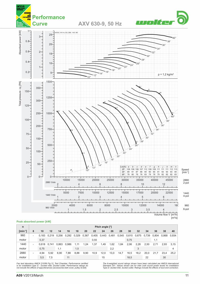
!"PerformanceCurve AXV 630-9, 50 Hz
1 1.5 2 2.5 3 3.5 42000 4000 6000 8000 10000 12000 14000 16000
1 2 3 4 5 65000 7500 10000 12500 15000 17500 20000 22500
2 4 6 8 10 1210000 15000 20000 25000 30000 35000 40000 45000
0
25
50
75
100
125
150
0
50
100
150
200
250
300
350
0
250
500
750
1000
1250
1500
0.2
0.4
0.6
0.8
1
1
2
3
5
10
15
20
25
12°14°
16°18°
20°22°
24°
28°
30°
32°
34°
36°
38°
12°14°
16°18°
20°22°
24°
28°30°
32°34°
36°38°
10°
26 °
40°
10 °
26°
40 °
2880 1/min
1440 1/min
960 1/min
Pd
AbsorbedPower(kw)
TotalPressure(Pa)
645002, AXV-AL 630, 2880, 1440, 960
960motor 1440motor2880motor
- 0,183 0,219 0,256 0,292 0,329 0,367 0,405 0,443 0,481 0,545 0,610 0,675 0,739 0,804 0,868 0,934
0,37 0,55 0,75 1,1
- 0,618 0,741 0,863 0,986 1,11 1,24 1,37 1,49 1,62 1,84 2,06 2,28 2,50 2,71 2,93 3,15
0,75 1,1 1,5 2,2 3 4
- 4,94 5,92 6,90 7,88 8,88 9,90 10,9 12,0 13,0 14,7 16,5 18,2 20,0 21,7 23,4 25,2
5,5 7,5 11 15 18,5 22 30
Volume flow V. [m³/h]
[m³/s] Peak absorbed power [kW]
Tota
l pre
ssur
e D
p t [PA]
Abs
orbe
d po
wer
[kW
]
Speed [min-1]
1440 4-pol
960 6-pol
2880 2-pol
Pitch angle [°]8 10 12 14 16 18 20 22 24 26 28 30 32 34 36 38 40
n[min-1]
Fan test laboratory AMCA 210/99 Fig.12, Test Chamber. Performance certified is for installation type D - Ducted inlet, Ducted outlet. Performance ratings do not include the effects of appurtenances (accessories-belt cover, pulley & belt).
The A-weighted sound ratings shown have been calculated per AMCA International Standard 301. Values shown are for inlet LwiA sound power levels for installation Type D: ducted inlet, ducted outlet. Ratings include the effects of duct end correction.
ρ = 1,2 kg/m3
Lwi(A) a b c d e f g h j k m n2P4P6P
a
b
c
d
e
f
g
h
jk
m
n
109 108 106 107 112 108 109 111 111 111 112 11389 91 87 88 94 90 90 91 93 93 93 9478 80 76 76 83 79 78 79 82 82 82 83

12 A09 V2013/March
!"PerformanceCurve AXV 710-9, 50 Hz
1 1.5 2 2.5 3 3.5 4 4.52000 4000 6000 8000 10000 12000 14000 16000
1 1.5 2 2.5 3 3.5 4 4.5 5 5.5 65000 7500 10000 12500 15000 17500 20000
2 3 4 5 6 7 8 95000 10000 15000 20000 25000 30000
0
25
50
75
100
125
0
50
100
150
200
0
100
200
300
400
500
0.2
0.4
0.6
0.5
1
1.5
1
2
3
4
5
10°12°
14°16°
18°20°
24°26°
28°
30°
32°
34°
10° 12° 14° 16° 18° 20°
24°26°
28°30°
32°
34°
8°
22°
36°
8°
22°
36°
1440 1/min
960 1/min
720 1/min
Pd
AbsorbedPower(kw)
TotalPressure(Pa)
645006, AXV-AL 710 , 1440, 960, 720
720motor 960
motor1440motor
0,125 0,149 0,175 0,201 0,228 0,255 0,282 0,309 0,353 0,397 0,440 0,484 0,528 0,572 0,616 - -
0,37 0,55 0,75
0,295 0,353 0,414 0,477 0,541 0,604 0,668 0,732 0,836 0,940 1,04 1,15 1,25 1,36 1,46 - -
0,37 0,55 0,75 1,1 1,5
0,996 1,19 1,40 1,61 1,83 2,04 2,26 2,47 2,82 3,17 3,52 3,87 4,22 4,58 4,93 - -
1,1 1,5 2,2 3 4 5,5
Peak absorbed power [kW]
Volume flow V. [m³/h]
[m³/s]
Tota
l pre
ssur
e D
p t [PA]
Abs
orbe
d po
wer
[kW
]
Speed [min-1]
1440 4-pol
960 6-pol
2880 2-pol
n[min-1]
Pitch angle [°]8 10 12 14 16 18 20 22 24 26 28 30 32 34 36 38 40
Fan test laboratory AMCA 210/99 Fig.12, Test Chamber. Performance certified is for installation type D - Ducted inlet, Ducted outlet. Performance ratings do not include the effects of appurtenances (accessories-belt cover, pulley & belt).
The A-weighted sound ratings shown have been calculated per AMCA International Standard 301. Values shown are for inlet LwiA sound power levels for installation Type D: ducted inlet, ducted outlet. Ratings include the effects of duct end correction.
ρ = 1,2 kg/m3
Lwi(A) a b c d e f g h j k m n2P4P6P
a
b
c
d
e
f
g
h
k
m
j
960 6-pol
720 8-pol
1440 4-pol
4P6P8P
94 93 90 93 92 92 94 96 96 97 98 -84 83 79 83 81 81 83 85 85 86 87 -76 76 71 75 73 73 75 77 77 77 78 -

13A09 V2013/March
!"PerformanceCurve AXV 800-9, 50 Hz
1 2 3 4 5 62500 5000 7500 10000 12500 15000 17500 20000 22500
1 2 3 4 5 6 7 85000 10000 15000 20000 25000 30000
2 4 6 8 10 125000 10000 15000 20000 25000 30000 35000 40000 45000
0
25
50
75
100
125
0
50
100
150
200
0
100
200
300
400
500
0.25
0.5
0.75
1
0.5
1
1.5
2
2.5
2.5
5
7.5
10°12°
14°16°
18°20°
24°
26°
28°
30°
32°
34°
10°12°
14°16°
18°20°
24°26°
28°30°
32°34°
8°
22°
36°
8°
22°
36 °
1440 1/min
960 1/min
720 1/min
Pd
AbsorbedPower(kw)
TotalPressure(Pa)
645012, AXV-AL 800, 1440, 960, 720
720motor 960
motor1440motor
0,186 0,225 0,265 0,306 0,348 0,390 0,432 0,474 0,549 0,624 0,699 0,774 0,849 0,924 0,999 - -
0,37 0,55 0,75 1,1
0,440 0,533 0,628 0,726 0,825 0,925 1,02 1,12 1,30 1,48 1,66 1,83 2,01 2,19 2,37 - -
0,55 0,75 1,1 1,5 2,2 3
1,49 1,80 2,12 2,45 2,79 3,12 3,46 3,79 4,39 4,99 5,59 6,19 6,79 7,39 7,99 - -
1,5 2,2 3 4 5,5 7,5 11
Volume flow V. [m³/h]
[m³/s] Peak absorbed power [kW]
Tota
l pre
ssur
e D
p t [PA]
Abs
orbe
d po
wer
[kW
]
Speed [min-1]
1440 4-pol
960 6-pol
2880 2-pol
Pitch angle [°]8 10 12 14 16 18 20 22 24 26 28 30 32 34 36 38 40
n[min-1]
Fan test laboratory AMCA 210/99 Fig.12, Test Chamber. Performance certified is for installation type D - Ducted inlet, Ducted outlet. Performance ratings do not include the effects of appurtenances (accessories-belt cover, pulley & belt).
The A-weighted sound ratings shown have been calculated per AMCA International Standard 301. Values shown are for inlet LwiA sound power levels for installation Type D: ducted inlet, ducted outlet. Ratings include the effects of duct end correction.
ρ = 1,2 kg/m3
Lwi(A) a b c d e f g h j k m n2P4P6P
a
b
c
d
e
f
g
h
j
k
m
n
960 6-pol
720 8-pol
1440 4-pol
4P6P8P
95 95 99 92 101 95 95 95 99 99 99 10184 84 88 82 91 84 84 84 89 88 88 8976 76 81 74 83 76 76 77 81 81 81 81

14 A09 V2013/March
!"PerformanceCurve AXV 900-10, 50 Hz
2 3 4 5 6 7 85000 10000 15000 20000 25000 30000
2 4 6 8 1010000 15000 20000 25000 30000 35000 40000
2.5 5 7.5 10 12.5 1510000 20000 30000 40000 50000 60000
0
25
50
75
100
125
150
175
0
50
100
150
200
250
300
0
100
200
300
400
500
600
700
0.5
1
1.5
1
2
3
4
5
10
15
10°12°
14°16°
20°
22°
24°
26°
28°
30°
10° 12° 14° 16°
20°22°
24°26°
28°30°
8°
18 °
32°
8°
18°
32°
1440 1/min
960 1/min
720 1/min
Pd
645011, AXV-AL 900, 1440, 960, 720
720motor 960
motor1440motor
0,376 0,456 0,536 0,617 0,699 0,780 0,914 1,05 1,18 1,32 1,45 1,59 1,72 - - - -
0,55 0,75 1,1 1,5 2,2
0,891 1,08 1,27 1,46 1,66 1,85 2,17 2,49 2,80 3,12 3,44 3,76 4,08 - - - -
1,1 1,5 2,2 3 4 5,5
3,01 3,64 4,30 4,93 5,59 6,24 7,31 8,39 9,46 10,5 11,6 12,7 13,8 - - - -
4 5,5 7,5 11 15
Peak absorbed power [kW]
Volume flow V. [m³/h]
[m³/s]
Tota
l pre
ssur
e D
p t [PA]
Abs
orbe
d po
wer
[kW
]
Speed [min-1]
1440 4-pol
960 6-pol
2880 2-pol
n[min-1]
Pitch angle [°]8 10 12 14 16 18 20 22 24 26 28 30 32 34 36 38 40
Fan test laboratory AMCA 210/99 Fig.12, Test Chamber. Performance certified is for installation type D - Ducted inlet, Ducted outlet. Performance ratings do not include the effects of appurtenances (accessories-belt cover, pulley & belt).
The A-weighted sound ratings shown have been calculated per AMCA International Standard 301. Values shown are for inlet LwiA sound power levels for installation Type D: ducted inlet, ducted outlet. Ratings include the effects of duct end correction.
ρ = 1,2 kg/m3
Lwi(A) a b c d e f g h j k m n2P4P6P
a
b
c
d
e
f
g
h
k
m
j
960 6-pol
720 8-pol
1440 4-pol
4P6P8P
99 101 97 100 97 97 98 100 100 100 101 -88 91 87 90 87 86 87 90 89 90 91 -80 83 80 83 80 79 79 82 82 82 83 -

15A09 V2013/March
!"PerformanceCurve AXV 1000-10, 50 Hz
2 3 4 5 6 7 8 9 10 115000 10000 15000 20000 25000 30000 35000 40000
2 4 6 8 10 12 1410000 15000 20000 25000 30000 35000 40000 45000 50000 55000
2.5 5 7.5 10 12.5 15 17.5 20 22.510000 20000 30000 40000 50000 60000 70000 80000
0
25
50
75
100
125
150
175
200
225
0
50
100
150
200
250
300
350
400
0
100
200
300
400
500
600
700
800
900
1
2
3
2
4
6
5
10
15
20
10°12°
14°16°
20°
22°
24°
26°
28°
30°
10°12°
14° 16°
20°22°
24°26°
28°30°
8°
18°
32°
8°
18°
32°
1440 1/min
960 1/min
720 1/min
Pd
645000, AXV-AL 1000, 1440, 960, 720
720motor 960
motor1440motor
0,654 0,798 0,942 1,09 1,23 1,38 1,59 1,80 2,01 2,22 2,44 2,65 2,86 - - - -
0,75 1,1 1,5 2,2 3
1,55 1,89 2,23 2,58 2,92 3,26 3,76 4,26 4,77 5,27 5,77 6,27 6,78 - - - -
2,2 3 4 5,5 7,5
5,23 6,38 7,54 8,69 9,85 11,0 12,7 14,4 16,1 17,8 19,5 21,2 22,9 - - - -
5,5 7,5 11 15 18,5 22 30
Volume flow V. [m³/h]
[m³/s] Peak absorbed power [kW]
Tota
l pre
ssur
e D
p t [PA]
Abs
orbe
d po
wer
[kW
]
Speed [min-1]
1440 4-pol
960 6-pol
2880 2-pol
Pitch angle [°]8 10 12 14 16 18 20 22 24 26 28 30 32 34 36 38 40
n[min-1]
Fan test laboratory AMCA 210/99 Fig.12, Test Chamber. Performance certified is for installation type D - Ducted inlet, Ducted outlet. Performance ratings do not include the effects of appurtenances (accessories-belt cover, pulley & belt).
The A-weighted sound ratings shown have been calculated per AMCA International Standard 301. Values shown are for inlet LwiA sound power levels for installation Type D: ducted inlet, ducted outlet. Ratings include the effects of duct end correction.
ρ = 1,2 kg/m3
Lwi(A) a b c d e f g h j k m n2P4P6P
a
b
c
d
e
f
g
h
j
k
m
n
960 6-pol
720 8-pol
1440 4-pol
4P6P8P
102 105 99 100 103 101 100 102 104 103 104 10591 95 89 89 93 91 90 91 94 93 94 9483 88 81 82 86 83 83 84 87 86 87 87

16 A09 V2013/March
AXVAxial Flow FansDimensions
LH SH
LH/1 LH/2 SHModel s k1 l1 motor s k1 l1 motor s k2 l2 lmaxsize [mm] [mm] [mm] max. [mm] [mm] [mm] max. [mm] [mm] [mm] [mm]
355 2 356 420 80 2 161 225 350400 2 371 435 90 2 161 225 400450 2 371 435 112 2 161 225 500500 2 396 470 112 2 151 225 600560 2 396 470 112 3 624 700 160 3 224 300 750630 2 396 470 112 3 624 700 160 3 224 300 750710 2,5 395 470 112 2,5 490 565 132 2,5 225 300 600800 2,5 385 470 112 3 614 700 160 3 214 300 750900 3 479 565 132 4 612 700 160 4 212 300 750
1000 3 479 565 132 4 692 780 180 4 262 350 800
Model Da Di hF hF2 z x d Tk E F bFsize [mm] [mm] [mm] [mm] [mm] [mm] [mm] [mm] [mm]
355 438 359 225 750 8 x 12 405 305 355 60400 484 401 250 810 12 x 12 448 350 400 60450 534 450 280 860 12 x 12 497 400 450 60500 584 504 315 1041 12 x 12 551 440 500 70560 664 565 345 1094 16 x 14 629 500 560 70630 734 634 400 1246 16 x 14 698 570 630 70710 814 711 450 1454 16 x 14 775 650 710 70800 904 797 500 1544 12* x 14 861 730 800 80900 1004 894 580 1746 12* x 14 958 830 900 80
1000 1105 1003 630 1821 12* x 14 1067 930 990 80
E
F
hF
hF2
z x Ød
K1
I1
ØD
a
bF
ØD
i
k1
I1
s
bFk2
I2
I max
E
F
ØTk
z x Ød
Direct Driven
Belt Driven
ØTk
ØD
a
ØD
i

17A09 V2013/March
!"LHSH
ED
Bellmouth inlet
LRK
Air-operated damper
GL-AXV
Matching flange
EV-AXV
Flexible connector compl.
Ld
z x d
DD
a
Da
Tk
Di
Lk
Da
Tk
Di
z x d
U30
ØD
a
ØT
k
ØD
i
Le
ØD
a
ØT
k
ØD
i
Model Da Di Tk z x d DDa Ld Lk Le Usize [mm] [mm] [mm] [mm] [mm] [mm] [mm] [mm] [mm]355 438 359 405 8 x 12 435 165 250 130 -400 484 401 448 12 x 12 507 165 250 130 -450 534 450 497 12 x 12 555 165 250 130 15500 584 504 551 12 x 12 617 165 250 130 45560 664 565 629 16 x 14 667 165 250 130 80630 734 634 698 16 x 14 757 165 250 130 120710 814 711 775 16 x 14 816 170 350 130 60800 904 797 861 12* x 14 915 250 350 130 110900 1004 894 958 12* x 14 1015 250 350 130 170
1000 1105 1003 1067 12* x 14 1115 250 350 130 225

18 A09 V2013/March
SA, SPA
Tubular Sound Attenuator for AXV
Size Dsa Tk Di ls 1 Lenght Type Pitch angle Octave band mid-frequency [Hz]
x 1D x 2D SA-1D SPA-1D SA-2D SPA-2D
[mm] [mm] [mm] [mm] [mm] [kg] [kg] [kg] [kg] setting 63 125 250 500 1k 2k 4k 8k355 459 405 359 355 710 12 18 16 23 SPA-1D low 4 6 8 13 20 21 18 16400 601 448 401 400 800 14 23 19 29 med 4 6 8 12 18 19 18 14450 650 497 450 450 900 18 29 23 36 high 4 6 8 11 13 16 16 11
2D SA-2D low 4 7 12 18 22 17 12 13med 4 7 11 17 21 17 13 12high 4 7 10 15 19 16 13 10
SPA-2D low 7 10 15 24 32 35 30 28med 7 10 15 21 26 26 24 22high 7 10 15 16 15 17 13 13
500 704 551 504 500 1000 22 36 28 43 1D SA-1D all 3 4 8 14 14 9 8 7560 765 629 565 560 1120 25 41 31 50 SPA-1D low 4 6 9 17 26 21 18 12630 834 698 634 630 1260 29 47 37 59 med 4 6 9 17 23 20 18 11710 911 775 711 710 1420 37 60 47 75 high 4 6 9 16 17 16 14 11800 997 861 797 800 1600 69 108 90 141 2D SA-2D low 6 8 14 23 24 15 13 10
med 6 8 13 22 22 14 13 9high 6 8 12 20 18 13 11 9
SPA-2D low 8 11 16 30 39 35 32 22med 8 11 16 27 32 32 29 19high 8 11 16 24 23 23 24 17
900 1094 958 894 900 1800 86 135 112 176 1D SA-1D all 3 4 9 14 12 8 7 71000 1203 1067 1003 1000 2000 125 190 156 234 SPA-1D low 4 6 11 22 21 16 14 11
med. 4 6 11 20 19 15 13 11high 4 6 11 17 17 14 12 11
2D SA-2D low 6 8 14 22 20 13 12 10med. 6 8 13 21 18 12 11 10high 6 8 12 19 15 11 10 9
SPA-2D low 8 11 19 30 32 30 24 17med. 8 11 19 26 27 26 22 17high 8 11 19 21 20 22 20 16
ls
z x Ød
ØDSa
ØTk
ØDi
Pod as option
Attenuators made of galvanised sheet steel. Connecting flanges correspond to those of the AXV axial fan series.
SPA 450 -1DLength
Size 355...1000
Sound attenuatorSA - without pod SPA - with pod

Reference: A09-IN, V2013/March, Printed in March, 2013
&Wolter Ventilators India Pvt. Ltd. • G1-793 (A), Riico Indl. Area, Road No.:- 20 A, Bhiwadi, Distt. Alwar,
Rajasthan (India) - 301019 • TeleFax. (+91)1493 515016 • www.wolterfans.com • [email protected]