a0 · 105 lounge 112 washroom 111 wellness room 113 suite 1 115 suite 2 116 suite 3 118 suite 4 119...
TRANSCRIPT

1 2 3 4 5 6 7 8 9 10
11 12
UP
UP
UP
UP
UP
ISLINGTON AVENUE
WAR
DLA
W C
RES
CEN
T
2669-2671 Islington AvenueExisting 3-storey building
3.2.2.44 Group C, Up to 4 Storeys, Non-Combustible Construction
Loading Dock Type 'G'4m x 13m
EXIT
EXITEXIT
Existing 1-storey building
ExistingTransformer
Fire hydrant(E)
ExistingSiamese Connection
courtyard below
Refer to landscape plans for
modifications to West Plaza
waste material storageaddition
EXIT
3370
rear
set
back
2202
8
5220
8 pr
oper
ty d
imen
sion
45720 property dimension
5286
0 pr
oper
ty d
imen
sion
side setback
2675
R 45
000
8897
6213
2700
6000
Islington AvenueW
ardl
aw C
r esc
ent
B ar k
win
Dri v
e
Existing buildings
Site Plan Legend
Landscaping
Hardsurface
Property line
Existing Fire Hydrant
Entrance/Exit
FenceNA
TOTALTOTAL
WORKSHOP ARCHITECTURE1157 DAVENPORT ROAD Toronto, ON M6H 2G4tel. 416.901.8055 fax 416.849.0383
2669-2971 Islington AveEtobicoke, ON M9V 2X6
Islington Shelter
NUMBER OF STREETS / FIRE FIGHTER ACCESS 2 (EXISTING UNCHANGED)
NEWNEW
NO CHANGE
NO CHANGE
COMBUSTIBLEPERMITTED
NON-COMBUSTIBLEREQUIRED
BOTH13
FRR OF SUPPORTING MEMBERS
M.SQ./PERSON
HOURSHOURSHOURS
HORIZONTAL ASSEMBLIESFRR (HOURS)
OCCUPANCY
COMBUSTIBLE
HAZARDOUS SUBSTANCES17 YESREQUIRED
FIRERESISTANCE
RATING(FRR)
18
MEZZANINEROOF
FLOORS
BARRIER-FREE DESIGN
OCCUPANT LOAD BASED ON
MEZZANINE(S) AREA M²
ACTUAL CONSTRUCTION
16
1514
YES
3.2.1.1.(3)-(8)
3.2.2.20-.83 & 3.2.1.43.3.1.2. & 3.3.1.19NO
LISTED DESIGN NO.OR DESCRIPTION (SG-2)
LISTED DESIGN NO.OR DESCRIPTION (SG-2)
DESIGN OF BUILDING
NON-COMBUSTIBLE
NO (EXPLAIN)
LOAD
3.8
PERSONS
BOTH
3.1.17
9.10.1.3(4)
9.10.99.10.8
9.10.4.19.9.1.3
9.5.2
ONTARIO'S 2012 BUILDING CODE DATA MATRIX PARTS 3 & 9
CHANGE OF USE
FIRM NAME:
ITEM
7 BUILDING CLASSIFICATION
CONSTRUCTION RESTRICTIONSHIGH BUILDING
FIRE ALARM REQUIREDSTANDPIPE REQUIRED
WATER/SERVICE/SUPPLY IS ADEQUATE
SPRINKLER SYSTEM (EXISTING)
1112
910
8
BUILDING AREA (M²)
PROJECT DESCRIPTION:
NUMBER OF STOREYSGROSS AREA
56
432
1
ABOVE GRADE
EXISTINGEXISTING
LOCATION:
NAME OF PROJECT:OBC REFERENCE
3.2.5.7
3.2.2.20-.833.2.2.20-.83
3.2.2.20-.83
1.4.1.2.[A]3.1.2.1(1)
PART 3
1.4.1.2 [A] & 3.2.1.1.3.2.2.10 & 3.2.5
3.2.1.53.2.2.17
ENTIRE BUILDING
NOT REQUIRED
IN LIEU OF ROOF RATINGBASEMENT
YESYES
NONO
YESYES
NONO
3.2.6
3.2.93.2.4
BELOW GRADE
NEW
ALTERATIONADDITION 11.1 TO 11.4
PART 111.1.2. [A]
9.10.2.
9.10.6N/AN/A9.10.18N/A
9.10.8.2.
9.10.20
9.10.1.31.1.2 [A] &
9.10.21.4.1.2.[A]
PART 9
1.4.1.2.[A] 1.4.1.2.[A]1.4.1.2 [A]&9.10.4
SELECTED COMPARTMENTS
SELECTED FLOOR AREASINDEX INDEX
HOURSHOURSHOURSMEZZANINE
ROOFFLOORS
19 SPATIAL SEPARATION - CONSTRUCTION OF EXTERIOR WALLS 3.2.3 9.10.14
20 OTHER-DESCRIBE
3.2.2.44
3 1
1HR
NA
NANA
EXIT CAPACITY: BASEMENT, 2ND & 3RD FLOORS ARE SERVED BY 2 EXIT STAIRS WITH AN AGGREGATE WIDTH OF 2200MM/9.2MM PER PERSON = 239/FLOOR. THE MAIN FLOOR HAS ADDITION EXIT DOORS AT VESTIBULE 100. THE EXIT CAPACITY EXCEEDS THE PLANNED OCCUPANT LOAD
no changeno change
no change
no changeno change
Project Area: 1981m2 (renovation) 17.7m2 (addition) References are to Division B unless noted
[A] for Division A or [C] for Division C
MAJOR OCCUPANCY(S):
100
1981 0698 0
Group C (Levels 1-3); Subsiduary Group A (Basement Level)
Existing floors 2-3 provide 1HR FRR (unchanged); Basement provide 1HR FRR (unchanged)
*88 Residents12 Staff
* Note: Occupant load indicated above is provided as the basis of staff/resident wc fixture calcs. see item 20 for maximum occupant load based on exit width
Dining HallB101
Walk-InCooler
B105
StorageB106
LoungeB100
KitchenB104
Stair 2S102
Stair 1S101
WorkshopB108
StaffB109
CounsellingB112
RotondaB111
StorageB114
CourtyardB000
EXIT
StorageB107
Receiving/StorageB103
HallB117
Staff LoungeB116
Staff ChangeB116A
WashroomB115
travel distance 20m
occupancy 100(max 239)
IT/ ElectricalRoom
B110
SprinklerRoom
B113
occupancy 18
trave
l dist
ance
16.
6m
travel distance 16.6m
travel distance 12.4m
occupancy 2
travel distance
11.4m
travel distance 14m
occupancy 1
trave
l dist
ance
17.
1m
travel distance 16.1m
Stair 1S101
Waiting Area100A
Universal WC105
Lounge112
Washroom111
WellnessRoom
113Suite 1
115Suite 2
116
Suite 3118
Suite 4119
Storage123
UniversalSuite
121
Laundry122
Corridor114
Staff109
Staff108Vestibule
100
occupancy 2 occupancy 3
trave
l dist
ance
23m
travel distance 16.3m
occupancy 2 occupancy 3
travel distance 23m travel
distan
ce 16.3m
occupancy 2
travel distance 15.4m
occupancy 2
travel distance 27m
occupancy 15
travel distance 20.6m
occupancy 25
travel distance 20.6m
occupancy 12
occupancy 4
occupancy 2 occupancy 4
trave
l dist
ance
13.
2m
travel distance 25.7m
Stair 2S102
trave
l dis
tanc
e 1
2.2m
Program/StaffRoom
205Suite 2
206Suite 3
207Suite 4
208
Suite 5209
Suite 6210
Suite 7211
Program/StaffRoom
202
Corridor201
Suite 8212
Stair 1S101
occupancy 4
travel distance 13m
travel distance 8.5m
travel distance 10.8m
occupancy 5
trave
l dis
tanc
e 14
.7m
occupancy 3
trave
l dist
ance
16m
occupancy 5
travel distance 20.4m
occupancy 5 occupancy 5
travel distance 18.7m travel distance 17.5m
occupancy 5 occupancy 5 occupancy 3
travel distance 20.4m travel distance 18.7m
trave
l dist
ance
14.5m
Suite 1204 Stair 2
S102
ProgramRoom
303
Laundry/Storage304
Suite 1305
Suite 2306
Suite 3307
Suite 4308
Suite 5309
Suite 6310
Suite 7311
Suite 8312
??
Suite 9313
Suite 10314
Suite 11315
Suite 12316
Suite 13317
Suite 14318
Suite 15319
Staff302
Staff WC301
Corridor300
Stair 1S101
Stair 2S102
occupancy 3 occupancy 3 occupancy 2 occupancy 3 occupancy 3 occupancy 3 occupancy 3 occupancy 3
occupancy 30
occupancy 2 occupancy 3 occupancy 3 occupancy 3 occupancy 3 occupancy 3 occupancy 3 occupancy 3
travel distance 6.9m
travel distance 13.5m
trave
l dist
ance
13.8
m
trave
l dis
tanc
e 16
.3m
travel distance 10.6m
trave
l dist
ance
14.
8m
travel distance 17.2m
trave
l dist
ance
12.2
m
trave
l dist
ance
23.
6m
travel distance 19.8m
trave
l dist
ance
25.
4m
travel distance 20m
trave
l dist
ance
17.
9m
travel distance 21.8m
trave
l dist
ance
16.
5m
travel distance 12.7m
travel distance 14.4m
trave
l dist
ance
97.
7m
General Notes
1. Site visit is required by General Contractor to verify site conditions. Contact Architect for clarification if required.
2. Make good all surfaces/areas/finishes damaged during demolition.
3. All dimensions are to face of partition unless noted otherwise. Angles are 90 degrees unless noted otherwise.
4. Contractor to chalk partition layout on floor for Architect's review prior to construction.
5. Contractor to provide adequate blocking for all millwork, signage, grab bars, equipment, etc mounted to walls/ceilings.
6. Patch, repair and make good all existing partitions, bulkheads, and ceilings within area of work. Prepare existing surfaces as required to receive new finishes.
7. The General Contractor shall be responsible for all mechanical, electrical and plumbing work. The General Contractor shall be responsible for all chases, openings (including scanning/x-ray where required) and patching as required by mechanical, electrical, plumbing and IT cabling trades. Review requirements with these trades.
8. The General Contractor shall be responsible for keeping areas clean (e. access to exit corriors, etc). Remove garbage and clean daily and as required. At the completion of the job, the General Contractor shall remove all protective materials and arrange for a professional cleaning service to clean/wipe down all surfaces, including walls, windows/glazing, sills, blinds and fixtures/fittings.
9. General Contractor is to co-ordinate and co-operate with trades retained directly by Owner as applicable (eg. furniture installers, IT sub-trades etc.)
10. The General Contractor shall be responsible for scheduling the trades identiied in item 10, where such work affects the progress of the job.
11. The General Contractor shall comply with all applicable Building and Fire Codes.
12. All temporary shoring/support is the responsibility of the Contractor.
Life Safety Plan Legend
Travel DistanceMax Allowable = 45m
FHC Fire Hose Cabinet
1HR FRR
Phase 1 scope of work
Phase 2 scope of work
Sheet List
SheetNumber Sheet Name
ARCHITECTURALA0.0 OBC Matrix, Life Safety Plan, Site PlanA0.1 Construction Phasing Diagrams & RequirementsA0.2 SchedulesA1.0 Demolition PlansA1.1 Demolition Roof Plan & RCPsA1.2 Proposed Plan - BasementA1.3 Proposed Plan - Level 01A1.4 Proposed Plan - Level 02, Level 03A1.5 Proposed RCPs - Basement, Level 01A1.6 Proposed RCPs - Level 02, Level 03A2.0 ElevationsA2.1 ElevationsA3.0 Partial PlansA3.1 Interior Elevations & DetailsA3.2 Section DetailsA4.0 Roof PlansA4.1 Exterior Plan & SectionsA4.2 Courtyard, Canopy & Guardrail DetailsA4.3 Waste Storage & Roofing DetailsCIVILC1.1 Existing Conditions and Removals PlanC2.1 Site Grading and Servicing PlanC2.2 Notes PlanSTRUCTURALS0.1 Structural General NotesS0.2 Structural General NotesS1.1 Foundation and Basement Level Renovation PlanS1.2 Ground Floor Framing and Renovation PlanS1.3 Lower Roof PlanS2.1 Podium Deck Waterproofing Demolition PlanS2.2 Podium Deck Waterproofing Reinstatement PlanS3.1 Sections and DetailsS3.2 Sections and DetailsS3.3 Sections and DetailsS3.4 Sections and DetailsMECHANICALM-0.0 Cover SheetM-0.0A Mechanical SpecificationM-0.0B Mechanical SpecificationM-0.0C Mechanical SpecificationM-0.0D Mechanical SpecificationM-0.0E Mechanical SpecificationM-0.0F Mechanical SpecificationM-0.1A Basement HVAC DemolitionM-0.1B Basement Plumbing DemolitionM-0.2A Level 01 - HVAC DemolitionM-0.2B Level 01 - Plumbing DemolitionM-0.3 Level 02 - Mechanical DemolitionM-0.4 Level 03 Mechanical DemolitionM-0.5 Penthouse Mechanical Room & Roof - Mechanical
DemolitionM-1.1 Basement - New HVAC PlanM-1.1A Basement - New HVAC PlanM-1.2 Level 01 - New HVAC PlanM-1.3 Level 02 - New HVAC PlanM-1.4 Level 03 - New HVAC PlanM-1.5 Lower Roof - New HVAC PlanM-1.6 Upper Roof - New HVAC PlanM-2.1 Basement - New Plumbing and Drainage PlanM-2.2 Level 01 - New Plumbing and Drainage PlanM-2.3 Level 02 - New Plumbing and Drainage PlanM-2.4 Level 03 - New Plumbing and Drainage PlanM-3.1 Basement - Sprinkler LayoutM-3.2 Floor Plan - Fire Protection LayoutM-4.1 Enlarge Plan - Basement Kitchen (HVAC)M-4.2 Enlarge Plan - Basement Kitchen (Plumbing & Drainage)M-4.3 Enlarge Plan - Typical SuitesM-5.1 Domestic Water Piping SchematicM-5.2 Schematic & Riser DiagramM-5.3 Boiler SchematicM-5.4 Controls SchematicsM-6.1 SchedulesM-6.2 SchedulesM-6.3 SchedulesM-7.1 DetailsELECTRICALE-0 Title PageE-1A Electrical SpecificationE-1B Legend and General NotesE-2A Basement Floor Plan - Electrical Demolition LayoutE-2B Level 01 Floor Plan - Electrical Demolition LayoutE-2C Level 02 and Level 03 Floor Plans - Electrical Demolition
LayoutE-2D Penthouse Mechanical and Upper Roof Plan - Electrical
Demolition LayoutE-3A Basement Floor Plan - New Power LayoutE-3B Basement Kitchen Floor Plan - New Power LayoutE-3C-1 Level 01 Floor Plan - New Power LayoutE-3C-2 Level 01 Floor Plan - New Power LayoutE-3D Level 02 Floor Plan - New Power LayoutE-3E Level 03 Floor Plan - New Power LayoutE-3F Penthouse Mechanical and Upper Roof Plan - New
Electrical LayoutE-4A Basement Floor Plan - Lighting LayoutE-4B New Level 01 Floor Plan - Lighting LayoutE-4C New Level 02 and Level 03 Floor Plans - New Lighting
LayoutsE-5 Electrical DetailsE-6 Single Line DiagramE-7 Fire Alarm Riser DiagramE-8A Panel Schedules 1E-8B Panels Schedules 2KITCHENK1 Foodservice Equipment Plan & Service ListK2 Foodservice Equipment Plan & Service ListK3 Foodservice Equipment DetailsK4 Foodservice Equipment DetailsK5 Foodservice Equipment DetailsENVELOPER0.1 Building Envelope General NotesR1.1 Site PlanR2.1 West ElevationR2.2 East ElevationR2.3 North ElevationR2.4 South ElevationR3.1 Section and DetailsLANDSCAPEL1.0 Tree Protection & Removals PlanL2.0 Materials PlanL2.1 Planting PlanL3.0 Landscape DetailsL3.1 Landscape DetailsL3.2 Landscape DetailsL3.3 Landscape Details
ProjectNorth
PROJECT CODE: SCALE:
WORKSHOP architecture inc1157 Davenport RoadToronto Ontario M6H 2G4T 416.901.8055 F 416.849.0383www.workshoparchitecture.ca
All drawings and related documents are the property of Workshop Architecture Inc. and may not be reproduced in whole or in part without the architects permission. This drawing should not be used to calculate areas. All dimensions to be checked on site by the contractor and such dimensions to be their responsibility. This drawing shall not be used for construction unless identified as "Issued for Construction" Drawing errors or discrepancies are to be immediately reported to the architect.
drawing number
DATE: STATUS:
As indicated18_39
A0.0
2671 Islington Ave Renovation
2669-2671 Islington Avenue
OBC Matrix, Life SafetyPlan, Site Plan
2019.08.19
1 : 3006 Site Plan
N.T.S.1 Context Plan
1 : 2002 Basement Life Safety
1 : 2003 Level 1 Life Safety
1 : 2004 Level 2 Life Safety
1 : 2005 Level 3 Life Safety
Rev Description Date
1 Issued for PPR/ZC 18.11.262 Issued for Coordination 18.12.103 Pre-SPA Consultation 18.12.124 Issued for 50% Costing 18.12.215 Issued for Coordination 19.03.076 Issued for 75% Costing 19.04.117 Issued for Permit/Tender 19.05.318 Issued for Tender 19.06.1412 Issued for Construction 19.10.18

UP
UP
UP
UP
UP
UP
DN
DN
DN
UP
DNUP
DNUP DN
Phase 1 area of work
Phase 2 area of work
Phase 1 area of work
Phase 2 area of work
Phase 1 area of work
Phase 2 area of work
Phase 2 area of work
Phasing Diagram Legend
Phase 1
Phase 2
Covered Area
Covered Area
Uncovered Area
Elevator Cover
Phase 1 area of work
Mechanical Room
Open to below
Phase 1 area of work
ProjectNorth
PROJECT CODE: SCALE:
WORKSHOP architecture inc1157 Davenport RoadToronto Ontario M6H 2G4T 416.901.8055 F 416.849.0383www.workshoparchitecture.ca
All drawings and related documents are the property of Workshop Architecture Inc. and may not be reproduced in whole or in part without the architects permission. This drawing should not be used to calculate areas. All dimensions to be checked on site by the contractor and such dimensions to be their responsibility. This drawing shall not be used for construction unless identified as "Issued for Construction" Drawing errors or discrepancies are to be immediately reported to the architect.
drawing number
DATE: STATUS:
As indicated18_39
A0.1
2671 Islington Ave Renovation
2669-2671 Islington Avenue
Construction PhasingDiagrams & Requirements
2019.08.19
1 : 2001 Phasing Diagram - Basement
1 : 2002 Phasing Diagram - Level 01
1 : 2003 Phasing Diagram - Level 02
1 : 2004 Phasing Diagram - Level 03
1 : 2005 Phasing Diagram - Lower Roof
1 : 2006 Phasing Diagram - Upper Roof
Phasing Notes
Phasing diagrams are intended to provide an overview of operational requirements only - detailed sequencing and scheduling of work is the responsibility of the Constructor.
The building will be occupied throughout all stages of the work. Residents will be living in 3rd floor suites during Phase 1 of the Work. Upon completion of Phase 1, residents will relocate into newly completed main floor/2nd floor suites prior to commencing Phase 2 work.
Obtaining all inspection/verification documents necessary for Occupancy at the conclusion of both Phase 1 and Phase 2 shall be included in base contract price.
Contractor shall confine their Work in order minimize impacts on normal operations of the building to the greatest extent possible.
Contractor shall maintain access to exits, complete with temporary signage, in accordance with specification section 01 35 00 and to the satisfaction of the Fire Inspector.
Temporary dust tight partitions/rigid hoarding shall be provided to separate the Work from the remainder of the building, complete with temporary access doors where required. Exact partition locations to be agreed with the Owner prior to being erected. Refer also to specification 01 35 00. Existing building finishes to be protected in accordance with specification 01 50 00.
Basement level kitchen/lounge areas to remain operational for the greatest duration possible. Minimum 2 weeks notice required prior to commencing work in the kitchen.
Rev Description Date
5 Issued for Coordination 19.03.076 Issued for 75% Costing 19.04.117 Issued for Permit/Tender 19.05.318 Issued for Tender 19.06.1412 Issued for Construction 19.10.18

Materials Legend
ACT Acoustic Ceiling TileCMU Concrete Masonry (Painted)CICS Continuous Insulation Cladding
SystemEPO Epoxy EXIST ExistingEXP ExposedFRP Fiberglass Reinforced Panel GWB Gypsum Wallboard (Painted)PAV Concrete PaversPOR Porcelain TilePRG Concrete PargingPLAM Plastic LaminatePT Paint FinishPV Paving Stones RB Rubber BaseRES Resilient FlooringSCW Solid Core WoodSOL Solid SurfaceSP Solid Phenolic Toilet PartitionsSS Stainless SteelTGL Tempered Glass
NOTE: All glazing to be tempered in non-rated openings Provide clear and wireless ceramic tempered glass at rated openingsNOTE: All HM frames to be 2" profile
Door A Door C (existing door and hardare to remain)
Door B Door EDoor D Door F
Door Types and Frames
Door G (new undercut in existing door)
Door HCustom Gate
Door J
1 LAYER 16mm TYPE X GYPSUM WALLBOARD92mm (3 5/8") STEEL STUDSACOUSTICAL FIRE BATT INSULATION1 LAYER 16mm TYPE X GYPSUM WALLBOARDFINISHES AS SCHEDULEDTO U/S OF SLAB UNLESS NOTED OTHERWISE
CAPABLE OF ACHIEVING 1HR FRR WHERE INDICATED PER ULC W453
PW1
ASSEMBLY SCHEDULE
1. CEMENT BOARD SUBSTRATE TO BE PROVIDED THROUGHOUT ALL WASHROOM/SHOWER AREAS AND AT ALL LOCATIONS SCHEDULED TO RECIEVE FULL HEIGHT FRP FINISH - REFER TO SPECIFICATION 09 25 00
2. PROVIDE ABUSE RESISTANT DRYWALL TO 1200MM AFF AT ALL NEW PARTITIONS NOT OTHERWISE SCHEDULED TO RECEIVE FRP TRIM
3. PROVIDE CONTINUOUS PLYWOOD BLOCKING BEHIND ALL MILLWORK CABINETS, SUSPENDED ITEMS, TELEVISIONS ETC.
4. REFER TO DRAWINGS/DETAILS FOR TERMINATION HEIGHT OF PARTITIONS. ASSUME TERMINATION AT U/S DECK UNLESS NOTED OTHERWISE.
5. PROVIDE FIRE RESISTANCE RATINGS AS INDICATED ON DRAWINGS
INTERIOR PARTITIONS
ALUMINUM CURTAIN WALL EW1
EXTERIOR WALL
PARAPET INFILL WALLFACING BLOCK (SPEC 042200)25mm AIR SPACE25mm RIGID INSULATIONAIR/VAPOUR BARRIER (SPEC 07550)WOOD FRAMING W/ PLYWOOD SHEATHING EA SIDETO MATCH EXIST CONCRETE UPSTAND
EW3
ROOF R1
ROOF MEMBRANE (SPEC 075500)ASPHALT IMPREGNATED OVERLAY BOARD (SPEC 075500)TAPERED INSULATION TO MAKE UP 2% SLOPE150mm CONTINUOUS RIGID INSULATION (SPEC 075500)AIR VAPOUR BARRIER (SPEC 075500)EXISTING ROOF SLAB/DECK
ROOF R2
ROOF MEMBRANE (SPEC 07550)ASPHALT IMPREGNATED OVERLAY BOARD (SPEC 07550)TAPERED INSULATION TO MAKE UP 2% SLOPE50mm CONTINUOUS RIGID INSULATION (SPEC 07550)AIR VAPOUR BARRIER (SPEC 07550)EXISTING ROOF DECK
Upper Portion 7/8" (22mm) CORRUGATED METAL CLADDING (SPEC 074100)50mm CONTINUOUS RIGID INSULATION - R5.7/INCH (SPEC 074100)75mm Z-GIRTSAIR/VAPOUR BARRIER (SPEC 074100)190mm CONCRETE BLOCK
Lower Portion (up to 900mm AFF) 90mm FACING BRICK (SPEC 042200)25mm AIR SPACE50mm CONTINUOUS RIGID INSULATION - R5.7/INCH (SPEC 074100)AIR/VAPOUR BARRIER (SPEC 074100)190mm CONCRETE BLOCK
EW2
PW1a AS ABOVE WITH 150mm (6") STEEL STUDS
1 LAYER 15.9MM (5/8") TYPE X GYPSUM WALLBOARD150MM (3 5/8") STEEL STUDSACOUSTICAL FIRE BATT INSULATIONFINISHES AS SCHEDULEDTO U/S OF SLAB UNLESS NOTED OTHERWISE
FW1
1 LAYER 12.7MM (1/2") SHEETROCK FIRECODE C CORE PANELS, JOINTS FINISHED64MM (2 1/2") CGC C-H STUDS 0.5MM (25 GAUGE) 610MM (24") O.C.25.4MM (1") SHEETROCK GYPSUM LINER PANELSTO U/S OF SLAB UNLESS NOTED OTHERWISE
CAPABLE OF ACHIEVING 2HR FRR AS PER ULC DES W452, SYSTEM B
SH1
ROOF R3
ROOF MEMBRANE (SPEC 075500)TAPERED RIGID INSULATION (SPEC 075500)DECK SHEATHING (SPEC 075500)METAL ROOF DECKSTRUCTURAL SUPPORT (See Stuctural)SECONDARY COLD-FORMED STEEL SUPPORTSFIBRE REINFORCED CEMENTITIOUS CLADDING PANELS (SPEC 074500)
ROOF R4
STANDING SEAM METAL ROOF (SPEC 074100)50mm CONTINUOUS RIGID INSULATION (SPEC 074100)13mm SHEETROCK GYPSUM PANELSMETAL ROOF DECKSTRUCTURAL SUPPORT (See Structural)RESILIENT CHANNELS @ 400mm O.C.1 LAYER 15.9MM (5/8") SHEETROCK FIRECODE C CORE PANELS, JOINTS FINISHED
CAPABLE OF ACHIEVING 1HR FRR AS PER ULC DES P521
CONTINUOUS INSULATION CLADDING SYSTEM (SPEC 072400)AIR/VAPOUR BARRIER (SPEC 072400)EXISTING REINFORCED CONCRETE WALL152mm (6") STEEL STUDSCONTINUOUS VAPOUR BARRIER1 LAYER 16mm TYPE X GYPSUM WALLBOARD
EW4
SHAFT WALL
900
1 LAYER 15.9MM (5/8") TYPE X GYPSUM WALLBOARD92MM (6") STEEL STUDSFINISHES AS SCHEDULEDTO U/S OF SLAB UNLESS NOTED OTHERWISE
FW2
EW4a CONTINUOUS INSULATION CLADDING SYSTEM (SPEC 072400)AIR/VAPOUR BARRIER (SPEC 072400)EXISTING REINFORCED CONCRETE / BRICK WALL
PW2 200mm (8") CMU PARTITION
2 LAYERS 15.9MM (5/8") TYPE X GYPSUM WALLBOARD150MM (3 5/8") STEEL STUDSACOUSTICAL FIRE BATT INSULATIONFINISHES AS SCHEDULEDTO U/S OF SLAB UNLESS NOTED OTHERWISE
FW3
Clear Opening
1016
1029 89Door pull as specified
Door Panel Size
1118Closed Position
Open Position
Clear Space
914
Wall as scheduled
Wall as scheduled
51 51
L1
Louvre Schedule
800
1050
300
300
L2 L3
450
450
L4
600
450
*Refer to mechanical
Type 1a Type 1b
1aCopy: To be providedStyle: Helvetica mediumSize: 76mm high x 300mm wideMaterial: 3 mm laminated, engraved Gravoply with brailleFinish: White letters, numbers on Benjamin Moore Jet Black 2120-10 backgroundMounting: Tamper-proof hardware
300
76 ROOM NAME 25
Braille
300
100 ROOM NAME
SECOND LINE
8 8
55000
Type 2a
152
8 152
Washroom
10
1bCopy: To be providedStyle: Helvetica mediumSize: 100mm high x 300mm wideMaterial: 3 mm laminated, engraved Gravoply with brailleFinish: White letters, numbers on Benjamin Moore Jet Black 2120-10 backgroundMounting: Tamper-proof hardware
2Copy: To be providedStyle: Helvetica mediumSize: 152mm high x 152mm wideMaterial: 3 mm laminated, engraved Gravoply with brailleFinish: White letters, numbers on Benjamin Moore Jet Black 2120-10 backgroundMounting: Tamper-proof hardware
Type 2b
95
CountType 1: 75Type 2: 4
Washroom
Interior Signage Schedule
80 220 80 220
000
T/O Finished Floor
1370
Sinage
ProjectNorth
PROJECT CODE: SCALE:
WORKSHOP architecture inc1157 Davenport RoadToronto Ontario M6H 2G4T 416.901.8055 F 416.849.0383www.workshoparchitecture.ca
All drawings and related documents are the property of Workshop Architecture Inc. and may not be reproduced in whole or in part without the architects permission. This drawing should not be used to calculate areas. All dimensions to be checked on site by the contractor and such dimensions to be their responsibility. This drawing shall not be used for construction unless identified as "Issued for Construction" Drawing errors or discrepancies are to be immediately reported to the architect.
drawing number
DATE: STATUS:
As indicated18_39
A0.2
2671 Islington Ave Renovation
2669-2671 Islington Avenue
Schedules
2019.08.19
Room Finish Schedule
Room No. Room Name Wall Finish Floor Finish Base Finish Ceiling Finish Comments100 Vestibule EXIST EXIST - EXIST100A Waiting Area EXIST EXIST - EXIST102 Community Room GWB RES2 RB ACT102a Community Kitchen FRP/SOL RES2 RB GWB Solid Surface backsplash as indicated102b Storage EXIST/GWB RES2 RB ACT103 Reception GWB RES RB ACT104 Intake Room FRP EPO EPO GWB FRP to full height, all walls105 Universal WC FRP EPO EPO ACT FRP to full height, all walls106 BF WC FRP EPO EPO ACT/FRP FRP to full height, all walls107 Admin GWB RES RB ACT107b IT Closet GWB RES RB ACT108 Staff GWB RES RB ACT109 Staff GWB RES RB ACT110 Corridor GWB/EXIST EXIST/POR EXIST/POR EXIST Porcelain tile patch floor/base as indicated111 Washroom FRP EPO EPO GWB112 Lounge GWB RES2 RB GWB/ACT113 Wellness Room GWB RES2 RB ACT114 Corridor GWB RES2 RB ACT115 Suite 1 GWB RES RB GWB/EXP Paint exposed concrete ceiling116 Suite 2 GWB RES RB GWB/EXP Paint exposed concrete ceiling117 Shared WC FRP EPO EPO FRP/GWB FRP to full height, all walls118 Suite 3 GWB RES RB GWB/EXP Paint exposed concrete ceiling119 Suite 4 GWB RES RB GWB/EXP Paint exposed concrete ceiling120 Shared WC FRP EPO EPO FRP/GWB FRP to full height, all walls121 Universal Suite GWB RES RB GWB/EXP121A Universal WC FRP EPO EPO FRP/GWB FRP to full height, all walls122 Laundry FRP EPO EPO ACT123 Storage GWB EPO EPO ACT200 Waiting Area GWB EXIST EXIST/POR GWB Patch POP floor/base to suit new layout201 Corridor GWB EXIST/POR EXIST/POR ACT POP floor tile/base at suite entry202 Program/Staff Room GWB RES RB ACT203 Janitor FRP/SS EPO EPO EXP FRP to 2400 A.F.F, North/West/South walls204 Suite 1 GWB RES RB GWB/EXP Paint exposed concrete ceiling204A Washroom FRP EPO EPO FRP/GWB FRP to full height, all walls205 Program/Staff Room GWB RES RB GWB206 Suite 2 GWB RES RB GWB/EXP Paint exposed concrete ceiling206A Washroom FRP EPO EPO FRP/GWB FRP to full height, all walls207 Suite 3 GWB RES RB GWB/EXP Paint exposed concrete ceiling207A Washroom FRP EPO EPO FRP/GWB FRP to full height, all walls208 Suite 4 GWB RES RB GWB/EXP Paint exposed concrete ceiling208A Washroom FRP EPO EPO FRP/GWB FRP to full height, all walls209 Suite 5 GWB RES RB GWB/EXP Paint exposed concrete ceiling209A Washroom FRP EPO EPO FRP/GWB FRP to full height, all walls210 Suite 6 GWB RES RB GWB/EXP Paint exposed concrete ceiling210A Washroom FRP EPO EPO FRP/GWB FRP to full height, all walls211 Suite 7 GWB RES RB GWB/EXP Paint exposed concrete ceiling211A Washroom FRP EPO EPO FRP/GWB FRP to full height, all walls212 Suite 8 GWB RES RB GWB/EXP Paint exposed concrete ceiling212A Washroom FRP EPO EPO FRP/GWB FRP to full height, all walls300 Corridor GWB EXIST EXIST ACT Paint existing walls/doors/frames301 Staff WC GWB EXIST EXIST EXIST Paint existing walls/doors/frames302 Staff EXIST EXIST EXIST EXIST Paint existing walls/doors/frames303 Program Room EXIST EXIST EXIST /GWB Reinstate GWB ceiling as req'd. Paint
existing walls/ceiling/doors/frames304 Laundry/Storage EXIST EPO EXIST ACT Paint existing walls/doors/frames305 Suite 1 EXIST EXIST - EXIST/GWB GWB bulkhead as indicated305A Washroom FRP EPO EPO GWB306 Suite 2 EXIST EXIST - EXIST/GWB GWB bulkhead as indicated306A Washroom FRP EPO EPO FRP/GWB307 Suite 3 EXIST EXIST - EXIST/GWB GWB bulkhead as indicated307A WC FRP EPO EPO FRP/GWB308 Suite 4 EXIST EXIST - EXIST/GWB GWB bulkhead as indicated308A Washroom FRP EPO EPO FRP/GWB309 Suite 5 EXIST EXIST - EXIST/GWB GWB bulkhead as indicated309A Washroom FRP EPO EPO FRP/GWB310 Suite 6 EXIST EXIST - EXIST/GWB GWB bulkhead as indicated310A Washroom FRP EPO EPO FRP/GWB311 Suite 7 EXIST EXIST - EXIST/GWB GWB bulkhead as indicated311A Washroom FRP EPO EPO FRP/GWB312 Suite 8 EXIST EXIST - EXIST/GWB GWB bulkhead as indicated312A Washroom FRP EPO EPO FRP/GWB313 Suite 9 EXIST EXIST - EXIST/GWB GWB bulkhead as indicated313A Washroom FRP EPO EPO FRP/GWB314 Suite 10 EXIST EXIST - EXIST/GWB GWB bulkhead as indicated314A Washroom FRP EPO EPO FRP/GWB315 Suite 11 EXIST EXIST - EXIST/GWB GWB bulkhead as indicated315A Washroom FRP EPO EPO FRP/GWB316 Suite 12 EXIST EXIST - EXIST/GWB GWB bulkhead as indicated316A Washroom FRP EPO EPO FRP/GWB317 Suite 13 EXIST EXIST - FRP/GWB GWB bulkhead as indicated317A Washroom FRP EPO EPO FRP/GWB318 Suite 14 EXIST EXIST - EXIST/GWB GWB bulkhead as indicated318A Washroom FRP EPO EPO FRP/GWB319 Suite 15 EXIST EXIST - EXIST/GWB GWB bulkhead as indicated319A Washroom FRP EPO EPO FRP/GWB320 Janitor's Closet FRP/SS EPO EPO EXISTB000 Courtyard EXP PAV - - Soffit at canopy - see detailsB001 Loading Area EXP PAV - -B100 Lounge EXIST EXIST/POR EXIST/POR EXIST Patch/repairB101 Dining Hall EXIST EXIST/POR EXIST/POR GWB/ACT Porcelain floor tile/base as indicatedB102 Vestibule GWB EPO RB ACTB103 Receiving/Storage GWB EPO RB ACTB104 Kitchen FRP EPO EPO ACT2 FRP to full height, all wallsB104A Office GWB EPO EPO ACTB104B Storage GWB EPO EPO ACTB105 Walk-In Cooler - - - -B106 Storage EXIST EXIST EXIST EXISTB107 Storage EXIST EXIST EXIST EXISTB108 Workshop EXIST EXIST EXIST EXISTB109 Staff GWB/EXIST EXIST EXIST EXIST Paint existing walls/doors/framesB110 IT/ Electrical Room EXIST EXIST EXIST EXISTB111 Rotonda EXIST EXIST EXIST EXIST Paint existing walls/doors/framesB112 Counselling GWB/EXIST EXIST EXIST EXIST/GWB Paint existing walls/doors/framesB113 Sprinkler Room EXIST EXIST EXIST EXISTB114 Storage EXIST EXIST EXIST EXISTB115 Washroom FRP EPO EPO GWBB116 Staff Lounge GWB RES RB ACT FRP at millwork backsplashB116A Staff Change GWB RES RB ACTB116B Staff Washroom GWB RES RB GWBB116C Staff Shower FRP EPO EPO FRPB116D Storage EXIST/GWB RES RB ACTB117 Hall EXIST EXIST EXIST ACT Paint existing walls/doors/framesB118 Elevator Room EXIST EXIST EXIST EXISTB119 Mechanical Room EXIST EXIST EXIST EXISTB121 Waste Storage CMU EPO2 - GWB Paint existing walls/doors/framesS101 Stair 1 EXIST EXIST - EXIST Paint existing walls/doors/framesS102 Stair 2 EXIST EXIST - EXIST
Door Schedule
Door No.TypeMark Height Width
DoorMat'l Finish
FrameMateri
alFrame
Fin. FRR CommentsD102 D 2134 1829 HM PT HM PT 45minD102b A 2134 965 HM PT HM PTD103 A 2134 965 HM PT HM PTD104 A 2134 965 HM PT HM PTD104a A 2134 965 HM PT HM PTD105 A 2134 965 HM PT HM PT Power door operatorD106 A 2134 965 HM PT HM PTD107 A 2134 965 HM PT HM PTD107a A 2134 965 HM PT HM PTD107b A 2134 914 HM PT HM PTD108 B 2134 965 HM PT HM PTD109 B 2134 965 HM PT HM PTD109a A 2134 965 HM PT HM PTD111 A 2134 965 HM PT HM PTD112a B 2134 965 HM PT HM PTD113 A 2134 965 HM PT HM PTD115 A 2134 965 HM PT HM PT 45minD115a A 2134 965 HM PT HM PTD116 A 2134 965 HM PT HM PT 45minD116a A 2134 965 HM PT HM PTD118 A 2134 965 HM PT HM PT 45minD118a A 2134 965 HM PT HM PTD119 A 2134 965 HM PT HM PT 45minD119a A 2134 965 HM PT HM PTD120 A 2134 965 HM PT HM PT 45min Power door operatorD121A A 2134 965 HM PT HM PT Power door operatorD122 B 2134 965 HM PT HM PT 45minD123 A 2134 965 HM PT HM PT 45minD201 B 2134 965 HM PT HM PT 45min Refer to Electrical for automatic door openerD202 B 2134 965 HM PT HM PT 45minD202a B 2134 965 HM PT HM PT 45minD203 B 2134 965 HM PT HM PT 45minD204 A 2134 965 HM PT HM PT 45minD204A A 2134 965 HM PT HM PTD205 B 2134 965 HM PT HM PT 45minD205A A 2134 711 HM PT HM PT New door in existing frame. Site verify door width and heightD206 A 2134 965 HM PT HM PT 45minD206A A 2134 965 HM PT HM PTD207 A 2134 965 HM PT HM PT 45minD207A A 2134 965 HM PT HM PTD208 A 2134 965 HM PT HM PT 45minD208A A 2134 965 HM PT HM PTD209 A 2134 965 HM PT HM PT 45minD209A A 2134 965 HM PT HM PTD210 A 2134 965 HM PT HM PT 45minD210A A 2134 965 HM PT HM PTD211 A 2134 965 HM PT HM PT 45minD211A A 2134 965 HM PT HM PTD212 A 2134 965 HM PT HM PT 45minD212A A 2134 965 HM PT HM PTD302 B 2134 965 HM PT HM PTD303 G 2134 1626 EXIST EXIST EXIST EXIST 45min Provide new undercut in existing door - see mechanicalD304 B 2134 965 HM PT HM PT 45minD304a B 2134 965 HM PT HM PT 45minD305A E 2134 1118 SCW PT - - Refer to detail 1 on drawing A0.2D306A E 2134 1118 SCW PT - - Refer to detail 1 on drawing A0.2D307A E 2134 1118 SCW PT - - Refer to detail 1 on drawing A0.2D308A E 2134 1118 SCW PT - - Refer to detail 1 on drawing A0.2D309A E 2134 1118 SCW PT - - Refer to detail 1 on drawing A0.2D310A E 2134 1118 SCW PT - - Refer to detail 1 on drawing A0.2D311A E 2134 1118 SCW PT - - Refer to detail 1 on drawing A0.2D312A E 2134 1118 SCW PT - - Refer to detail 1 on drawing A0.2D313A E 2134 1118 SCW PT - - Refer to detail 1 on drawing A0.2D314A E 2134 1118 SCW PT - - Refer to detail 1 on drawing A0.2D315A E 2134 1118 SCW PT - - Refer to detail 1 on drawing A0.2D316A E 2134 1118 SCW PT - - Refer to detail 1 on drawing A0.2D317A E 2134 1118 SCW PT - - Refer to detail 1 on drawing A0.2D318A E 2134 1118 SCW PT - - Refer to detail 1 on drawing A0.2D319A E 2134 1118 SCW PT - - Refer to detail 1 on drawing A0.2DB000 H 2000 965 Provide door contact for audible alarm with notification at reception deskDB102 A 2134 965 HM PT HM PT 45minDB103 D 2134 1829 HM PT HM PTDB104 A 2134 965 HM PT HM PTDB104a A 2134 762 HM PT HM PTDB104b A 2134 762 HM PT HM PTDB104c A 2134 965 HM PT HM PTDB104d A 2134 965 HM PT HM PTDB104e J 1829 4081 Refer to Electrical for automatic door openerDB115 A 2134 965 HM PT HM PT 45minDB116 A 2134 965 HM PT HM PT 45minDB116A A 2134 965 HM PT HM PTDB116B A 2134 965 HM PT HM PTDB116C A 2134 965 HM PT HM PTDB116D A 2134 965 HM PT HM PTDB121A G 2134 3048DS102 A 2320 965 HM PT HM PT 45minDS102a A 2134 965 HM PT HM PT 45minED100A F 2407 1803 EXIST EXIST EXIST EXIST Power door operatorED100B F 2407 1829 EXIST EXIST EXIST EXIST Power door operatorEDB000a F 2307 1930 AL ALEDB000b F 2307 1930 AL ALEDB121 A 2134 965 HM PT HM PTEDS101 C 2032 965 EXIST EXIST EXIST EXIST Provide door contact for audible alarm with notification at reception desk. Existing door
and hardware to remainEDS102 C 2032 965 EXIST EXIST EXIST EXIST 45min Provide door contact for audible alarm with notification at reception desk. Existing door
and hardware to remain
1 : 201 Detail Plan - Sliding Door 'D'
Rev Description Date
7 Issued for Permit/Tender 19.05.318 Issued for Tender 19.06.1410 Issued for Addendum 01 19.07.2312 Issued for Construction 19.10.18

UP
UP
UP
UP
UP
UP
DN
UP
DN
UP
DN
UP
UP
1 1b2
3 4 5 6
A
B
Bx
C
D
7823 2400 6846 7214 10820 3810
4521
5080
2235
4521
D1
D1
D2
D2
D5
D4
D4
18200
6200
D1
D18
D14
D19
D19
D14
D18
D20
D22
D4
D22
D22
D4
D26
1679 2585 1679 406 1679 2585 1679 11261067
Existing window jamb
Existing column
Existing window jamb
1 1b 2 3
4 5 6
D1
D3
7823 2400 6846 7214 10820 3810
D1
D7
D8
D8
D3
D10
D10
D14
D17
D14
D5
D23
D23
D6
D9
D24
D24
D1
D26
1 1b 2 3 4 5 6
A
B
Bx
C
D
4521
5080
2235
4521
7823 2400 6846 7214 10820 3810
D14
D1
D3
D1
D24
D24
1 1b 2 3 4 5 6
D1
D12
D12
D12 D12
D12
D12 D12
D12 D12D12
7823 2400 6846 7214 10820 3810
D3D13
D13
D16 D16 D16 D16 D16 D16 D16
D16 D16 D16 D16 D16 D16 D16
D21 D21 D21
D21 D21 D21 D21 D21
D21
D21 D21
D21D21D21
D24
D25
D24
D24
Demolition Legend
EXX
Existing element to be demolished
Existing door leaf and frame to be demolished
Approximate extent of flooring to be removed
Existing wall partition system to be demolished
Approximate extent of excavation
ProjectNorth
PROJECT CODE: SCALE:
WORKSHOP architecture inc1157 Davenport RoadToronto Ontario M6H 2G4T 416.901.8055 F 416.849.0383www.workshoparchitecture.ca
All drawings and related documents are the property of Workshop Architecture Inc. and may not be reproduced in whole or in part without the architects permission. This drawing should not be used to calculate areas. All dimensions to be checked on site by the contractor and such dimensions to be their responsibility. This drawing shall not be used for construction unless identified as "Issued for Construction" Drawing errors or discrepancies are to be immediately reported to the architect.
drawing number
DATE: STATUS:
As indicated18_39
A1.0
2671 Islington Ave Renovation
2669-2671 Islington Avenue
Demolition Plans
2019.08.19
1 : 1501 Demolition Plan - Phase 1 - Basement
Demolition Notes
Note DescriptionD1 Demolish partition walls, doors and frames. Make good adjacent surfaces (typ).D2 Demolish all millwork, plumbing, cooking equipment and floor finishes and wall
tile. Salvage existing work tables, utility stands and dish tables - refer to kitchendrawings.
D3 Demolish all millwork, plumbing fixtures, washroom accessories and floor finishes.D4 Saw cut new opening in existing reinforced concrete foundation wall and stud
furring to suit new glazing & doors. Existing concrete wall to remain at glazing sill -refer to elevations. Provide temporary shoring as required - refer also to structural
D5 Crosshatch indicates extent of site excavation required for new ramp and sunkencourtyard configuration. Refer to landscape for extent of removals (typ.) - seestructural
D6 Crosshatch indicates extent of site excavation required to expose existingsuspended slab over Basement rooms B105, B106 & B107. Refer to EnvelopeRemediation drawings for exent of slab repairs and waterproofing.
D7 Demolish existing asphalt paving and base. Prepare surface to receive newpaving. Refer to landscape for extent of removals (typ.)
D8 Demolish curb, sod and hedges. Prepare surface to receive new grass/paving asscheduled. Refer to landscape
D9 Light grey hatch indicates extent of topping slab to be demolished. Refer toEnvelope Remediation drawings for extent of slab repairs and waterproofing
D10 Demolish sod. Relevel surface to accommodate new paving. Refer to landsapefor extent of removals
D12 Demolish door and enlarge opening to accommodate new door.D13 New door opening in GWB wall. Take care not to damage adjacent surfaces.D14 Diagonal hatch indicates approximate extent of flooring to be demolished.
Prepare surface to receive new.D16 Demolish residential grade bathtub, showers and toilets. Selective demolition at
GWB partition to accommodate new fixtures. Demolish existing floor finish andprepare floor to receive new flush curb shower.
D17 Demolish existing paving. Prepare surface to accommodate new - refer tolandscape.
D18 Demolish millwork. Make good adjacent surfaces.D19 Demolish overhead rolling shutter, counter and trims. Infill opening to suit existing
wall.D20 Existing bottle filler to be salvaged and relocatedD21 Demolish GWB at washroom interior - to be reclad w/ tile backer or water resistant
GWB (typ.)D22 Light grey hatch indicates approximate extent of floor slab to be
removed/reinstated to suit new below grade drains - refer to mechanicalD23 Refer to landscape for extent of removals (typ.)D24 Demolish existing shaft wallD25 Demolish plumbing fixture - see mechanicalD26 Remove existing glazed top light above door. Infill with PW1 for continuous fire
rating
1 : 1502 Demolition Plan - Level 01
1 : 1503 Demolition Plan - Level 21 : 1504 Demolition Plan - Phase 2 - Level 03
Rev Description Date
5 Issued for Coordination 19.03.076 Issued for 75% Costing 19.04.117 Issued for Permit/Tender 19.05.318 Issued for Tender 19.06.1412 Issued for Construction 19.10.18

1 1b 2 3 4 5 6
A
B
Bx
C
D
7823 2400 6846 7214 10820 3810
4521
5080
2235
4521
CD2
CD3
CD1
CD1
CD1
1 1b 2 3 4 5 67823 2400 6846 7214 10820 3810
CD1
CD2
1 1b 2 3 4 5 6
A
B
Bx
C
D
7823 2400 6846 7214 10820 3810
4521
5080
2235
4521
CD1
CD1
CD2
1 1b 2 3 4 5 67823 2400 6846 7214 10820 3810
CD1
CD2
CD1 CD1 CD1 CD1 CD1 CD1 CD1 CD1 CD1 CD1 CD1 CD1 CD1 CD1
CD1 CD1 CD1 CD1 CD1 CD1 CD1 CD1 CD1 CD1 CD1 CD1 CD1 CD1 CD1
CD4
1 1b
2
3 4 5 6
A
B
Bx
C
D
4521
5080
2235
4521
7823 2400 6846 7214 10820 3810
RD1
RD1 RD1
Line of sloped metal roof cover to remain above
Line of roof cover above
RD2
RD3
RD1
RD
RD
RD3
RD4
RD6
RD6
RD9
1 1b 2 3 4 5 6
Open to below
RD3
RD3
RD8
RD6 RD6
RD7
RD5 Existing standing seam metal roof to remain
Existing standing seam metal roof to remain
Existing standing seam metal roof
to remain
Existing partition to remain
New partition as scheduled
Legend
Symbols Legend
GWB1000
Ceiling MaterialHeight above Finished Floor
DXX
X
New Door tag -refer to schedule
(E) Existing
N.I.C. Not in Contract
Bed (N.I.C.)
Storage Locker
Washer & Dryer (N.I.C.)
Partition Tag - refer to partition schedule
PWX
New toilet partitionTP
LX Louvre tag -refer to schedule
XX Floor Finish Tag - see finish schedule
Demolition Legend
Existing element to be demolished
Approximate extent of ceiling to be removed
Existing wall partition system to be demolished
ProjectNorth
PROJECT CODE: SCALE:
WORKSHOP architecture inc1157 Davenport RoadToronto Ontario M6H 2G4T 416.901.8055 F 416.849.0383www.workshoparchitecture.ca
All drawings and related documents are the property of Workshop Architecture Inc. and may not be reproduced in whole or in part without the architects permission. This drawing should not be used to calculate areas. All dimensions to be checked on site by the contractor and such dimensions to be their responsibility. This drawing shall not be used for construction unless identified as "Issued for Construction" Drawing errors or discrepancies are to be immediately reported to the architect.
drawing number
DATE: STATUS:
As indicated18_39
A1.1
2671 Islington Ave Renovation
2669-2671 Islington Avenue
Demolition Roof Plan &RCPs
2019.08.19
Ceiling Demolition Notes
Note DescriptionCD1 Demolish existing gypsum ceiling and light fixtures. Make good adjacent surfaces.CD2 Demolish existing ACT ceiling and grild and light fixtures. Make good adjacent
surfacesCD3 Demolish/reinstate GWB as required to accommodate new mechanical work
above - refer to mechanical drawingsCD4 Locally demolish/reinstate ceiling as required for new mechanical services. Patch
and make good adjacent surfaces
1 : 1501 Basement Demolition RCP1 : 1502 Level 1 Demolition RCP
1 : 1503 Level 2 Demolition RCP1 : 1504 Level 3 Demolition RCP
1 : 1505 Demolition Plan - Lower Roof1 : 1506 Demolition Plan - Upper Roof
Roof Demolition Notes
Note DescriptionRD1 Existing mechanical unit to be removed. See MechanicalRD2 Demolish existing built up roof assembly (gravel ballast, asphaltic layers & rigid
insulation) down to concrete roof slab. Prepare slab to receive new roof assemblyas scheduled.
RD3 Demolish existing metal parapet cap flashing, typ.RD4 Cut back existing metal siding and associated supports at base to suit new roof
assemblyRD5 Demolish existing modified bitumen roof assembly. Prepare deck/slab to receive
new roof assembly as scheduled.RD6 Demolish existing metal cap flashing and vertical flashing on interior parapet
face, typ.RD7 Existing metal cap flashing to remain above vertical flashing to be removedRD8 Cut back existing roof membrance to inside face of parapet (see details).
Demolish existing modified bitumen roof assembly. Prepare deck/slab to receivenew roof assembly as scheduled.
RD9 Demolish existing built up roof assembly (gravel ballast, asphaltic layers & rigidinsulation) down to concrete roof slab. Prepare slab to receive new roof assemblyas scheduled.
Rev Description Date
2 Issued for Coordination 18.12.105 Issued for Coordination 19.03.076 Issued for 75% Costing 19.04.117 Issued for Permit/Tender 19.05.318 Issued for Tender 19.06.1412 Issued for Construction 19.10.18

UP
UP
UP
UP
WALK-INEXISTING
COMPRESSOR
SHELVINGEXISTING
KK
KK
K
COMBI
OVENS
KETTLE
PANRACK
MIXER
REFRIGERATOR/
H.B
ICE
EXISTING SET-UP TABLE
1 1b 2 3 4 5 6
A
B
Bx
C
D
Ramp up @ 1:12 Ramp up @ 1:12
Dining HallB101
MechanicalRoom
B119
StorageB106
LoungeB100
KitchenB104
Stair 2S102Stair 1
S101
WorkshopB108
StaffB109
IT/ ElectricalRoom
B110
CounsellingB112Rotonda
B111
StorageB114
CourtyardB000
ElevatorRoom
B118
DS1
02
DS102a
1
1200 7075 1200 7075
4500
13852
7823 2400 6846 7214 10820 3810
DB1
02
Receiving/StorageB103
1774 2753
Staff LoungeB116
Staff ChangeB116A
WashroomB115
DB1
16B
DB115
DB1
16
DB1
16A
StorageB107
HallB117
SprinklerRoom
B113
DB103
PW1
PW1
16
OfficeB104A
DB1
04
17
VestibuleB102
DB1
04c
DB104a
DB104b
Walk-InCooler
B105
Ramp up @ 1:12
4521
5080
2235
4521
StaffWashroom
B116B
Staff ShowerB116C
DB000 Loading AreaB001
1A3.0
8910
2134
2251
6558
2738
21001967
1350
2050
4259
DB116C
DB116D
23
22
21 20
24
11A3.0
25
1320
7075
16
7320
26
26
27
14A3.0
EDB0
00b
DB104e
StorageB104B
DB1
04d
2325
EDB0
00a
FW1
PW1
PW1
PW1
StorageB116D
Existing assembly provides required 1hr FRR. Provide fire stopping/dampers at any new penetrations (typ.)
28
SH1
PW1
Dashed line of retaining wall below
L1L1
235
L4
RES
EPORES
EPO
EPO
EXIST
EXISTEXIST
EPO
EPO
EPO
EXIST
EXIST
POR
POR
EXIST EXIST
EXISTEXISTEXIST
EXIST
EXIST
32
33
1800
600 Bicycle parking spot
39
39
3000
Ref
e r to
Kitc
hen
1500
Existing partition to remain
New partition as scheduled
Legend
Symbols Legend
GWB1000
Ceiling MaterialHeight above Finished Floor
DXX
X
New Door tag -refer to schedule
(E) Existing
N.I.C. Not in Contract
Bed (N.I.C.)
Storage Locker
Washer & Dryer (N.I.C.)
Partition Tag - refer to partition schedule
PWX
New toilet partitionTP
LX Louvre tag -refer to schedule
XX Floor Finish Tag - see finish schedule
Materials Legend
ACT Acoustic Ceiling TileCMU Concrete Masonry (Painted)CICS Continuous Insulation Cladding
SystemEPO Epoxy EXIST ExistingEXP ExposedFRP Fiberglass Reinforced Panel GWB Gypsum Wallboard (Painted)PAV Concrete PaversPOR Porcelain TilePRG Concrete PargingPLAM Plastic LaminatePT Paint FinishPV Paving Stones RB Rubber BaseRES Resilient FlooringSCW Solid Core WoodSOL Solid SurfaceSP Solid Phenolic Toilet PartitionsSS Stainless SteelTGL Tempered Glass
ProjectNorth
PROJECT CODE: SCALE:
WORKSHOP architecture inc1157 Davenport RoadToronto Ontario M6H 2G4T 416.901.8055 F 416.849.0383www.workshoparchitecture.ca
All drawings and related documents are the property of Workshop Architecture Inc. and may not be reproduced in whole or in part without the architects permission. This drawing should not be used to calculate areas. All dimensions to be checked on site by the contractor and such dimensions to be their responsibility. This drawing shall not be used for construction unless identified as "Issued for Construction" Drawing errors or discrepancies are to be immediately reported to the architect.
drawing number
DATE: STATUS:
As indicated18_39
A1.2
2671 Islington Ave Renovation
2669-2671 Islington Avenue
Proposed Plan - Basement
2019.08.19
1 : 1001 Proposed Plan - Basement
General Notes
Note Description1 New concrete slab.2 New concrete ramp at 1:12 and guardrails (typ).3 Hatched area indicates reinforced concrete slab on grade for designated loading and storage area - refer to
structural4 Loading dock Type G for municipal pick up.5 Enclosed storage unit for waste management.6 New pedestrian path with planting - refer to landscape.7 New parking lines.8 New barrier free parking spot.9 Shared access aisle.10 New fence/threshold - refer to landscape.11 New roof canopy below over sunken courtyard.12 New paving and planter beds - refer to landscape.13 New planter bed - refer to landscape.14 New gate in fence/threshold - refer to landscape.15 New plumbing fixtures, grab bars, vanity, finishes and accessories in existing washrooms (typ).16 Infill, patch and paint wall to suit.17 Refer to kitchen drawings for location of new and salavaged equipment.18 New slab opening 600 x 30020 New louvre in existing window opening - see mechanical21 New high level louvre - see mechanical22 New concrete house keeping pat, dimensions to suit mechanical equipment - refer to mechanical23 Existing sump pits - see mechanical24 Soiled dish return - see kitchen25 Hot & cold beverage station - see also kitchen26 Diagonal hatch indicates approximate extent of new tile floor finish27 Overhead rolling shutter28 Prefabricated storage shed - supplied/installed under this contract - see landscape29 Dashed grey line indicates extent of FRP wall finish tofull height30 New hot rubberized waterproofing, concrete slab topping and pedestrian deck coating - refer to Envelope
Remediation drawings for extent of work at existing stairs, podium & ramp.31 Grey hatch indicates approximate location of existing slab openings to be filled - see mechanical32 Provide shaft wall to accommodate recessed radiator - see mechanical33 Remove existing glazed top light above door. Infill with PW1 for continuous fire rating34 Provide 2no rated access panels35 Dashed line indicates existing client smoking area. Contractor is responsible for maintaing a client smoking area
located on site at all times36 Reinstate drywall finish on existing wall framing (typ.)37 Finish, tape and sand existing drywall at approx. 2438mm AFF. Typical at all exterior walls38 Reinstate drywall finish to full height at existing concrete column (typ.)39 Provide FRP backsplash at MW6 and Soiled Dish Return (Item 53 – refer to Kitchen). Backsplash to extend width of
millwork and be 457mm above counter height40 New wall box with louvre - see mechanical
29
Rev Description Date
1 Issued for PPR/ZC 18.11.262 Issued for Coordination 18.12.103 Pre-SPA Consultation 18.12.124 Issued for 50% Costing 18.12.215 Issued for Coordination 19.03.076 Issued for 75% Costing 19.04.117 Issued for Permit/Tender 19.05.318 Issued for Tender 19.06.149 Reissued for Permit 19.07.1712 Issued for Construction 19.10.18

UP
UP
UP
DN
UP
DN
1 1b 2 3 4 5 6
A
B
Bx
C
D
7823 2400 6846 7214 10820 3810
3
11 12
6
4
7
8
9
10
10
Stair 1S101
Waiting Area100A
D112a
11
Lounge112
Washroom111
WellnessRoom
113
D111
D105
D107
D10
4
Suite 1115
Suite 2116
1
2
3
4
5
7
6
9
8
10
Suite 3118
Suite 4119
Storage123
UniversalSuite
121
Laundry122
1211
Corridor114
12
1 2 3 4 5 6 7 8 9 10
10
13
Ramp up @ 1:12 Ramp up @ 1:12Ramp up @ 1:12
14 14
14
D11
5
D11
6
Shared WC117
D115a D116a
Shared WC120
D11
8
D11
9
D119aD118a Universal WC121A
D12
0
D12
1A
D123
D122
D102
Staff108
Staff109
D10
7a
D108
D109
D10
9a
6300
4572
D104a
D106
Vestibule100
PW1
PW1
PW1
2A3.0
3A3.0
WasteStorage
B121
8A3.0
Admin107
Intake Room104
BF WC106
Reception103
CommunityRoom
102
Storage102b
CommunityKitchen
102a
Universal WC105
EDB1
21
10A3.0
Corridor110
D10
2b
D113
D103
ED10
0AED
100B
9A3.0
7A3.0
3722 4245 6393
7494
1919
3686
Roof R3
3726 463069526011
322375272765
PW1
PW1
1619 1689
DB1
21A
4521
5080
2235
4521
7017
18
21
TP TP
TP TP
Stair 2S102
EDS1
02
EDS1
01
IT Closet107b
D10
7b
30
26
13409001000
PW1
SH1
SH1
26
FD
L3
L2
L3
31
31
2% slope
*Note: contractor to allow for firestopping around all existing floor penetrations - refer to mechanical for extent (typ.)
21
RES2RES2
EPO
RES2
RESRES
RESEPO
RESEXIST
RES2
EXIST
EPO
EPO
RES
RES2
EPO
RES RES RES
EPO
RESRES
EPO
EXIST
EPO
EXIST
POR
POR
EPO
4500
5583
33
34
35
L2
21
40
FW3
Existing partition to remain
New partition as scheduled
Legend
Symbols Legend
GWB1000
Ceiling MaterialHeight above Finished Floor
DXX
X
New Door tag -refer to schedule
(E) Existing
N.I.C. Not in Contract
Bed (N.I.C.)
Storage Locker
Washer & Dryer (N.I.C.)
Partition Tag - refer to partition schedule
PWX
New toilet partitionTP
LX Louvre tag -refer to schedule
XX Floor Finish Tag - see finish schedule
Materials Legend
ACT Acoustic Ceiling TileCMU Concrete Masonry (Painted)CICS Continuous Insulation Cladding
SystemEPO Epoxy EXIST ExistingEXP ExposedFRP Fiberglass Reinforced Panel GWB Gypsum Wallboard (Painted)PAV Concrete PaversPOR Porcelain TilePRG Concrete PargingPLAM Plastic LaminatePT Paint FinishPV Paving Stones RB Rubber BaseRES Resilient FlooringSCW Solid Core WoodSOL Solid SurfaceSP Solid Phenolic Toilet PartitionsSS Stainless SteelTGL Tempered Glass
ProjectNorth
PROJECT CODE: SCALE:
WORKSHOP architecture inc1157 Davenport RoadToronto Ontario M6H 2G4T 416.901.8055 F 416.849.0383www.workshoparchitecture.ca
All drawings and related documents are the property of Workshop Architecture Inc. and may not be reproduced in whole or in part without the architects permission. This drawing should not be used to calculate areas. All dimensions to be checked on site by the contractor and such dimensions to be their responsibility. This drawing shall not be used for construction unless identified as "Issued for Construction" Drawing errors or discrepancies are to be immediately reported to the architect.
drawing number
DATE: STATUS:
As indicated18_39
A1.3
2671 Islington Ave Renovation
2669-2671 Islington Avenue
Proposed Plan - Level 01
2019.08.19
General Notes
Note Description1 New concrete slab.2 New concrete ramp at 1:12 and guardrails (typ).3 Hatched area indicates reinforced concrete slab on grade for designated loading and storage area - refer to
structural4 Loading dock Type G for municipal pick up.5 Enclosed storage unit for waste management.6 New pedestrian path with planting - refer to landscape.7 New parking lines.8 New barrier free parking spot.9 Shared access aisle.10 New fence/threshold - refer to landscape.11 New roof canopy below over sunken courtyard.12 New paving and planter beds - refer to landscape.13 New planter bed - refer to landscape.14 New gate in fence/threshold - refer to landscape.15 New plumbing fixtures, grab bars, vanity, finishes and accessories in existing washrooms (typ).16 Infill, patch and paint wall to suit.17 Refer to kitchen drawings for location of new and salavaged equipment.18 New slab opening 600 x 30020 New louvre in existing window opening - see mechanical21 New high level louvre - see mechanical22 New concrete house keeping pat, dimensions to suit mechanical equipment - refer to mechanical23 Existing sump pits - see mechanical24 Soiled dish return - see kitchen25 Hot & cold beverage station - see also kitchen26 Diagonal hatch indicates approximate extent of new tile floor finish27 Overhead rolling shutter28 Prefabricated storage shed - supplied/installed under this contract - see landscape29 Dashed grey line indicates extent of FRP wall finish tofull height30 New hot rubberized waterproofing, concrete slab topping and pedestrian deck coating - refer to Envelope
Remediation drawings for extent of work at existing stairs, podium & ramp.31 Grey hatch indicates approximate location of existing slab openings to be filled - see mechanical32 Provide shaft wall to accommodate recessed radiator - see mechanical33 Remove existing glazed top light above door. Infill with PW1 for continuous fire rating34 Provide 2no rated access panels35 Dashed line indicates existing client smoking area. Contractor is responsible for maintaing a client smoking area
located on site at all times36 Reinstate drywall finish on existing wall framing (typ.)37 Finish, tape and sand existing drywall at approx. 2438mm AFF. Typical at all exterior walls38 Reinstate drywall finish to full height at existing concrete column (typ.)39 Provide FRP backsplash at MW6 and Soiled Dish Return (Item 53 – refer to Kitchen). Backsplash to extend width of
millwork and be 457mm above counter height40 New wall box with louvre - see mechanical
Rev Description Date
7 Issued for Permit/Tender 19.05.318 Issued for Tender 19.06.1410 Issued for Addendum 01 19.07.2311 Reissued for Permit 19.08.2212 Issued for Construction 19.10.18
DN
DN
UP
DNUP
DN
UPDN
1 1b 2 3 4 5 6
A
B
Bx
C
D
4521
5080
2235
4521
7823 2400 6846 7214 10820 3810
Program/StaffRoom
205
6 7 8
10
9
Suite 2206
11 12 13 14
15
Suite 3207
16 17
18
Suite 4208
29
30 31 32 33 2535 36
Suite 5209
Suite 6210
D20
4
D20
4A
D20
5
D20
6
Suite 7211
Program/StaffRoom
202
24
26 27 2823
19
222120
34
Corridor201
Suite 8212
Stair 1S101
D20
6A
D20
7
D20
7A
D20
8
D208A
D20
9
D20
9A
D21
0
D21
0A
D21
1A
D21
1
D21
2
D212AD202
D20
3
Washroom206A
D20
1
D20
2a
Washroom207A
Washroom208A
Washroom209A
Washroom210A
Washroom211A
Washroom212A
Waiting Area200
PW1
PW1
PW1
PW1
13A3.0
5A3.0
Suite 1204
Washroom204A
Janitor203
1 2 3 4
5
446970905874
6893
2400
6894
963
(typ.
)
5275 2367
2517
2839 3680 7090 7075 74137075
7075
4A3.0
PW1PW1
TP TP TP TP
TPTPTPTPTP
TP
TP TP
2626
26
1000
1240
SH1
Roof R4 below
*Note: contractor to allow for firestopping around all existing floor penetrations - refer to mechanical for extent (typ.)
RES RES
EPO
EPO
POR
EXIST
RES RESRES RES
RES
RESRES
RES
EXIST
POR POR
EPO EPO
EPOEPO
EPOEPO
EPOEXIST
Stair 2S102
34
341580
1930SH1SH1
RES
D205A
3636
37
37
3738
38
1 1b 2 3 4 5 6
A
B
Bx
C
D
7823 2400 6846 7214 10820 3810
12
3
4 5
6
43 44
42
D30
4
7
8
9 10
11
12 13
14
15 16
17
18 19
20
21
23
22
24
25 2628 29
27
31 32
30
34 35
33
37 38
36
40 41
39
D305A
D302
D306A
D307A
D308A D309A
D310A D311A D312A
D313AD314AD315AD316AD317AD318AD319A
D30
4a
PW1
15 15 15 15 15 15 15
15151515151515
6A3.0
Laundry/Storage304
ProgramRoom
303
Suite 1305
Suite 2306
Suite 3307
Suite 4308
Suite 5309
Suite 6310
Suite 7311
Suite 8312
Suite 9313
Suite 10314
Suite 11315
Suite 12316
Suite 13317
Suite 14318
Suite 15319
Staff302
Staff WC301
Corridor300
Janitor'sCloset
320
Washroom305A
WC307A
Washroom308A
Washroom309A
Washroom310A
Washroom311A
Washroom312A
Washroom313A
Washroom314A
Washroom315A
Washroom316A
Washroom317A
Washroom318A
Washroom319A
Washroom306A
4521
5080
2235
4521
D30
3
SH1
450
EPO
EPO EPO
EXIST
EXIST EXIST EXIST EXIST EXIST EXIST EXIST EXIST
EXISTEXISTEXISTEXISTEXIST
EXIST
EXISTEXIST
EPO
EPO EPO
EXIST
EXIST
EPO EPO EPO EPO EPO
EPO
EPOEPOEPOEPOEPO 34
34
SH1SH1
1580
Align
Existing partition to remain
New partition as scheduled
Legend
Symbols Legend
GWB1000
Ceiling MaterialHeight above Finished Floor
DXX
X
New Door tag -refer to schedule
(E) Existing
N.I.C. Not in Contract
Bed (N.I.C.)
Storage Locker
Washer & Dryer (N.I.C.)
Partition Tag - refer to partition schedule
PWX
New toilet partitionTP
LX Louvre tag -refer to schedule
XX Floor Finish Tag - see finish schedule
ProjectNorth
PROJECT CODE: SCALE:
WORKSHOP architecture inc1157 Davenport RoadToronto Ontario M6H 2G4T 416.901.8055 F 416.849.0383www.workshoparchitecture.ca
All drawings and related documents are the property of Workshop Architecture Inc. and may not be reproduced in whole or in part without the architects permission. This drawing should not be used to calculate areas. All dimensions to be checked on site by the contractor and such dimensions to be their responsibility. This drawing shall not be used for construction unless identified as "Issued for Construction" Drawing errors or discrepancies are to be immediately reported to the architect.
drawing number
DATE: STATUS:
As indicated18_39
A1.4
2671 Islington Ave Renovation
2669-2671 Islington Avenue
Proposed Plan - Level 02,Level 03
2019.08.19
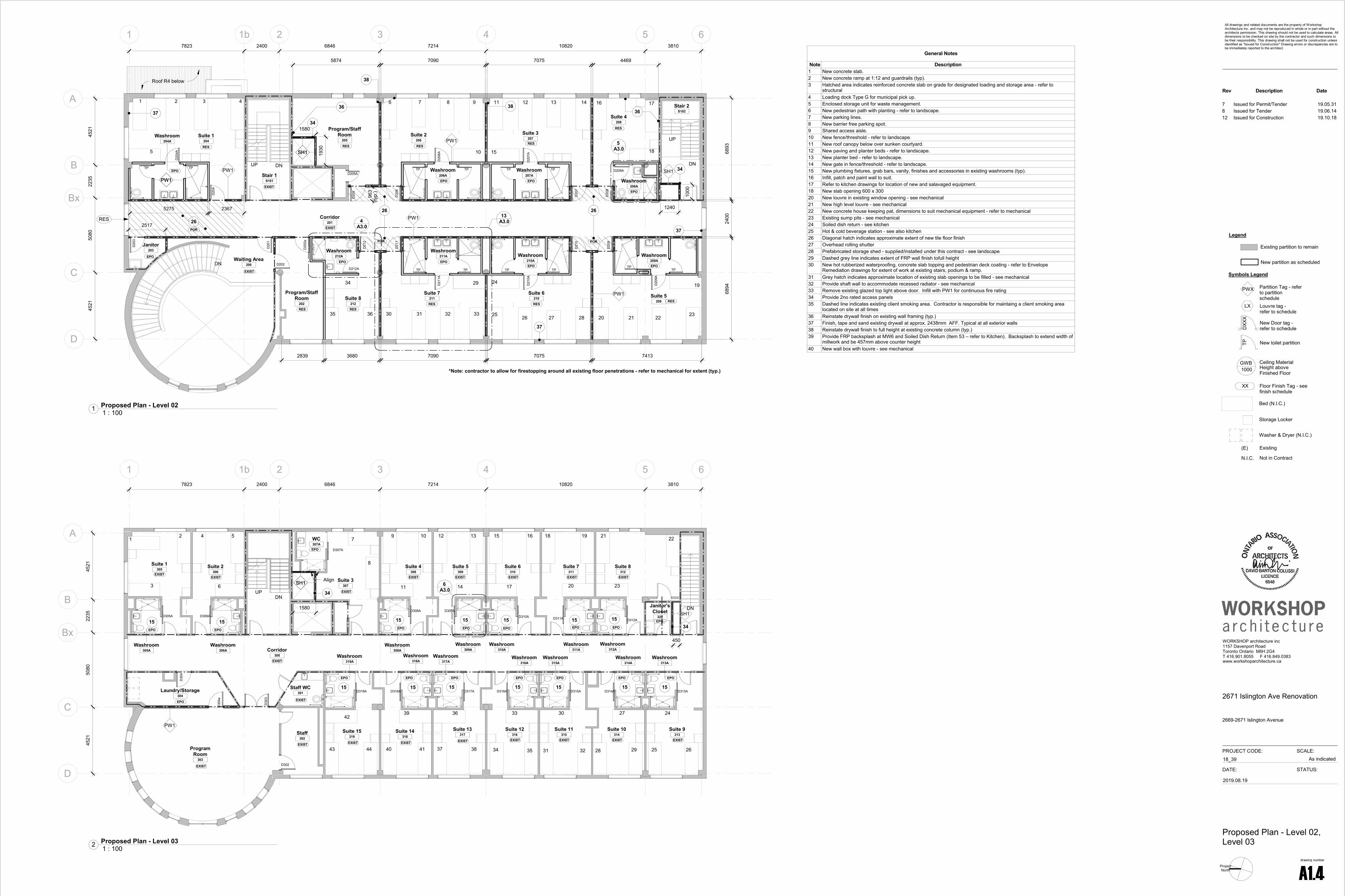
1 : 1001 Proposed Plan - Level 02
1 : 1002 Proposed Plan - Level 03
General Notes
Note Description1 New concrete slab.2 New concrete ramp at 1:12 and guardrails (typ).3 Hatched area indicates reinforced concrete slab on grade for designated loading and storage area - refer to
structural4 Loading dock Type G for municipal pick up.5 Enclosed storage unit for waste management.6 New pedestrian path with planting - refer to landscape.7 New parking lines.8 New barrier free parking spot.9 Shared access aisle.10 New fence/threshold - refer to landscape.11 New roof canopy below over sunken courtyard.12 New paving and planter beds - refer to landscape.13 New planter bed - refer to landscape.14 New gate in fence/threshold - refer to landscape.15 New plumbing fixtures, grab bars, vanity, finishes and accessories in existing washrooms (typ).16 Infill, patch and paint wall to suit.17 Refer to kitchen drawings for location of new and salavaged equipment.18 New slab opening 600 x 30020 New louvre in existing window opening - see mechanical21 New high level louvre - see mechanical22 New concrete house keeping pat, dimensions to suit mechanical equipment - refer to mechanical23 Existing sump pits - see mechanical24 Soiled dish return - see kitchen25 Hot & cold beverage station - see also kitchen26 Diagonal hatch indicates approximate extent of new tile floor finish27 Overhead rolling shutter28 Prefabricated storage shed - supplied/installed under this contract - see landscape29 Dashed grey line indicates extent of FRP wall finish tofull height30 New hot rubberized waterproofing, concrete slab topping and pedestrian deck coating - refer to Envelope
Remediation drawings for extent of work at existing stairs, podium & ramp.31 Grey hatch indicates approximate location of existing slab openings to be filled - see mechanical32 Provide shaft wall to accommodate recessed radiator - see mechanical33 Remove existing glazed top light above door. Infill with PW1 for continuous fire rating34 Provide 2no rated access panels35 Dashed line indicates existing client smoking area. Contractor is responsible for maintaing a client smoking area
located on site at all times36 Reinstate drywall finish on existing wall framing (typ.)37 Finish, tape and sand existing drywall at approx. 2438mm AFF. Typical at all exterior walls38 Reinstate drywall finish to full height at existing concrete column (typ.)39 Provide FRP backsplash at MW6 and Soiled Dish Return (Item 53 – refer to Kitchen). Backsplash to extend width of
millwork and be 457mm above counter height40 New wall box with louvre - see mechanical
Rev Description Date
7 Issued for Permit/Tender 19.05.318 Issued for Tender 19.06.1412 Issued for Construction 19.10.18

1 1b 2 3 4 5 6
A
B
Bx
C
D
4521
5080
2235
4521
ACT
2743
GWB
2438
ACT
2438
GWB
3010
C1
ACT2
2743
GWB
3912
FRP
2438 2364Exist3010
Dining HallB101
LoungeB100
OfficeB104A
VestibuleB102
Stair 2S102
Receiving/StorageB103
Walk-InCooler
B105Storage
B106Storage
B107
WorkshopB108
StaffB109
IT/ ElectricalRoom
B110
RotondaB111 Counselling
B112
HallB117
StorageB114
SprinklerRoom
B113
Staff ChangeB116A
StaffWashroom
B116B
WashroomB115
Staff LoungeB116
Stair 1S101
WasteStorage
B121
MechanicalRoom
B119
ElevatorRoom
B118
Exist
ACT
2743
ACT
2743
StorageB104B
ACT
2743
GWB
2743
Exist2384
Exist2384
Exist3010
Exist2438
Exist2438
Exist3658
C6
C6
Exist2438
ACT
2743
ACT
2438
GWB
2134
C5
4A1.5
See detail RCP for canopy
cladding layout
C7
L1 L1
400
400
600
Align with mullions
Align with columns below
3810
GWB
2438
EXP4140
GWB
3010
C8
C8
GWB
3618
1 1b 2 3 4 5 6
A
B
Bx
C
D
7823 2400 6846 7214 10820 3810
GWB
2438
ACT
3353
GWB
2438
GWB
2438
ACT
2743
ACT
2743
GWB
2438
ACT
2438
ACT
2438
GWB
2438
ACT
2743
ACT
3353ACT
3353
ACT
3353
ACT
3353
GWB
3353
ACT
3353
C2
FRP
2438
FRP
2438
FRP
2438
FRP
2438
Refer to M&E drawings for extent of ceiling mounted fixtures/devices
Provide 4 no 400x400 access panels -locations to be coordinated on site.
ACT
3658
3A1.5
Intake Room104
ACT
3353
4521
5080
2235
4521 Community
Room102
Storage102b
CommunityKitchen
102a
WellnessRoom
113
Stair 1S101 Lounge
112
Suite 1115
Suite 2116
Shared WC117
Corridor114
Shared WC120
Suite 3118
Suite 4119
UniversalSuite
121
Staff108
Staff109
Admin107
Reception103
BF WC106
Universal WC105
Waiting Area100A
Vestibule100
Corridor110
Storage123
Universal WC121A
Laundry122
GWB
2743
GWB
2743
GWB
2743
GWB
2743
C4 C4 C4
C4 C4
C4
C5
ACT
3353
IT Closet107b
ACT
2743
GWB
2079
EXP
4109
EXP
4109
EXP
4109EXP
4109
EXP
4109
C7
C7
C7
Existing partition to remain
New partition as scheduled
Legend
Symbols Legend
GWB1000
Ceiling MaterialHeight above Finished Floor
DXX
X
New Door tag -refer to schedule
(E) Existing
N.I.C. Not in Contract
Bed (N.I.C.)
Storage Locker
Washer & Dryer (N.I.C.)
Partition Tag - refer to partition schedule
PWX
New toilet partitionTP
LX Louvre tag -refer to schedule
XX Floor Finish Tag - see finish schedule
Ceiling Legend
LED lighting fixture - see electrical
Potlight - see electrical
Return/exhaust grille
Supply air diffuser
LED cove light - see electrical
Rollershade
3 4
A
B
Bx
7214
2235
4521
Lounge112
ACT
3658
GWB
3353
199 1038
(8 tiles across)
4877 1037
(8 T
iles
Acro
ss
4840
1037
Provide rollershades at all windows (typ.)
4592
EQ A EQ A EQ B EQ B
FRC
1219
1219
610
1219
3159 3341
1219
1219
610
1219
610
1219
Centre on mullion below
1219
1219
1219
1219
610
1219
ProjectNorth
PROJECT CODE: SCALE:
WORKSHOP architecture inc1157 Davenport RoadToronto Ontario M6H 2G4T 416.901.8055 F 416.849.0383www.workshoparchitecture.ca
All drawings and related documents are the property of Workshop Architecture Inc. and may not be reproduced in whole or in part without the architects permission. This drawing should not be used to calculate areas. All dimensions to be checked on site by the contractor and such dimensions to be their responsibility. This drawing shall not be used for construction unless identified as "Issued for Construction" Drawing errors or discrepancies are to be immediately reported to the architect.
drawing number
DATE: STATUS:
As indicated18_39
A1.5
2671 Islington Ave Renovation
2669-2671 Islington Avenue
Proposed RCPs -Basement, Level 01
2019.08.19
1 : 1001 Proposed RCP - Basement
1 : 1002 Proposed RCP - Level 01
Ceiling Notes
Note DescriptionC1 Sloped ceiling to match existing.C2 GWB bulkhead at ceiling transition.C3 Paint and patch existing ceilings as required to accomodate new fixtures (typ).C4 Access panel for fan coil unit (600 x 600) - refer to mechanicalC5 Bulkhead around duct work to be wall type SH1 to maintain required fire rating - refer to mechanicalC6 Approximate location of hood - refer to kitchenC7 New roller shades at all windows (typ.)C8 New GWB ceiling as required based on demolition
1 : 503 Partial RCP - Level 01 - Lounge
1 : 504 Proposed RCP - Canopy Soffit
Rev Description Date
2 Issued for Coordination 18.12.104 Issued for 50% Costing 18.12.215 Issued for Coordination 19.03.076 Issued for 75% Costing 19.04.117 Issued for Permit/Tender 19.05.318 Issued for Tender 19.06.1412 Issued for Construction 19.10.18

OS
OS
OS
1 1b 2 3 4 5 6
A
B
Bx
C
D
7823 2400 6846 7214 10820 3810
4521
5080
2235
4521
ACT
2743
GWB
2743
GWB
2743
ACT
2743
GWB
2743
GWB
2743
GWB
2743
GWB
2743
GWB
2743
GWB
2743
ACT
2743
FRP
2743
FRP
2743
FRP
2743
FRP
2743
FRP
2743
FRP
2743
FRP
2743
FRP
2743
Refer to M&E drawings for extent of ceiling mounted fixtures/devices
Provide 4 no 400x400 access panels -locations to be coordinated on site.
3A1.6
GWB
2743
GWB
2743
GWB
2743
GWB
2743
GWB
2743
GWB
2743
GWB
2743
GWB
2743
Suite 1204
Washroom204A
Janitor203
Corridor201
Program/StaffRoom
202Suite 8
212Suite 7
211Suite 6
210 Suite 5209
Washroom209A
Program/StaffRoom
205Suite 2
206Suite 3
207Suite 4
208
Washroom208A
Washroom207A
Washroom206A
Washroom212A
Washroom211A
Washroom210A
C5
EXP
3366
EXP
3366
EXP
3366
EXP
3366
EXP
3366
EXP
3366
EXP
3366
C7 C7
C7
C7
1 1b 2 3 4 5 6
A
B
Bx
C
D
7823 2400 6846 7214 10820 3810
C3
C3 C3 C3 C3 C3 C3 C3 C3
C3C3C3C3C3C3
C3C3
C3
Refer to M&E drawings for extent of ceiling mounted fixtures/devices
Provide 4 no 400x400 access panels - locations to be coordinated on site.
ACT
2743
ACT
2438
FRP
2438
GWB
2438
FRP
2438
GWB
2438
GWB
2438
FRP
2438FRP
2438
GWB
2438
FRP
2438
GWB
2438
FRP
2438
GWB
2438
FRP
2438
GWB
2438
FRP
2438
GWB
2438
GWB
2438
GWB
2438
FRP
2438
FRP
2438
FRP
2438
FRP
2438
GWB
2438
GWB
2438
GWB
2438
GWB
2438
FRP
2438FRP
2438
GWB
2438
GWB
2438
GWB
2438
GWB
2438
GWB
2438
GWB
2438
GWB
2438
GWB
2438
GWB
2438
GWB
2438
GWB
2438
GWB
2438
GWB
2438
GWB
2438
GWB
2438
4521
5080
2235
4521
Suite 1305
Suite 2306
Suite 3307
Suite 4308
Suite 5309
Suite 6310
Suite 7311
Suite 8312
Janitor'sCloset
320
ProgramRoom
303
Laundry/Storage304
Corridor300
Staff WC301
Washroom319A
Staff302
Suite 15319
Suite 14318
Suite 13317
Suite 12316
Suite 11315
Suite 10314
Suite 9313
Washroom314A
Washroom313A
Washroom315A
Washroom316A
Washroom318A
Washroom317A
Washroom305A
Washroom306A
Washroom308A
Washroom309A
Washroom310A
Washroom311A
Washroom312A
C7 C7
C7
C7
Ceiling Legend
LED lighting fixture - see electrical
Potlight - see electrical
Return/exhaust grille
Supply air diffuser
LED cove light - see electrical
Rollershade
Existing partition to remain
New partition as scheduled
Legend
Symbols Legend
GWB1000
Ceiling MaterialHeight above Finished Floor
DXX
X
New Door tag -refer to schedule
(E) Existing
N.I.C. Not in Contract
Bed (N.I.C.)
Storage Locker
Washer & Dryer (N.I.C.)
Partition Tag - refer to partition schedule
PWX
New toilet partitionTP
LX Louvre tag -refer to schedule
XX Floor Finish Tag - see finish schedule
3 4
C
D
GWB
2743
FRP
2743
Washroom211A
Suite 7211
Access Panel
Occupancy sensor
GWB
2743
Bulkhead
7214
4521
1118
Site verify - to conceal primary services
EQEQ
EQ EQ
EQEQ
EQ EQ
Rolleshades (typ.)
EQ EQ EQ EQ
ProjectNorth
PROJECT CODE: SCALE:
WORKSHOP architecture inc1157 Davenport RoadToronto Ontario M6H 2G4T 416.901.8055 F 416.849.0383www.workshoparchitecture.ca
All drawings and related documents are the property of Workshop Architecture Inc. and may not be reproduced in whole or in part without the architects permission. This drawing should not be used to calculate areas. All dimensions to be checked on site by the contractor and such dimensions to be their responsibility. This drawing shall not be used for construction unless identified as "Issued for Construction" Drawing errors or discrepancies are to be immediately reported to the architect.
drawing number
DATE: STATUS:
As indicated18_39
A1.6
2671 Islington Ave Renovation
2669-2671 Islington Avenue
Proposed RCPs - Level 02,Level 03
2019.08.19
1 : 1001 Proposed RCP - Level 02
1 : 1002 Proposed RCP - Level 03
Ceiling Notes
Note DescriptionC1 Sloped ceiling to match existing.C2 GWB bulkhead at ceiling transition.C3 Paint and patch existing ceilings as required to accomodate new fixtures (typ).C4 Access panel for fan coil unit (600 x 600) - refer to mechanicalC5 Bulkhead around duct work to be wall type SH1 to maintain required fire rating - refer to mechanicalC6 Approximate location of hood - refer to kitchenC7 New roller shades at all windows (typ.)C8 New GWB ceiling as required based on demolition
1 : 503 Partial RCP - Level 02 - Typical Suite
Rev Description Date
7 Issued for Permit/Tender 19.05.318 Issued for Tender 19.06.1412 Issued for Construction 19.10.18

Level 1
150300
Level 2
154669
Level 3
158326
Roof - Lower
161527
Roof - Upper
164575
Basement
145931
11b23456
South East Grade
148620North East Grade
147700
existing building
1769
2600
4369
3658
3200
Average Grade: 148650
3048
Refer to Envelope Remediation drawings for envelope repair (typ.)
Excavated area at new ramp/sunken courtyard shown dotted - see details
New handrail/ guardrail - see details
New louvre - see mechanical (typ.)
Level 1
150300
Level 2
154669
Level 3
158326
Roof - Lower
161527
Roof - Upper
164575
1 1b 2 3 4 5 6
West Grade
149100
3200
3658
4369
1200
existing building
Average Grade: 148650
3048
Refer to Envelope Remediation drawings for envelope repair (typ.)
Existing guard to remain
ProjectNorth
PROJECT CODE: SCALE:
WORKSHOP architecture inc1157 Davenport RoadToronto Ontario M6H 2G4T 416.901.8055 F 416.849.0383www.workshoparchitecture.ca
All drawings and related documents are the property of Workshop Architecture Inc. and may not be reproduced in whole or in part without the architects permission. This drawing should not be used to calculate areas. All dimensions to be checked on site by the contractor and such dimensions to be their responsibility. This drawing shall not be used for construction unless identified as "Issued for Construction" Drawing errors or discrepancies are to be immediately reported to the architect.
drawing number
DATE: STATUS:
1 : 10018_39
A2.0
2671 Islington Ave Renovation
2669-2671 Islington Avenue
Elevations
2019.08.19
1 : 1002 East Elevation
1 : 1001 West Elevation
Rev Description Date
1 Issued for PPR/ZC 18.11.262 Issued for Coordination 18.12.103 Pre-SPA Consultation 18.12.124 Issued for 50% Costing 18.12.215 Issued for Coordination 19.03.076 Issued for 75% Costing 19.04.117 Issued for Permit/Tender 19.05.318 Issued for Tender 19.06.1412 Issued for Construction 19.10.18

Level 1
150300
Level 2
154669
Level 3
158326
Roof - Lower
161527
Roof - Upper
164575
A B Bx C D
West Grade
149100
North East Grade
147700
3200
3658
4369
existing building
Average Grade: 148650
New canopy
3048
Reter to Envelope Remediation drawings for envelope repair (typ.)
2600
Connect gutter in to existing RWL
New louvre - see mechanical (typ.)
Level 1
150300
Level 2
154669
Level 3
158326
Roof - Lower
161527
Roof - Upper
164575
ABBxCD
West Grade
149100 South East Grade
148620
existing building
Average Grade: 148650
build
ing
heig
ht
1671
4
3200
3658
4369
1680
New canopy
3048
Reter to Envelope Remediation drawings for envelope repair (typ.)
Guardrail G1PROJECT CODE: SCALE:
WORKSHOP architecture inc1157 Davenport RoadToronto Ontario M6H 2G4T 416.901.8055 F 416.849.0383www.workshoparchitecture.ca
All drawings and related documents are the property of Workshop Architecture Inc. and may not be reproduced in whole or in part without the architects permission. This drawing should not be used to calculate areas. All dimensions to be checked on site by the contractor and such dimensions to be their responsibility. This drawing shall not be used for construction unless identified as "Issued for Construction" Drawing errors or discrepancies are to be immediately reported to the architect.
drawing number
DATE: STATUS:
1 : 10018_39
A2.1
2671 Islington Ave Renovation
2669-2671 Islington Avenue
Elevations
2019.08.19
1 : 1001 North Elevation
1 : 1003 South Elevation
Rev Description Date
7 Issued for Permit/Tender 19.05.318 Issued for Tender 19.06.1412 Issued for Construction 19.10.18

2 3 4
C
D
D107
D105
D106
D10
4
D104a
6846 7214
75272765
3250
3350
1062 x 716heat tent
Washer/Dryer(N.I.C)
D109
D108
D10
9a
D103
Staff109
Staff108
Intake Room104
Admin107
Reception103
Universal WC105
BF WC106
3223
2574 2350
3796
D10
7a
4521
PW1PW1
PW1
PW1PW1
PW1
4600 1350 3219 62
MW2
PW1
460
810
Space for adult change table
Clear space 920 x 1370
Transfer space 900 x 1500
ø 1700
PW1
PW1
PW1a
Transfer space 900 x 1500
674 1900
A3.1 4
A3.1
7
MW3 959
Clear space 920 x 1370
900
711
4A3.2
10A3.2
1500
A3.1
18
19
20
1987
IT Closet107b
D10
7b
2644
Photocopier N.I.C
A3.1
6
A3.1
23
21
22
460
24Power door operator
5
276
1990
610
861
1738
5A3.2 Provide gromet - see
millwork hardware legendProvide gromet - see millwork hardware legend
PW1
RES
RES2
EPO
EXIST
RESPOR
EPO
15561373
align
Fridge supplied/installed under this contract
3 4
A
B
Bx
WellnessRoom
113Lounge
112
Washroom111
2235
4521
D113
6011 6952 62
D111
PW1 PW1
7214
460
460
PW1
PW1
FW1
PW1aalign
A3.1
9
MW5
6A3.2
FW1
FW1
SH1SH1SH1 RES2EPO
Align
500
500
B
Bx
A3.1
10
2400
1600
Clearspace 920x1370
EQ EQ
11
12
13
2400
460
ø 1500
ø 1500
D116aD115a
2329
1104
3433
PW1
PW1PW1
PW1
EPO RES
5 6
C
D12
1A
ø 2500 Space for
adult change table
Transfer space 900x1500
Clearspace 920x1370
1500
3810
922
2933
3855
PW1
PW1
FW1
900
1674
A3.1 16
Universal WC121A
14
15
Power door operator
460
17
3 4
C
D
305
2400
D21
1A
D21
1
Suite 7211
Washroom211A
709
460
1500 1500
4370
(Varies)
7090
4521
A3.1
25
26
PW1
27 A3.1 28PW1
1387
1573 5275
PW1
PW1
(varies)365
PW1
PW1
PW1
FW1
EPO
RES
5
B
Bx
Washroom208A
PW1
PW1D208A
2235
PW1
PW1
2065 785
W6W8
W2 4
B
BxWashroom
309A
D309AA3.130 29
31
32EPOEXIST
1
B
Bx
D102
D10
2b
Storage102b
CommunityRoom
102
EQEQ
1140
5300
MW5
2235
PW1
PW1
A3.1
8
3900
Reception sliding window to be temporarily placed during phase one. Phase 2: remove and salvage for reuse in admin area. Patch and make good adjacent surfaces
7A3.2
9A3.2
8A3.2
All kitchen appliances supplied/installed under this contract
1 1b
Staff ChangeB116A
WashroomB115
StaffWashroom
B116B
Staff ShowerB116C
DB1
16A
DB115
460
DB1
16
1500
1500
2175 2340 1500
PW1PW1
PW1PW1
ø 1500
460
Staff LoungeB116
FW1
PW1
7823
MW1
DB1
16B
PW2
A3.11
DB116C
DB116D
1A3.2
RES
EXIST
EXISTEPO
1 1b
A
Existing RWLto remain
2A4.3
WasteStorage
B121
EDB1
21
Align
Align
DB1
21A
13A4.3
3000
EW2
EW2Line of masonry below
L3
L3
PW2
Existing partition to remain
New partition as scheduled
Legend
Symbols Legend
GWB1000
Ceiling MaterialHeight above Finished Floor
DXX
X
New Door tag -refer to schedule
(E) Existing
N.I.C. Not in Contract
Bed (N.I.C.)
Storage Locker
Washer & Dryer (N.I.C.)
Partition Tag - refer to partition schedule
PWX
New toilet partitionTP
LX Louvre tag -refer to schedule
XX Floor Finish Tag - see finish schedule
3
C
Washroom212A
D212A
460
14493069
D21
2
900
1500
777
ø 1500
PW1
PW1
W6
W2
W8
EPO RES
A3.12
Dining HallB101
3000
610
MW6
914
New location of bottle filler - refer to mechanical
Drop-in glass dispenser -Refer to Kitchen
Hot and cold beverage counter - refer to kitchen
2A3.2
Min
.
900
Provide FRP backsplash at MW6 and Soiled Dish Return (Item 53 –refer to Kitchen). Backsplash to extend width of millwork and be 457mm above counter height
A3.1 3
3A3.2
62
Overhead shutter
DB104b
HSS Post -refer to structural
KitchenB104
Dining HallB101
Hot food counter -refer to kitchen
DB104e
HSS Post -refer to structural
ProjectNorth
PROJECT CODE: SCALE:
WORKSHOP architecture inc1157 Davenport RoadToronto Ontario M6H 2G4T 416.901.8055 F 416.849.0383www.workshoparchitecture.ca
All drawings and related documents are the property of Workshop Architecture Inc. and may not be reproduced in whole or in part without the architects permission. This drawing should not be used to calculate areas. All dimensions to be checked on site by the contractor and such dimensions to be their responsibility. This drawing shall not be used for construction unless identified as "Issued for Construction" Drawing errors or discrepancies are to be immediately reported to the architect.
drawing number
DATE: STATUS:
As indicated18_39
A3.0
2671 Islington Ave Renovation
2669-2671 Islington Avenue
Partial Plans
2019.08.19
1 : 509 Partial Plan - Level 01 - Intake Sequence1 : 508Partial Plan - Level 01 - Client Lounge, WellnessRoom, BF WC
1 : 502 Partial Plan - Level 01 Shared BF WC (Typical)1 : 503 Partial Plan - Level 01 Universal WC
1 : 5013 Partial Plan - Level 02 - Typical Suite
1 : 505 Partial Plan - Level 02 WC 208A1 : 506 Partial Plan - Level 03 WC (Typical)
1 : 507 Partial Plan - Level 01 - Community Room
1 : 501 Partial Plan - Basement - Staff Changeroom, BF WC
1 : 5010 Partial Plan - Grade - Waste Storage Room
1 : 504 Parital Plan - Level 02 WC 212A1 : 5011 Partial Plan - Basement - Beverage Counter
1 : 5014 Patial Plan - Basement - Hot Food Counter
Rev Description Date
6 Issued for 75% Costing 19.04.117 Issued for Permit/Tender 19.05.318 Issued for Tender 19.06.1411 Reissued for Permit 19.08.2212 Issued for Construction 19.10.18

T/O Finished Floor
4'-0" AFF
3'-0" AFF
(600
mm
)
min
2'-0
"
toilet paper dispenser
(100
0 m
m)
max
3'-3
3/8
"
Notes:1. All controls (power door operator, elevator call buttons, fire alarms, switches, emergency call button and fire extinguishers, coat hooks etc.) to be between 3' and 4' AFF.2. Locations of all accessories and controls to be marked on site prior to installation for final sign off.
(760 mm)
min. 30"
(max300 mm, min 60mm)
max 1'-0", min 0'- 2 3/8"
mirrors in universal washrooms
(760
mm
)
min
. 30"
(750
-950
mm
)
29" t
o 37
"
(150 mm)89
soap dispenser
grab bars
C/L
(600 mm)
min. 2'-0"
33" t
o 36
"
grab bars behind toiletsgrab bars and wc accessories
beside toilets
IN THE EVENT OF AN EMERGENCY PUSH EMERGENCY BUTTON AND AUDIBLE AND VISUAL SIGNAL WILL ACTIVATE
Hanging Schedule
(840
-920
mm
)
push buttoncoat hook
sinks in universal washrooms
735m
m
min
2' -
4 1
5/16
"
accessible strip emergency call
373m
m
max
1' -
2"
handryer
FRP FRP
W4a
W4b
W4a
W4b
W6
W3
W7
W8
EPO
W6
W4a
W4b
FRP
EPO
FRP
W3
EQ EQ
W5 W4a
W1 W1W9W2 W9
EPO
FRP
Level 1
150300
FRP
W10
W11W4b
W4a
FRP
EPO
Materials Legend
ACT Acoustic Ceiling TileCMU Concrete Masonry (Painted)CICS Continuous Insulation Cladding
SystemEPO Epoxy EXIST ExistingEXP ExposedFRP Fiberglass Reinforced Panel GWB Gypsum Wallboard (Painted)PAV Concrete PaversPOR Porcelain TilePRG Concrete PargingPLAM Plastic LaminatePT Paint FinishPV Paving Stones RB Rubber BaseRES Resilient FlooringSCW Solid Core WoodSOL Solid SurfaceSP Solid Phenolic Toilet PartitionsSS Stainless SteelTGL Tempered Glass
Level 2
154669
W1
W9
W1
W4b
W4b
W5
FRP
EPO
W3
W6
W4a
EQEQ
W9
W4a
33A3.1
102
W2FRP
FRP
EPO
2743
Toile
t Par
titio
n
1981
152
102
FRP
W4a
W4b
W6
W3
W7
W8
EPO
102 Level 2
154669
FRP
W4a
W4b
EPO10
2
Existing partition to remain
New partition as scheduled
Legend
Symbols Legend
GWB1000
Ceiling MaterialHeight above Finished Floor
DXX
X
New Door tag -refer to schedule
(E) Existing
N.I.C. Not in Contract
Bed (N.I.C.)
Storage Locker
Washer & Dryer (N.I.C.)
Partition Tag - refer to partition schedule
PWX
New toilet partitionTP
LX Louvre tag -refer to schedule
XX Floor Finish Tag - see finish schedule
Level 1
150300
Microwave
CooktopBuilt-in oven
FRP
7A3.2
9A3.2
Site Verify
648
8A3.2
Range hood
750 950 650 750 800
PT
SOL
Level 1
150300
4A3.2
1750
860
1324
Level 1
150300
Photocopier (N.I.C)
10A3.2
Basement
145931
fixedfixed drawer drawer
FRP
PT
1A3.2
Site Verify
770EQ EQ
W4a
W4b
FRP
W10W11
space for fold down adult change table
1080
1219min.
406
min.
406
EPO
Hatched area indicates approx. extent of 19mm plywood blocking
Level 1
150300
FRPW7W8
W3
W6
W4b
W4a
W4b
W4a
EPO
IN THE EVENT OF AN EMERGENCY PUSH EMERGENCY BUTTON AND AUDIBLE AND VISUAL SIGNAL WILL ACTIVATE Emergency
light strip - see electrical
34A3.1
FRP to wrap existing column
FRP
EPO
W3EQ EQ
W1 W9
W4b
W4a
W6
W5W4a
GWB partition
Existing slabMortar bed
FRP panel
FRP seal
waterproof membrane
102
over
lap
51
25
Liquid applied epoxy flooring
Carry continuous waterproof membrane as specified up full height of wall behind FRP panel (typ.)
drain
polyethylene backer rod
over
lap
5110
2
centreline of shower
25
edge of shower
25
FRP panel
FRP seal
Liquid applied flooring
waterproof membrane
centreline of external area
drain
waterproof membrane polyethylene
backer rod
over
lap
5110
225
FRP panel
FRP seal
Liquid applied flooring
waterproof membrane
Mortar bed Mortar bed
Level 1
150300
Power door operator
W2
EPO
FRP
New location of existing botter filler - Refer to mechanical
EQ EQ EQ
Hot/cold beverage counterRefer also to kitchen
2A3.2
FRP 457
3000
Level 1
150300
FRP
W10
W4b
W4a
W11
EPO
FRP
EPO
W4b
W4a
W3
W6
W4b
W4aW7 W8
W6
W4a
W4b
W3
W5 W4a
FRP
EQEQ
EPO
381381976
5A3.2
FRPspace for fold down adult change table
min.
406
min.
406
EPO
Power door operator Hatched area indicates
approx. extent of 19mm plywood blocking
IN THE EVENT OF AN EMERGENCY PUSH EMERGENCY BUTTON AND AUDIBLE AND VISUAL SIGNAL WILL ACTIVATE
Emergency light strip - see electrical
EPO
FRP
W4b
W4aW4a
W4b
FRP
W10W11
EPO
W2
Fixed Fixed
PT
6A3.2
Level 1
150300
FRP
EPO
W1
W9
Level 3
158326
W3
W4b
W4a
EPO
FRP
Level 3
158326
34A3.1
W1
W9W3
W4b
W4a
EPO
W4a
W4aFRP
Level 3
158326
EPO
102
FRP
W4a
W4bW4a
W3
Level 3
158326
EPO
102
FRP
W4a
W4b
W11
W10
Basement
145931
Hot food counter - refer to kitchen
3A3.2
SOL
4A3.2
1750
860
1324
PROJECT CODE: SCALE:
WORKSHOP architecture inc1157 Davenport RoadToronto Ontario M6H 2G4T 416.901.8055 F 416.849.0383www.workshoparchitecture.ca
All drawings and related documents are the property of Workshop Architecture Inc. and may not be reproduced in whole or in part without the architects permission. This drawing should not be used to calculate areas. All dimensions to be checked on site by the contractor and such dimensions to be their responsibility. This drawing shall not be used for construction unless identified as "Issued for Construction" Drawing errors or discrepancies are to be immediately reported to the architect.
drawing number
DATE: STATUS:
As indicated18_39
A3.1
2671 Islington Ave Renovation
2669-2671 Islington Avenue
Interior Elevations & Details
2019.08.19
Washroom Accessories
Note DescriptionW1 457 x 762 mirrorW2 Hand dryerW3 Shower curtain & rodW4a Grab barW4b 'L' shaped grab barW5 250 x 250 recessed soap holderW6 Fold down shower seatW7 Coat hooksW8 ShelfW9 Soap dispenser - Owner supplied contractor installedW10 Napkin disposal - Owner supplied contractor installedW11 Toilet paper dispenser - Owner supplied contractor installed
1 : 5010 Interior Elevation - Level 01 Typ. Shared WC - East1 : 5011 Interior Elevation - Level 01 Typ. Shared WC - South
1 : 5012 Interior Elevation - Level 01 Typ. Shared WC - West1 : 5013 Interior Elevation - Level 01 Typ. Shared WC - North
1 : 5025 Interior Elevation - Level 02 Typ. Suite WC - East1 : 5026 Interior Elevation - Level 02 Typ. Suite WC - South
1 : 5027 Interior Elevation - Level 02 Typ. Suite WC - North1 : 5028 Interior Elevation - Level 02 Typ. Suite BF Toilet
1 : 508 Interior Elevation - Level 01 - MW4
1 : 504 Interior Elevation - Level 01 - MW2 - South1 : 507 Interior Elevation - Level 01 - MW3
1 : 501 Interior Elevation - Basement - MW1
1 : 5016Interior Elevation - Level 01 - Universal WC121A -South
1 : 5014Interior Elevation - Level 01 - Universal WC121A -East
1 : 5015Interior Elevation - Level 01 - Universal WC121A -North
1 : 533 Detail - Cove Base (typ.)1 : 534 Detail - Shower Floor (typ.)
1 : 5017Interior Elevation - Level 01 - Universal WC121A -West
1 : 502 Interior Elevation - Basement - MW6
1 : 5018 Interior Elevaton - Level 01 - BF WC 106 - West1 : 5019 Interior Elevation - Level 01 - BF WC 106 - North
1 : 5020 Interior Elevation - Level 01 - BF WC 106 - East
1 : 506 Interior Elevation - Level 01 - MW2 - West
1 : 5021 Interior Elevation - Level 01 - Universal WC105 - East1 : 5022Interior Elevation - Level 01 - Universal WC105 -South
1 : 5023Interior Elevation - Level 01 - Universal WC105 -West
1 : 509 Interior Elevation - Level 01 - MW5
1 : 5024Interior Elevation - Level 01 - Universal WC105 -North
1 : 5030 Interior Elevation - Level 03 Typ. Suite WC-North1 : 5029 Interior Elevation - Level 03 Typ. Suite WC - South
1 : 5031 Interior Elevation - Level 03 Typ. Suite WC - East1 : 5032 Interior Elevation - Level 03 Typ. Suite WC - West
1 : 503 Interior Elevation - Basement - Hot Food Counter1 : 505 Interior Elevation - Level 01 - MW2 - North
Rev Description Date
6 Issued for 75% Costing 19.04.117 Issued for Permit/Tender 19.05.318 Issued for Tender 19.06.1412 Issued for Construction 19.10.18

Level 1
150300
Solid surface gable beyond
585 25
860
25125
610
102
Reception103
Waiting Area100A
Solid surface countertop (mitred edge) typ.
Rubber base
Reception window - see millwork hardware legend
Solid surface finish
Level 1
150300
Solid surface counter (mitred edge) typ.
Plam at all door/drawer faces (typ)
Include one adjustable Plam shelf per lower cabinet (typ)
Plam
509
457
812
102
Hardware as specified
Rubber Base
Drawer
457
635
1880
Basement
145931
Dining HallB101
KitchenB104
Act Ceiling
Existing GWB ceiling
Line of overhead door
Hot food counter -refer to kitchen
Soild surface
Line of wall beyond
HSS post beyond -refer to structural
Mounting plate beyond - refer to structural
Basement
145931
Hardware as specified
Plam finish at all door faces (typ.)
Include two adjustable plam shelves at all upper cabinets unless noted otherwise
Plam finish at upper cabinet interiors (typ.)
914
Solid surface countertop (mitred edge) typ.
3877
510
2
Include one adjustable plam shelf at all lower cabinets unless noted otherwise
Hardware as specified
Rubber base
25
Plam finish at all door faces (typ.)
Plam finish at lower cabinet interiors (typ.)
635
305
Materials Legend
ACT Acoustic Ceiling TileCMU Concrete Masonry (Painted)CICS Continuous Insulation Cladding
SystemEPO Epoxy EXIST ExistingEXP ExposedFRP Fiberglass Reinforced Panel GWB Gypsum Wallboard (Painted)PAV Concrete PaversPOR Porcelain TilePRG Concrete PargingPLAM Plastic LaminatePT Paint FinishPV Paving Stones RB Rubber BaseRES Resilient FlooringSCW Solid Core WoodSOL Solid SurfaceSP Solid Phenolic Toilet PartitionsSS Stainless SteelTGL Tempered Glass
860
914
2510
2
Solid surface countertop (mitred edge) typ.
Rubber base
Plam finish at all door faces (typ.)
Hardware as specified
622128
Plam finish at lower cabinet interiors (typ.)
Level 1
150300
Line of wall beyond
Fixed panel
Rubber base
775
102
Hardware as specified
Solid surface countertop (mitred edge) typ.
Include one adjustable plam shelf at all lower cabinets unless noted otherwise
Plam finish at all door faces (typ.)
Plam finish at lower cabinet interiors (typ.)
914
25
38
635
Millwork Hardware Legend
Bumpers: 2 each per door: Richelieu No 2291/2292-180 nickel finish at 2" centres or approved equivalent
Cabinet Locks: Hafele 232.35.301 or approved equivalent (all cabinets to be lockable/keyed alike unless noted otherwise)
Drawer Locks (Typical): Hafele 234.76.701 or approved equivalent (all drawers to be lockable/keyed alike unless noted otherwise)
Drawer Locks (at MW2): Hafele 234.76.700 or approved equivalent (keyed to differ)
Cabinet/Drawer Pulls:Richelieu Catalogue No 245170 or approved equivalent
Drawer guides: Blum WEBKIT1058762 orapproved equivalent
Concealed Hinges: Blum Blumotion 110 degrees or approved equivalent
Adjustable shelf pins/ferrules: Richelieu No 2291/2292-180 nickel finish at 2” centres.
Grommets: Richelieu Catalogue No 60952140 or approved equivalent (2 in total at MW2)
Reception window: Satin Anodized DW Series Manual Sliding Service WindowDW1800A XO c/w 1/2" thick tempered, laminated glass and keyed lockBy CR Laurence
Level 1
150300
860
3872
010
2
711
Solid surface desktop(mitreed edge) typ.
Drawer
Hardware as specified -locks keyed to differ
2576
245
738
822
Hardware as specified
Plam finish at all door faces (typ.)
Include two adjustable plam shelves at all upper cabinets unless noted otherwise
Plam finish at upper cabinet interiors (typ.)
Solid surface counter(mitred edge) typ.
Plam gable beyond
2079
305
GWB bulkhead
685
205
350
480
Barrier free clearances
Solid surface backsplash
FRP panel
Rubber base
140
Fixed panel, Plam finish
762
306
Site
Ver
ify
711
198
102
2079
Wall Oven - Refer to Kitchen
610
Rubber Base
Drawer
Hardware as specified
Hardware as specified
Plam finish at all door faces (typ.)
Include two adjustable plam shelves at all upper cabinets unless noted otherwise
Plam finish at upper cabinet interiors (typ.)
Open shelf
Plam
GWB bulkhead
30576
245
740
035
910
2
2079
Microwave - Refer to Kitchen
Drawer
Harware as specified
Rubber Base
Solid surface counter(mitred edge) typ.
Hardware as specified
Plam finish at all door faces (typ.)
Include two adjustable plam shelves at all upper cabinets unless noted otherwise
Plam finish at upper cabinet interiors (typ.)
GWB bulkhead
Solid surface backsplash
ProjectNorth
PROJECT CODE: SCALE:
WORKSHOP architecture inc1157 Davenport RoadToronto Ontario M6H 2G4T 416.901.8055 F 416.849.0383www.workshoparchitecture.ca
All drawings and related documents are the property of Workshop Architecture Inc. and may not be reproduced in whole or in part without the architects permission. This drawing should not be used to calculate areas. All dimensions to be checked on site by the contractor and such dimensions to be their responsibility. This drawing shall not be used for construction unless identified as "Issued for Construction" Drawing errors or discrepancies are to be immediately reported to the architect.
drawing number
DATE: STATUS:
As indicated18_39
A3.2
2671 Islington Ave Renovation
2669-2671 Islington Avenue
Section Details
2019.08.19
1 : 104 Millwork Section - MW2 - North South
1 : 1010 Millwork Section - MW3
1 : 103 Detail Section - Hot Food Counter1 : 101 Millwork Section - MW1
1 : 102 Millwork Section - MW6
1 : 106 Millwork Section - MW5
1 : 105 Millwork Section - MW2 - East West
1 : 107 Millwork Section - MW4 - Sink1 : 109 Millwork Setion - MW4 - Wall Oven
1 : 108 Millwork Section - MW4 - Microwave
Rev Description Date
7 Issued for Permit/Tender 19.05.318 Issued for Tender 19.06.1412 Issued for Construction 19.10.18

1 1b 2 3 4 5 6
A
B
Bx
C
D
7823 2400 6846 7214 10820 3810
4521
5080
2235
4521
CorridorP100 Penthouse
P101
Stair 1S101
Attic Area (vented)
Line of roof cover above
Roof R1
Elevator Cover
Refer to M&E drawings for extent of ceiling mounted fixtures/devices
Provide 4 no 400x400 access panels - locations to be coordinated on site.
3A4.3
4A4.3
EW3 EW3 EW3 EW3
EW3 EW3 EW3 EW3
RD
RD
Line of roof cover above
2% slope
2% slope
2% s
lope
2% s
lope
5A4.3
12A4.3
14A4.3
1 1b 2 3 4 5 6
A
B
Bx
C
D
Open to below
7823 2400 6846 7214 10820 3810
6A4.3
1A4.3
RD7
A4.3
Roof R2
Roof R1
2% slope 2% slope
2%
slop
e
2%
slop
e
RD2% slope 2% slope
2%
slop
e
2%
slope
8A4.3
4521
5080
2235
4521
12A4.3
14A4.3
1
A
2A4.3
Roof R4
13A4.3
Existing RWLto remain
RWL to connect in to existing
ProjectNorth
PROJECT CODE: SCALE:
WORKSHOP architecture inc1157 Davenport RoadToronto Ontario M6H 2G4T 416.901.8055 F 416.849.0383www.workshoparchitecture.ca
All drawings and related documents are the property of Workshop Architecture Inc. and may not be reproduced in whole or in part without the architects permission. This drawing should not be used to calculate areas. All dimensions to be checked on site by the contractor and such dimensions to be their responsibility. This drawing shall not be used for construction unless identified as "Issued for Construction" Drawing errors or discrepancies are to be immediately reported to the architect.
drawing number
DATE: STATUS:
As indicated18_39
A4.0
2671 Islington Ave Renovation
2669-2671 Islington Avenue
Roof Plans
2019.08.19
1 : 1001 Proposed Plan - Lower Roof
1 : 1002 Proposed Plan - Upper Roof
1 : 503 Waste Storage Room Roof Plan
Rev Description Date
7 Issued for Permit/Tender 19.05.318 Issued for Tender 19.06.1412 Issued for Construction 19.10.18
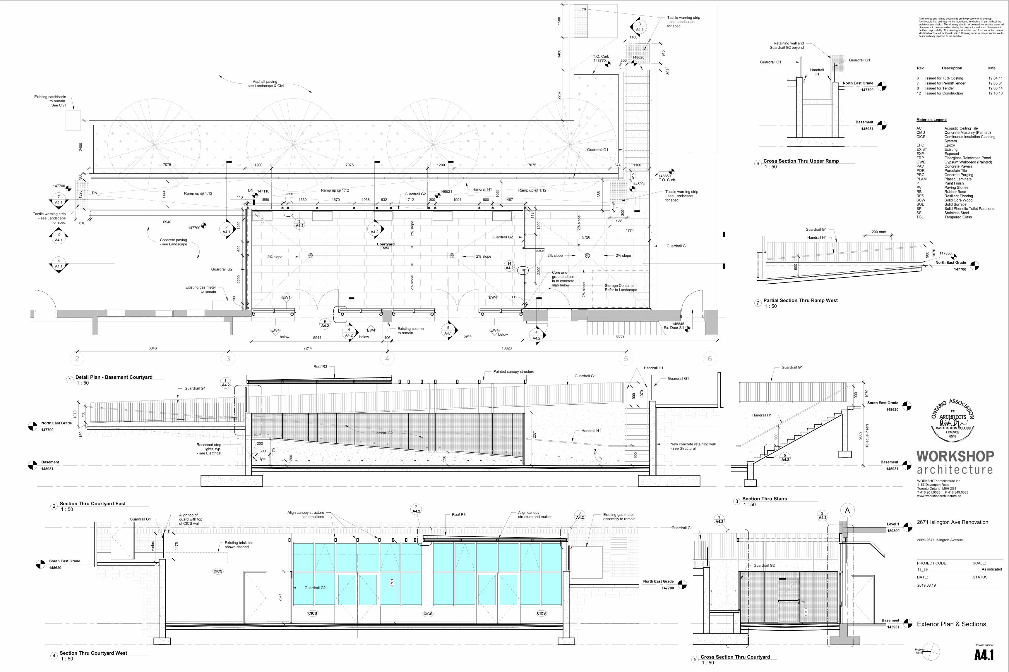
DNDN
DN
2 3 4 5 6
Ramp up @ 1:12 Ramp up @ 1:12
1200 7075 1200 7075 674 1100
Ramp up @ 1:12
CourtyardB000
6846 7214 10820
5726
2400
17742
A4.1
3A4.1
Existing column to remain
Storage Container -Refer to Landscape
Guardrail G1
Guardrail G1
5A4.1
148620
146521147110147700
1A4.2
147700
Existing gas meter to remain
Concrete paving- see Landscape
FD FD FD
148850T.O. Curb
9A4.2
Guardrail G2
Guardrail G2
Guardrail G2
4A4.2
4A4.1
145931
148845Ex. Door Sill
6A4.1
1385
148770
1144
3A4.2
5944 8839
300
2200
200
600
1490
1320
Existing catchbasin to remain.See Civil
6A4.2
112
112
Handrail H1
7A4.1
EW1
EW4
EW4
EW4EW4
below below below5944 406
Asphalt paving- see Landscape & Civil
768610
Tactile warning strip- see Landscape
for spec
Tactile warning strip- see Landscape for spec
915
1100
304
1500
1480
2287
7075
T.O. Curb
2% s
lope
2% s
lope
2% s
lope
2% s
lope
2% slope2% slope 2% slope 2% slope
1059
300
Tactile warning strip- see Landscape for spec
2200
1200
DB000
1580250
1330 1670 1038 632 1712 300 1994 600 1487
300
415
14A4.2
6940
113
235
Core and grout end bar in to concrete slab below
Basement
145931
North East Grade
147700
Painted canopy structure
New concrete retaining wall - see Structural
Guardrail G1Guardrail G11
A4.2
Handrail H1
324
150
750
1179
2371
1070
1070
Handrail H1
Guardrail G1
Guardrail G2
Roof R3
900
900
590
Recessed step lights, typ.
- see Electricaltyp.
600
200
200
Basement
145931
South East Grade
148620
16 e
qual
rise
rs
2689
Guardrail G1
5A4.2
900
Handrail H1
1070
900
Level 1
150300
Basement
145931
A2A4.21
A4.2
Guardrail G2
Guardrail G1
1010
South East Grade
148620
North East Grade
147700
CICS
2371
Existing gas meter assembly to remain
CICS CICS CICS
3701
Existing brick line shown dashed
7A4.2 8
A4.2Align canopy structure
and mullionsAlign canopy structure and mullionRoof R3
Guardrail G2
Guardrail G1
varie
s
1175
Align top of guard with top of CICS wall
Materials Legend
ACT Acoustic Ceiling TileCMU Concrete Masonry (Painted)CICS Continuous Insulation Cladding
SystemEPO Epoxy EXIST ExistingEXP ExposedFRP Fiberglass Reinforced Panel GWB Gypsum Wallboard (Painted)PAV Concrete PaversPOR Porcelain TilePRG Concrete PargingPLAM Plastic LaminatePT Paint FinishPV Paving Stones RB Rubber BaseRES Resilient FlooringSCW Solid Core WoodSOL Solid SurfaceSP Solid Phenolic Toilet PartitionsSS Stainless SteelTGL Tempered Glass
Basement
145931
North East Grade
147700
Retaining wall and Guardrail G2 beyond
Guardrail G1
Handrail H1
Guardrail G1
North East Grade
147700
147850
Handrail H1
Guardrail G1
1070
900
900
1200 max.
ProjectNorth
PROJECT CODE: SCALE:
WORKSHOP architecture inc1157 Davenport RoadToronto Ontario M6H 2G4T 416.901.8055 F 416.849.0383www.workshoparchitecture.ca
All drawings and related documents are the property of Workshop Architecture Inc. and may not be reproduced in whole or in part without the architects permission. This drawing should not be used to calculate areas. All dimensions to be checked on site by the contractor and such dimensions to be their responsibility. This drawing shall not be used for construction unless identified as "Issued for Construction" Drawing errors or discrepancies are to be immediately reported to the architect.
drawing number
DATE: STATUS:
As indicated18_39
A4.1
2671 Islington Ave Renovation
2669-2671 Islington Avenue
Exterior Plan & Sections
2019.08.19
1 : 501 Detail Plan - Basement Courtyard
1 : 502 Section Thru Courtyard East 1 : 503 Section Thru Stairs
1 : 505 Cross Section Thru Courtyard1 : 504 Section Thru Courtyard West
1 : 506 Cross Section Thru Upper Ramp
1 : 507 Partial Section Thru Ramp West
Rev Description Date
6 Issued for 75% Costing 19.04.117 Issued for Permit/Tender 19.05.318 Issued for Tender 19.06.1412 Issued for Construction 19.10.18
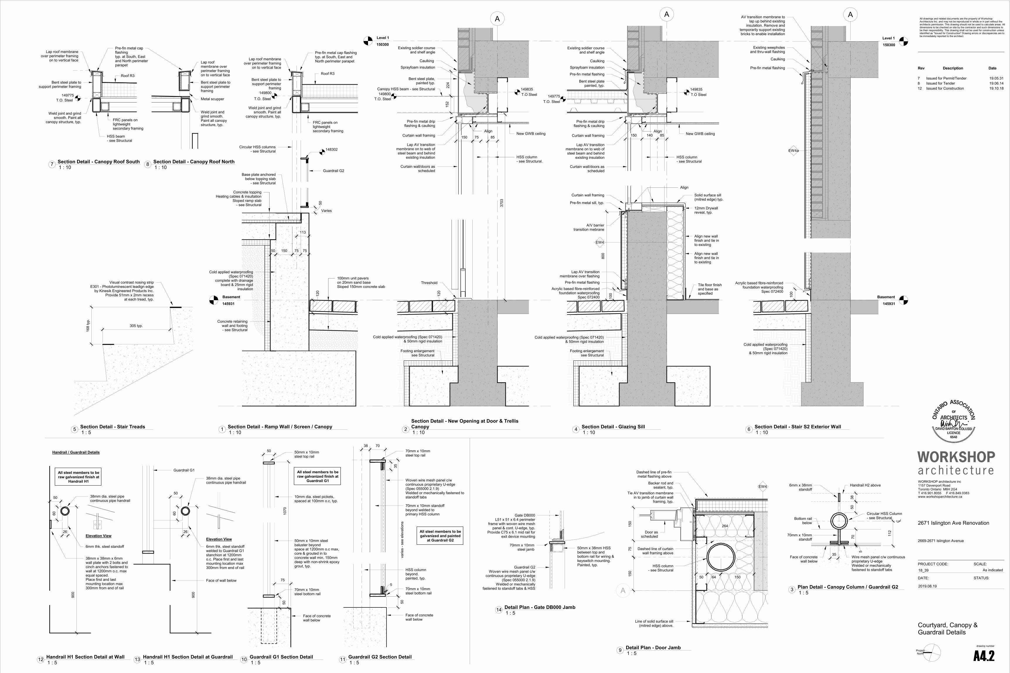
Basement
145931
149800
75 75
148302Circular HSS columns - see Structural
100mm unit paverson 20mm sand baseSloped 150mm concrete slab
120
Concrete retaining wall and footing- see Structural
Concrete toppingHeating cables & insultation
Sloped ramp slab- see Structural
150
Cold applied waterproofing (Spec 071420)
complete with drainage board & 25mm rigid
insulation
T.O. Steel
Base plate anchored below topping slab
- see Structural
Guardrail G2
Bent steel plate to support perimeter
framing
Lap roof membrane over perimeter framing
on to vertical face
Pre-fin metal cap flashingtyp. at South, East and North perimeter parapet
FRC panels on lightweight secondary framing
Weld joint and grind smooth. Paint all
canopy structure, typ.
Roof R3
50
50
Varies
113
Level 1
150300
A
Existing soldier course and shelf angle
HSS column - see Structural.
T.O Steel
Cold applied waterproofing (Spec 071420)& 50mm rigid insulation
Curtain wall/doors as scheduled
Sprayfoam insulation
Pre-fin metal drip flashing & caulking
Lap AV transition membrane on to web of steel beam and behind
existing insulation
149800T.O. Steel
Curtain wall framing
3703
224
85
152
Caulking
149835
Bent steel plate, painted typ.
150
Threshold
Canopy HSS beam - see Structural
120
New GWB ceilingAlign75
Footing enlargementsee Structural
7050
5
Handrail H2 above
70mm x 10mm standoff
Wire mesh panel c/w continuous proprietary U-edgeWelded or mechanically fastened to standoff tabs
Face of concrete wall below
Circular HSS Column- see StructuralBottom rail
below
112
6mm x 38mm standoff
38
35
A
Pre-fin metal sill, typ.
A/V barrier transition mebrane
Curtain wall framing
Existing soldier course and shelf angle
HSS column - see Structural
Sprayfoam insulation
T.O. Steel
Align
800
85
T.O Steel
Curtain wall/doors as scheduled
Pre-fin metal drip flashing & caulking
Lap AV transition membrane on to web of steel beam and behind
existing insulation
Curtain wall framing
Caulking
149835
Bent steel platepainted, typ.
150 140
149775
Solid surface sill (mitred edge) typ.
12mm Drywall reveal, typ.
Cold applied waterproofing (Spec 071420)& 50mm rigid insulation
Align new wall finish and tie in to existing
Align new wall finish and tie in to existing
Tile floor finish and base as specified
EW4
Pre-fin metal flashing
New GWB ceilingAlign
Pre-fin metal flashing
Lap AV transition membrane over flashing
100
Footing enlargementsee Structural
Acrylic based fibre-reinforced foundation waterproofing
Spec 072400
168
typ.
305 typ.
Visual contrast nosing stripE301 - Photoluminescent leadign edge
by Kinesik Engineered Products Inc.Provide 51mm x 2mm recess
at each tread, typ.
Level 1
150300
Basement
145931
A
Existing weepholes and thru-wall flashing
100
Cold applied waterproofing (Spec 071420)
& 50mm rigid insulation
EW4a
Pre-fin metal flashing
Caulking
AV transition membrane to lap up behind existing
insulation. Remove and temporarily support existing bricks to enable installation
Acrylic based fibre-reinforced foundation waterproofing
Spec 072400
HSS beam- see Structural
Bent steel plate to support perimeter framing
Lap roof membrane over perimeter framing
on to vertical face
Pre-fin metal cap flashingtyp. at South, East and North perimeter parapet
FRC panels on lightweight secondary framing
Weld joint and grind smooth. Paint all
canopy structure, typ.
Roof R3
T.O. Steel149775
Bent steel plate to support perimeter framing
Lap roof membrane over perimeter framing on to vertical face
.
Weld joint and grind smooth. Paint all canopy structure, typ.
Metal scupper
A
Line of solid surface sill (mitred edge) above.
HSS column- see Structural
Dashed line of curtain wall framing above
Door as scheduled
Dashed line of pre-fin metal flashing above
EW4
Tie AV transition membrane in to jamb of curtain wall
framing, typ.
Backer rod and sealant, typ.
150
7515
0
50 150
264
64
70mm x 10mm standoff beyond welded to primary HSS column
Woven wire mesh panel c/w continuous proprietary U-edge (Spec 055000 2.1.9)Welded or mechanically fastened to standoff tabs
70mm x 10mm steel top rail
35
50
70mm x 10mm steel bottom rail
varie
s - s
ee e
leva
tions
HSS column beyond.painted, typ.
Face of concrete wall below
5
38 70
All steel members to be galvanized and painted
at Guardrail G250mm x 10mm steel baluster beyondspace at 1200mm o.c max, core & grouted in to concrete wall min. 150mm deep with non-shrink epoxy grout, typ.
10mm dia. steel pickets,spaced at 100mm o.c, typ.
50mm x 10mm steel top rail
50
70mm x 10mm steel bottom rail
1070
Face of concrete wall below
75
50
All steel members to be raw galvanized finish at
Guardrail G1
All steel members to be raw galvanized finish at
Handrail H1
900
38mm x 38mm x 6mm wall plate with 2 bolts and cinch anchors fastened to wall at 1200mm o.c. maxequal spaced.Place first and last mounting location max 300mm from end of rail
38mm dia. steel pipe continuous pipe handrail
60
Elevation View26
6mm thk. steel standoff
50
900
38mm dia. steel pipe continuous pipe handrail
60
Elevation View
26
6mm thk. steel standoff welded to Guardrail G1 stanchion at 1200mm o.c. Place first and last mounting location max 300mm from end of rail
50
Face of wall below
Guardrail G1
70mm x 10mm steel jamb
Guardrail G2Woven wire mesh panel c/w
continuous proprietary U-edge (Spec 055000 2.1.9)
Welded or mechanically fastened to standoff tabs & HSS
50mm x 38mm HSS between top and bottom rail for wiring & keyswitch mounting.Painted, typ.
Gate DB000L51 x 51 x 6.4 perimeter
frame with woven wire mesh panel & cont. U-edge, typ.
Provide C75 x 6.1 mid rail for exit device mounting
ProjectNorth
PROJECT CODE: SCALE:
WORKSHOP architecture inc1157 Davenport RoadToronto Ontario M6H 2G4T 416.901.8055 F 416.849.0383www.workshoparchitecture.ca
All drawings and related documents are the property of Workshop Architecture Inc. and may not be reproduced in whole or in part without the architects permission. This drawing should not be used to calculate areas. All dimensions to be checked on site by the contractor and such dimensions to be their responsibility. This drawing shall not be used for construction unless identified as "Issued for Construction" Drawing errors or discrepancies are to be immediately reported to the architect.
drawing number
DATE: STATUS:
As indicated18_39
A4.2
2671 Islington Ave Renovation
2669-2671 Islington Avenue
Courtyard, Canopy &Guardrail Details
2019.08.19
1 : 101 Section Detail - Ramp Wall / Screen / Canopy1 : 102Section Detail - New Opening at Door & TrellisCanopy
1 : 53 Plan Detail - Canopy Column / Guardrail G2
1 : 104 Section Detail - Glazing Sill1 : 55 Section Detail - Stair Treads
1 : 106 Section Detail - Stair S2 Exterior Wall
1 : 107 Section Detail - Canopy Roof South1 : 108 Section Detail - Canopy Roof North
1 : 59 Detail Plan - Door Jamb
1 : 511 Guardrail G2 Section Detail1 : 510 Guardrail G1 Section Detail
Handrail / Guardrail Details
1 : 512 Handrail H1 Section Detail at Wall1 : 513 Handrail H1 Section Detail at Guardrail
1 : 514 Detail Plan - Gate DB000 Jamb
Rev Description Date
7 Issued for Permit/Tender 19.05.318 Issued for Tender 19.06.1412 Issued for Construction 19.10.18

Roof - Lower
161527
200m
m m
in.
Pre-fin alum cap flashing on sloped
plywood framing
Lap A/V transition barrier from face of
framing over parapet min 150mm
Roof membrane base sheet to carry up over parapet framing
100
R1
Existing wall assembly to remain
Existing soffit and gutter to remain
Existing roof to remain
Existing roof slab to remain
Cant. strip
Notch cap flashing around post beneath existing metal plate. Caulk around plate perimeter
Existing roof support fins, plates and posts to remain
Ex. High Parapet
162060
Ex. Low Parapet
161730
1' -
1"0'
- 8"
Roof - Lower
161527
Ex. High Parapet
162060
Pre-fin alum cap flashing on sloped
plywood framing
Lap A/V transition barrier to lap over concrete upstand
Roof membrane base sheet to carry up over parapet framing and on to vertical face
100
R1
Existing wall assembly to remain
Existing soffit and gutter to remain
Existing roof to remain
Existing roof slab to remain
Notch cap flashing around post beneath existing metal plate. Caulk around plate perimeter
Existing roof support fins, plates and posts to remain
200m
m m
i n.
Roof - Lower
161527
Pre-fin metal flashing
R1
Existing wall assembly to remain
Cut back existing corrugated metal
cladding to suit new roof and reglet flashing.Add new base trim
200m
m m
in.
Pre-fin metal cap flashing
Lap A/V transition barrier over parapet on to vertical face of framing
Cut back existing roof membrane to interior face of parapet. Lap and
seal new roof membrane over parapet framing and on to existing
164957New Parapet /
Insulation High Pt
R2
Flute closure and seal
Program Room Roof
163864
Pre-fin alum cap flashing on sloped
plywood framing
Lap A/V transition barrier to lap over concrete upstand
Roof membrane base sheet to carry up over parapet framing and on to vertical face
100
R1
1524
site
ver
ify
Roof membrane cap sheet lapped on to continuous
pre-fin metal flashing
Lap A/V transition barrier over parapet on to
vertical face of framing
164957New Parapet /
Insulation High Pt 100
Existing corrugated metal cladding
Add new corrugated metal cladding to
match existing
R2
Program Room Roof
163864
Reglet flashingheight/depth to match parapet cap flashing beyond
R1
Level 1
150300
Level 2
154669
A
North East Grade
147700
10A4.3
11A4.3
1:6Roof R4
EW2
Locally remove and reinstate brick veneer to suit new wall plates
- see Structural
Roof R4Z-stiffners as req'd (provide
butyl tape under z-bar)
J-channel support
Gutter
Gutter clips
Lap A/V transition membrane on to J-
channel. Provide weep holes
1:625
EW2
220
Lap AV transition membrane on to thru-wall pre-fin
metal flashingLintel beam- see Structural
200m
m m
in.
Roof R4
Pre-fin metal flashingReturn flashing at North and South
sides - caulk joint at brick
Tuck flashing behind existing sill flashing and caulk. Provide reglet ea.
side of window to match sill height
HSS Support -see Structural
Roof - Lower
161527
Roof drain
Lap cap sheet over drain flange and reinforcement membrane as per manufacturers detail
Existing roof drain slab penetration
R1
Level 1
150300
1
North East Grade
147700
Connect gutter in to existing RWL
EW2EW2
9A4.3
North East Grade
147700
200
600
Thru-wall membrane flashing at top of foundation/curb wall, typ.
Pre-finsihed metal sill flashing over sloped pressue treated wood blocking
EW2
Lap A/V transition membrane over flashing
Floor F1
350
Roof - Lower
161527
Existing HSS column to remain
200
Sealant, typ.
Pre-fin metal flashing
Cap sheet
Base sheetR1
PROJECT CODE: SCALE:
WORKSHOP architecture inc1157 Davenport RoadToronto Ontario M6H 2G4T 416.901.8055 F 416.849.0383www.workshoparchitecture.ca
All drawings and related documents are the property of Workshop Architecture Inc. and may not be reproduced in whole or in part without the architects permission. This drawing should not be used to calculate areas. All dimensions to be checked on site by the contractor and such dimensions to be their responsibility. This drawing shall not be used for construction unless identified as "Issued for Construction" Drawing errors or discrepancies are to be immediately reported to the architect.
drawing number
DATE: STATUS:
As indicated18_39
A4.3
2671 Islington Ave Renovation
2669-2671 Islington Avenue
Waste Storage & RoofingDetails
2019.08.19
1 : 103 Section Detail - Lower Roof Low Parapet1 : 104 Section Detail - Lower Roof High Parapet
1 : 105 Section Detail - Lower Roof Gable
1 : 106 Section Detail - Upper Roof Parapet1 : 101 Section Detail - Program Room Roof Flashing
1 : 107 Section Detail - Upper Roof Gable1 : 108 Section Detail - Program Room Roof Reglet
1 : 502 Section Thru Waste Storage - South1 : 1010 Section Detail - Waste Storage Door & Gutter
1 : 1011 Section Detail - Waste Storage Roof at Exterior Wall
1 : 1012 Section Detail - Roof Drain
1 : 5013 Section Thru Waste Storage - West1 : 109 Section Thru Waste Storage - Typical Wall
1 : 1014 Section Detail - Existing Column
Rev Description Date
6 Issued for 75% Costing 19.04.117 Issued for Permit/Tender 19.05.318 Issued for Tender 19.06.1412 Issued for Construction 19.10.18