a wireless sensor network for greenhouse climate...
TRANSCRIPT

Published by the IEEE CS n 1536-1268/13/$31.00 © 2013 IEEE PERVASIVE computing 49
T r a c k i n g a n d S e n S i n g i n T h e W i l d
a Wireless Sensor network for greenhouse climate control
W ireless sensor networks are an important pervasive com-puting technology invad-ing our environment. Over the years, research into
WSN technology has matured to the extent that the ZigBee, based on IEEE 802.15.4, has emerged as a communication and networking standard to cater to the unique needs of WSN. It’s a low-power (a few µW), low-data-rate (250
kbps), fault-tolerant, easily scalable, short-range (100 m) wireless protocol for embed-ded electronic devices called sensor nodes.1 ZigBee and ZigBee-like standard-based WSN products and systems are now available to suit a vari-ety of applications, including environment monitoring, pre-cision agriculture, home and
building automation, healthcare, traffic man-agement, and so on.2–4 WSNs are also gaining importance in controlled environmental agri-culture technology, especially in greenhouse horticulture, because they offer wireless and flexible installation and reliable operation. (See the “Related WSN Work in Greenhouse Horti-culture” sidebar for more information.)
Motivated by the idea of integrating a WSN into a high-level programming language to
develop a custom application of public inter-est, we developed and field-tested a novel sys-tem for greenhouse climate control. Our system provides microclimate monitoring of the green-house temperature and relative humidity and analyzes the greenhouse crops’ vapor pressure deficit (VPD), an important climate parameter related to plant growth, health, and yield condi-tions. To enhance the monitoring network, we integrated into it a VPD-based MIMO (multi-ple input and multiple output) fuzzy climate controller and an RS-485 actuator network to automate the greenhouse climate-control op-erations. Here, we discuss the technical issues we faced in designing this greenhouse-specific WSN and in implementing its intelligent appli-cation software.
Material and MethodsFirst, we had to gather greenhouse domain knowledge to gain a better understanding of greenhouse crops, work activities, operations, and research trends.1,2
In particular, we needed to understand the microenvironment. A greenhouse is a complex, multivariable interactive system. Because of lo-cal weather fluctuations, the plant-growing pro-cess and its interaction with internal climatic conditions, and the use of different climate con-trol equipment, the greenhouse environment is highly dynamic and varies spatially, thus creating
Using a wireless sensor network, the authors developed an online microclimate monitoring and control system for greenhouses. They field-tested the system in a greenhouse in Punjab, India, evaluating its measurement capabilities and network performance in real time.
Roop PahujaNational Institute of Technology Jalandhar
H.K. VermaSharda University, India
Moin UddinDelhi Technological University
PC-12-02-Pah.indd 49 3/23/13 11:13 AM
50 PERVASIVE computing www.computer.org/pervasive
Tracking and SenSing in The Wild
microclimate zones. Climatic condi-tions vary from the greenhouse center to its side walls, and from the canopy to the aerial levels.5
We also needed to automate various operations and decisions. We had to gather and analyze plant-related sen-sory data using proactive computing methodology2 to obtain the actionable output decisions for the different plant-related operations driving the in-house actuating equipment (operations such as climate control, fertigation control, irrigation control, and integrated pest management).
Finally, we needed to provide online information. Sophisticated software must provide online connectivity to the greenhouse control system with GUIs to display microclimate data sta-tistics, decision support, and control operations.6
The need for greenhouse micro-environment monitoring to get reliable climate measurements, with better
spatial and temporal resolution, has caused a paradigm shift from single-point fixed sensing to multipoint, multi-variable flexible sensing. This has given WSNs an edge over wired networks. Moreover, to help automate green-house operations, a WSN can be inte-grated with an actuator network and a high-level programming platform to implement an online information sys-tem that growers can easily access.
To address these issues, we imple-mented the WSN-based online micro-climate monitoring and control system shown in Figure 1.
The Wireless Sensor networkOur greenhouse WSN is a deterministic network based on IEEE 802.15.4 and XMesh.7 Like ZigBee, it’s a robust, full-featured multihop, ad-hoc, mesh net-working protocol for embedded sensor devices for Crossbow motes. Network hardware comprises numerous battery-operated sensor nodes with embedded
temperature and relative humidity sen-sors and a gateway node.8,9 Each node is preprogrammed in TinyOS,10 the component-based, event-driven embed-ded operating system that defines each node’s sensing, computation, commu-nication, and routing capabilities. To design a versatile, flexible, and robust WSN for greenhouse custom applica-tions, we had to address the following technical issues.
Climate-control variables. The impor-tant climate-control variables we con-sidered to evaluate the greenhouse-crop VDP were the temperature (ranging from –10 to 50° C) and relative humid-ity (from 0 to 100 percent) within the greenhouse canopy and aerial height levels. The crop VPD is defined as the difference between the saturated vapor pressure at the canopy level at a given temperature and the actual vapor pres-sure present in the air at that temperature and relative humidity. Saturated vapor
C arlos Serodio and his colleagues—part of a multi-
disciplinary research group in Portugal—designed and
implemented a networked platform using a wireless sensor
network (WSN), controller area network (CAN), and Internet
and email tools. Their platform offers computerized agriculture
management systems in a greenhouse to support distributed
data acquisition and control, helping growers make better deci-
sions in carrying out agricultural practices in a greenhouse.1
Zhou Yiming and his colleagues discussed the hardware and
software design of a ZigBee WSN node with temperature, rela-
tive humidity, and moisture sensors and proposed a star or mesh
network architecture for a greenhouse WSN system.2 Hui Liu
and his colleagues designed the Crossbow WSN for measuring
temperature, light intensity, and soil moisture using a terminal
interface for logging and displaying data, along with experimen-
tal testing of antenna heights that effect radio range.3
Teemu Ahonen and colleagues developed a node using the
Sensinode sensor platform fitted with temperature, relative-
humidity, and light-intensity sensors based on the 6LoWPAN
protocol. They tested its feasibility by deploying a simple sensor
network into a greenhouse in Western Finland.4 One-day experi-
ment data was collected to evaluate the network reliability and
its ability to detect the microclimate layers.
Dae Heon Park and his colleagues developed a WSN-based
greenhouse environmental monitoring and dew point control
system that prevents dew condensation phenomena on the
crop’s surface, helping to prevent diseases and infections.5
REfEREnCES
1. C. Serodio et al., “A Network Platform for Agriculture Management System,” Computer and Electronics in Agriculture, vol. 31, no.1, 2001, pp. 75–90.
2. Z. Yiming et al., “A Design of Greenhouse Monitoring and Control System Based on ZigBee WSN,” Proc. Int’l Conf. Wireless Comm. Net-working and Mobile Computing, WiCOM, 2007, pp. 2563–2567.
3. H. Liu, Z. Meng, and S. Cui, “A Wireless Sensor Network Prototype for Environmental Monitoring in Greenhouse,” Proc. Int’l Conf. Wireless Comm. Networking and Mobile Computing, WiCOM, 2007, pp. 2344–2347.
4. T. Abhonen, R. Virrankoski, and M. Elmusrati, “Greenhouse Moni-toring with Wireless Sensor Network,” Proc. IEEE/ASME Int’l Conf.: Mechtronics and Embedded Systems and Applications, MESA, 2008, pp. 403–408.
5. D. Heon Park and J.-W. Park, “Wireless Sensor Network-Based Green-house Environment Monitoring and Automatic Control System for Dew Condensation Prevention,” Sensors (Basel), vol. 11, no. 4, 2011, pp. 3640–3651.
related WSn Work in greenhouse horticulture
PC-12-02-Pah.indd 50 3/23/13 11:13 AM
APRIL–JuNE 2013 PERVASIVE computing 51
pressure is a function of temperature and is calculated using the Arrhenius equation.11
The effect of having different temper-atures at the canopy and aerial levels and relative humidity in a greenhouse is quantized as the greenhouse-crop VPD, which controls the transpiration rate and thus plant growth, health, and yield.12 These climate variables fluc-tuate slowly and spatially within the greenhouse. A reporting-time interval of 15 minutes or so is recommended to extract dynamic statistics.6
Network deployment scheme. The greenhouse WSN comprises a few sensor nodes deployed inside the green-house at specific locations and a sin-gle node deployed outside to sense weather parameters. A gateway node is connected to the server in the control room to facilitate data communication.
To calculate the crop VPD and mea-sure spatial variability of parameters within the greenhouse, we used a grid- and height-based deterministic, site- specific, and uniform deployment scheme (see Figure 1).
In this scheme, the greenhouse floor area is virtually partitioned into grids of uniform size, with two height levels— one within the canopy and the other at aerial levels (1.5 m above the canopy). Each location has an ID label, gihj, where i denotes the grid number (1 to n, where n is the maximum number of grids in the greenhouse), and j denotes the height number (1, 2). We placed at least one sensor node (preprogrammed with a relative location node ID) at each grid and height zone to measure the temperature and relative humidity. The grid size (200 to 500 m2) charac-terizes the spatial variation of these parameters, keeping in mind that nodes
are within radio range of each other (50 m).8 There’s a trade-off between the grid size, number of nodes (cost), and spatial resolution.
Node addressing scheme. We used an addressing scheme based on the rela-tive location of the node (RLN) for lo-cation identification. The RLN ID tags have a four-digit number represented as GHNN, where G denotes the grid number (1 to 9), H (1, 2) denotes the height number, and NN (00–99) de-notes the node ID (which uniquely iden-tifies the node in the greenhouse). This scheme allows site-specific deployment of nodes at the identified locations in the greenhouse.
Based on this ID tag, we used loca-tion mapping to extract data from each node location at the server. In addition to providing location-aware sensing of greenhouse parameters, this mapping
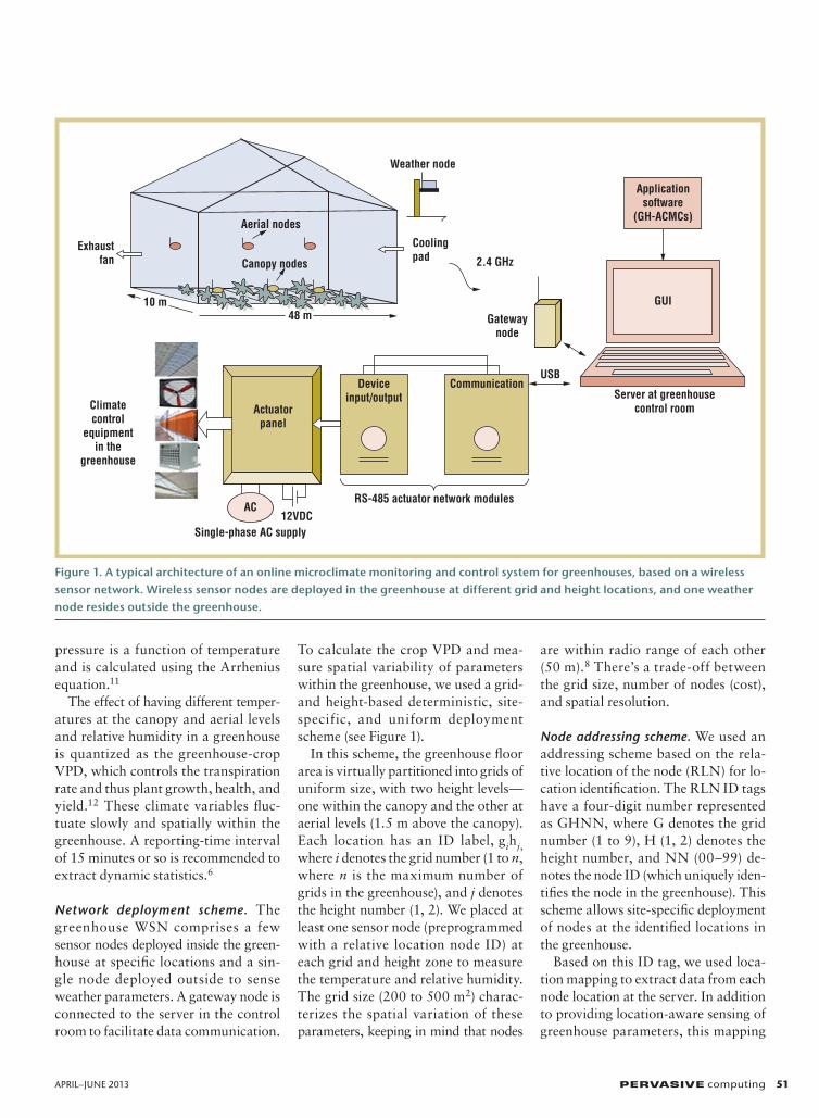
Figure 1. A typical architecture of an online microclimate monitoring and control system for greenhouses, based on a wireless sensor network. Wireless sensor nodes are deployed in the greenhouse at different grid and height locations, and one weather node resides outside the greenhouse.
Climatecontrol
equipmentin the
greenhouse
Aerial nodes
Canopy nodesExhaust
fan
10 m
Actuatorpanel
48 m
Deviceinput/output
Communication
RS-485 actuator network modules12VDC
Single-phase AC supply
Weather node
Coolingpad 2.4 GHz
Gatewaynode
USB
Server at greenhousecontrol room
GUI
Applicationsoftware
(GH-ACMCs)
AC
PC-12-02-Pah.indd 51 3/23/13 11:13 AM

52 PERVASIVE computing www.computer.org/pervasive
Tracking and SenSing in The Wild
was more power efficient, simple, and straightforward to implement than a GPS-enabled, dynamic location-aware sensing scheme.1
Data acquisition and transmission. To continuously monitor the greenhouse signal dynamics for better precision control, we used a periodic sampling with averaged delayed transmission (PSDT) data-acquisition and transmis-sion algorithm. Instead of periodically sampling the sensor signals and trans-mitting the acquired data at the same instant, the PSDT algorithm lets the node periodically sample the sensor signals at a faster sampling rate, collect a few samples, and periodically trans-mit the averaged sampled values at a higher transmission than sampling rate. Both temperature and relative humid-ity are sampled at two-minute time in-tervals, and the latest averaged sampled values of each within a 15-minute time frame are packetized and transmitted to the gateway node.
This technique improves the reliabil-ity with which signals are sampled and is power efficient. It supports high la-tency operation and averaging to com-press data samples without sacrificing measurement accuracy and data integ-rity. The transmission rate is fixed and is appropriate for any crop.
Network topology and routing. Thick plantation and canopy coverage in a greenhouse can diminish the signal range of nodes forming the network, so packet losses can occur. To have a reliable and scalable network under such situations, a true mesh multihop network topology is preferred over a star- or hybrid-cluster-based topology.
All greenhouse nodes are full func-tional devices with both sensing and routing capabilities and one coordi-nator (gateway) node. Based on the XMesh routing algorithm, each node transmits its data packet to the coor-dinator node via the other parent node using multihops and the most efficient energy path. The node periodically
updates its routing information (every six minutes) and dynamically creates new routes. As soon as a new node is added, it joins the network and starts transmitting data. The node remains in a low-power mode (with the transmit-ter in sleep mode and the receiver in a low-power listening mode) when there’s no data or other message to receive or transmit.7
This topology extends the radio range of the devices with low-power consumption (a few mA), providing a field life of more than a month on a pair of AA standard cells (3 volts). Further-more, it provides better coverage with self-healing and self-configuration ca-pabilities, forming a fault-tolerant net-work well-suited for greenhouses.
The actuator networkTo automate the greenhouse climate-control process, we used an actuator network from Advantech, based on the RS-485 industrial serial-networking standard. We connected greenhouse end devices (single-phase 220-volt AC motors, pumps, and starters) associ-ated with climate-control equipment to the network module’s relay ports (12 V DC 220 ohm). In response to the climate controller output, which de-cides the operating load and presents the status of climate-control equip-ment, the actuator network drive-layer program issues commands to RS-485 network devices to actuate particular relays, controlling the equipment by varying the load.
application SoftwareWe programmed the application software—the greenhouse advance microclimate monitoring and control software (GH-ACMCs)—for discrete packet acquisition and time-series analysis of network multivariate data. The GH-ACMCs lets us execute micro-climate monitoring, climate control, and decision support functions, and it updates all vital greenhouse informa-tion on the GUI. Figure 2 shows the software’s functional design model.
Packet acquisition, scanning, and deciphering. Packet acquisition is fun-damental in providing connectiv-ity to the greenhouse WSN. Using a point-by-point packet-acquisition and -collection method, network data packets interfacing with a PC port at the gateway node at any instant of time t are acquired and logged with a timestamp. Based on a variable timeframe-scanning algorithm, the logged data packets are scanned within the latest timeframe window tw (with a typical value of 20 minutes). The time-frame window denotes the time during which the latest data from the node is available—in other words, during this timeframe, the node has (at least once) communicated its data to the central server system. The scanning starts with the current time. Then, by decrement-ing the time by one minute until the timeframe limit is met, the algorithm collects the packets transmitted from nodes within this timeframe.
From the scanned packets, each node ID is location mapped to sepa-rate the node packets for different locations. Corresponding to each lo-cation node ID, the latest packet avail-able in the timeframe window is con-sidered as the node packet from that location at that time instant. The raw data packets are deciphered and 16-bit digital data for node voltage, tem-perature, and humidity are converted to corresponding values in engineer-ing units using sensor conversions.13 An amplitude rejection-fi ltering technique filters out data packets that are undesirable due to a sensor mal-functioning. This method synchro-nizes the display of data from each node in the timeframe at each time in-stant and updates the information on the GUI as soon as a new packet from any node is detected. Without this method, it’s difficult to coordinate all nodes and provide stable, reliable, and timely network information from an asynchronous, high-latency (15 min-utes) network with an intermediate low-power mode of operation.
PC-12-02-Pah.indd 52 3/23/13 11:13 AM
APRIL–JuNE 2013 PERVASIVE computing 53
Collaborative data processing and micro-climate monitoring. The preprocessed time-instant values of temperature and relative humidity, as measured by nodes at different locations, are collaboratively processed to evalu-ate the crop VPD at each grid and provide reliable average values of cli-mate variables.11,12 Data from differ-ent nodes is statistically analyzed to
project the spatial variation of climatic variables in the grids and at various height levels (3D plots). The spatial variability (standard deviation) value for each climate variable is calculated to estimate the data spread. VPD- histogram and cumulative frequency-distribution graphs are obtained to an-alyze the frequency of VPD variation in different ranges and the amount of
time during which the VPD is less than a certain value.
Climate control. To regulate the green-house climatic conditions automati-cally, we implemented a VPD-based fuzzy climate controller,14,15 operat-ing under a feed-forward mode us-ing a variable-load design method. With respect to the variations in the
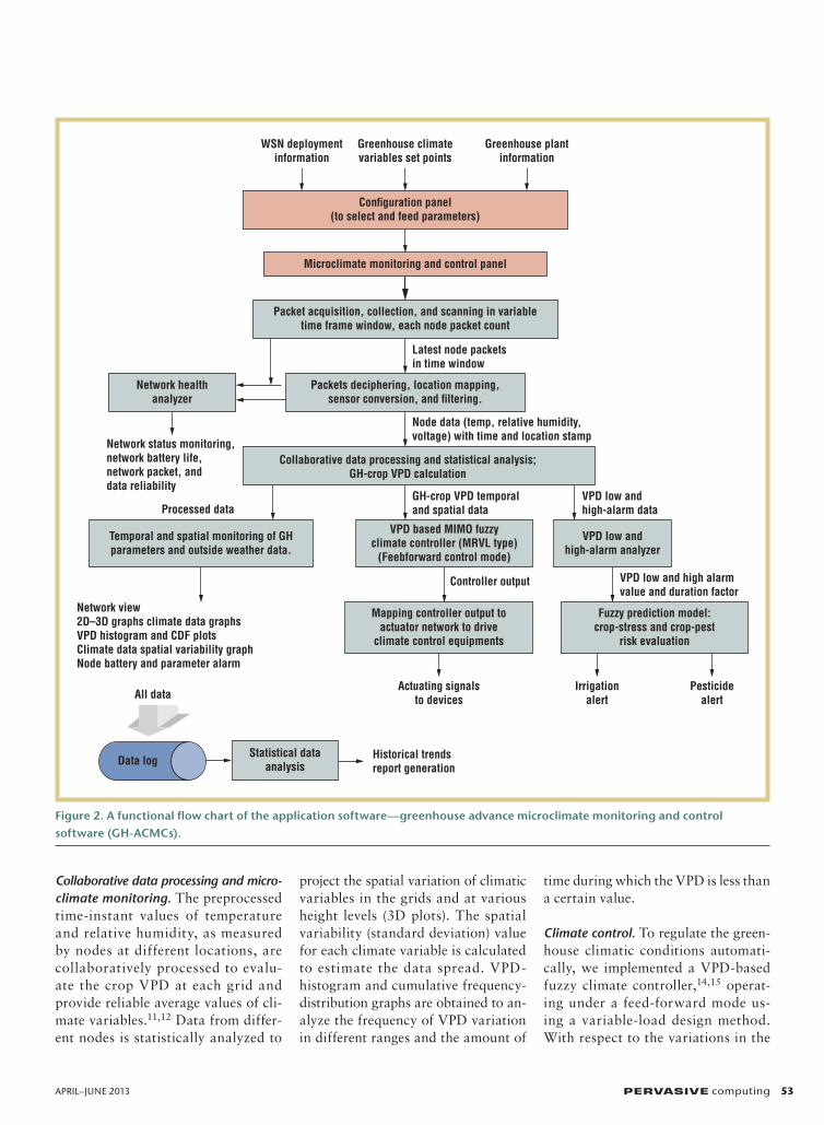
Figure 2. A functional flow chart of the application software—greenhouse advance microclimate monitoring and control software (GH-ACMCs).
WSN deploymentinformation
Greenhouse climatevariables set points
Greenhouse plantinformation
Con�guration panel(to select and feed parameters)
Microclimate monitoring and control panel
Packet acquisition, collection, and scanning in variabletime frame window, each node packet count
Latest node packetsin time window
Packets deciphering, location mapping,sensor conversion, and �ltering.
Node data (temp, relative humidity,voltage) with time and location stamp
Network status monitoring,network battery life,network packet, anddata reliability
Network healthanalyzer
Collaborative data processing and statistical analysis;GH-crop VPD calculation
GH-crop VPD temporaland spatial data
VPD low andhigh-alarm data
VPD low andhigh-alarm analyzer
Processed data
Temporal and spatial monitoring of GHparameters and outside weather data.
VPD based MIMO fuzzyclimate controller (MRVL type)
(Feebforward control mode)
VPD low and high alarmvalue and duration factor
Controller output
Mapping controller output toactuator network to drive
climate control equipments
Fuzzy prediction model:crop-stress and crop-pest
risk evaluation
Network view2D–3D graphs climate data graphsVPD histogram and CDF plotsClimate data spatial variability graphNode battery and parameter alarm
All data
Statistical dataanalysis
Historical trendsreport generation
Actuating signalsto devices
Irrigationalert
Pesticidealert
Data log
PC-12-02-Pah.indd 53 3/23/13 11:13 AM
54 PERVASIVE computing www.computer.org/pervasive
Tracking and SenSing in The Wild
outside-weather VPD, we calculated the VPD error and its rate of change. Cor-responding to each error range (positive and negative) are different rule-based fuzzy controllers that issue signals to drive different climate-control equip-ment and regulate inside conditions. Controller inputs, the VPD error, and the VDP error’s rate of change are nor-malized into seven linguistic terms, and 49 control rules for each actuating sys-tem (roof vents, exhaust fan, cooling pad, and heaters) are designed, taking into account how varying the operating load of each affects the inside climatic condition.
When the VPD error is positive, the greenhouse is humidified by control-ling the operating load of ventilation and cooling equipment. When the VPD error is negative, the greenhouse is de-humidified by controlling the operating load of ventilation and heating equip-ment. We operate a shade screen to in-crease the efficiency of the cooling and heating system in extreme summer and winter conditions. When the outside temperature exceeds 35ºC during the day and falls below 5ºC at night, the shade screen is covered. The RS-485 actuator network driver-layer program maps the controller output to issue com-mands to drive the devices. Based on the user-specified temperature and relative
humidity limits, suited for the crop dur-ing its growing phase, VPD set limits are calculated to drive controller inputs.
Crop-stress and -disease risk prediction. The quantitative analysis of alarming VPD conditions helps predict VPD’s harmful effect on crops—that is, when the crop is under stress due to continu-ous high VPD conditions (high tem-perature and low humidity), or when there are chances of disease outbreak due to continuously low VPD (low tem-perature and high humidity), which can cause condensation on leaves. This functional module uses heuristic rule-based fuzzy controllers and a cumula-tive moving-average method to analyze VPD high and low alarm conditions (in terms of the grid and area), based on the VPD’s alarm duration (during the normal irrigation and pesticide sched-ule) and the extent of the high and low VDP values to estimate a crop-stress and crop-disease risk index (0 to 1). Af-ter comparing these two indices to the threshold limit, irrigation and pesticide warning messages are issued for each grid and greenhouse area.12,16
Network performance monitoring. This functional module evaluates some of the important parameters related to a WSN’s field performance in a greenhouse.1
It tracks the number of nodes con-nected at each timeframe limit and displays the network connectivity sta-tus (“okay,” “network initializing,” or “detection or connection problem”). It has a low-battery alarm (2.3 V) and in-dicates the network mean-battery life and network mean packet reliability (as percentages). It also tracks data con-nectivity based on the display of vital information—the average crop VPD or outside VPD—and calculates network data reliability (as a percentage).
Implementation. All of the functional elements of the GH-ACMCs are imple-mented on the graphical dataflow pro-gramming platform, LabVIEW (8.5), from National Instruments.17 It’s a multi panel, modular, hierarchically designed software tool with an intuitive GUI that supports different levels of functionalities with intelligent, salient features. The configuration panel lets the user feed and select user-defined parameters related to greenhouse net-work deployment and plant-specific requirements, such as the temperature and relative humidity (see Figure 3). Based on these inputs, the micro-climate monitoring and control pro-gram executes all the functional mod-ules to perform online monitoring, control operations, and display vital information (see Figure 4).
Field resultsTo test the system’s feasibility and judge its measurement and network performance in a real-world field situation, we de-ployed it in a commercial chili-growing glasshouse, situated in a tropical region of northern India in the state of Pun-jab, near the city of Ludhiana. Green-house cultivation is a daunting task for the region’s local growers during the summer season (May through August), when the outside VPD exceeds 70 mil-libars (mB) owing to high temperatures (above 40°C) and moderate relative humidity (20 to 60 percent). To evalu-ate the greenhouse climate dynamics and statistics under this harsh summer
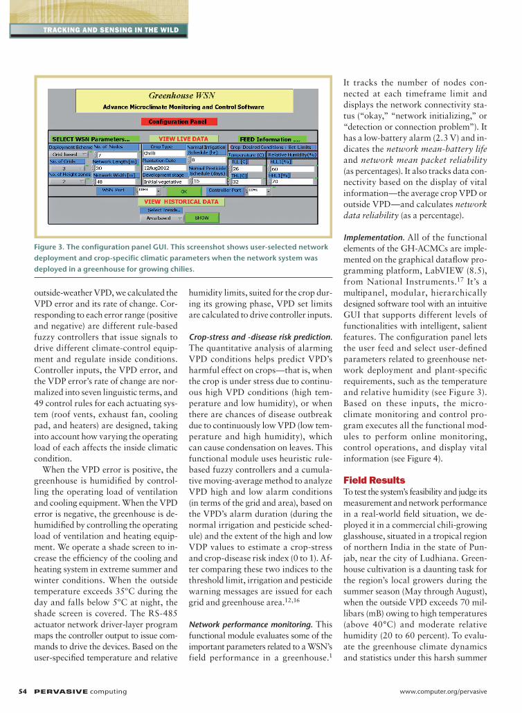
Figure 3. The configuration panel GUI. This screenshot shows user-selected network deployment and crop-specific climatic parameters when the network system was deployed in a greenhouse for growing chilies.
PC-12-02-Pah.indd 54 3/23/13 11:13 AM
APRIL–JuNE 2013 PERVASIVE computing 55
weather, we conducted a short-term ex-periment during the peak day hours.
Preprogrammed wireless sensor nodes packed in PVC housings, equipped with a standard pair of AA cell batteries (3.0–3.2 V), were powered “on” and deployed at specific locations in the greenhouse (using the grid-height based deployment scheme explained earlier). As shown in Figure 1, the greenhouse section area (30 × 48 m2, East to West direction) was divided into three grids—left (G1), middle (G2), and right (G3)—of size 30 × 16 m2, and at the center of each grid, one node was placed in the canopy (the aver-age crop size was initially 12 cm) to mea-sure the canopy temperature and relative humidity. Another node was fixed at the aerial height level (1.5 m above the can-opy) to measure the aerial temperature and relative humidity. The weather node was mounted outside the greenhouse, and the gateway node was interfaced to the server housed at the greenhouse con-trol room (40 m from greenhouse site).
To automate the climate-control pro-cess, actuating device terminals were interfaced to an RS-485 actuator panel
at the greenhouse site, and an RS-485 communication module was serially connected to the host PC. Depending on the availability of the devices at the greenhouse site, the climate controller was tuned to drive the cooling pad (0, 50, and 100 percent), exhaust fan (0, 25, 50, 75, and 100 percent), shade screen (0 to 100 percent), and roof ventilation (0 to 100 percent) with variable loads.
Before starting the monitoring and control operations, we configured the GH-ACMCs. We opened the configu-ration panel to feed input parameters (Figure 3). We entered the crop com-fort zone (“set limits”) of 26° C to 32° C, with a relative humidity of 60 to 70 percent, along with the crop normal- irrigation schedule (typically eight hours) and pesticide schedule (typically 15 days), as decided by the grower during the crop development cycle (initial veg-etative growth period of chili). We also entered the network deployment infor-mation. As the configuration panel was executed, it linked the information to the microclimate monitoring and con-trol panel GUI (Figure 4).
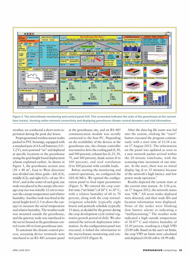
After the data-log file name was fed into the system, clicking the “start” button executed the program continu-ously with a start time of 11:34 a.m. on 17 August 2012. The information on the panel was updated as soon as a new network packet arrived within the 20-minute timeframe, with the scanning-time increment of one min-ute. At the start, there was an initial display lag (6 to 15 minutes) because of the network’s high latency and low power mode operation.7
Results depicted the system state at the current time instant. At 3:56 p.m. on 17 August 2012, the network status was “OK.” All seven nodes deployed were detected, and their node IDs and location information were displayed. None of the nodes were blinking (low battery alarm) or indicating a “malfunctioning.” The weather node indicated a high outside temperature of 38.87° C and relative humidity of 52.85 percent, resulting in a high VPD (33.89 mB). Based on the user’s set limits, the crop VPD set limits were calculated and displayed (10.06 mB to 18.99 mB).
Figure 4. The microclimate monitoring and control panel GUI. This screenshot indicates the state of the greenhouse at the current time instant, showing online network connectivity and displaying greenhouse climate-control dynamics and vital information.
PC-12-02-Pah.indd 55 3/23/13 11:13 AM
56 PERVASIVE computing www.computer.org/pervasive
Tracking and SenSing in The Wild
With respect to the current VPD error (14.9 mB), the climate control-ler output actuated the RS-485 net-work to drive the equipment with the appropriate load/operating status to humidify the greenhouse to minimize the VPD error. As indicated, the shade screen was “open” (covered), the roof vents were “closed,” and the cooling pad and exhaust fan were operating under a “full” load. The network view
graphically showed the nodes at the re-spective grid locations, indicating the local measured value of voltage, tem-perature, and relative humidity. The VPD value at each grid was calculated and displayed, along with the display of average values of the climate vari-ables at the respective indicators. The greenhouse’s average canopy tempera-ture (37.12° C) and aerial temperature (37.19° C) remained high, with moderate
aerial humidity (61.34 percent), result-ing in the high average value of crop VPD (24.72 mB). The VPD time plot indicated that because of the climate-control operation, the greenhouse VPD decreased with time and was lower than outside, but it remained higher than the set limit.
Owing to the high average VPD, the crop was under stress, and the es-timated value of the crop-stress index (area) increased 0.33 over time (after 4.36 hours) but was lower than the threshold (0.5) to initiate the irriga-tion alert alarm for the area. Also, the crop-stress risk-intensity map showed the spatial variation of the crop-stress risk index at the respective grids, based on grid VPD alarm analysis using pre-diction model and the corresponding grid irrigation alarm status. 3D plots indicated instantaneous spatial varia-tion of the microclimate variables at different grid locations, and the bar graph plotted the spatial standard de-viation of each, indicating the extent of variability of each from its average value. The greenhouse-crop grid VPD varied in the range (15.78 mB to 31.19 mB), with a spatial variability value of 7.5mB. Histogram and cumulative distribution frequency (CDF) plots indi-cated the crop VPD distribution pattern. For more than half of the time, the VPD was very high (greater than 50 mB) and then remained within 20 to 30 mB.
As indicated by the network health analyzer, the network’s mean battery life at the current time instant was highest (100 percent), because all nodes had a voltage greater than 3.0 V, with a network mean voltage drop of 0.03 V. Due to packet losses, the network mean packet reliability remained between 75 and 100 percent, but the data reliability was very high (100 percent). Data was simultaneously recorded and logged in the respective files for historical display and trend analysis.
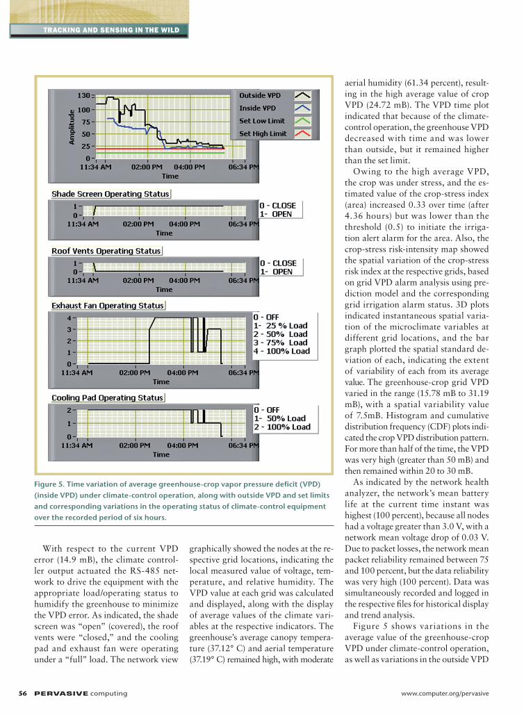
Figure 5 shows variations in the average value of the greenhouse-crop VPD under climate-control operation, as well as variations in the outside VPD
Figure 5. Time variation of average greenhouse-crop vapor pressure deficit (VPD) (inside VPD) under climate-control operation, along with outside VPD and set limits and corresponding variations in the operating status of climate-control equipment over the recorded period of six hours.
PC-12-02-Pah.indd 56 3/23/13 11:13 AM
APRIL–JuNE 2013 PERVASIVE computing 57
and set limits and the corresponding vari-ations in the actuating status and load of the climate-control equipment over the recorded period of six hours. Because the outside temperature was higher than 35°C, the shade screen was opened (cov-ered) and the roof vents remained off. Under the extreme weather conditions, during the initial hours—when the out-side VPD was extremely high (VPD error above 50 mB)—the greenhouse was humidified with the maximum cooling rate with exhaust fan ventilation turned off, resulting in a decrease of the average value of greenhouse-crop VPD, from 81.6 to 55 mB.
When the outside VPD dropped below 60 mB, the exhaust fan operating load increased from 75 percent to 100 per-cent. Increasing the ventilation rate with cooling further reduced the VPD (from 25 mB to 20 mB). When the outside VPD error dropped below 10 mB, the cooling pad and ventilation were switched to lower rates, which decreased the inside VPD to a minimum value of 18.18 mB. When the outside error was less than 1 mB and its rate of change was also negative, all the actuating devices were switched off (to the low-power mode).
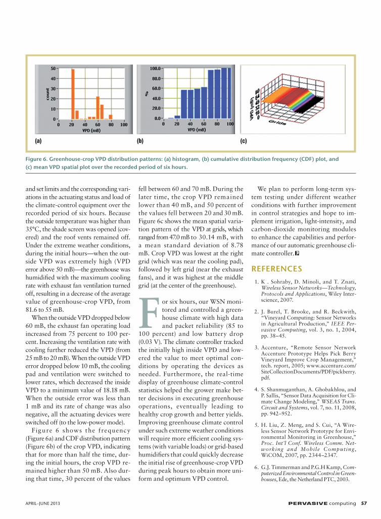
Figure 6 shows the f requency (Figure 6a) and CDF distribution pattern (Figure 6b) of the crop VPD, indicating that for more than half the time, dur-ing the initial hours, the crop VPD re-mained higher than 50 mB. Also dur-ing that time, 30 percent of the values
fell between 60 and 70 mB. During the later time, the crop VPD remained lower than 40 mB, and 50 percent of the values fell between 20 and 30 mB. Figure 6c shows the mean spatial varia-tion pattern of the VPD at grids, which ranged from 47.0 mB to 30.14 mB, with a mean standard deviation of 8.78 mB. Crop VPD was lowest at the right grid (which was near the cooling pad), followed by left grid (near the exhaust fans), and it was highest at the middle grid (at the center of the greenhouse).
F or six hours, our WSN moni-tored and controlled a green-house climate with high data and packet reliability (85 to
100 percent) and low battery drop (0.03 V). The climate controller tracked the initially high inside VPD and low-ered the value to meet optimal con-ditions by operating the devices as needed. Furthermore, the real-time display of greenhouse climate-control statistics helped the grower make bet-ter decisions in executing greenhouse operations, eventually leading to healthy crop growth and better yields. Improving greenhouse climate control under such extreme weather conditions will require more efficient cooling sys-tems (with variable loads) or grid-based humidifiers that could quickly decrease the initial rise of greenhouse-crop VPD during peak hours to obtain more uni-form and optimum VPD control.
We plan to perform long-term sys-tem testing under different weather conditions with further improvement in control strategies and hope to im-plement irrigation, light-intensity, and carbon-dioxide monitoring modules to enhance the capabilities and perfor-mance of our automatic greenhouse cli-mate controller.
ReFeRenCes 1. K . Sohraby, D. Minoli, and T. Znati,
Wireless Sensor Networks—Technology, Protocols and Applications, Wiley Inter-science, 2007.
2. J. Burel, T. Brooke, and R. Beckwith, “Vineyard Computing: Sensor Networks in Agricultural Production,” IEEE Per-vasive Computing, vol. 3, no. 1, 2004, pp. 38–45.
3. Accenture, “Remote Sensor Network Accenture Prototype Helps Pick Berry Vineyard Improve Crop Management,” tech. report, 2005; www.accenture.com/SiteCollectionDocuments/PDF/pickberry.pdf.
4. S. Shanmuganthan, A. Ghobakhlou, and P. Sallis, “Sensor Data Acquisition for Cli-mate Change Modeling,” WSEAS Trans. Circuit and Systems, vol. 7, no. 11, 2008, pp. 942–952.
5. H. Liu, Z. Meng, and S. Cui, “A Wire-less Sensor Network Prototype for Envi-ronmental Monitoring in Greenhouse,” Proc. Int’l Conf. Wireless Comm. Net-working and Mobile Computing, WiCOM, 2007, pp. 2344–2347.
6. G.J. Timmerman and P.G.H Kamp, Com-puterized Environmental Control in Green-houses, Ede, the Netherland PTC, 2003.
Figure 6. Greenhouse-crop VPD distribution patterns: (a) histogram, (b) cumulative distribution frequency (CDF) plot, and (c) mean VPD spatial plot over the recorded period of six hours.
(a) (b) (c)
PC-12-02-Pah.indd 57 3/23/13 11:13 AM

Tracking and SenSing in The Wild
7. XMesh User Manual, Crossbow Technol-ogy, 2007.
8. MTS/MDA Sensor Board User Manual, Crossbow Technology, 2007.
9. MPR/MIB User Manual, Crossbow Tech-nology, 2007.
10. P. Levis and D. Gay, TinyOS Program-ming, Cambridge Univ. Press, 2009.
11. J.J. Prenger and P.P. Ling, “Greenhouse Condensation Control,” Fact Sheet (Series) AEX-800, Ohio State Univ. Extension, 2000.
12. “Understanding Humidity Control in Greenhouse,” Fact Sheet no. 400-5, BC Ministry of Agriculture, Fisheries and Food, 1994.
13. Xserve User Manual, Crossbow Technol-ogy, 2007.
14. A. Errahmani, M. Benyakhlef, and I. Noumhidi, “Decentralized Fuzzy Con-trol Applied in a Greenhouse,” ICGST-ACSE J., vol. 9, no. II, 2008, pp. 35–40.
15. K. Gottschalk, L. Nagy, and I. Farkas, “Improved Climate Control for Potato Stores by Fuzzy Controllers,” Computers and Electronics in Agriculture, vol. 40, nos. 1–3, 2003, pp. 127–140.
16. E. Turban, J.E. Aronson, and T.-P. Liang, Decision Support Systems and Intelligent Systems, Prentice Hall, 2006.
17. S. Sumathi and P. Surekha, LabVIEW Based Advanced Instrumentation Sys-tems, Springer, 2007.
the AUTHoRsRoop Pahuja is an associate professor and a PhD student in the Department of Instrumentation and Control Engineering at the National Institute of Technol-ogy Jalandhar, India. Her research interests include sensors, sensor networks, virtual in strumentation and graphical system design, the development of intel-ligent PC-based measurement and control systems, and WSN applications. Pahuja received her M.Tech in measurement and instrumentation from the Indian Institute of Technology, Roorkee, India. Contact her at [email protected].
H.K. Verma is a distinguished professor in the Department of Electrical and Electronics Engineering at Sharda university, India. His research interests in-clude smart sensors and sensor networks, embedded systems, digital relays and power system protection, hydraulic measurement and hydro-electric power development, and intelligent and energy-efficient buildings. Verma re-ceived his PhD in power system instrumentation and protection from the uni-versity of Roorkee, India. He is a member of the Institution of Engineers (India), Institution of Electronics and Telecommunication Engineers, and International Society of Automation. Contact him at [email protected].
Moin Uddin is the pro vice–chancellor at Delhi Technological university, India. His research interests include computer networking, AI and soft computing, wireless communication and networks, and robotics. uddin received his PhD in electronics and computer engineering from the university of Roorkee, India. He is a member of All India Council for Technical Education, the Ministry of Human Resource Development, India, and the India Society for Technical Edu-cation. Contact him at [email protected].
Selected CS articles and columns are also available for free at http://ComputingNow.computer.org.
Advertising Personnel
Marian Anderson: Sr. Advertising CoordinatorEmail: [email protected]: +1 714 816 2139 | Fax: +1 714 821 4010
Sandy Brown: Sr. Business Development Mgr.Email [email protected]: +1 714 816 2144 | Fax: +1 714 821 4010
Advertising Sales Representatives (display)
Central, Northwest, Far East: Eric KincaidEmail: [email protected]: +1 214 673 3742Fax: +1 888 886 8599
Northeast, Midwest, Europe, Middle East: Ann & David SchisslerEmail: [email protected], [email protected]: +1 508 394 4026Fax: +1 508 394 1707
Southwest, California: Mike HughesEmail: [email protected]: +1 805 529 6790
Southeast: Heather BuonadiesEmail: [email protected]: +1 973 585 7070Fax: +1 973 585 7071
Advertising Sales Representatives (Classified Line)
Heather BuonadiesEmail: [email protected]: +1 973 585 7070Fax: +1 973 585 7071
Advertising Sales Representatives (Jobs Board)
Heather BuonadiesEmail: [email protected]: +1 973 585 7070Fax: +1 973 585 7071
AdvertiSer informAtion • April-june 2013
PC-12-02-Pah.indd 58 3/23/13 11:13 AM